

Page 1

INSTALLATION
CP & RCP Series
INSTRUCTIONS
Radiant Ceiling Panel Heaters
GENERAL INFORMATION:
Wiring: Check voltage on nameplate of heater to make sure it conforms with supply voltage. 277 volt heaters
operated at 240 volt and 240 volt heaters operated at 208 volts will give a capacity of 75% rated wattage.
All wiring must conform to the N.E.C./C.E.C. and existing local code requirements.
Location: Heaters are intended for ceiling mount only. If the situation requires, heating panels may be installed
directly adjacent to walls and to other heating panels.
WARNING: Adhere to all applicable building codes and regulations when installing or using ceiling
heaters. Failure to do so could cause improper activation of re suppression systems leading to property
damage or bodily injury.
AVERTISSEMENT: respecter tous les codes et réglementations applicables lors de l’installation ou de
l’utilisation de radiateurs de plafond. L’omission de le faire pourrait entraîner une mauvaise activation
des systèmes de suppression des incendies entraînant des dommages matériels ou corporels.
Controls: Heaters may be controlled by a wall mounted line voltage or pilot duty thermostat, timer or other
suitable device. (Controls are not supplied with heaters).
Insulation: Insulation is built into the ceiling heaters above the heating element surface to reduce heat loss
through the ceiling and deect the heat downward into the heated space. Additional insulation placed in the
ceiling is highly recommended to further reduce the upward passage of heat.
Handling Panels are factory supplied in a white egg shell textured nish to match surrounding ceiling areas as
closely as possible. Since this nish is more difcult to clean than a high gloss type, it is suggested that the
installer wear clean gloves to prevent unnecessary soiling.
CLEANING/MAINTENANCE
Cleaning should be done with a vacuum cleaner and soft brush attachment. Gently go over the face of the panel
and remove any dust or lint. There is no other maintenance required for the heater.
1 of 7REV 11/15/18 ECO 1-7483 FORM: 9688
Page 2
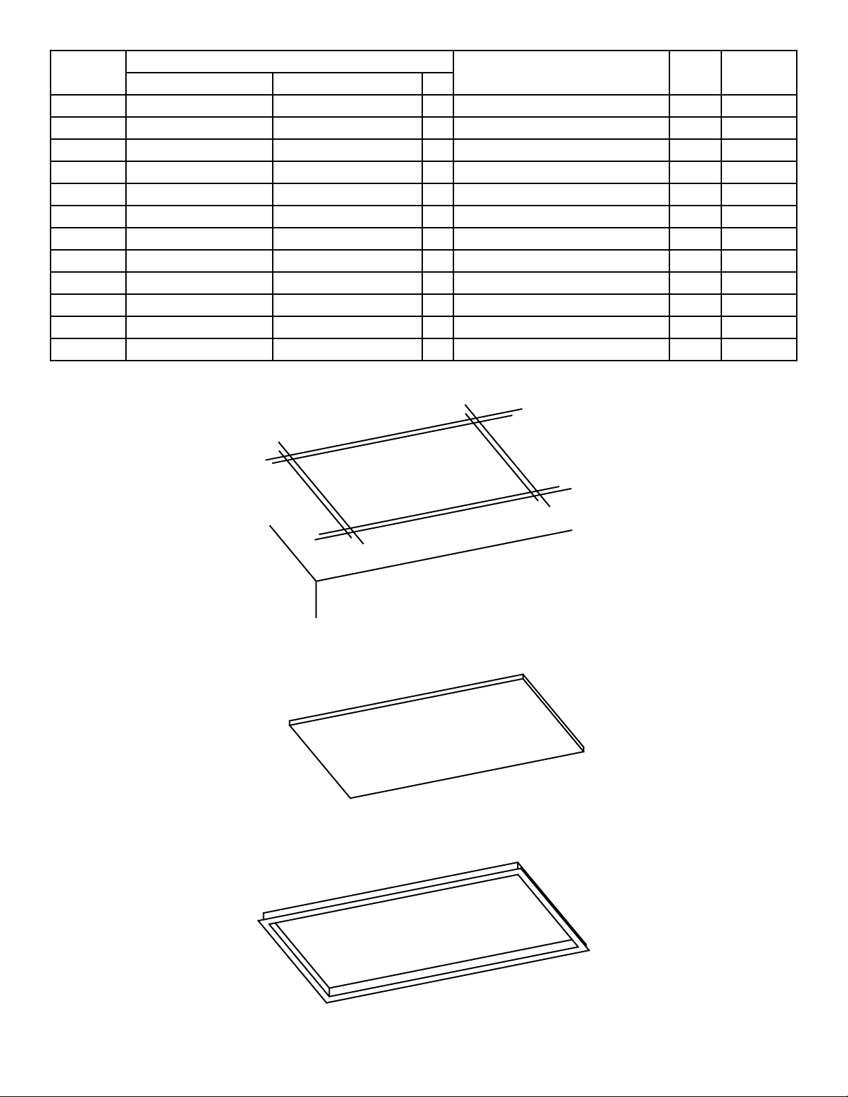
Model
No.
CP805 23 3/4 (603MM) 47 3/4 (1213MM) 1 24 X 48 (610MM X 1219MM) 500 208
CP125 23 3/4 (603MM) 47 3/4 (1213MM) 1 24 X 48 (610MM X 1219MM) 500 120/240
CP705 23 3/4 (603MM) 47 3/4 (1213MM) 1 24 X 48 (610MM X 1219MM) 500 277
CP807 23 3/4 (603MM) 47 3/4 (1213MM) 1 24 X 48 (610MM X 1219MM) 750 208
CP127 23 3/4 (603MM) 47 3/4 (1213MM) 1 24 X 48 (610MM X 1219MM) 750 120/240
CP707 23 3/4 (603MM) 47 3/4 (1213MM) 1 24 X 48 (610MM X 1219MM) 750 277
CP802 23 3/4 (603MM) 23 3/4 (603MM) 1 24 X 24 (610MM X 610MM) 250 208
CP122 23 3/4 (603MM) 23 3/4 (603MM) 1 24 X 24 (610MM X 610MM) 250 120/240
CP702 23 3/4 (603MM) 23 3/4 (603MM) 1 24 X 24 (610MM X 610MM) 250 277
CP803 23 3/4 (603MM) 23 3/4 (603MM) 1 24 X 24 (610MM X 610MM) 375 208
CP123 23 3/4 (603MM) 23 3/4 (603MM) 1 24 X 24 (610MM X 610MM) 375 120/240
CP703 23 3/4 (603MM) 23 3/4 (603MM) 1 24 X 24 (610MM X 610MM) 375 277
A B C
Panel Size
T-Bar Spacing Watts Volts
B
A
RADIANT
PANEL
C= PANEL DEPTH = 1"
B
RECESSED HEATING
PANEL WITH INVERTED
"T" STYLE FRAME
FRAME FOR RECESSED
HEATING PANEL
A
REV 11/15/18 ECO 1-7483 FORM: 9688 2 of 7
Page 3
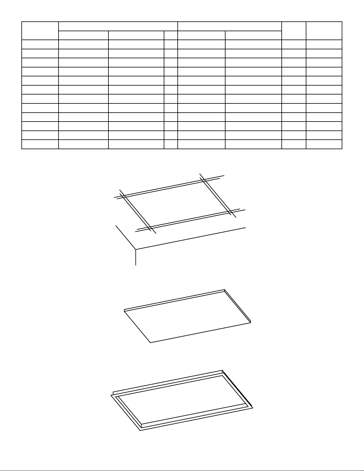
Model
No.
RCP805 21 3/4 (552MM) 47 3/4 (1213MM) 1 22 1/2 (571MM) 48 12 (1232MM) 500 208
RCP125 21 3/4 (552MM) 47 3/4 (1213MM) 1 22 1/2 (571MM) 48 12 (1232MM) 500 120/240
RCP705 21 3/4 (552MM) 47 3/4 (1213MM) 1 22 1/2 (571MM) 48 12 (1232MM) 500 277
RCP807 21 3/4 (552MM) 47 3/4 (1213MM) 1 22 1/2 (571MM) 48 12 (1232MM) 750 208
RCP127 21 3/4 (552MM) 47 3/4 (1213MM) 1 22 1/2 (571MM) 48 12 (1232MM) 750 120/240
RCP707 21 3/4 (552MM) 47 3/4 (1213MM) 1 22 1/2 (571MM) 48 12 (1232MM) 750 277
RCP802 21 3/4 (552MM) 21 3/4 (552MM) 1 22 1/2 (571MM) 22 1/2 (571MM) 250 208
RCP122 21 3/4 (552MM) 21 3/4 (552MM) 1 22 1/2 (571MM) 22 1/2 (571MM) 250 120/240
RCP702 21 3/4 (552MM) 21 3/4 (552MM) 1 22 1/2 (571MM) 22 1/2 (571MM) 250 277
RCP803 21 3/4 (552MM) 21 3/4 (552MM) 1 22 1/2 (571MM) 22 1/2 (571MM) 375 208
RCP123 21 3/4 (552MM) 21 3/4 (552MM) 1 22 1/2 (571MM) 22 1/2 (571MM) 375 120/240
RCP703 21 3/4 (552MM) 21 3/4 (522MM) 1 22 1/2 (571MM) 22 1/2 (571MM) 375 277
A B C D E
Panel Size FRAME OUT SIZE
Watts Volts
B
A
RADIANT
PANEL
C= PANEL DEPTH = 1"
B
RECESSED HEATING
PANEL WITH INVERTED
"T" STYLE FRAME
FRAME FOR RECESSED
HEATING PANEL
A
3 of 7REV 11/15/18 ECO 1-7483 FORM: 9688
Page 4

IMPORTANT INSTRUCTIONS
1. When using electrical appliances, basic precautions should always be followed to reduce the risk of re, electrical
shock, and injury to persons, including the following:
2. Read all instructions before using this heater.
3. CAUTION: High temperature, risk of re, keep electrical cords, drapery, furnishings and other combustibles at
least 3 feet (0.9m) from the front of the heater. Zero clearance on sides and rear.
MISE EN GARDE: Température élevée, risque d’incendie, maintenez les cordons électriques, les draperies,
les meubles et autres matériaux combustibles à au moins 0,9 m de l’avant de l’appareil. Zéro dégagement sur
les côtés et à l’arrière.
4. Extreme caution is necessary when any heater is used by or near children or invalids and whenever the heater is left
operating and unattended.
5. Do not operate any heater after it malfunctions, has been dropped or damaged in any manner. Return heater to
authorized service facility for examination, electrical or mechanical adjustment, or repair.
6. Do not use outdoors.
7. To disconnect heater, turn controls to off, and turn off power to heater circuit at main disconnect panel (or operate
internal disconnect switch if provided).
8. Do not insert or allow foreign objects to enter any ventilation or exhaust opening as this may cause an electric shock or
re, or damage the heater.
9. To prevent a possible re, do not block air intakes or exhaust in any manner.
10. A heater has hot and arcing or sparking parts inside. WARNING: Do not use it in area where gasoline, paint, or
ammable liquids are used or stored.
AVERTISSEMENT: Ne l’utilisez pas dans un endroit où de l’essence, de la peinture ou des liquides inammables sont
utilisés ou stockés.
11. Use this heater only as described in this manual. Any other use not recommended by the manufacturer may cause re,
electric shock, or injury to persons.
12. This heater may include an audible or visual alarm to warn that parts of the heater are getting excessively, hot. If the
alarm sounds (or illuminates), immediately turn the heater off and inspect for any objects on or adjacent to the heater
that may have blocked the airow or otherwise caused high temperatures to have occurred. DO NOT OPERATE THE
HEATER WITH THE ALARM SOUNDING (OR ILLUMINATING).
13. SAVE THESE INSTRUCTIONS
REV 11/15/18 ECO 1-7483 FORM: 9688 4 of 7
Page 5

HEA
TING
SUR
FRAME
RECESSED
ON
PAN
FOR
LY
EATING
H
ELS
PAN
FACE
FRAME
EL
MOUN
WI
TH
T
UNTING
SUR
FRAME
HEA
FOR
CP
TING
FRAME DEPTH = 3"
MO
FACE
"T"
PANE
BA
R
L
RECESSED PANEL FRAME ACCESSORY
FOR USE WITH RECESSED PANELS ONLY
NOMINAL SIZE
22” X 22” (559MM X 559MM)
22” X 48” (550MM X 1219MM)
FACE
SUR
FRAME
SURFACE MOUNTED FRAME ACCESSORY
FOR SURFACE MOUNTED PANELS
CATALOG NUMBERS NOMINAL SIZE
SF200 24” X 24” (610MM X 610MM)
SF400 24” X 48” (610MM X 1219MM)
M
OUN
TING
Frame is constructed of extruded aluminum.
INSTALLATION INSTRUCTIONS
T-BAR CEILING PANELS
All wiring must be in accordance with the latest edition of the N.E.C./C.E.C. and local codes. Install the junction
box above and away from the panel above any ceiling insulation. Reference Fig. 1.
WARNING: Adhere to all applicable building codes and regulations when installing or using ceiling
heaters. Failure to do so could cause improper activation of re suppression systems leading to property
damage or bodily injury.
AVERTISSEMENT: respecter tous les codes et réglementations applicables lors de l’installation ou de
l’utilisation de radiateurs de plafond. L’omission de le faire pourrait entraîner une mauvaise activation
des systèmes de suppression des incendies entraînant des dommages matériels ou corporels.
Use supply conductors suitable for 75OC.
Heater junction box and thermostat outlet box must be grounded through the grounding conductor. Install
heating panels in “T” Bar ceiling maintaining a minimum clearance between overhead ceiling or roof and at back
of panel.for wiring.
CLIP
FIG. 1
JUNCTION BOX
"T" BAR
POWER SOURCE
CLIP
BEND OVER
"T" BAR
THERMOSTAT
HEATING
PANEL
"T" BAR
5 of 7REV 11/15/18 ECO 1-7483 FORM: 9688
Page 6

WIRING INFORMATION
IMPORTANT INFORMATION: READ BEFORE CONNECTING TO POWER SUPPLY
1. Disconnect branch circuit or power supply before connecting or servicing.
2. All wiring must be done in accordance with the N.E.C./C.E.C., or local code having jurisdiction.
3. Do not cover face of heater at any time with an object, other construction or furnishing as over heating could result and
combustion of objects.
4. Check to determine that branch circuit voltage is the same as voltage shown on panel data label. Do not connect to
a circuit having a higher voltage as a hazard can result. Connecting to a lower voltage will result in a lower operating
wattage.
NOTE:
1. The 120 and 240 volt panels are furnished as dual rated 120/240 volt units. The operating volts determines which leads
are to be connected. See Fig. 3
A. For 240 volt connection the two black leads are connected to the eld power supply. The white lead is not used and is
to be insulated by wrapping tape over the open conductor.
B. For 120 volt connection the two black leads are to be spliced together and connected to the black eld power supply
conductor. The white lead is to be connected to the white eld power supply conductor.
C.. Grounding: Connect the eld supply grounding conductor to the panel ground conductor (green).
2. The 208 Volt panels are furnished as single rated units and have two black leads to be connected to the eld supply
power leads in the junction box. Reference Fig. 1 for grounding connection.
3. The 277 volt panels are furnished as single rated units and have one black and one white lead to be connected to the
eld supply power. The black lead must be connected to the black eld power supply lead and the white panel lead
must be connected to the white power supply lead. The single pole thermostat must be connected to the black power
supply lead. Reference Fig. 2 for grounding connection.
208 Volt Model Wiring Connection
Panel Conduit & Leads
B
Field Splice
Remote Junction Box
B
OPERATION
1. Turn on the power supply to heater.
2. Rotate thermostat knob fully clockwise.
3. Allow the room to reach desired temperature, then rotate thermostat
knobcounter clockwise until the heater de-energizes.
Field Conductors
208 Volt
GND
Supply
277 Volt Model Wiring Connection
BW
Field Conductors
DOUBLE POLE
THERMOSTAT
FIG. 1
Panel Conduit & Leads
Field Splice
Remote Junction Box
4. For remote thermostat operation, thermostat wiring must be the same size
as power supply wiring.
120/240 Volt Models Wiring Connection
Panel Conduit & Leads
Field Splice
W
Field Conductors
Remote Junction Box
B W
Panel Conduit & Leads
Tape & Insulate White Wire
Field Splice
Remote Junction Box
Field Conductors
B
B
SINGLE POLE
THERMOSTAT
GND
277 Volt
Supply
SINGLE POLE
THERMOSTAT
FIG. 2 FIG. 3
GND
240 Volt
Supply
DOUBLE POLE
THERMOSTAT
GND
120 Volt
Supply
REV 11/15/18 ECO 1-7483 FORM: 9688 6 of 7
Page 7

RECESSED CEILING PANELS
The recessed ceiling panels are designed to be used with a recessed frame (included with recessed panels)
designed to t the cutout in the ceiling. Ref. Fig. 2. The cutout dimensions are as given in the specication table
for the specic panel model in column D and E. Ref. Fig. 3. The frame must be secured to the framing members
as shown in Fig. 4 using wood screws or nails.
The panel is to be placed through the frame opening and lowered into the frame and wired in accordance with
the N.E.C./C.E.C. and local codes.
WARNING: Adhere to all applicable building codes and requlations when installing or using ceiling
heaters. Failure to do so could cause improper activation of re suppression systems leading to property
damage or bodily injury.
If the junction box is mounted in the ceiling or allowed to be mounted above the upper surface of the ceiling and
below the insulation, 75o C conductors must be used. If the junction box is mounted above the ceiling insulation,
the supply conductors may be rated for 60o C.
"T" BAR
FIG. 2
MOUNTING FRAME
THERMOSTAT
RECESS
JUNCTION BOX
POWER
SOURCE
E
D
FIG. 3
FIG. 4
CEILING JOIST
RADIANT-PANEL
FRAME
Assemble surface mounting frame as shown below using the screws provided. Ref. Fig. 5. Secure the frame
to the ceiling with appropriate hardware. Locate the frame so that the junction box will be covered when the
ceiling panel is installed. Ref. Fig. 6. Remove one end of the frame, insert the ceiling panel and make electrical
connections. Install the end of the frame.
If the junction box is mounted in the ceiling or allowed to be mounted above the upper surface of the ceiling and
below the insulation, 75o C conductors must be used.
If the junction box is mounted above the ceiling insulation, the supply conductors may be rated for 60oC.
JUNCTION
BOX
FIG. 5 FIG. 6
7 of 7REV 11/15/18 ECO 1-7483 FORM: 9688
 Loading...