

Page 1
CEH / 3380 SERIES
CEILING HEATER
Location of Heater:
Heaters are designed for surface, recessed or “T-bar”
ceiling mounting. Heaters must be mounted to provide
a minimum clearance of 8” from the intake or exhaust
end or from the sides of the heater to the nearest wall
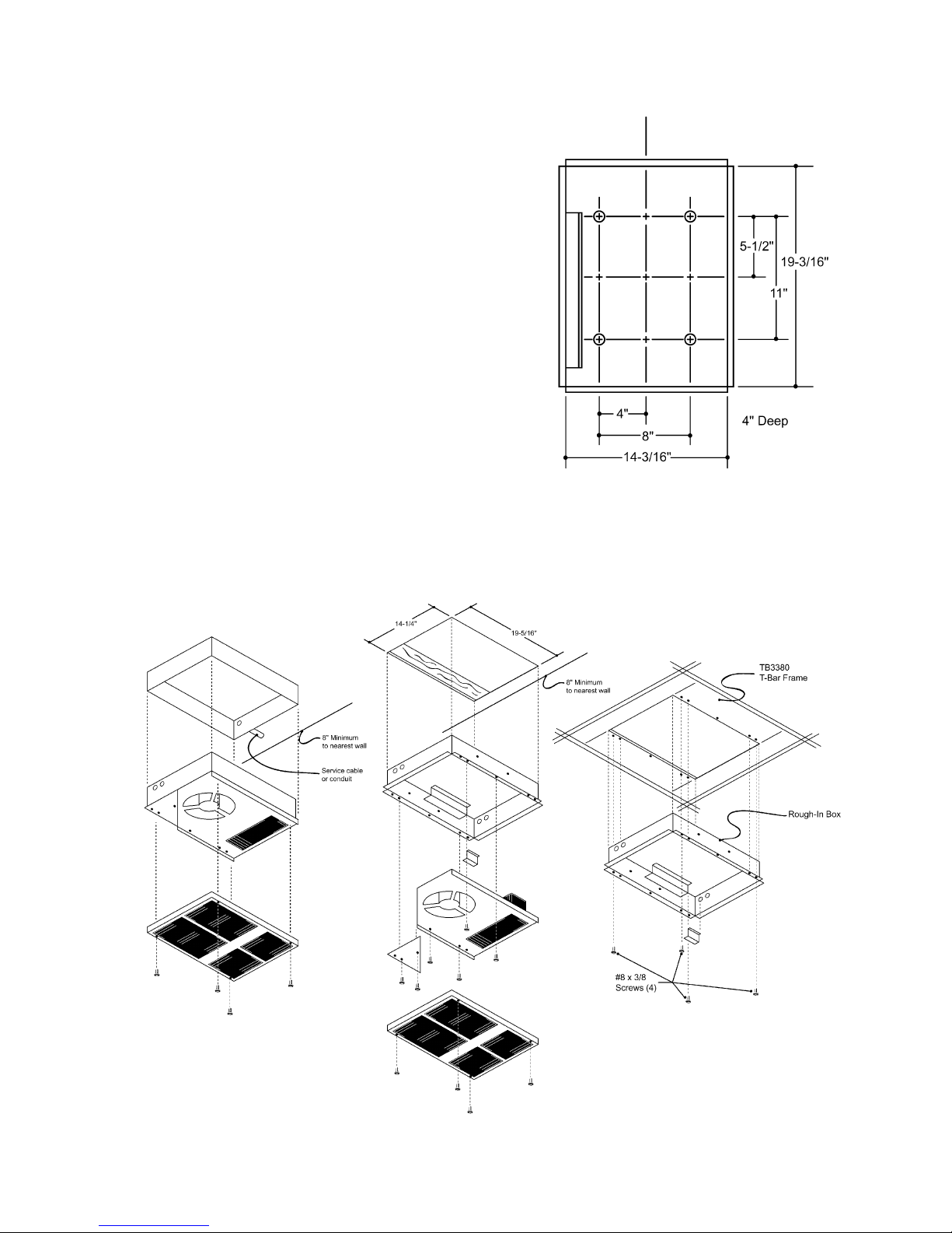
or obstruction. For T -Bar installation (Fig. 3), use the
optional T -Bar frame CEH-TBF / TB3380. Select a 2’ x 2’
section of framework in such a location that the minimum 8” spacing is maintained. Follow the installation
wiring diagram carefully . A green ground lead is provided.
Insure that supply voltage matches voltage rating on the
label of the heater. Disconnect power supply at breaker
box before installation.
Mounting Instructions:
1. Disassemble heater as shown in Fig. 1 & Fig. 2.
2. Flush Mounting (Fig. 2). Provide opening in ceiling
14 1/4” wide by 19 5/16” long. Note that the direction
of air flow is parallel to the 19 5/16” side of the
opening. Depth must be a minimum of 4” from the
finished ceiling surface. Install rough-in box into the
opening so that the flanges are flush with finished
ceiling surface. Secure rough-in box with nails,
screws or appropriate fasteners. Wiring may be
brought into the box from either end using the
knockouts provided.
INSTALLATION
INSTRUCTIONS
B. Run service leads from remote thermostat and
connect to lead wire T1 & T2 with approved
connectors. Replace wiring compartment cover .
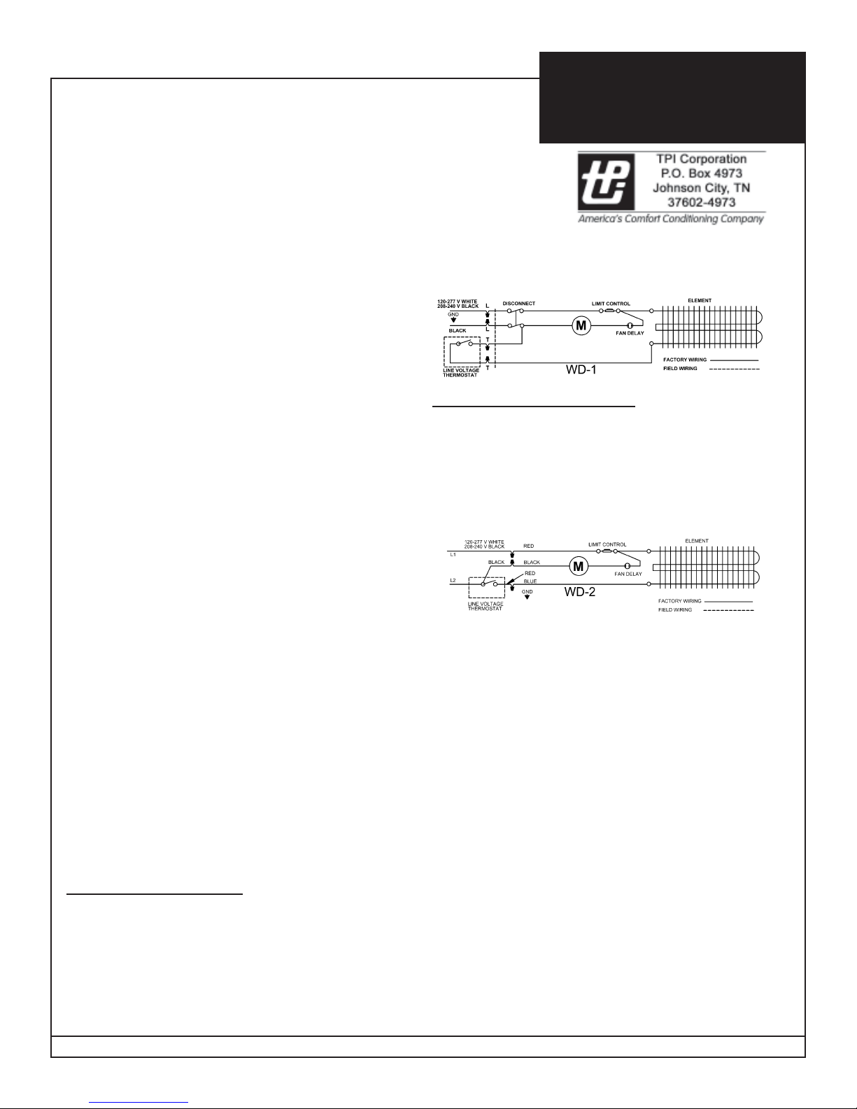
Without Disconnect Ref. WD-2
For proper fan operation, three conductor wires and a
ground wire must be used between the thermostat and
the heater. For 277 and 120 volt applications use a
white, black, red and ground combination. For 208 and
240 volt applications use a black, black, red and ground
combination. The wiring diagram is color coded in this
manner.
3. Surface Mounting (Fig. 1). Insert rough-in box into
surface adapter CEHA /3380EX33. Secure rough-in
box into ceiling through holes provided in the back.
Be sure that rough-in box is centered in the surface
adapter. Bring wiring in through air outlet end knock
outs only.
4. Remove all construction dirt and debris from inside
the heater.
5. Place heater assembly inside the rough-in box and
secure with six screws.
Wiring Instructions:
6. All wiring must conform to National and local
electrical codes.
With Disconnect Ref. WD-1
A. Attach service leads to two black leads (L1 & L2)
on 208-240 volt models and to white (L1) and
black (L2) on 120-277 volt models, with approved
connectors. Connect ground lead to green ground
wire with approved connectors.
For 120 and 200 V olt Operation:
Connect the white (neutral) supply lead to the red pigtail
lead, the black supply lead (L2) to the black pigtail lead,
and the red supply lead (L2) to the blue pigtail lead. The
ground wire should be connected to the green pigtail
lead.
For 208 and 240 V olt Operation:
Connect the black supply lead (L1) to the red pigtail
lead, the black supply (L2) to the black pigtail lead, and
the red supply lead (L2) to the blue pigtail lead. The
ground wire should be connected to the green pigtail
lead. Replace wiring compartment cover.
7. Attach front grille with four screws.
Note: The wall thermostat cycles the heating element
only. Direct runs of supply service leads L1 & L2 supplies
continuous power to the fan motor, and the heater should
be considered live at all times. Move the disconnect
switch to off position or disconnect power at main distribution box before any maintenance work. Turning the
thermostat to off position will not disconnect the heater .
IMPORTANT: OWNER SHOULD RETAIN THESE INSTRUCTIONS FOR FUTURE REFERENCE
Form 9585
Page 2
OPERA TION INSTRUCTIONS:
External Thermostat
The thermostat should be mounted at the level of the
desired comfort zone, but not in the direct path of the
heated discharge air. A single pole thermostat with
anticipator is recommended. Be sure that the ratings
of the thermostat are sufficient to carry the heater
load.
Fan Operation
This heater is equipped with a fan delay control. When
the thermostat calls for heat, the fan control delays the
fan operation until the element is fully hot. Then the fan
will energize and operate. Af ter the thermostat is
satisfied, the element will de-energize and the fan will
continue to run until the element has cooled down. If
the fan does not function in this manner, check all
wiring connections against the wiring diagram.
MAINTENANCE INSTRUCTIONS:
Once a year, disconnect electrical power at source.
Remove front grille and clean dust from heater and
grille. Lubricate the motor with SAE No. 10 oil. T wo oil
spouts are located on front and back of motor . Once
finished turn power back on to heater.
Rough-In Box
Dimensions
Fig. 1
Surface Mounting
Fig. 3
T-Bar Mounting
Fig. 2
Flush Mounting
 Loading...