

Page 1
PAGE 1
9070 Vibration Analysis Copyright © 2012 Test Products International, Inc.
9070 Smart Vibration Meter
Instruction Manual
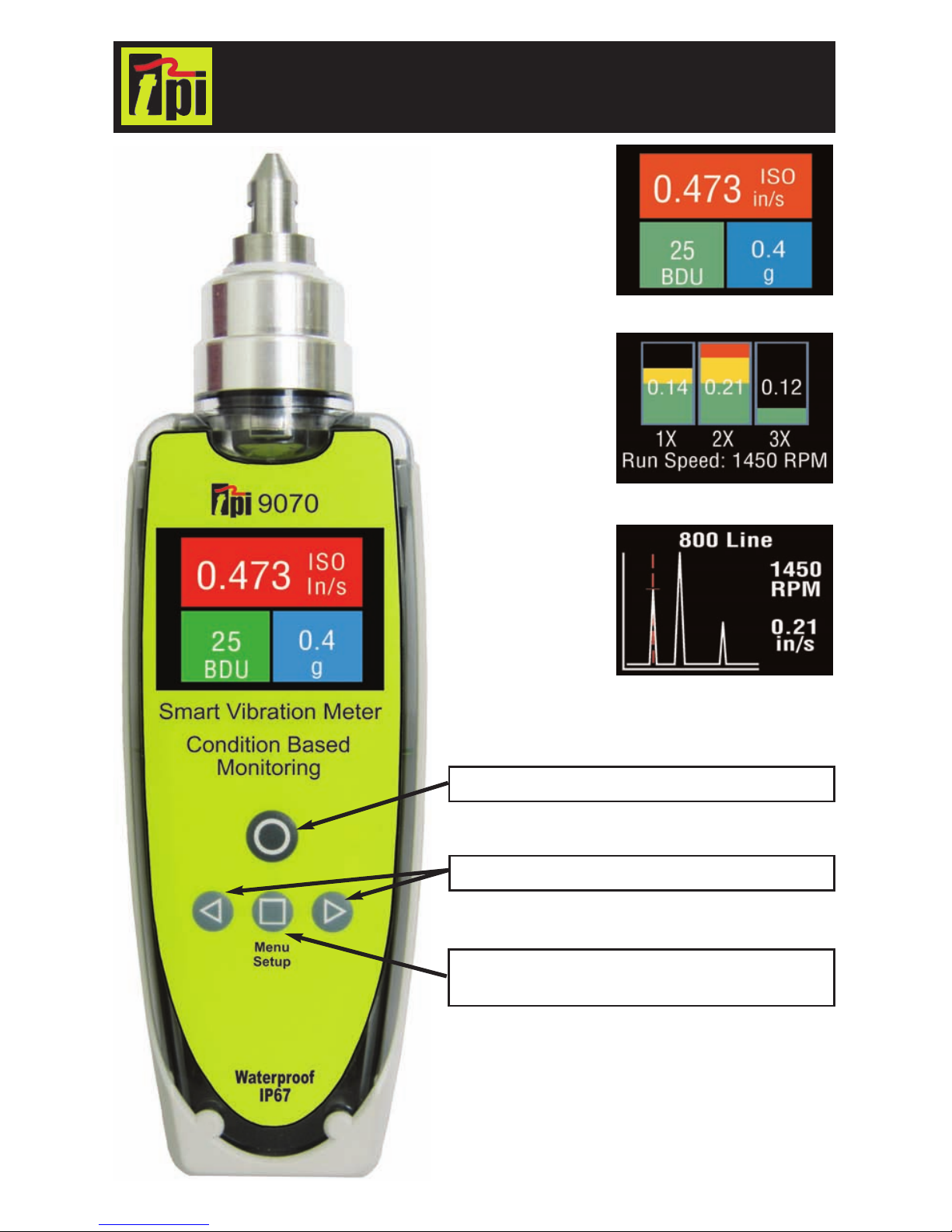
Overall machine and
bearing conditions:
vibration values are displayed
with color coded alarm levels
for ISO values and Bearing
Damage (BDU).
Easy vibration
analysis:
1X (unbalance)
2X (misalignment)
3X (looseness)
Identify complex
issues:
100 to 800-line
spectrum with
zoom and cursor.
Power ON & Measure
Screen Select / Push & Hold for
2 seconds for Menu Setup
Navigation & Cursor Movement
www.GlobalTestSupply.com
Page 2

Copyright © 2012 Test Products International, Inc. 9070 Vibration Analysis
PAGE 2
CONTENTS
DISCLAIMER .................................................... 2
1 OVERVIEW ................................................... 3
1.1 Control buttons................................................ 3
1.2 Batteries .......................................................... 3
1.3 Service ............................................................ 3
2 OPERATION ................................................. 4
2.1 Changing the probe tip.................................... 4
2.2 Taking a reading.............................................. 4
2.2.1 Vibration readings ....................................... 4
2.2.2 Vibration Analysis......................................... 6
2.2.3 Frequency spectrum..................................... 8
2.3 Settings menu ................................................. 9
2.3.1 Setup Wizard................................................ 9
2.3.2 Load & Save Readings ................................ 11
2.3.3 Advanced Settings........................................ 12
2.3.3.1 BDU settings ............................................. 12
2.3.3.2 Units .......................................................... 13
2.3.3.3 Device Settings ......................................... 13
3 SPECIFICATIONS.......................................... 15
4 REVISION HISTORY...................................... 15
5 OPERATION................................................... 16
Disclaimer
This document has been carefully prepared and checked. No responsibility can
be assumed for inaccuracies. TPI reserves the right to make changes without
prior notice to any products herein to improve functionality, reliability or other
design aspects. TPI does not assume any liability out of the use of any product
described herein; neither does it convey any licence under its patent rights nor
the rights of others. TPI products are not authorised for use as components in
life support services or systems. TPI should be informed of any such intended
use to determine suitability of the products.
www.GlobalTestSupply.com
Page 3
PAGE 3
9070 Vibration Analysis Copyright © 2012 Test Products International, Inc.
The 9070 is a simple to use vibration monitoring and analysis tool that
allows easy display of vibration signals. The meter automatically performs vibration analysis functions based on machine running speed to
help diagnose faults such as unbalance, misalignment and looseness.
The system is designed to enable a user to take vibration measurements
from assets (e.g. pumps, motors, fans and bearings). The unit displays
vibration frequency plots and allows vibration severity and bearing
condition to be monitored.
1.1 Control buttons
Turning the meter ON is achieved simply by pressing the power on
(circle) button. The unit automatically turns OFF if not used for 1
minute (this time period can be increased up to 60 minutes using the
Setup Wizard).
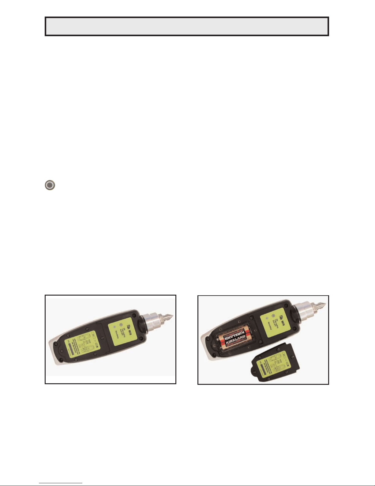
1.2 Batteries
The 9070 requires two AA size batteries and these can be replaced by
removing the battery compartment cover (held in place by 6 screws) as
shown in the photographs below. Use a #1 phillips head screwdriver to
loosen and tighten the battery cover screws. Using the incorrect screwdriver will result in damage to the screws.
Care must be taken when the batteries are changed. Make sure the gasket
is properly seated when reinstalling the battery door otherwise the IP67 rating will be compromised.
1.3 Service
The 9070 contains no user serviceable parts. In the unlikely case of
malfunction, please return the complete unit to your supplier for repair.
1 OVERVIEW
www.GlobalTestSupply.com
Page 4

Copyright © 2012 Test Products International, Inc. 9070 Vibration Analysis
PAGE 4
2.1 Changing the probe tip
Warning: In order to prevent possible damage,
the probe tip should only be tightened using the
machined flats on the probe tip’s mounting plate
and 8mm & 16mm wrenches, as illustrated in the
photo opposite. Do NOT hold or clamp the case of
the Vib Meter when tightening the probe tip or
magnet, as this may cause damage and will invalidate the warranty.
2.2 Taking a reading
To take a reading, briefly press the circle button to turn the unit ON
and then, while holding the tip of the unit against the machine to be
measured, press the circle button again to take the reading.
This causes the overall vibration
numbers screen to be displayed as
shown in the example screenshot on
the left.
This shows an overall view of the
machine’s vibration condition as
explained in the following sections.
2.2.1 Vibration readings
Once a vibration reading has been taken, the display will show three
values, as shown in the screenshot above.
• ISO value (velocity in mm/second or in/sec)
• Bearing Noise in BDU (Bearing Damage Units)
• Total g (acceleration)
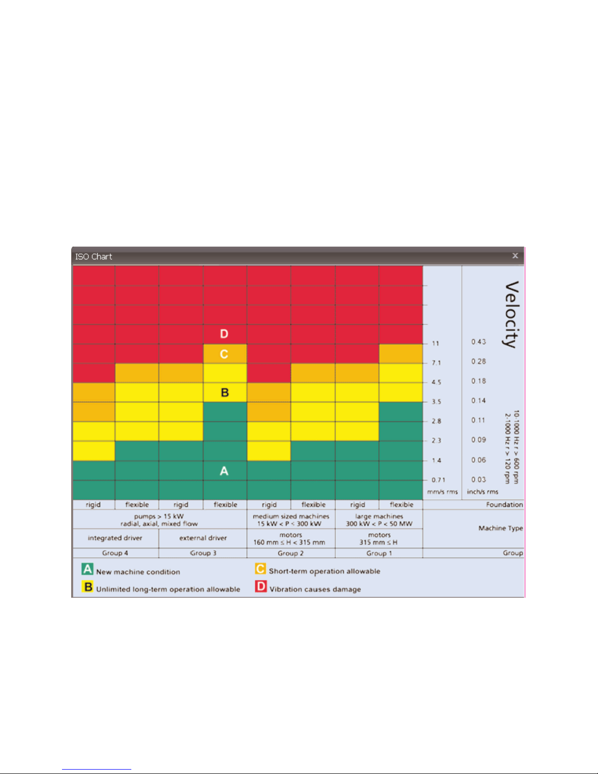
According to ISO standards, values will display on a Green background
indicating a new machine condition, Amber background indicating unlimited long term operation allowable, and Red background indicating vibration causes damage. Total g (acceleration) always displays on a Blue
background. These readings are explained in more detail below with
some examples of what they actually mean:
2 Operation
www.GlobalTestSupply.com
Page 5
PAGE 5
9070 Vibration Analysis Copyright © 2012 Test Products International, Inc.
ISO mm/s or in/sec
The ISO value (in mm/s or inch/s) is the large number at the top of the
screen, which is the RMS value of the vibration velocity in the frequency
band 10Hz (600 RPM) to 1kHz (60,000 RPM), as specified
by the ISO standard
1
.
The ISO value background is color coded according to the ISO 10816-1
vibration velocity level chart (see below). The color coded background
will indicate the condition of the machine according to the relevant
vibration levels for the size and type of machine selected with the
Setup Wizard (see section 2.2.1).
----------------------------------------------------------------------------------------------
1
ISO 10816-1:1995. Mechanical vibration -- Evaluation of machine vibration by measurements on
non-rotating parts
www.GlobalTestSupply.com
Page 6

Copyright © 2012 Test Products International, Inc. 9070 Vibration Analysis
PAGE 6
Bearing Noise (BDU)
Below the displayed ISO value and to the left is the value of bearing
noise (high frequency vibration) in Bearing Damage Units (BDU),
where 100 BDU corresponds to 1g RMS vibration measured above
1kHz. This is a measure of the wear state of the bearings in the equipment being monitored. The higher the number, the more worn the bearing.
It is generally held that 1g of high frequency vibration (100 BDU)
corresponds to a high level of bearing noise and so can be considered
indicative of a damaged bearing. In other words, it may be helpful to
think of the Bearing Noise figure as being very roughly equivalent to
“percentage” of bearing wear.
By default, the bearing noise is displayed on a Red background if it is
above 100 BDU, an Amber background between 50 and 100 BDU
and a Green background below 50 BDU. The BDU alarm levels can be
changed using the Advanced Settings Menu (see section 2.3.3.1).
Total acceleration (g)
This is the RMS (average) value of the total vibration in the ISO
frequency range (10Hz to 1kHz). This reading is shown in units of g
or Earth’s gravitational constant, (where 1g = 9.81 m/s
2
).
2.2.2 Vibration Analysis
Pressing the square button brings
up a display similar to that shown
opposite, which shows the readings
of vibration velocity (mm/s or inch/s)
broken down into each of 3 bands.
The display shows the vibration velocity in frequency ranges that are all
based on multiples of the specified Run Speed of the machine, and as
displayed beneath the 3 bar graphs.
www.GlobalTestSupply.com
Page 7

PAGE 7
9070 Vibration Analysis Copyright © 2012 Test Products International, Inc.
In order to perform a vibration analysis it is important that the running speed of the machine is entered correctly. This is done using
the “Setup Wizard” as described in Section
2.3.1 of this user guide.
The frequency ranges of the bands are based on the following multiples
of running speed
2
:
1X (Unbalance):
The level of vibration in the frequency band based on the running speed
is usually indicative of how well balanced the machine is. A large
vibration at the running speed usually indicates that the machine is out
of balance. However even a very well balanced machine will usually
show some vibration at the running speed but this figure should ideally
be quite low (e.g. typically less than about 2 mm/sec or .11 in/sec for a
medium sized machine).
2X (Misalignment):
Vibration in the frequency band centered at twice the running speed is a
possible indication of misalignment. This is based on the fact that shaft
misalignment can result in a double peak in the waveform due to there
being two different centres of gravity (one from each shaft). In other
words the accelerometer picks up a peak as each centre of gravity
passes by and hence there will be two positive and two negative peaks
each revolution of the shaft. This will typically give rise to a vibration
signal at double the running speed of the machine.
3X (Looseness):
Vibration in the frequency band centered at 3 times running speed is a
possible indication that something may be loose (e.g. loose mounting
bolts, weak foundations etc.) as it is not usual to see third order vibration
in a machine unless there is some structural looseness that is being
“excited” by the vibration of the machine.
----------------------------------------------------------------------------------------------
2
Multiples of running speed are often referred to as “orders”
www.GlobalTestSupply.com
Page 8

Copyright © 2012 Test Products International, Inc. 9070 Vibration Analysis
PAGE 8
2.2.3 Frequency spectrum
Pressing the square button once more brings up a display similar to
that shown below, where the vibration levels are shown as a frequency
spectrum in the range from 0 to 1kHz.
The heights of the peaks indicate the
RMS vibration level in (mm/s or inch/s)
at each frequency point in the spectrum.
The readings to the right of the screen
show the frequency in (Hz or RPM)
and the RMS vibration level in (mm/s
or inch/s) at the position of the cursor
(red dotted line).
The cursor position can be moved by use of the left (<) and right (>)
arrow buttons.
Continuing to press the square button successively increases the
resolution of the frequency axis from 100 Lines (i.e. 10Hz or 600 RPM
resolution) to 200, 400 and finally 800 Lines (i.e. 1.25Hz or 75 RPM
resolution) as shown in the table below.
Increasing the resolution effectively zooms into the frequency spectrum
display and at the higher resolutions the display must be scrolled by
using the left and right arrow buttons in order to view the full spectrum.
Resolution (lines) Resolution (Hz) Resolution (RPM)
100 10 600
200 5 300
400 2.5 150
800 1.25 75
www.GlobalTestSupply.com
Page 9

PAGE 9
9070 Vibration Analysis Copyright © 2012 Test Products International, Inc.
2.3 Settings menu
The Settings menu is entered by pressing and holding down the square
button for 2 seconds.
This brings up the following screen:
Moving up and down the menu is
achieved by pressing the left (up) and
right (down) buttons which causes the
menu item to be highlighted. Pressing
the square button will select the highlighted menu item.
2.3.1 Setup Wizard
Selecting the Setup Wizard opens a dialogue that allows the machine
running speed to be entered and the ISO alarm levels to be set
automatically according to the size and type of machine to be monitored.
The first screen to be displayed shows
the running speed in the previously
selected units (Hz or RPM).
Changing the running speed is
achieved by pressing the left (to
decrease run speed) or right (to
increase run speed) arrow buttons.
www.GlobalTestSupply.com
Page 10

Copyright © 2012 Test Products International, Inc. 9070 Vibration Analysis
PAGE 10
Pressing the square button again
brings up the next screen which allows
the machine type (motor or pump) to
be selected.
Motor - Electrical machine normally
with sleeve or rolling element bearings
and depending on size, operating
speeds above 120RPM to
15,000RPM.
Pump - Multivane impeller with separate or integrated drive (centrifigul,
mixed flow, and/or axial flow) with
sleeve or rolling element bearings.
If a motor is selected the size must
be selected (under or over 300kW) or
if a pump is selected, it must be
specified whether it has an integrated
or external drive unit.
Selecting the machine type and size
allows the ISO alarm levels to be set
accordingly, as does specifying the
type of machine mounting (rigid or
flexible).
As a basic “rule of thumb”, unless a
machine is bolted down to concrete,
it should be considered as being
flexible.
Most motors and pumps are mounted
on some kind of frame or structure
and as such should definitely be
considered as flexibly mounted.
www.GlobalTestSupply.com
Page 11

PAGE 11
9070 Vibration Analysis Copyright © 2012 Test Products International, Inc.
2.3.2 Load & Save Readings
Pressing the square button when Load & Save is highlighted brings up
the following menu:
Selecting Save Reading opens a
screen that allows the user to choose
from one of 3 Memories in which to
save the reading.
Selecting Load Reading brings up a
similar screen from which the user can
choose to load a previously saved
reading from any one of the 3
Memories.
The reading can then be examined in the same way as when it was
first taken via the overall numbers, Vibration Analysis, and frequency
spectrum display screens.
The final option on the Load & Save screen allows the user to select
Demo Data, which loads pre-stored vibration readings from one of two
sets of demonstration data (Demo 1 and Demo 2).
www.GlobalTestSupply.com
Page 12

Copyright © 2012 Test Products International, Inc. 9070 Vibration Analysis
PAGE 12
2.3.3 Advanced Settings
Selecting Advanced from the Settings
menu causes a further menu to
appear as shown in the screen shot
right. Selecting an option is again
done by pressing the arrow buttons
followed by the square button.
2.3.3.1 BDU settings
Selecting BDU Settings allows the alarm levels at which the BDU
readings change color to be altered by the user. Normal levels are
displayed on a Green background.
The BDU threshold values are
designated as Worn Bearing (where
readings turn Amber) and Bad
Bearing (where readings turn Red).
Both these threshold values can be
set independently using the left and
right arrow buttons.
The default BDU thresholds are 50 for
“Worn Bearings” (Amber level) and
100 for “Bad Bearings” (Red level).
These levels are indicative of medium
sized machine bearings operating at
run speeds in the region of 1000 to
3000 RPM.
Higher run speeds may need increased BDU threshold values to identify
worn or bad bearings. Lower run speeds may need decreased BDU
threshold values to identify worn or bad bearings.
www.GlobalTestSupply.com
Page 13

PAGE 13
9070 Vibration Analysis Copyright © 2012 Test Products International, Inc.
2.3.3.2 Units
Selecting Units from the Advanced
Settings menu allows the velocity
readings to be displayed in either
mm/s or in/s (inch/second).
Run Speed units can be displayed in
units of Hertz3 (Hz), RPM or CPM.
2.3.3.3 Device Settings
There are two pages of Device
Settings menus. To advance to the
second page the right arrow button
should be used. Selecting a menu
option is again achieved by pressing
the square button.
The Auto Off Time can be set from 1
minute up to a maximum value of 60
minutes, in increments of 1 minute.
The Brightness level can be set
anywhere between 1 (least brightness)
up to 100 (full brightness).
----------------------------------------------------------------------------------------------
3
Hertz are equivalent to, and also sometimes referred to as, cycles per second (CPS).
4
Revolutions per minute (RPM) are sometimes also referred to as cycles per minute (CPM)
www.GlobalTestSupply.com
Page 14

Copyright © 2012 Test Products International, Inc. 9070 Vibration Analysis
PAGE 14
The operating Language can be
selected from any one of 4 different
languages.
A total of 14 languages are available,
4 of which are loaded depending on
the exact model of 9070.
The Graph Mode can be set to display
the frequency spectrum as either a
Bar graph or a Line graph.
Examples of these two graph modes
are shown below:
3 Maintenance & Care
Wipe clean with soft towel and lukewarm water. Do not place in dishwasher or other cleaning device. Do not use detergents to clean housing. Do not subject meter to water at or above 122
°F (50°C).
Care must be taken when the batteries are changed. Make sure the gasket
is properly seated when reinstalling the battery door otherwise the IP67 rating will be compromised.
Do not drop the instrument. Damage to the probe tip / accelerometer
and/or OLED display may occur.
No internal user serviceable parts.
www.GlobalTestSupply.com
Page 15

PAGE 15
9070 Vibration Analysis Copyright © 2012 Test Products International, Inc.
4 Specifications
5 Revision History
Size
7.9” x 2.4” x 1” (200 mm x 60mm x 26mm)
Weight
9.9oz. (280g) (not including magnet)
Environmental
Water, Sand & Dust:
IP67 Waterproof (Depth of 3.28’ (1m) up to 30 minutes)
Care must be taken when batteries are changed. Make sure gasket
is properly seated otherwise IP67 rating will be compromised.
Never open the meter housing. There are no user serviceable parts
inside. Opening the housing will compromise the IP67 rating.
Operating:
32°F to 122°F (0°C to 50°C)
Storage:
-4°F to 158°F (-20°C to 70°C)
Power supply
2 x AA batteries
Battery life
Auto power OFF - typically 50 hours operating time
depending on brightness setting.
Frequency range
2 Hz to 1 kHz (ISO)
1 kHz to 15 kHz (BDU)
Max frequency resolution
1.25 Hz @ 800 lines FFT setting
Displayed Vibration
Amplitude Units
Acceleration in g
Velocity in mm/s (or inch/s)
Bearing noise in BDU (bearing damage units)
Displayed Frequency Units
Hertz (Hz), RPM or CPM
Input range
+/- 50g
Dynamic range
72 dB (0.05g resolution)
VA diagnostic bands
(RPM = run speed)
Unbalance 1x RPM
Alignment 2x RPM
Looseness 3x RPM
Accessories
• Screw in probe tip (1/4" UNF 28) part number A9071
• Nylon carrying case part number A9070
Options
• Accelerometer mounting magnet part number A9073
• Extended probe tip (stinger) part number A9072
ISSUE PAGES DATE NOTES
1.0 16 March 2012 First Issue - JKA
www.GlobalTestSupply.com
Page 16

Copyright © 2012 Test Products International, Inc. 9070 Vibration Analysis
PAGE 16
Test Products International, Inc.
Headquarters:
9615 SW Allen Blvd.
Beaverton, OR 97005 USA
503-520-9197
Fax: 503-520-1225
info@tpi-thevalueleader.com
Test Products International, Ltd.
Canada
905-693-8558
Tall Free: 866-693-8558
Fax: 905-693-0888
info@tpicanada.com
Test Products International UK Ltd.
Tel: +44 (0)1293 561212
Fax: +44 (0)1293 813465
e-mail: info@tpi-uk.com
Standard accessories
Optional accessories
Company Info
Photo Actual Size
A9070: Carrying case
A9071: Standard stinger
A9073: Magnet
www.GlobalTestSupply.com
 Loading...