

Page 1
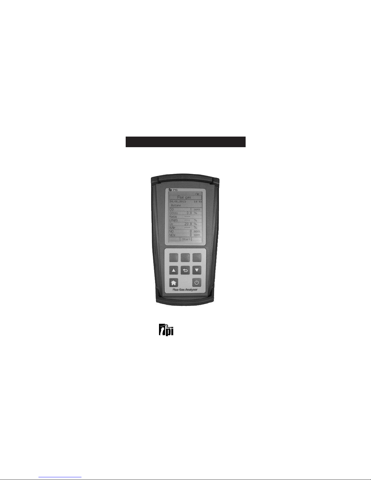
TPI 716
Flue Gas Analyser
The Value Leader
TM
www.GlobalTestSupply.com
Find Quality Products Online at: sales@GlobalTestSupply.com
Page 2

Contents
Introduction........................................................1
General Overview.................................................1, 2
Instrument Overview............................................. 3 ~ 7
Front View...............................................3
Keypad...................................................4
Back View...............................................5
Side Views..............................................6
Top View................................................ 7
Basic Analyser Functions....................................... 8 ~ 10
Charging The Analyser................................8
Turning The Analyzer On ............................ 9 & 10
Measurements.................................................... 11 ~ 24
Flue Gas................................................ 11 ~ 17
Temperature & Pressure.............................18 ~ 20
CO Room Test..........................................21
Tightness Test......................................... 22 & 23
Combustible Gas Leak Detection...................24
Menu Navigation................................................. 25 ~ 28
Memory................................................ 25
Fuel Type................................................26
Analyzer Setup.........................................27
Units of Measure, Instrument Info................. 28
Turning The Analyzer Off........................................29
Specifications..................................................... 30 & 31
Calibration & Service............................................ 32
Warranty........................................................... 32
Appendix A General Maintenance & Function Tests............32 ~ 35
Appendix B Error Codes and Troubleshooting....................36 & 37
www.GlobalTestSupply.com
Find Quality Products Online at: sales@GlobalTestSupply.com
Page 3

Introduction
Thank you for purchasing TPI brand products. The TPI 716 Flue Gas
Analyser is a state of the art, easy to use analyser designed not only to
display and calculate the required readings from a flue but also to cover
most of the other measurements associated with combustion. The
instrument is ruggedly constructed and comes with a 6 Year Guarantee
subject to annual servicing being carried out by TPI or one of their
approved service centres.
General Overview
The following guidelines will help prevent damage to your sensors:
Always use the mini pump filter when testing flue gases.
Periodically check and replace the mini pump filter as needed.
Always make sure the in-line filter / water trap is installed properly.
Periodically check and replace the in-line filter as needed.
Always remove water or condensation from the inside of the in-line
filter / water trap assembly prior to performing tests.
Always use the optional oil filter (p/n A773) when performing tests on oil
burning equipment unless you are using the 716 with an NO
sensor fitted. Do not use the A773 on the 716 with NO sensor fitted
because the A773 will filter out Nitric Oxide (NO).
Never over saturate your sensors by performing tests on equipment with
gas levels beyond the capability of you analyser.
Always keep the A796 water trap / filter assembly clean & dry and replace
the internal filter as necessary. (Replacement filter part number is A796-F.)
1
www.GlobalTestSupply.com
Find Quality Products Online at: sales@GlobalTestSupply.com
Page 4

General Overview (Continued)
This manual will guide you through the functions of the TPI 716 which will
give you many years of reliable service.
Your TPI 716 Flue Gas Analyser comes complete with the following
standard accessories:
( ) Denotes part number
• TPI 716 Analyser
• Rubber Boot (A765) 1 each installed on analyser
• Soft Carrying Case (A768) - 1 each
• Flue Sampling Probe (A770) - 1 each
• In-Line Filter / Water Trap installed on Flue probe (A796) - 1 each
• Disc water filter installed in water trap (A796W) - 1 each
• Spare In-Line Filter - 1 each (A796F is a package of 10 filters)
• Temperature Probe (GK11M) - 1 each
• Battery Charger (A766) - 1 each
• Mini Pump Protection Filter Assembly (A763) - 1 each
• Exhaust Spigot Removable (A764) - 1 each
• Pressure Adaptors - Pair (A772) - 1 pair
• PC Software and cable for communication to a PC (A807).
• Instruction Manual
Your TPI 716 Flue Gas Analyzer has the following options/upgrades
available:
• Plug-In Combustible Gas Sniffer Leak Probe (716-Leak)
• Upgrade to Bluetooth connectivity (716-BT)
• Upgrade to NO sensor for Calculated NOx (716-NO)
• Upgrade to High CO Sensor-up to 10% range (716-HCO)
• Infra Red Printer (A740)
• Temperature Pipe Clamps - pair (CK21M/Pair)
• CPA1 Probe Kit (CPK3)
• Smoke Pump (A788)
• Oil (Sulfur) Filter (A773)
2
www.GlobalTestSupply.com
Find Quality Products Online at: sales@GlobalTestSupply.com
Page 5

Instrument Overview
Front View
Rubber Boot Protects the instrument from accidental damage
Display Large graphical backlit LCD Display
Keypad Selects all available functions
Rubber
Boot
LCD
Display
Keypad
3
www.GlobalTestSupply.com
Find Quality Products Online at: sales@GlobalTestSupply.com
Page 6
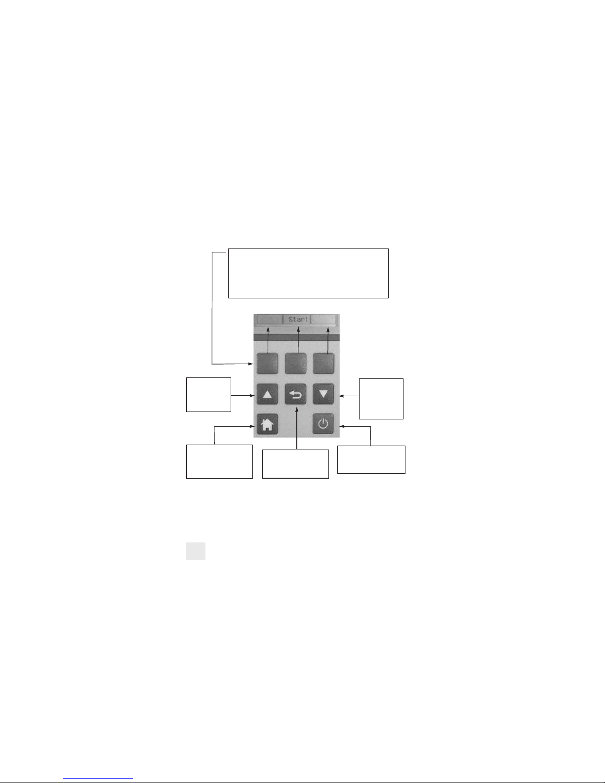
Keypad
4
Blue Soft Keys - The function of these keys is shown in the
lower part of the display and changes depending on what
menu the analyser is in.
In the picture center soft key controls the start function and
the left and right soft keys are disabled.
Up Arrow Key This key is used
to scroll up in
menus.
Down Arrow
Key - This key
is used to scroll
down in menus.
Home Key - This key is
used to return to the
Main Menu from any
other menu.
Back Key - This key is
used to go back one
menu level.
On/Off Key - This key is
used to turn the analyser
on and off.
www.GlobalTestSupply.com
Find Quality Products Online at: sales@GlobalTestSupply.com
Page 7

Back View
Calibration and Information Label: Displays calibration information and
serial number
Battery Compartment: Holds rechargeable battery
Rubber Boot Protects the instrument
5
Rubber
Boot
Information
Label
Thermocouple
Sockets
Infrared
Window
Battery
Compartment
Exhaust
Port
Calibration
Information
Gas, Pressure, USB &
Leak Probe Ports
www.GlobalTestSupply.com
Find Quality Products Online at: sales@GlobalTestSupply.com
Page 8

Side Views
Exhaust Port Port for connection of Exhaust Adapter
Infrared Window Window for sending stored data to IR Printer
Rubber Boot Protects the instrument from accidental damage
6
Rubber Boot
Exhaust Port
Infrared Window
Rubber Boot
Left Hand
Side
Right
Hand Side
www.GlobalTestSupply.com
Find Quality Products Online at: sales@GlobalTestSupply.com
Page 9

Charger Socket Connection for 220V/115V charger
T1 Socket Connection for thermocouple plug on flue probe
Connection for any 'K' type thermocouple probe
T2 Socket Connection for ambient 'K' type thermocouple probe
Connection for any 'K' type thermocouple probe
Gas Sample Port Connection for Mini Pump Protection Filter and Flue Probe
P (+) Port Connections for Pressure Tubing
P (-) Port
USB Port Connection for A807 cable for communication
to a PC or connection for 716-Leak combustible gas leak
detection sniffer probe.
Top View
7
Charger
Socket
USB Port
P(+)
Port
P(-)
Port
Gas
Sample
Port
T1 Socket
T2 Socket
www.GlobalTestSupply.com
Find Quality Products Online at: sales@GlobalTestSupply.com
Page 10
BASIC ANALYSER FUNCTIONS
Charging The Analyser
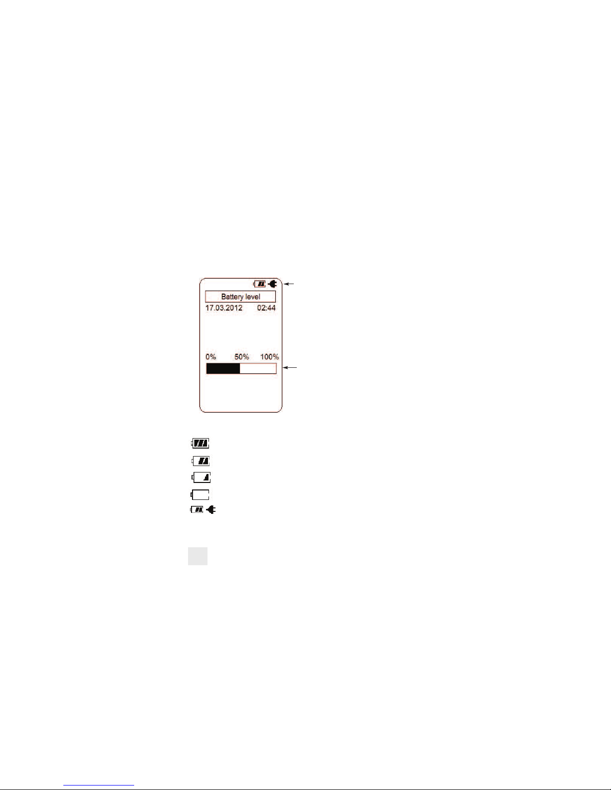
Plug the charger into the charger socket on the instrument (see page 7). When the
charger is plugged in the battery level display will turn on. This display indicates
the analyser is being charged and the status of the charge.
The plug symbol confirms the
analyser is connected to the charger.
The battery symbol shows the charge
level when the analyser is on too.
The charge level is represented in
graph form as well. The charge is
displayed in percentage. (0 to 100%)
During operation the analyser will display charge status and battery condition in
the top right corner of the display.
Battery is at full capacity.
Battery is at 2/3 capacity.
Battery is at 1/3 capacity. The charger should be connected soon.
Battery is very low and needs to be recharged immediately
Indicates the analyzer is connected to the charger.
If a beeping noise is heard during charging disconnect the charger. This is an
indication the battery pack needs to be replaced.
8
www.GlobalTestSupply.com
Find Quality Products Online at: sales@GlobalTestSupply.com
Page 11
Turning The Analyser On
Always: - Before turning on please ensure that ONLY the in-line pump protection
filter is connected to the Gas Sample Port. This in-line pump protection filter
MUST be fitted to the instrument at all times!!
Please DO NOT
have the gas sampling probe attached at this point. The gas
sampling probe needs be fitted to the 716 only at the point where combustion
analysis begins. See page 14
Press and hold the ON/OFF key down for approximately 3 seconds. The 716 will
beep and the initial start up screen will be displayed.
After approximately 5 seconds the Main menu will be displayed & the 716 is ready
to use. However, as the Next Calibration Due Date Approaches or is Overdue one
of the following screens may appear:-
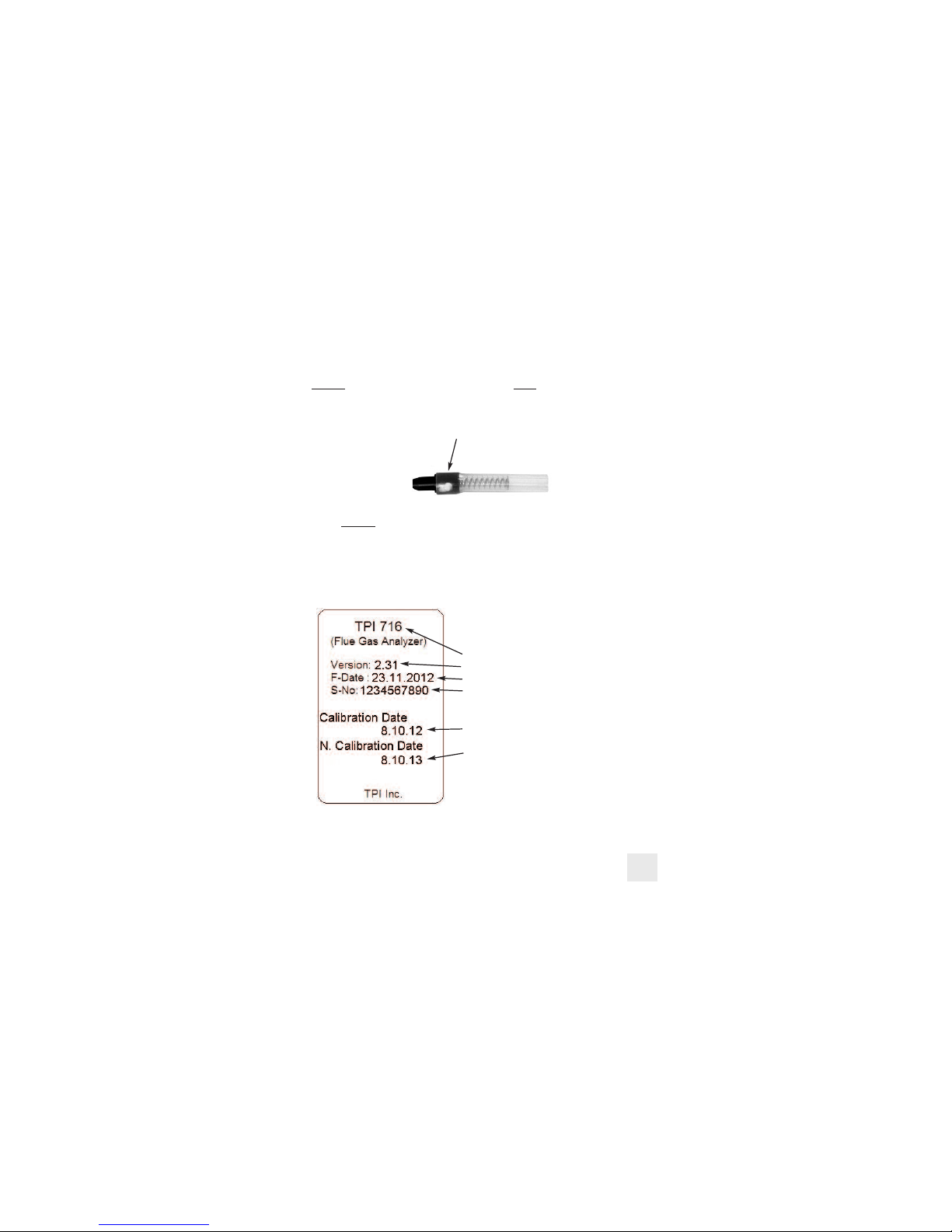
The initial start up screen displays the
following information:
Model number of the analyser
Firmware version
Firmware date
Serial number of the analyzer
Date Last Calibration was carried out
Date Next Calibration is due
9
Pump Protection Filter
www.GlobalTestSupply.com
Find Quality Products Online at: sales@GlobalTestSupply.com
Page 12
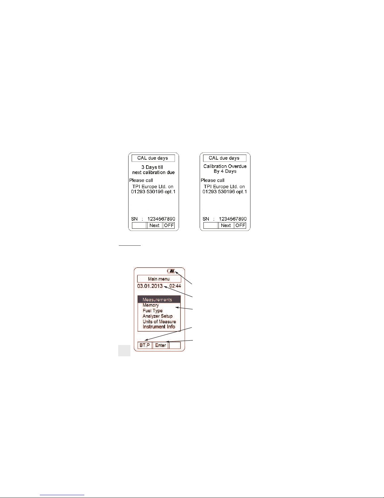
Turning The Analyser On (continued)
The main menu displays the following
information:
Battery status
Date (dd.mm.yyyy format) and time
(24hr clock)
Menu Selections
Left blue soft key activates Bluetooth
(Only models equipped with this option.)
Center blue soft key confirms selection
10
Choosing “Next” will move you onto the Main Menu Screen as displayed below.
Please Note: It is a requirement of BS7967 that an FGA is within calibration and used
in conjunction with the manufacturers instructions therefore it is NOT recommended
that “Next” be chosen by the user if the “Calibration Overdue” Screen appears. Doing
so will contravene the requirements of BS7967.
www.GlobalTestSupply.com
Find Quality Products Online at: sales@GlobalTestSupply.com
Page 13

MEASUREMENTS - Flue Gas
Note: It is recommended you perform routine general maintenance on your
analyser to ensure proper function. Please refer to Appendix A for further details
The pump will start and the Zeroing screen will
display. The analyser is initializing and self
testing the sensors during this 30 second cycle.
The selected fuel type will be displayed and can be
changed as necessary (see pg 12).
The selected unit of efficiency is displayed
and can be changed as necessary (see pg 13).
If the analyser is ready for use, “Skip” will
appear above the center soft key. Pressing this
will bypass the 30 second countdown.
Turn the 716 on as outlined on page 9. After
the initial start up screen the Main Menu will
be displayed.
Using the Arrow keys select Measurements by
highlighting it.
Press the Enter key (centre soft blue key) to
confirm the selection.
The Measurements menu will be displayed.
Using the Arrow keys select Flue gas by high
lighting it.
Make sure the analyser is in a clean air environment
with only the in-line pump protection filter
connected to the input.
Press the Enter key (centre soft blue key) to confirm
the selection.
11
www.GlobalTestSupply.com
Find Quality Products Online at: sales@GlobalTestSupply.com
Page 14

MEASUREMENTS - Flue Gas (continued)
As necessary, the fuel type can be changed to match
the fuel type of the equipment under test. The fuel
type is used in the CO2, Ratio & efficiency calculations
and therefore it is important the fuel type is correct in
order for the calculation to be accurate.
To change the fuel type use the Arrow keys to
highlight “Fuel change”.
Press the Chang key (left soft blue key) and the fuel
menu will display.
The Arrow keys are used to scroll through the
available fuel types.
The available fuels are Natural gas, Light oil, Heavy
oil, LPG, Bituminous coal, Anthracite coal, Coke,
Butane, Wood (dry), and Bagasse.
Once the desired fuel type is highlighted press the
center soft key (OK) to confirm the selection.
The analyser will return to the Zeroing display and the
countdown will continue.
12
NOTE: When selecting oil as fuel be sure to use the optional
oil filter (A773) or readings could become erratic. See
Appendix E for installation instructions.
Do NOT
use the A773 with a 716 analyser with the NO
Sensor Upgrade.
www.GlobalTestSupply.com
Find Quality Products Online at: sales@GlobalTestSupply.com
Page 15

After the initial purge cycle is complete or skip is
pressed the Flue gas measurement screen will
display.
This screen displays all combustion parameters
including NO & NOx (if fitted), temperature, pressure,
excess Air and Pump Speed.
If an NO sensor is fitted then the Right Hand Down
Arrow Key needs to be pressed to see Pressure &
Pump Speed as well as Temperature.
MEASUREMENTS - Flue Gas (continued)
The unit of efficiency can be changed as needed
between Nett, Gross & Condensing. Nett efficiency
doesn’t take into account wet losses while Gross
efficiency does. Condensing efficiency is a common
calculation applied is some European Countries.
Press the right soft key (Next) to highlight “Efficiency
change” in the display.
Press the Chang key (left soft key) and the efficiency
menu will display.
Use the Arrow keys to select the desired efficiency
unit and press the center soft key (OK) to confirm the
selection.
If only CO & O2 sensors are fitted then the bottom 2
spaces on the initial front Flue Gas Measurements
Screen will display Pressure & Pump Speed. Pressing
the Right Hand Down Arrow Key will scroll through
and display the other parameters such as
Temperature etc...
13
www.GlobalTestSupply.com
Find Quality Products Online at: sales@GlobalTestSupply.com
Page 16

MEASUREMENTS - Flue Gas (continued)
Connect the Gas Sampling Flue Probe Tubing complete to the In-Line Pump Protection
Filter (see below) and the 'K' Type Thermocouple Plug from the Flue Probe into
Thermocouple (T1) Socket. The GK11M ambient air temperature probe is connected to
the (T2) socket.
WARNING: - Ensure the 'K' type thermocouple probes are inserted into the sockets
correctly (see page 7). The plugs are polarity marked and forcing the plug into the
socket the wrong way may result in damage to the instrument.
In-line Filter
Assembly
Ambient Air
Connection (T2)
Flue Probe
Tubing
GK11M Probe
Thermocouple
Connection from
Flue Probe
Pump Protection Filter
Press the center Blue Soft Key (Start) and the pump
will start. The following screen will display:-
Press the Left Blue Soft Key to send the Displayed
Readings Directly to the Optional A740 IR Printer
Press the Right Blue Soft Key to Hold the desired
readings on the screen giving you the option to Save
or Send them to Memory, IR Printer or PC.
Press the Centre Blue Soft Key to Stop the Pump
Running. The Pump will only stop running if the CO
level is below 10ppm otherwise this option is disabled.
14
www.GlobalTestSupply.com
Find Quality Products Online at: sales@GlobalTestSupply.com
Page 17

MEASUREMENTS - Flue Gas (continued)
Insert the flue probe into the sample hole of the device under test. The probe tip
should be in the middle of the flue pipe or exhaust stream.
Ensure the In-Line Filter / Water Trap hangs below the analyser in the proper vertical
position when readings are being taken. Failure to comply reduces the effectiveness of
the water trap and may result in damage to the instrument. Refer to the pictures below
for correct and incorrect use.
WARNING: - Should the CO reading rise above 2,000ppm a continuous series of Alarm
Beeps will be heard. The Probe should immediately be disconnected from the
instrument and the instrument returned to a clean air environment. This Alarm alerts
the user that there is a high concentration of CO, and this procedure will protect the
sensors within the instrument. The alarm level can be changed. Please see Appendix D
Make sure to check the water trap periodically during testing to ensure it does not fill
with condensate and empty it as necessary. If the filter begins to fill during a test, open
the lid and empty out the condensate. After closing the lid, allow readings to stabilize
again.
IMPORTANT: The water trap is fitted with a water block filter (p/n A796-D) in the lid to
prevent water from flowing down into the pump. If the water trap fills the water block
filter will stop the flow to the analyzer and FLO ERR will display. The water trap should
be emptied immediately if this happens. The water block filter may need to be dried out
or replaced before testing can resume.
15
www.GlobalTestSupply.com
Find Quality Products Online at: sales@GlobalTestSupply.com
Page 18

MEASUREMENTS - Flue Gas (continued)
Allow the readings to stabilise. Multiple parameters can be seen in the display.
16
• Carbon Monoxide (CO) reading in parts per million
(ppm)
• Carbon Dioxide (CO2) figure in percentage (%)
(calculated)
• CO/CO2 (Ratio) figure.
• Calculated Efficiency (Eff.) figure in percentage
• Oxygen (O2) reading in percentage (%)
• Excess Air (X Air) in percentage
• Nitric Oxide (NO) (measured) and Nitrogen Oxide
(NOx) (calculated). If Fitted.
• Carbon Monoxide (CO) reading in parts per million
(ppm)
• Carbon Monoxide Air Free (COAF) in parts per million
(ppm) (calculated).
• Nitric Oxide (NO) (measured). If Fitted
• Temperature T1-ST (stack temperature)
• T2-AT (ambient temperature).
• Temperature T1 - T2 (DT)
• Pressure (Prsu)
• Pump speed in cc/min.
Pressing the Up / Down Arrow keys enables the rest of the screen to be displayed.
Once the combustion readings have stabilised they can be “Printed” directly to the
optional IR (A740) Printer by lining up the IR window on the side of the FGA (see page
6) & the IR window on the Printer. Alternatively the stabilised readings can be “HELD”
on the screen. Once the readings are held on the screen the following options are
available:- “Send” the held readings to the A740 Printer or to a Compatible PC or
“Save” the readings to a memory location of your choice. These options are explained
in further details on page 17.
www.GlobalTestSupply.com
Find Quality Products Online at: sales@GlobalTestSupply.com
Page 19

MEASUREMENTS - Flue Gas (continued)
The “Held” data can be saved to a memory location
by pressing the Save key (right blue soft key) and
“Real Data Save” and “Address:” will be displayed.
Using the Up and Down Arrow keys select the
memory location to save the data.
Press the OK key (center blue soft key) to save the
data to the 716 internal memory.
Press the “Back” key at anytime to go back to
“Held” Readings
The “Held” data can also be sent to an optional
infrared printer (p/n A740) or to a PC using optional
cable and software by pressing the Send key (left
blue soft key) and “Print Out” and “PC Out” will be
displayed.
Using the Up and Down arrow keys select the type of
output you require. If sending data to a PC, connect
the USB cable to the analyzer and computer and run
the 716 PC software.
Press the OK key (center blue soft key) to print or
send data to a PC.
Press the “Back” key at anytime to go back
to “Held” Readings
Choosing the “HOLD” option will display the following screen:-
Please note the 3 new options on the Soft Blue Keys
The TPI 716 will continue to monitor live readings in
the background whilst the “Held” readings are on the
display until the “unHold” option is chosen.
You can “Save”, “Print” or “Send” out as many sets
of these readings as you require whilst the 716 is in
“Hold” mode.
Once the “unHold” button is pressed then the 716 will
return to Live readings as explained on Page 16.
17
www.GlobalTestSupply.com
Find Quality Products Online at: sales@GlobalTestSupply.com
Page 20

Measurements - Temperature & Pressure
18
From the Main menu screen using the Up / Down
Arrow keys select “Measurements” in the menu.
Press “Enter” (center blue soft key) to confirm the
selection.
From the Measurements menu use the Up / Down
Arrow keys to select “Temp/Pressure” in the menu.
Press “Enter” (center soft blue key) to confirm the
selection.
The Temperature / Pressure screen will display.
This screen displays both T1 and T2 channels of
temperature as well as the difference between T1 and
T2 (DT).
If no probe is connected to the input “-----” will be
displayed indicating an open connection.
Pressure (Prsu) is also displayed in this screen.
www.GlobalTestSupply.com
Find Quality Products Online at: sales@GlobalTestSupply.com
Page 21

Measurements - Temperature & Pressure (continued)
Measuring Temperature -
1. Ensure you have a 'K' type probe connected to one or both of the thermocouple
sockets T1 / T2 (refer to figure below)
WARNING: - There is ONLY one correct way to connect the 'K' type thermocouple
plug into the socket (see page 7). Forcing the plug into the socket the wrong way
may result in damage to the instrument.
2. Touch the temperature probe to the item under test and read the displayed
temperatures on the LCD.
Other Features:
• Pressing “Send” (center blue soft key) activates a
sub-menu and allows information to be sent to the
optional A740 infrared printer or to a PC using the
optional USB interface cable and software.
• Pressing “Save” (right blue soft key) activates a
sub-menu that allows the screen data to be saved in
a memory location (0 to 99) for later retrieval.
• Pressing “Zero” (left blue soft key) zeros the
manometer. This is used prior to measuring pressure.
NOTE: Analyser shown in picture above with optional second
GK11M probe. Analyser ships with one GK11M as standard.
19
www.GlobalTestSupply.com
Find Quality Products Online at: sales@GlobalTestSupply.com
Page 22

Measurements - Temperature & Pressure (continued)
Measuring Pressure -
1. Ensure you have Pressure Sampling Tube connected to one or both of the
Pressure Ports and there are no restrictions in the tubing (see figure below). The
716 is supplied with a pair of pressure adaptors to allow 1/4” bore hose to be
attached to the pressure ports.
2. Zero the display by pressing the “Zero” Key (left blue soft key).
3. Connect the tube(s) to the device under test and read the pressure on the
display.
The 716 incorporates a differential manometer. Pressure applied to the (-) port is
subtracted from the pressure applied to the (+) port.
20
Other Features:
• Pressing “Send” (center blue soft key) activates a
sub-menu and allows information to be sent to the
optional A740 infrared printer or to a PC using the
optional USB interface cable and software.
• Pressing “Save” (right blue soft key) activates a
sub-menu that allows the screen data to be saved in a
memory location (0 to 99) for later retrieval.
• Pressing “Zero” (left blue soft key) zeros the
manometer. This is used prior to measuring pressure.
www.GlobalTestSupply.com
Find Quality Products Online at: sales@GlobalTestSupply.com
Page 23

Measurements - CO Room Test
The CO room test function enables the 716 to monitor and log ambient CO levels in a
room or office space at 1 minute intervals. This data can be retrieved later via the
optional infrared printer or serial cable and software.
1. Begin with the 716 in a fresh air environment
outside of the test area. From the main menu select
“Measurement” as outlined on pages 10 & 11. From
the “Measurements” menu select “CO room test” and
the zeroing screen will display.
2. If “Skip” is displayed the analyser sensor is zeroed
and ready for use. Press the center blue soft key to
move to the next screen. If “Skip” is not displayed,
wait for the zero process to finish and the next screen
will be displayed automatically.
3. After the zero process the CO room test display will
appear. At this time the page address where the data
will be stored can be changed as necessary. Press the
“Chang” key (left blue soft key) and use the Arrow
keys to change the address location.
4. Press the “Start” key (center blue soft key) to begin
CO monitoring. The pump will start and the 716 will
begin storing readings every minute. The number of
readings stored can be seen at the bottom of the
screen. The real, minimum, maximum, and average
CO measured will be displayed too.
5. When the 30 minute test period is up (or the
desired number of readings have been taken and the
test stopped by pressing “Stop” - centre blue soft
key) the 716 will move to the next screen and give
you the options in point 6.
6. Stored readings can be sent to a PC or printer by
pressing the “Send” key (left blue soft key) and
selecting “Print Out” or “PC Out”.
21
www.GlobalTestSupply.com
Find Quality Products Online at: sales@GlobalTestSupply.com
Page 24

This function is designed to step you through each
stage of the Let-By/Timed Tightness Test allowing you
to Pass/Fail at the end of each stage and record the
results either to memory for future use or directly to
the optional IR (A740) printer.
1. From the main menu select “Measurement” as
outlined on page 10. From the “Measurements” menu
select “Tightness test” and the standby screen will be
displayed.
2. Press the center blue soft key to “Enter” and begin
the Let-By/Stablisation/Tightness Test.
3. On the first Let-By screen you can Zero the
pressure before connecting up any pressure tubes and
beginning the series of tests.
4. The memory location (0 - 99) can also be changed
at this point before the test commences by pressing
the right blue soft key to highlight the address location
number. Use the Up/Down arrow keys to select the
required numbered location then the centre blue soft
key “OK” to confirm the change.
5. Once you have selected the desired memory
address location and the pressure has been zeroed
you can begin the test procedures as follows.
6. Connect the pressure tube to the desired test point
and pressure up the 716 to the required pressure. The
Live Pressure Readings can be viewed in the top box
on all the following screens.
7. Once the desired pressure is reached the press the
centre blue soft key “Start” to begin the procedure.
8. The Let-By test will run for 1 minute then “Pass” &
“Fail” will be displayed as options on the centre &
right blue soft keys. *Please note:
at any point during
any of the tests you have the option to “Stop” the test
by pressing the centre blue soft key. Stopping the test
will move you onto the Pass/Fail option and the length
of time the test had run for will be displayed.
Measurements - Tightness Test
22
www.GlobalTestSupply.com
Find Quality Products Online at: sales@GlobalTestSupply.com
Page 25

*Please note: Choosing “Fail” at any point during the tests will take you immediately
to the “Send/Save” Screen & only those parts of the procedure which have been
completed will be stored to memory or will be printed (see below).
9. If the readings are within the allowable tolerances
press the center blue soft key to “Pass” them and
move onto the Stabilisation part of the test.
10. Pressure up the 716 to the required pressure. The
Live Pressure Readings can be viewed in the top box
on all the following screens.
11. Once the desired pressure is reached the press the
centre blue soft key “Start” to begin the procedure.
12. The Stabilisation test will run for 1 minute then
“Pass” & “Fail” will be displayed as options on the
centre & right blue soft keys. Again, please note the
option to “Stop” the test at any point.
13. If the readings are within the allowable tolerances
press the center blue soft key to “Pass” them and
move onto the Tightness part of the test.
14. Pressure up the 716 to the required pressure. The
Live Pressure Readings can be viewed in the top box
on all the following screens.
15. Once the desired pressure is reached the press the
centre blue soft key “Start” to begin the procedure.
16. The Tightness test will run for 2 minute then
“Pass” & “Fail” will be displayed as options on the
centre & right blue soft keys. Again, please note the
option to “Stop” the test at any point.
17. Test results (either “Passed” or “Failed”) can be
sent to a PC or printer by pressing the “Send” key (left
blue soft key) and selecting “Print Out” or “PC Out”.
Pressing the “Save” key (centre blue soft key)
will store the results to the chosen memory
location and return you to the “Standby” screen.
Measurements - Tightness Test (continued)
23
www.GlobalTestSupply.com
Find Quality Products Online at: sales@GlobalTestSupply.com
Page 26

Measurements - Leak Detection
The Leak Detection function enables the 716 to test for combustible gas leaks in gas
valves and fittings using the included gooseneck probe.
1. Connect the combustible gas probe to the USB connector located on the top of the
716. See picture below.
2. From the main menu select “Measurement” as
outlined on page 10. From the “Measurements” menu
select “Leak detection” and the following screen will
display.
3. The 716 will begin to countdown from 30. During
this time the combustible sensor is being warmed up
and prepared for use. A light in the sensor cage will
illuminate and can be used to aid in seeing fittings in
dark areas.
4. After the warm-up period is complete the Leak
detection screen will display and a constant tick will
be heard. Use the combustible gas probe to begin
looking for leaks.
5. When a leak is encountered the tick rate will
increase and the Low to High bar graph will visually
indicate a leak. Press the “Zero” key (left blue soft
key) to reset (nullify) the tick and continue looking for
the leak. Repeat this process until the probe is directly
over the source of the leak.
6. Press the “Exit” key (center blue soft key) to return
the 716 to the “Measurements” menu.
Connect the combustible leak
probe here.
Combustible Gas Probe (716-Leak)
24
www.GlobalTestSupply.com
Find Quality Products Online at: sales@GlobalTestSupply.com
Page 27

Menu Navigation - Memory
From the Main menu there are several sub menus that allow analyser set up, memory
maintenance and other parameters to be accessed. Here is a list of each and what
function they perform.
1. Memory can be accessed from the main menu to
enable maintenance to be performed. Use the Arrow
keys to select “Memory” and press the “Enter” key
(center blue soft key).
2. Use the Arrow keys to select the memory type to be
accessed. Press the “Enter” key (center blue soft key)
to confirm the selection.
3. Depending on the memory type selected all or some of the options shown below will
be available.
Memory IR Print - Allows information printed in specific
addresses to be printed to the optional infrared printer
(p/n A740)
Memory All Clear - Clears information out of all memory locations.
Memory PC Out - Sends all information stored in memory to a PC. Requires optional
USB cable and software.
Memory Recall - Enables information from memory locations to be recalled and displayed for viewing.
4. Use the Arrow keys and blue soft keys to access these functions.
25
www.GlobalTestSupply.com
Find Quality Products Online at: sales@GlobalTestSupply.com
Page 28

Menu Navigation - Fuel Type
1. From the main menu use the Arrow keys to select
“Fuel Type” and press the “Enter” key (center blue
soft key).
26
2. Use the Arrow keys to select the fuel type. Scrolling down displays the rest of the
available fuel types.
3. Press the “OK” key (center blue soft key) to confirm the selection.
Fuel type can also be changed from the flue gas zeroing screen as outlined earlier in
this instruction manual.
www.GlobalTestSupply.com
Find Quality Products Online at: sales@GlobalTestSupply.com
Page 29

Menu Navigation - Analyser Setup
1. From the main menu use the Arrow keys to select “Analyser Setup” and press the
“Enter” key (center blue soft key).
2. The Analyser Setup menu will display. The following parameters are accessible in
this menu. Use the Arrow keys and center blue soft key to select the
appropriate parameter.
Display type - Allows the display to be switched between 8 line and 4 line.
Date / Time - Used to set the current date and time. The date is in dd:mm:yyyy format
and the time is a 24 hour clock.
Contrast - Lighten or darken the display contrast.
Backlight - Adjust the backlight level from off to full brightness or set it to auto and the
716’s internal sensor will control the backlight brightness depending on ambient light.
Alarm limits - Set the level at which the CO alarms sounds.
Print Header - Enables the two line header on printouts sent to the infrared printer to
be set with your companies information. After pressing “Enter” you will be asked for a
password. Enter “7160
” and press “OK”. Select Header Line 1 by pressing the centre
blue soft key “Enter”. Use the Up/Down Arrow & Left/Right Blue Soft Keys to move to
the required character then press the centre blue soft key “Enter” to choose this
character. Repeat this process until the required details are displayed in the top box.
Use the Up Arrow Key to have the cursor enter the top box and “Save” will appear as
the Centre Blue Soft Key. Choosing “Save” records the information to memory and
returns you to the “Printer Setting” screen. Highlight “Header Line2” by using the
Down arrow Key and repeat the process for line 2 of the header.
Auto Power - Enables the auto power off time to be set. The timer can be disabled or
set to one of the following times; 5, 10, 20, 30, or 60 minutes. If a key has not been
pressed during the time set, the analyser will automatically begin to turn off.
Memory - Enables memory maintenance as outlined on page 25.
27
www.GlobalTestSupply.com
Find Quality Products Online at: sales@GlobalTestSupply.com
Page 30

Menu Navigation - Units of Measure
1. From the main menu use the Arrow keys to select “Units of Measure” and press the
“Enter” key (center blue soft key).
2. The Units of Measure menu will display. The following parameters are accessible in
this menu. Use the Arrow keys and center blue soft key to select the appropriate
parameter.
Temperature - Select between °C and °F for temperature measurements.
Pressure - Select between mbar, psi, inH2O, mmH2O, kPa, hPa, inHg, mH2O and
mmHg units of measure for pressure readings..
Efficiency - Select between Nett and Gross efficiency.
Menu Navigation - Instrument Info
Provides the serial number, firmware version, and firmware date & Bluetooth Pin Code
(if fitted) for reference.
Choosing “Next” also shows the Last Calibration Date of the unit, the Next Calibration
Due Date, and Battery voltage & condition.
Menu Navigation - Calibration Mode
This is for factory use only.
28
www.GlobalTestSupply.com
Find Quality Products Online at: sales@GlobalTestSupply.com
Page 31

Turning The Analyser Off
Always: - Before turning off, return the instrument to a clean air environment and
allow the Carbon Monoxide level to return below 10ppm and the Oxygen level to
return to 20.9% (± 0.3%). Then, remove the Temperature Gas Sampling Probe
(if connected) making sure that the in-line pump protection filter remains
connected to the gas sampling port.
Press the Power Key to turn the instrument off:-
NOTE
The Instrument will not allow itself to be switched off if the CO is above
10ppm
When the 716 is turning off the following screen is seen:
29
The instrument has an auto shut off
factory set for 10 minutes should no keys
have been pressed for this period and the
CO level is below 10ppm. The auto power
off can be set to a different time or
disabled.
Please refer to Menu Navigation Analyser Setup on page ??.
If the CO level is close enough to 0ppm
and the O2 level is close enough to 20.9%
the analyser will display “Skip”. This
allows you to skip the purge by pressing
the middle soft key.
www.GlobalTestSupply.com
Find Quality Products Online at: sales@GlobalTestSupply.com
Page 32

SPECIFICATIONS
Instrument
Operating Temperature Range 14°F to +122°F (-10°C to +50°C)
Battery / Battery Life Rechargeable Ni-MH / > 6 Hours
Charger Input Voltage 115V or 230V : 50/60 Hz AC
Fuels Natural Gas, LPG, Light Oil, Heavy Oil,
Bituminous Coal, Anthracite Coal, Coke,
Butane, Wood, Bagasse
Pressure Ranges mbar, psi, inH2O, mmH2O, kPa, hPa,
inHg, mmHg, mH2O
Display Backlit Graphic LCD
Data Storage 100 sets of readings, multiple pages
Time & Date 24 Hour Real Time Clock
Dimensions
7.8” (200mm) x 3.5” (90mm) x 2.4” (60mm)
Weight 1.1lbs (500g)
Conforms to EN50379
Flue Temperature Probe
Construction Pistol Grip with Stainless Steel Shaft
Hose Length 8.2’ (2500mm)
Insertion Length 7.9” (200mm)
'K' Type Thermocouple Accuracy +/- 0.3% of fullscale, +/- 2°F (1°C)
Maximum Temperature 1472°F (800°C)
30
www.GlobalTestSupply.com
Find Quality Products Online at: sales@GlobalTestSupply.com
Page 33

SPECIFICATIONS (Continued)
Gases Range Resolution Accuracy
Oxygen 0-25% 0.1% +/- 0.3%
Carbon Monoxide (low) 0-10,000 ppm 1 ppm (<100ppm) +/- 5 ppm
(>=100ppm) +/- 5%
Carbon Monoxide (high)* 0-100,000 ppm 0.001% >10,000ppm: +/- 10%
Nitric Oxide * 0-5000ppm 1ppm +/- 5ppm (<100ppm)
+/- 5% (<1000ppm)
+/- 10% (>1000ppm)
Carbon Dioxide 0-25% 0.1% Calculated
CO/CO2 Ratio 0-0.999 0.0001 Calculated
Combustion Efficiency 0-100% 0.1% Calculated
Gas Leak Sensor 100-10,000 ppm (calibrated to methane)
*if fitted
Pressure Measurement
Selectable Ranges mbar, psi, inH2O, mmH2O, kPa, hPa,
inHg, mmHg, mH2O
Range - 100 mbar to + 100 mbar
-10 kPa to + 10 kPa
-40 inH
2
O to 40 inH2O
Resolution 0.001 mbar (0~9.999 mbar),
0.01 mbar (10.00~99.99 mbar)
Accuracy < 5 mbar: +/- 0.05 mbar
> 5 mbar: +/- 1% of reading
Temperature Measurement
Input Type K-Type thermocouple
Range -58°F to 2372°F (-50°C to 1300°C)*
Resolution 1°F (1°C)
Accuracy +/- (0.3% of rdg + 2°F) or
+/- (0.3% of rdg + 1°C)
31
www.GlobalTestSupply.com
Find Quality Products Online at: sales@GlobalTestSupply.com
Page 34

CALIBRATION & SERVICE
It is a British Standard requirement that your analyser be calibrated every 12 months.
Please call TPI Service Helpline on
01293 530196opt. 1
or return your FGA to the distributor that you purchased the unit from.
The following are user replaceable consumable parts for the instrument:
In-Line Filter Element (pkg of 10) A796-F
Disc water filter A796-D
Mini Pump Protection Filter A763
WARRANTY
Your TPI 716 Flue Gas Analyser is guaranteed free from defects in materials and
workmanship for 6 Years from the date of purchase subject to the unit being
returned annually and serviced/calibrated by TPI or an approved Service Centre.
32
www.GlobalTestSupply.com
Find Quality Products Online at: sales@GlobalTestSupply.com
Page 35

Appendix A: General Maintenance
All combustion analysers use consumable items such filters and probes. These items
are user serviceable and can be taken care of by the operator.
The consumable items that will require operator attention are the water trap / filter
assembly, flue probe, pump protection filter, and ambient temperature probe.
The following maintenance checks should be performed before each boiler analysis to
ensure that the filters are clean & dry and free from any dirt or moisture. *Failure to
ensure filters are clean and dry may result in slow &/or inaccurate readings.
That the pump is running at OK and that the probe has no loss of integrity which
could result in in-accurate readings
Water Trap Check
Visually check the water trap for:
1. Cracks in the bowl.
2. Broken ears on the bowl where the lid locks on.
3. Broken ears on the lid.
4. Worn out o-ring on the lid.
5. Loose connection to the flue probe tubing.
Filter Check
Signs of dirty or water saturated filters are a slow pump, flow error displayed when
the flue probe is connected, and measurements that take longer than normal.
TPI analysers use three filters to protect the pump and sensors. The first filter to
check is the A763 mini pump protection filter. (see picture below)
Inspection Window
Pump Protection Filter
Look in the inspection window to check the filter. When the filter material becomes
dark, pull the black nose cone out of the tubing and replace the ball filter inside.
33
www.GlobalTestSupply.com
Find Quality Products Online at: sales@GlobalTestSupply.com
Page 36

Appendix A: General Maintenance (continued)
Filter Check Continued
The other two filters are located in the water trap. The main filter is the A796-F
particle filter. This filter stops debris and dust from traveling down to the analyser.
The secondary filter is the A794-D water block filter. This filter stops flow in the event
the water trap fills with condensate. Refer to the picture below.
Open the water trap and look at the particle filter. The filter will typically get dirty from
the outside first. If the filter is dark on the outside a replacement filter should be
installed.
If the particle filter is clean but saturated with water a replacement should be installed
to ensure proper flow. The saturated filter can be left to dry and reused later.
Pump Operation Check
1. Turn the analyser on as outlined on pages 11 to 14. Wait until the analyser has
completed the initial purge and sensor check and is operating normally prior to
proceeding to step 2.
2. With the pump running, cover the analyser gas inlet port with your finger. The
analyser should display “FLO ERR” and a rapid beeping should be heard.
If the analyser does not beep and does not display “FLO ERR” this may be an
indication the flow sensor requires calibration, the pump is faulty, or there is an
internal leak. The Technical Helpline should be contacted on 01293 530196 opt. 1
Water trap bowl. A796
water trap pictured. A796
water trap is similar but
longer
Particle Filter
A796-W
Water
Block Filter
Water trap lid. O-ring is
located in the lid recess
34
www.GlobalTestSupply.com
Find Quality Products Online at: sales@GlobalTestSupply.com
Page 37

Appendix A: General Maintenance (continued)
Flue Probe Integrity Check
NOTE: Perform this check AFTER performing the Pump Operation Check outlined on
the previous page.
1. Turn the analyser on as outlined on page 9. Wait until the analyser has completed
the initial purge and sensor check and is operating normally prior to proceeding to
step 2.
2. Connect the flue probe assembly to the in-line pump protection filter which should
be connected to the analyser and the yellow thermocouple connector to input T1.
3. Navigate to “Flue Gas” screen and start the pump running as outlined in pages 11
to 14. Press the down arrow key so that temperature is displayed. If the displayed
temperature is approximately the ambient temperature the thermocouple is operating
properly and you may proceed to the next step to continue the test. If the displayed
temperature is “OL” the thermocouple is open and the probe may be in need of
factory service. Please call the Technical Helpline on 01293 530196 opt. 1
4. Cover the end of the flue probe with a small piece of tube and pinch the end
closed. After a short period of time the analyser should display “Flow Error” and a
rapid beeping should be heard. If this happens the flue probe his operating properly
and the integrity test is complete. If the analyser does not display “Flow Error” this is
an indication of a possible leak somewhere in the flue probe and you may proceed to
the next step for further tests.
5. Pinch the hose below the handle of the flue probe. If the analyzer displays “Flow
Error” there is a leak in the handle assembly and the probe may need to be factory
serviced. If the analyser does not display “Flow Error” proceed to the next step for
further tests.
6. Pinch the hose between the analyzer and the water trap. If “Flow Error” still does
not display there may be an internal leak, pump problem, or other issue and the
analyser may need to be factory serviced. If “Flow Error” is displayed there is a leak
in the water trap assembly and the water trap assembly should be checked as
outlined on page 34.
At any stage the Technical Helpline is available by calling 01293 530196 opt. 1
35
www.GlobalTestSupply.com
Find Quality Products Online at: sales@GlobalTestSupply.com
Page 38

Appendix B: ERROR CODES & TROUBLESHOOTING
Code
Displayed
Code Definition Possible Causes Corrective Action
Flow
Error
Pump not drawing sample at
correct flow rate.
Blockage / kink in flue probe
hose.
Dirty or blocked filter(s).
Worn pump.
Check and rectify. See
Appendix A.
Replace filter(s). See
A
ppendix A.
Call Technical Helpline on
01293 530196 opt. 1
Sensor
Error
Oxygen sensor failed to
initialize
Flue probe connected to 716
prior to power up.
716 did not purge completely
from last sample.
Worn or defective oxygen
sensor.
Disconnect probe and
restart.
Purge for 20 minutes and
restart.
Call Technical Helpline on
01293 530196 opt. 1
Sensor
Error
Carbon monoxide sensor
failed to initialize.
Flue probe connected to 716
prior to power up.
716 did not purge completely
from last sample.
Worn or defective carbon
monoxide sensor.
Disconnect probe and
restart.
Purge for 20 minutes and
restart.
Call Technical Helpline on
01293 530196 opt. 1
Lo
bat
Low battery.
Battery needs to be charged.
Charge battery. If the battery
won’t hold a charge, replace
the battery.
oFL
Overflow indication. The
pressure being measured is
outside the maximum
measurement capability.
Pressure being measured is
too high or low.
Pressure sensor damaged or
defective.
Remove pressure source.
Call Technical Helpline on
01293 530196 opt. 1
oFL
Overflow indication. The
temperature being measured
is outside the maximum
measurement capability.
Temperature being measured
is too high or low.
Remove pressure source.
oPEn
Unable to read thermocouple
(temperature).
Temperature probe not
connected to input.
Worn temperature sensor.
Connect temperature probe
to analyser.
Replace temperature probe
or flue probe.
36
www.GlobalTestSupply.com
Find Quality Products Online at: sales@GlobalTestSupply.com
Page 39

Problem Possible Cause Corrective Action
Efficiency reading incorrect NET/GROSS efficiency incorrectly
selected.
A
mbient temperature probe not
plugged in to T2.
Incorrect fuel selected.
Select correct efficiency.
Plug ambient probe into T2. See
p
age 14.
S
elect the proper fuel for the
appliance being tested. See page 12
or 26.
Readings are erratic when working
on oil fired equipment.
Oil filter not installed or installed
incorrectly.
Make sure the optional sulfur filter
(A773) is installed correctly.
One or all of the following
parameters; Ratio, CO air free,
excess air, and efficiency read and
print dashes.
Measured values are such that the
calculated values of these
parameters are out of range.
Redo combustion test. Since these
are calculated values, the measure
values must be within certain levels
for these to display. If the measured
oxygen level is above 19.9% these
parameters won’t read.
These parameters might not display
or be applicable in some tests.
Pressure prints as “N/A” on my
combustion analysis print out.
During combustion analysis if a
pressure measurement is not being
made this parameter will print as not
being used.
Perform the combustion test and
also connect the manometer and
monitor pressure.
Battery will not charge or hold a
charge.
Defective charger or battery.
Replace the charger or battery.
Call Technical Helpline on 01293
530196 opt. 1
Beeping noise heard during
charging.
Defect in charging circuit or shorted
battery.
Disconnect from the charger and Call
Technical Helpline on 01293 530196
opt. 1
Analyser won’t turn off
Oxygen and/or carbon monoxide
levels outside limits.
Allow the analyser to purge longer.
Appendix B: ERROR CODES & TROUBLESHOOTING (Continued)
Pressure sensor will not zero.
Pressure sensor needs to be reset.
Call Technical Helpline on 01293
530196 opt. 1
37
www.GlobalTestSupply.com
Find Quality Products Online at: sales@GlobalTestSupply.com
 Loading...