

Page 1
The Value Leadertm
www.tpi-thevalueleader.com
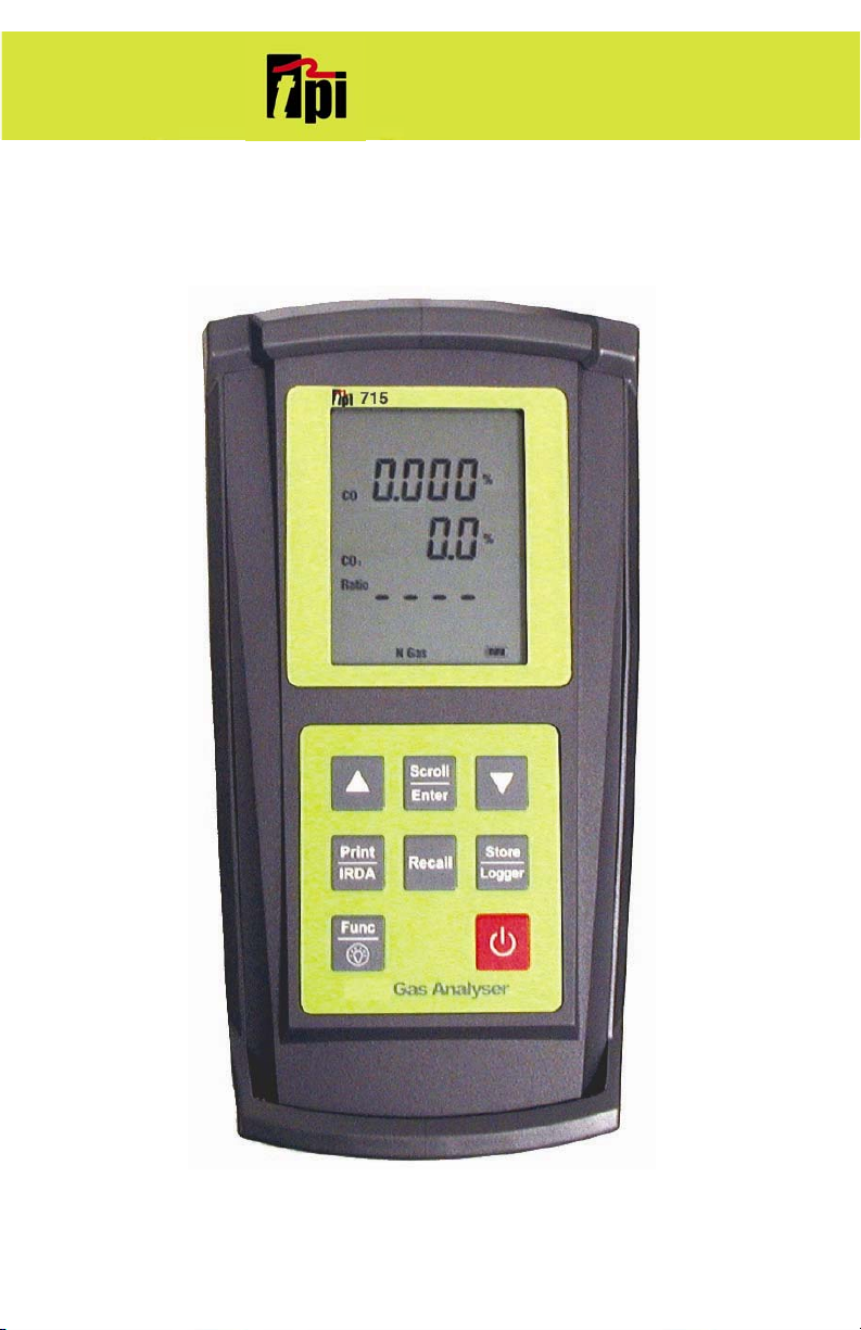
TPI 715
Gas Analyzer
1
Page 2

1. Introduction
Thank you for purchasing TPI brand products. The TPI 715 Gas Analyser is a state of the art, easy to
use analyser designed not only to display and calculate the required readings from a flue but also to
cover most of the other desirable parameters associated with combustion. The instrument is
ruggedly constructed and comes with a 3 Year Guarantee.
This manual will guide you through the functions of the TPI 715 which will give you many years of
reliable service.
Your TPI 715 Gas Analyser comes complete with the following items as standard: -
TPI 715 Instrument
Rubber Boot
Soft Carrying Case
Sampling Probe (c/w Type “K” Thermocouple)
In-Line Filter
Exhaust Spigot (removable)
Instruction Manual
Your TPI 715 Flue Gas Analyser has the following options available: -
Various Temperature Probes (see Appendix B)
Infrared Printer A740B
2
Page 3

Contents
1. Introduction
2. Instrument Overview
2.1 Front View
2.2 Back View
2.3 Side Views
2.4 Top View
3. Turning On & Off and Charging
3.1 Turning On
3.2 Turning Off
4. The 3 Functions
4.1 Function 1: - Flue Analysis
4.2 Function 2: - Temperature Reading
4.5 Function 5: - Date/Time
5. Saving Data
6. Reviewing Data
7. Printing Data
Appendix A Specifications
Appendix B Calibration & Service
Appendix C Guarantee
Appendix D Troubleshooting Guide
Appendix E Index
3
Page 4

This page left blank intentionally.
4
Page 5
2. Instrument Overview
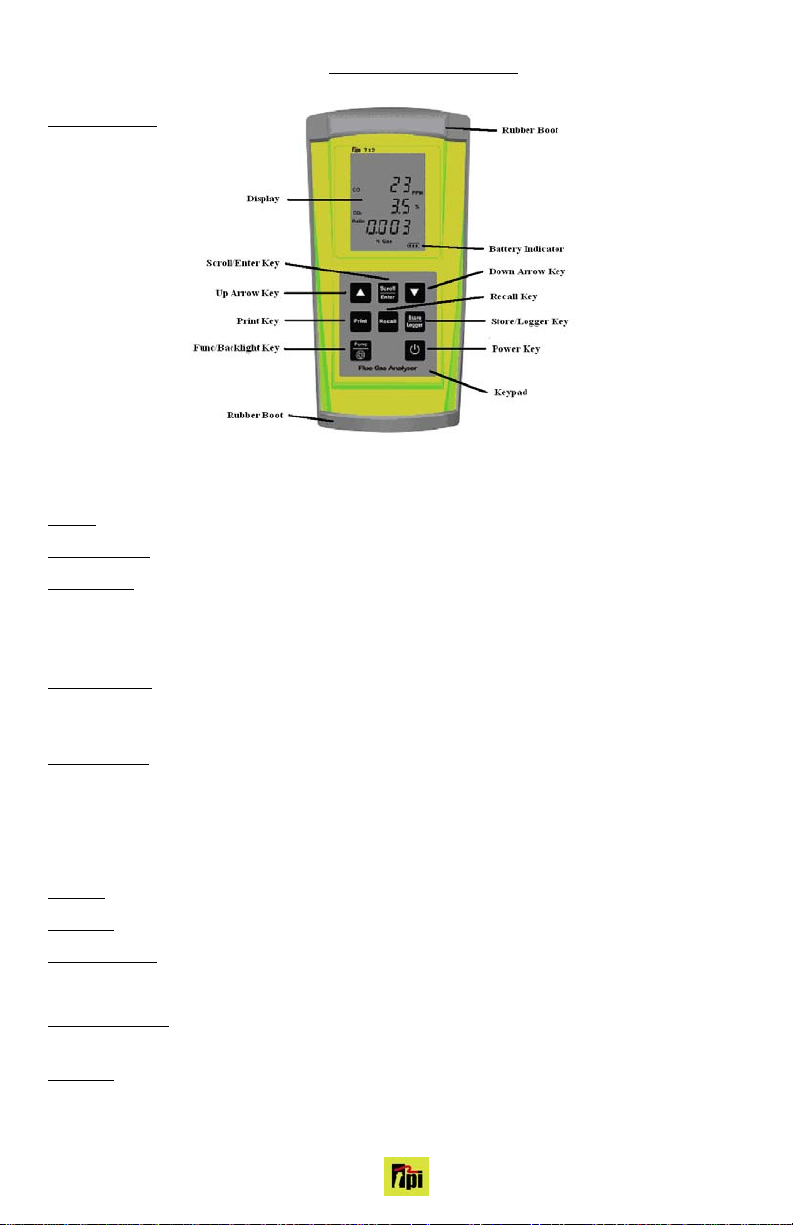
2.1 Front View
Rubber Boot Protects the instrument from accidental damage
Display Large 3 Parameter Backlit Display
Battery Indicator Showing battery life
Up Arrow Key Scrolls through selectable fuels (see 3.1 )
Switches between Gross and Nett Efficiency (see 4.1.2)
Switches between ºC and ºF (see 4.2.1)
Moves up through the Stored Data Addresses (see 5, 6 & 7)
Down Arrow Key Zeroes pressure reading (see 4.3.1)
Moves down through the Stored Data Addresses (see 5, 6 & 7)
Decreases data logging time intervals (see 8)
Scroll/Enter Key Scrolls through Gas Analysis Function Screens (see 4.1)
Turns temperature differential calculation ON/OFF (see 4.2.1)
Turns ch2 temperature ON/OFF (see 4.3.1)
Allows you to change the Date and Time (see 4.5)
Allows you to choose a Stored Data Address (see 5, 6, 7, & 8)
Print Key
Sends stored or real time data to a separate infrared printer (see 7)
Recall Key Allows you to view stored data on the display (see 6)
Store/Logger Key Stores readings to memory (see 8)
Starts and Stops data logging (see 8)
Func/Backlight Key Moves you through the 3 Functions (see 4)
Turns Backlight ON and OFF (see 4)
Power Key Turns the instrument ON and OFF (see 3.1 & 3.2)
5
Page 6
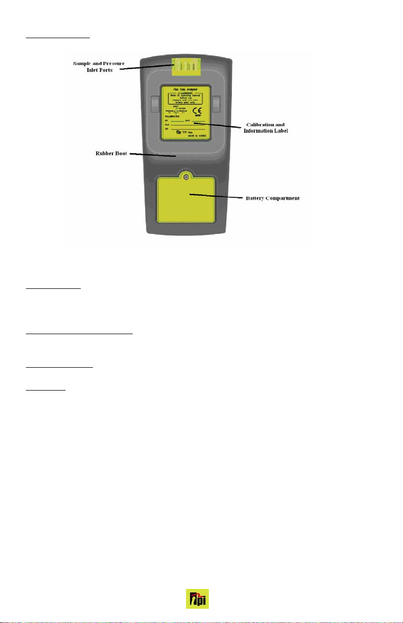
2.2 Back View
Sample Inlet Port Connection for Gas Sampling Probe (see 2.4 & 4.1)
Calibration and Information Label
Displays serial number
Battery Compartment
Rubber Boot
Holds 4 AA batteries
Protects the instrument from accidental damage
Displays calibration information
6
Page 7
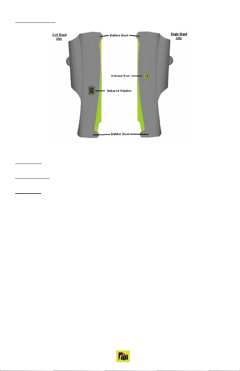
2.3 Side Views
Exhaust Port
Infrared Window
Rubber Boot
Port for connection of Exhaust Adaptor
Protects the instrument from accidental damage
Window for sending stored data to IR Printer or PC (see 7 & 9)
7
Page 8
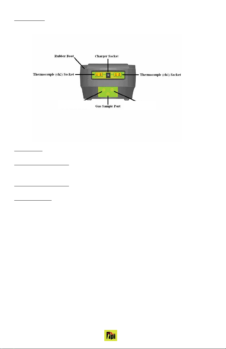
2.4 Top View
Power Socket
Connection for 12V Car Adapter (see 3.3)
Thermocouple (ch1) Socket
Connection for thermocouple plug on probe (see 4.1)
Connection for any ‘K’ type thermocouple probe (see 4.2)
Thermocouple (ch2) Socket
Connection for any ‘K’ type thermocouple probe (see 4.2)
Gas Sampling Port
Connection for In-Line Filter for Gas Leak Detection (see 4.4)
Connection for Gas Sampling Probe (see 4.1)
8
Page 9

3. Turning On &Off
3.1 Turning On
Always: - Before turning on please ensure that the Temperature Sampling Probe complete with InLine Filter is not connected to the Gas Sample Port (see 2.2 or 2.4)
Press the Power Key and the TPI 715 will start its 30 second countdown purge ‘PURGING’ will be
displayed: - The instrument should be turned on in a clean air environment as the 30 second purge
will set the Carbon Monoxide level to Zero and the Oxygen to 20.9%.
Ensure that the filters are clean and dry as dirty or wet filters will result in a loss of flow rate and ‘Lo
Flo’ will be displayed to inform you that filters should be changed
During the last 20 seconds of the 30 second purge time the user can scroll through the following
Fuels: - Natural Gas, LPG, Light Oil, Heavy Oil, Bituminous Coal, Anthracite Coal, Coke, Butane,
Wood (Dry), and Bagasse by pressing the Up Arrow Key to select the Fuel they are working with.
When desired fuel is displayed release the key, displayed fuel is now selected.
Fuel LCD Display Print Display
Natural Gas Natural Gas Natural Gas
Light Oil Light Oil Light Oil
Heavy Oil Heavy Oil Heavy Oil
LPG LPG LPG
Bituminous Coal Fuel , OPT 1 Bituminous Coal
Anthracite Coal Fuel , OPT 2 Anthracite Coal
Coke Fuel , OPT 3 Coke
Butane Fuel , OPT 4 Butane
Wood (Dry) Fuel , OPT 5 Wood (Dry)
Bagasse Fuel , OPT 6 Bagasse
NOTE: When selecting oil
as fuel be sure to use the
optional oil filter to prolong
the life of the sensors.
After the 30 second countdown the instrument is ready to take Flue, Temperature readings and will
Display Screen 1 from Function 1 as described in The 3 Functions Section (see 4.1.1)
3.2 Turning Off
Always: - Before turning off return the instrument to a clean air environment and allow the Carbon
Monoxide level to return to below 15ppm and the Oxygen level to return to 20.9% (± 0.3%)
Press the Power Key to turn the instrument off:- NOTE Should you attempt to turn the instrument
Off and the CO reading is above 0.003% then the instrument will remain On and a short Beep will
be heard. The Instrument can only be switched off if the CO is below 0.003%
The instrument has an auto shut off after 10mins should no keys have been pressed for
this period and as mentioned above that the CO is below 0.003%. Should the CO be above
0.003%then the 10 minute auto shut off countdown will not begin till the CO has gone below
0.003%
9
Page 10

4. THE FUNCTIONS
You can move through the following functions by pressing the Func/Backlight Key
At any time you can activate the Backlight by holding down the Func/Backlight Key for 2 seconds.
4.1
Function 1: - Gas Analysis
Ensure you have connected the Temperature Flue Sampling Probe complete with In-Line Filter
to the Gas Sample Port (see 2.2 or 2.4) and the ‘K’ Type Thermocouple Plug into Thermocouple (ch1) Socket (see 2.4). as well as the ‘K’ Type wire probe for measuring the combustion air temperature into ch2 socket (see 2.4).
WARNING: taken, particularly if water is visible. Failure to comply may result in damage to the instrument.
WARNING: - There is ONLY one correct way to connect the ‘K’ type thermocouple plug into the
socket (see 2.4). Forcing the plug into the socket the wrong way round may result in damage to the
instrument.
You can move through the following Screens by pressing the Scroll/Enter Key: -
4.1.1 Screen 1 Displays Carbon Monoxide (CO) reading in percent (%)
Displays calculated Carbon Dioxide (CO
Displays calculated CO/CO
4.1.2 Screen 2
Displays calculated Excess Air (X Air) figure in percentage (%)
Displays calculated Efficiency (Eff.) figure in percentage (%)
Pressing the Up Arrow Key will toggle between Gross & Nett Efficiency
4.1.3 Screen 3
Displays Oxygen (O
Displays NOx reading in parts per million (ppm)
4.1.4 Screen 4
Displays Temperature reading of Channel 2 (ch2) in degrees Centigrade (ºC)
Displays the Differential Temperature (Diff.) between ch1 and ch2 in ºC
‘oPEn’ will be displayed if no ‘K’ type probe is connected to the thermocouple socket
4.1.5 Screen 5
Displays NOx readings in parts per million (ppm)
Ensure that the In-Line Filter hangs in a vertical position whilst readings are being
) figure in percentage (%)
2
(Ratio) figure
2
Displays Oxygen (O2) reading in percentage (%)
Displays Carbon Monoxide (CO) reading in parts per million (ppm)
) reading in percentage (%)
2
Displays Temperature reading of Channel 1 (ch1) in degrees Centigrade (ºC)
Displays NO readings in parts per million (ppm)
10
Page 11

4.2 Function 2: - Temperature Reading
Ensure you have a ‘K’ type probe connected to one or both of the thermocouple sockets ch1
or ch2 (see 4.2)
WARNING: the socket (see 4.2). Forcing the plug into the socket the wrong way round may result in damage to
the instrument.
The pump will stop running when in this function
4.2.1 Screen 1
Pressing the Up Arrow Key will toggle between ºC and ºF
Displays Temperature reading of Channel 1 (ch1) in degrees Centigrade (ºC) or degrees Fahrenheit (ºF)
Displays Temperature reading of Channel 2 (ch2) in degrees Centigrade (ºC) or degrees Fahrenheit (ºF)
Pressing the Scroll/Enter Key will toggle the Differential Temperature ON and OFF
Displays the Differential Temperature (Diff.) between ch1 and ch2 in ºC or ºF
‘oPEn’ will be displayed if no ‘K’ type probe is connected to the thermocouple socket
There is ONLY one correct way around to connect the ‘K’ type thermocouple plug into
11
Page 12

4.5 Function 5: - Date/Time
The Time, Date and Year can be changed whilst in this function as below:-
4.5.1 Screen 1
Displays the current Time, Date and Year
Press the Scroll/Enter Key once to allow you to change the Time, Date and Year
Press the Up Arrow Key to Increase the Minutes
Press the Down Arrow Key to Decrease the Minutes
Press the Scroll/Enter Key to confirm the desired Minute and move onto the Hours
Repeat steps 2 to 4 to change the Hour, the Day, the Month and the Year
The unit will return to normal after the desired Year has been confirmed
12
Page 13

5. SAVING DATA
Press the Store Key once
‘Save’ will be displayed on the top line along with ‘Addr SA ’ and a location number from 0 to 9 will
be flashing on the screen.
Select the required address location that you wish to save the data to by pressing the Up and
Down Arrow Keys
Press the Scroll/Enter Key once
The location number which you have chosen will stop flashing and after about 2 seconds the instrument will return to the screen/function you were previously on.
You have just successfully stored a set of readings which can be either reviewed on screen
(see 6) or sent to the IR printer (see 7)
6. REVIEWING DATA
Press the Recall Key once
‘Stor’ will be flashing on the display
Press the Scroll/Enter Key once
‘Addr SA ’ will be displayed and a location number from 0 to 9 will be flashing.
Select the required address location that you wish to review the saved data from by pressing
the Up and Down Arrow Keys
Press the Scroll/Enter Key once
The Time & Date of the Saved Data from the selected address location will be displayed flashing on
the screen.
The rest of the Saved Data at this address location can be reviewed by pressing the Up and
Down Arrow Keys
Press the Scroll/Enter Key once ‘End’ will be displayed with ‘YES’ flashing
Press the Scroll/Enter Key once to EXIT
or
Press the Up or Down Arrow Keys ‘End’ will be displayed with ‘no’ flashing
Press the Scroll/Enter Key once to CHOOSE another address location to review and repeat
steps 2 to 5
13
Page 14

7. PRINTING DATA
1. Press the Print Key once
‘Print & IR’ will be displayed on the top line along with ‘Stor’ flashing on the screen with
“REAL” also on the display.
You can choose to print stored readings which have been already saved (Stor) or select “REAL” by
pushing the up arrow button so that the “REAL” is flashing you can print the current realtime readins
on the display.
Press the Scroll/Enter Key once
‘Addr SA ’ will be displayed and a location number from 0 to 9 will be flashing.
Select the required address location that you wish to print the saved data from by pressing
the Up and Down Arrow Keys
Press the Scroll/Enter Key once
‘Print, Wait, Send & IR’ will be displayed on the top line along with ‘out’ on the screen
WARNING: on the instrument (see 2.3) and the Infrared Window on the IR Printer (see Printer instructions)
After all the saved data has been sent to the printer ‘End’ will be displayed with ‘YES’ flashing
Press the Scroll/Enter Key once to EXIT
or
Press the Up or Down Arrow Keys
‘End’ will be displayed with ‘no’ flashing
Press the Scroll/Enter Key once to CHOOSE another address location to print and repeat
steps 2 to 4
To operate correctly there must be a clear line of sight between the Infrared Window
14
Page 15

This page left blank intentionally.
15
Page 16

Appendix A : SPECIFICATIONS
Instrument
Operating Temperature Range -10˚C to +50˚C
Battery 4 AA Alkaline Batteries
Battery Life > 6 Hours
Fuels Natural Gas, LPG, Light Oil, Heavy Oil & User Defined
Display Backlit LCD
Data Storage 10 sets of readings
Time & Date 24 Hour Real Time Clock
Dimensions 200mm x 90mm x 60mm
Weight 500g
Casing Rubber Boot as Standard
Switch Off Failsafe
Exhaust Safety Spigot
Conforms to BS7927 (and the draft BS7967)
Flue Temperature Probe
Construction Pistol Grip with Stainless Steel Shaft
Hose Length 2500mm
Insertion Length 200mm
‘K’ Type Thermocouple Accuracy +/- 0.3%, +/- 1˚C
Maximum Temperature 800˚C
16
Page 17

Gases
Range
Oxygen 0-25% 0.1% +/- 0.3%
Carbon Monoxide 0-10 % +/-0.001 % <20 ppm : +/- 3 ppm
>100 ppm : +/- 5 %
Nitrogen Oxide 0-5,000 ppm 1 ppm +/- 3 ppm
NOx 0-5,000 ppm 1 ppm calculated
Carbon Dioxide (calculated) 0-25% 0.1% +/- 0.3%
CO/CO
Ratio (calculated) 0-0.999 0.001
2
Combustion Efficiency 0-100% 0.1%
Resolution Accuracy
17
Page 18

Appendix B : CALIBRATION & SERVICE
It is recommended that the instrument be calibrated every 12 months. Please consult Test Products
International for further details.
Appendix C : GUARANTEE
Your TPI 715 Gas Analyser is guaranteed free from defects in materials and workmanship for 3
Years from the date of purchase.
Covered by TPI: - Repair parts and labour; or replacement of the product at the option of TPI.
Normal transportation charges to the purchaser are also covered.
Not covered by TPI: - Damage to the product which are the result of abuse, improper use or maintenance are not covered. Any other expenses, consequential damages, incidental expenses including damages to property are not covered. Transportation expenses to the customer are not covered.
To obtain warranty performance: - Include with the product your name, address, phone number,
written description of the problem and proof of purchase date. Carefully package and return to TPI.
This guarantee does not affect your statuary rights.
18
Page 19

This page left blank intentionally.
19
Page 20

Appendix E : INDEX
Subject Section
Alarm (Failsafe) 3.2
Auto-Shut Off 3.2
Backlight 4
Back View 2.2
Battery Charger 1 & 3.3
Battery Indicator 2.1
Calibration Appendix B
Charger Socket 2.4
Charging 3.3
Clock 4.5
CO 4.1.1 & Appendix A
CO
2
Data (Downloading) 9
Data (Printing) 7
Data (Reviewing) 6
Data (Saving) 5
Dimensions Appendix A
Display 2.1 & Appendix A
Efficiency (Nett & Gross) 4.1.2
Excess Air 4.1.2
Exhaust Port 2.3
Filters Appendix B
Front View 2.1
Fuel Selection 3.2
Fuels 3.2 & Appendix B
Func/Backlight Key 2.1 & 4
Guarantee Appendix C
Infrared Printer 1, 7 & Appendix B
Infrared Window 2.3 & 7
Inlet Ports 2.2 ; 2.4 ; 3.1 ; 4.1 ; 4.3 & 4.4
In-Line Filter 1 ; 3.1 ; 4.1 & Appendix B
Leak Detection 4.4
Low Flow 3.1
Mini In-Line Filter 1 ; 3.1 ; 4.4 & Appendix B
O
2
Off 3.2
On 3.1
4.1.1 & Appendix A
4.1.2 ; 4.1.3 & Appendix A
20
Page 21

Appendix E : INDEX continued
Subject Section
‘oPEn’ 4.1.4
Operating Temperature Appendix A
Power Key 2.1 ; 3.1 & 3.2
Pressure Selections 4.3.1 & Appendix A
Print Key 2.1 & 7
Probes 1 ; 4.1 ; 4.2 ; Appendix A & Appendix B
Pump 3.1
Purging 3.1
Ratio 4.1.1
Reading (Flue Gases) 4.1
Reading (Pressure) 4.3
Reading (Temperature) 4.2
Recall Key 2.1 & 6
Rubber Boot 1 ; 2.1 ; 2.2 ; 2.3 ; 2.4, Appendix A & Appendix B
Scroll/Enter Key 2.1 ; 4.1 ; 4.2.1 ; 4.3.1 ; 4.5.1 ; 5 ; 6 ; 7 & 8
Service Appendix B
Side Views 2.3
Specifications Appendix A
Store/Logger Key 2.1 & 8
Temperature Selections 4.2
Thermocouple 2.4 ; 4.1 ; 4.2 ; Appendix A & Appendix B
Top View 2.4
Troubleshooting Appendix D
Up Arrow Key 2.1 ; 3.1 ; 4.1.2 ; 4.2.1 ; 4.3.1 ; 4.5.1 ; 5 ; 6 ; 7 & 8
Warranty Appendix B
Weight Appendix A
21
Page 22

Trouble Shooting Guide
Problem Solution
Unit will not turn on Battery voltage is low, change batteries.
Unit will not turn off The CO level is above 0.030% and the failsafe will not
allow the unit to shut off, wait for CO levels to drop and
then shut off.
Can not print saved readings -Make sure the infrared eyes are aligned on the printer
and the 715
-Make sure the lights on the printer are not flashing if
so batteries need to be replaced
Wrong readings are on the printout -Make sure you are selecting the correct location to
print, if saved in “location 1” print “location 1”
-Make sure you are not selecting REAL time print mode
22
Page 23

APPLICATION NOTES:
23
Page 24

Visit TPI, The Value Leadertm at:
www.tpi-thevalueleader.com
Test Products International, Inc.
Headquarters:
9615 SW Allen Blvd.
Beaverton, OR 97005
USA
503-520-9197 • Fax: 503-520-1225
e-mail: info@tpi-thevalueleader.com
24
Test Products International, Ltd.
342 Bronte St. South Unit #9
Milton, Ontario L9T 5B7
Canada
905-693-8558 • Fax: 905-693-0888
e-mail: info@tpicanada.com
Test Products International UK Ltd.
Longley House, East Park
Crawley, West Sussex RH10 6AP
England
Tel: +44 (0)1293 561212
Fax: +44 (0)1293 813465
e-mail: info@tpi-uk.com
715MANUAL © 2002
 Loading...