

Page 1
TPI 712BT
Flue Gas Analyser
Page 2

Page 3

Contents
1. Introduction
2. Instrument Overview
2.1 Front View
2.2 Back View
2.3 Side Views
2.4 Top View
3. Turning On & Off and Charging
3.1 Turning On
3.2 Turning Off
3.3 Charging
4. The 5 Functions
4.1 Function 1: - Flue Gas Analysis & CO Build Up Test
4.2 Function 2: - Temperature Reading
4.3 Function 3: - Pressure Testing & Tightness Test
4.4 Function 4: - Leak Detection
4.5 Function 5: - Date/Time
5. Saving Data
6. Reviewing Data
7. Printing Data
8. Timed Logging
9. Downloading Data to a PC
10. Turning Off & Charging
Appendix A Specifications
Appendix B Calibration & Service
Appendix C Guarantee
Appendix D Troubleshooting Guide
Appendix E Index
Page 4

1. Introduction
Thank you for purchasing TPI brand products. The TPI 712BT Flue Gas Analyser
is a state of the art, easy to use analyser designed not only to display and
calculate the required readings from a flue but also to cover most of the other
desirable parameters associated with combustion. The instrument is ruggedly
constructed and comes with a limited 3 Year Warranty
This manual will guide you through the functions of the TPI 712, which will give
you many years of reliable service. The TPI 712 software has in-built selfdiagnostics that can easily be interrogated by our fully qualified and professional
engineers should an error occur. Please call the number below before returning
your instrument to your distributor should an error occur. We can rectify over 75%
of proposed faults over the phone.
TPI HELPLINE
01293 530196
Your TPI 712BT Flue Gas Analyser comes complete with the following items as
standard: -
• TPI 712BT Instrument
• Rubber Boot
• Soft Carrying Case
• Sampling Probe (c/w Type “K” Thermocouple)
• In-Line Water Trap Bowl Filter (c/w Spare Particle Filter)
• Battery Charger
• Mini In-Line Pump Protection Filter (c/w 5 spare filters)
• Exhaust Spigot (removable)
• Pressure Tubing (2 x 1 metres)
• GK11M Air Probe
• Instruction Manual
Your TPI 712BT Flue Gas Analyser has the following options available: -
• Infrared Printer (see Appendix )
• Various Temperature Probes (see Appendix B)
Page 5
2. Instrument Overview
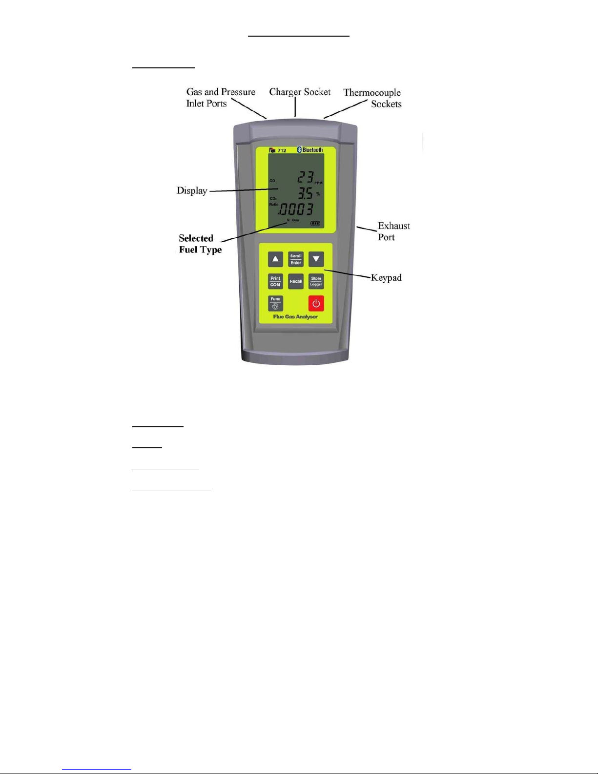
2.1 Front View
Rubber Boot
Protects the instrument from accidental damage
Display
Large 3 Parameter Backlit Display
Battery Indicator
Showing battery life
Selected Fuel Type
N Gas, LPG, L Oil, Heavy Oil, OPT (1~6) (See 3.1)
Page 6
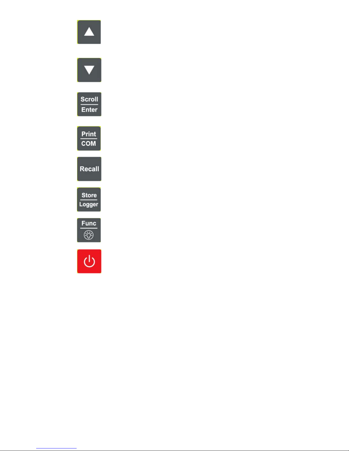
Scrolls through selectable fuels (see 3.1 )
Switches between Gross and Nett Efficiency (see 4.1.2)
Switches between ºC and ºF (see 4.2.1)
Scrolls through mbar, kPa and inH
2
O (see 4.3.1)
Moves up through the Stored Data Addresses (see 5, 6 & 7)
Increases data logging time intervals (see 8)
Zeroes pressure reading (see 4.3.1)
Moves down through the Stored Data Addresses (see 5, 6 & 7)
Decreases data logging time intervals (see 8)
Scrolls through Flue Gas Analysis Function Screens (see 4.1)
Turns temperature differential calculation ON/OFF (see 4.2.1)
Turns ch2 temperature ON/OFF (see 4.3.1)
Allows you to change the Date and Time (see 4.5)
Allows you to choose a Stored Data Address (see 5, 6, 7, & 8)
Sends stored data to a separate infrared printer (see 7)
Sends real time, stored or logged data to a PC (see 9)
Allows you to view stored data on the display (see 6)
Stores readings to memory (see 8)
Starts and Stops data logging (see 8)
Moves you through the 5 Functions (see 4)
Turns Backlight ON and OFF (see 4)
Turns the instrument ON and OFF (see 3.1 & 3.2)
Page 7
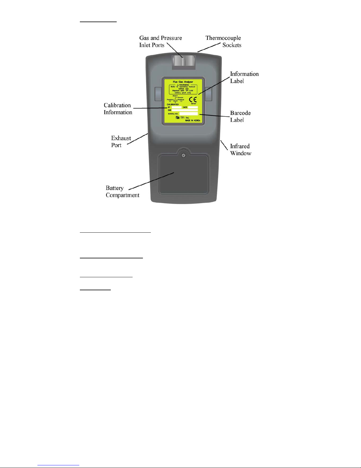
2.2 Back View
Gas and Pressure Inlet Ports
Connection for In-Line Pump Protection Filter
(see 2.4 & 4.4)
Connections for Pressure Tubing (see 2.4 & 4.3)
Calibration and Info Label
Displays calibration information
Displays serial number
Battery Compartment
Holds rechargeable battery
Rubber Boot
Protects the instrument from accidental damage
Page 8

2.3 Side Views
Exhaust Port
Port for connection of Exhaust Adaptor
Infrared Window
Window for sending stored data to IR Printer (see 7)
Rubber Boot
Protects the instrument from accidental damage
Page 9

2.4 Top View
Charger Socket
Connection for 220V/115V charger (see 3.3)
Thermocouple (ch1) T1 Socket
Connection for thermocouple plug on probe
(see 4.1)
Connection for any ‘K’ type thermocouple probe
(see 4.2)
Thermocouple (ch2) T2 Socket
Connection for any ‘K’ type thermocouple probe
(see 4.2)
Gas Inlet Port
Connection for In-Line Pump Protection Filter for
(see 4.4)
Pressure (+) Port
Connections for Pressure Tubing (see 4.3)
Pressure (-) Port
Connections for Pressure Tubing (see 4.3)
Page 10
3. Turning On & Fuel Selection
3.1 Turning On
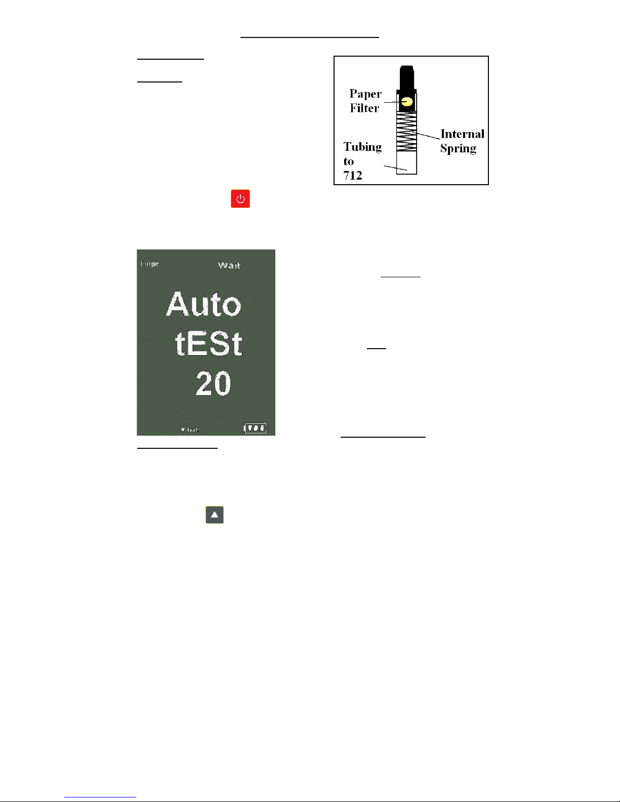
Always: - Before turning on please ensure
that the
In-Line Pump Protection Filter
(shown across) is connected to the Gas
Sample Port (see 2.2 or 2.4).
**THIS MUST REMAIN ON THE UNIT
AT ALL TIMES.**
Failure to do so may result in pump failure
and will invalidate the warranty.
Press the Power Key for approximately 2 seconds and the TPI 712 will start
up and display ALL Segments on the display for approx. 1 second. The 712 will
then enter its 30-second purge period countdown with the following screen being
displayed.
The instrument should ALWAYS be turned on
in a clean air environment as the 30 second
purge will attempt to set the Carbon Monoxide
level to 0 ppm and the Oxygen to 20.9%.
If there is insufficient clean air in the sensor
chamber after the 30 second purge period an
error indicating this may
be displayed, please
see troubleshooting guide (appendix D) for
appropriate remedy. If the error is still present
after attempting the suggested remedy please
call the
TPI HELPLINE
01293 530196
3.2 Fuel Selection
During the last 20 seconds of the 30 second purge time (i.e. as the 712 counts
down from 19 to 0) the user can scroll through the following Fuels: - Natural Gas,
LPG, Light Oil, Heavy Oil & OPT 1-6 (1=Bituminous Coal, 2=Anthracite Coal,
3=Coke, 4=Butane, 5=Wood(Dry) & 6=Bagasse) by repeatedly pressing the
Up Arrow Key to select the Fuel they are working with.
Page 11
4. THE 5 FUNCTIONS
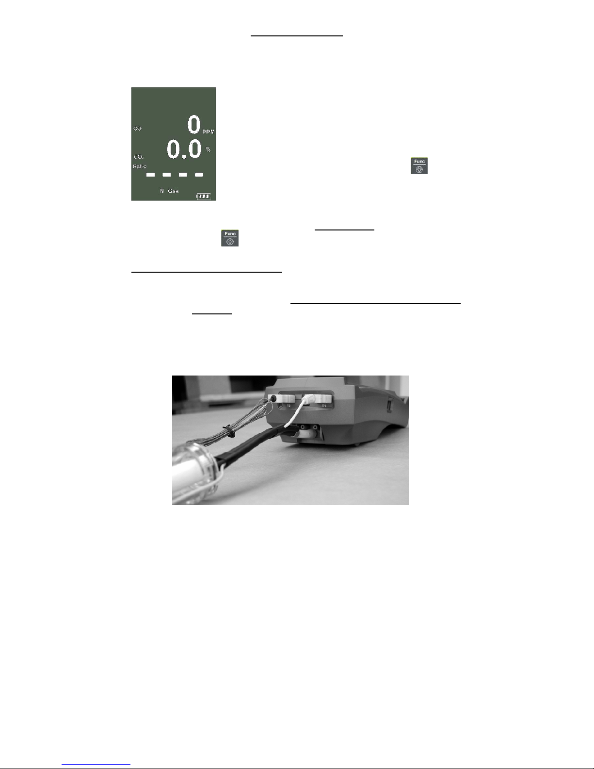
After the 30-second countdown the instrument is ready to take Flue Gas,
Temperature, Pressure or Leak Detection readings and will Display the
following Screen.
You are now ready to take Flue Gas Analysis
Readings. Please continue on with the manual from
Section 4.1 (below) which will guide you through the
various Analysis Screens.
However, if you do not wish to perform a Flue Test at
this moment Press the Func/Backlight Key
and move onto Section 4.2 of the manual.
At any time you can activate the Backlight by holding down
the
Func/Backlight Key for 2 seconds.
4.1 Function 1: - Flue Gas Analysis
Ensure you have connected the Temperature Sampling Probe complete with
In-Line Water Trap Bowl Filter to the In-Line Pump Protection Filter (See 3.1)
which should ALWAYS be connected to the Gas Sample Port (see 2.2 or 2.4)
and that the ‘K’ Type Thermocouple Plug is in Thermocouple Socket (ch1)
(see 2.4). Also ensure that a ‘K’ Type Air Probe is connected to
Thermocouple Socket (ch2) (see 2.4) in order to calculate efficiency.
Page 12
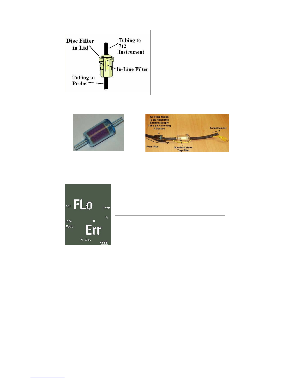
Your temperature-sampling probe comes complete with an In-Line Water Trap
Bowl Filter as standard.
This consists of a Particle Filter in the
Bowl Compartment and a Disc Filter
in the Lid (as shown in the diagram
across). The Disc Filter in Lid will
prevent any excessive water from
entering the 712 Flue Gas Analyser if
used correctly.
If you are working with OIL then you MUST
ensure that you also use the optional
Oil Filter as shown below. Failure to do so will result in erroneous readings.
If any of the filters
become excessively dirty or blocked then the
following screen will be displayed as a warning and no further
readings will be able to be taken until either the dirty filters are
replaced or the blockage removed:-
The 712 will also give off an audible Beeping Alarm
to warn that a “FLo Err” is being detected
Page 13

WARNING: - Ensure that the In-Line Water Trap Bowl Filter hangs in a vertical
position whilst readings are being taken, particularly if water is visible (see below).
Failure to comply may result in damage to the instrument and will invalidate
the warranty.
WARNING: -
There is ONLY one correct way to connect the
‘K’ type thermocouple plug into the socket (see 2.4). The
thermocouple plug is designed with one thick (negative) and
one thinner (positive) prong. Forcing the plug into the socket
the wrong way round may result in damage to the instrument.
Failure to comply may result in damage to the instrument
and will invalidate the warranty.
Pressing the Scroll/Enter Key will take you through the following Flue Gas
Analysis Screens
4.1.1 Screen 1
Displays Carbon Monoxide (CO) reading in parts per
million (ppm)
Displays calculated Carbon Dioxide (CO
2
) figure in
percentage (%)
Displays calculated CO/CO
2
(Ratio) figure
Page 14

4.1.2 HIGH CO ALARM
Should the CO reading rise above 2,000ppm a continuous series of Alarm Beeps
will be heard. If this occurs then the Probe should immediately be disconnected
from the instrument and the instrument returned to a clean air environment. This
Alarm alerts the user that there is a high concentration of CO, and this procedure
will protect the sensors within the instrument.
Failure to comply may result in damage to the instrument and will invalidate
the warranty.
4.1.3 Screen 2
Displays Oxygen (O
2
) reading in percentage (%)
Displays calculated Excess Air (X Air) figure in
percentage (%)
Displays calculated Efficiency (Eff.) figure in percentage
(%)
Pressing the Up Arrow Key will toggle between
Gross & Nett Efficiency
4.1.4 Screen 3
Displays Carbon Monoxide (CO) reading in parts per
million (ppm)
Displays Oxygen (O
2
) reading in percentage (%)
Page 15

4.1.5 CO Build Up Feature
Whilst on Screen 3 of the Combustion Screens (see 4.1.3) press and HOLD the
Store/Logger Key until the 712 beeps and the following screen is
displayed:-
“S-L9” will be flashing. Press the Scroll/Enter Key
and choose an address location by pressing the
Up & Down Arrow Keys.
When an address location (0-4) has been
chosen press the
Scroll/Enter Key to start the CO
logging session.
The 712 will return to the previous screen and “Logger” will be flashing at the top
of the display. The instrument will now log the CO level every minute for the next
30 minutes and store the results in the chosen address location.
You can end the CO logging at any point by pressing and holding down the
Store/Logger Key.
Both the Maximum and Average CO readings will be stored during this test.
These readings can then be either Printed to a compatible IR Printer (see 7) or
Downloaded to a compatible PC (see 9)
4.1.6 Screen 4
Displays CO air free calculated reading
Page 16

4.1.7 Screen 5
Displays Temperature reading of Channel 1 (ch1) in
degrees Centigrade (ºC)
Displays Temperature reading of Channel 2 (ch2) in
degrees Centigrade (ºC)
Displays the Differential Temperature (Diff.) between ch1
and ch2 in ºC
‘oPEn’ will be displayed if no ‘K’ type probe is
connected to the thermocouple socket
4.1.8 CO above 15ppm (Failsafe) Protection Beep
The 712 will not allow the user to either Turn the instrument OFF or to move to
another Function whilst the CO level is above 15ppm. A short beep will be heard
should the user attempt either of the above with the CO above 15ppm.
This is a Failsafe Feature of the 712 to protect the instrument from giving false
readings when next turned on. The 712 should be run in a clean air environment
with just the In-Line Pump Protection Filter attached until the CO level drops
below 15ppm. The 712 will then be able to be moved to a different function
screen or be turned OFF.
4.2 Function 2: - Temperature Reading
The pump will stop running when in this function
Remember:-
It was the Function Key that got you here!!!
Ensure you have a ‘K’ type probe connected to one or both of the
thermocouple sockets ch1 or ch2 (see 4.2)
Page 17

WARNING: -
There is ONLY one correct way to connect the
‘K’ type thermocouple plug into the socket (see 2.4). The
thermocouple plug is designed with one thick (negative) and one
thinner (positive) prong. Forcing the plug into the socket the
wrong way round may result in damage to the instrument.
Failure to comply may result in damage to the instrument
and will invalidate the warranty.
4.2.1 Screen 1
Displays Temperature reading of Channel 1 (ch1) in
degrees Centigrade (ºC) or degrees Fahrenheit (ºF)
Displays Temperature reading of Channel 2 (ch2) in
degrees Centigrade (ºC) or degrees Fahrenheit (ºF)
Displays the Differential Temperature (Diff.) between ch1
and ch2 in ºC or ºF
Pressing the Up Arrow Key will toggle between
ºC and ºF
‘oPEn’ will be displayed if no ‘K’ type probe is
connected to the thermocouple socket
4.3 Function 3: - Pressure Testing
The pump will stop running when in this function
Remember:-
It was the Function Key that got you here!!!
Ensure you have Pressure Sampling Tube connected to one or both of the
Pressure Ports (see 2.2 or 2.4)
Page 18

4.3.1 Screen 1
Displays Pressure reading in either millibars (mbar),
kiloPascals (kPa), or inches of Water (inH
2
O)
Pressing the Up Arrow Key will scroll through
mbar, kPa and inH
2
O
Pressing the Down Arrow Key will Zero the
Pressure reading
Pressing the Scroll/Enter Key will toggle the ch2
temperature reading ON and OFF
Pressure Resolution
The pressure resolution can be toggled between 0.01mbar & 0.1mbar by pressing
and holding down both the Up & Down Arrow Keys simultaneously.
4.3.2 Tightness Test Feature
Whilst on Screen 1 of the Pressure Screen (see 4.3.1) press the
Store/Logger Key and the following screen will be displayed:-
“Stor” will be flashing. Press the Up Arrow Key
and “tItn” will be flashing.
Choose the Tightness Test Feature
by pressing the Scroll/Enter Key.
Choose an address location (0-49) by
pressing the
Up & Down Arrow Keys.
When an address location (0-49) has
been chosen press the
Scroll/Enter Key to start the
Tightness Test.
Page 19

When the Tightness Test starts the
Live Pressure Reading is displayed on the top line,
tItn on the middle line
and the Timer on the bottom line.
Once the timer reaches 1 minute it will start to flash.
After the correct stabilisation period has elapsed press
the Scroll/Enter Key
The Start Pressure will be stored and displayed on the
middle line.
The Timer will continue to count up with the
Live Pressure Reading still being displayed on the top
line.
Once the required test period has elapsed press the
Scroll/Enter Key
The Stop Pressure Reading will be stored and
displayed on the bottom line.
The Start Pressure Reading will be displayed on the
middle line and both will be flashing.
The timer will stop with the Live Pressure Reading
being displayed on the top line.
Page 20

Press the Scroll/Enter Key and “End YES” with
“YES” flashing will be displayed.
To end the Tightness Test Feature press the
Scroll/Enter Key and you will be returned to
Screen 1 of the Pressure Screen (see 4.3.1).
However if you wish to continue and perform another
Tightness Test then press the Up Arrow Key so
that “no” is flashing and press the
Scroll/Enter Key.
The information stored during the Tightness Test Feature can be either Reviewed
on the screen (see 6), Printed to a compatible IR Printer (see 7) or Downloaded to
a compatible PC (see 9)
4.4 Function 4: - Leak Detection
The pump will start running in this function with a 25 second countdown
Remember:-
It was the Function Key that got you here!!!
Ensure you have the In-Line Pump Protection Filter connected to the Gas
Sample Port (see 2.2 or 2.4) and that the instrument is in a clean air
environment.
PLEASE ENSURE THAT THE MINI IN-LINE PUMP PROTECTION FILTER IS IN
PLACE AT ALL TIMES WHILST IN ALL
FUNCTIONS.
Page 21

4.4.1 Screen 1
During 25 second purge period “LEAK” is displayed on
the screen.
It is not uncommon for the 25 second purge period to be
repeated. This may happen to give the sensor sufficient
time to warm up before readings can be taken.
Displays and Sounds an indication to the level of
Flammable Gas detected as follows: -
Value on Screen Value of Flammable Gas Tone Sounded
0 < 100ppm No Tone
1 > 100ppm but < 1,000ppm Long Pitched Tone
2 > 1,000ppm but < 5,000ppm Medium Pitched Tone
3 > 5,000ppm Short Pitched Tone
4.5 Function 5: - Date/Time
The Time, Date and Year can be changed whilst in this function as below:-
4.5.1 Screen 1
1. Press the Scroll/Enter Key once to allow
you to change the Time, Date and Year
2. Press the Up Arrow Key to Increase the
Minutes
3. Press the Down Arrow Key to Decrease
the Minutes
4. Press the Scroll/Enter Key to confirm the
desired Minute and move onto the Hours
5. Repeat steps 2 to 4 to change the Hour, the
Day, the Month and the Year
6. The unit will return to normal after the desired
Year has been confirmed
Page 22

5. SAVING DATA
In addition to the CO Build Up Test & the Tightness Test it is also possible to save
complete combustion readings, temperature and single pressure readings as
follows:-
1. Have the 712 analyser set to the relevant screen for the readings that you
wish to save (i.e. Any of the combustion screens (see 4.1) for combustion
readings or pressure screen (see 4.3.1) for single pressure reading)
2. Press the Store/Logger Key once and ‘Stor’ will be displayed on
the screen.
3. Press the Scroll/Enter Key once. ‘Addr’ will be
displayed and a location number (0 to 49) will be
flashing on the screen.
4. Select the required address location that you wish to
save the data to by pressing the Up and
Down Arrow Keys
**Please Note:- Choosing the same Address Location on which previously
Stored Data is being held will OVERWRITE
the previous readings with the
New Stored Data. This will be the case regardless of the particular readings
you are attempting to save (i.e. should you have Combustion Readings stored
at Address 1 and you Save Temperature Readings to Address 1 then the
Previous Combustion Readings will be overwritten with the New Temperature
Readings) and the previously Stored Readings will not be retrievable.
5. Press the Scroll/Enter Key once and the readings
will be stored to the location that was chosen in step 3
and “End yES” with “yES” flashing will be displayed
6. If you do not wish to save any further readings at this
moment press the Scroll/Enter Key and you will
be returned to the screen you were originally on.
7. However if you wish to continue and save another set of readings then
press the Up Arrow Key so that “no” is flashing and press the
Scroll/Enter Key.
The information that you just stored can be either be Reviewed on the screen
(see 6), Printed to a compatible IR Printer (see 7) or Downloaded to a compatible
PC (see 9)
Page 23

6. REVIEWING DATA
1. Press the Recall Key once and the following screen will be
displayed.
‘Stor’ will be flashing on the display. If you wish to review
the Tightness Test Readings or the Last Time Calibrated
Date then press the Down Arrow Key to have ‘tItn’
or ‘CAL’ flashing rather than ‘Stor’
2. Press the Scroll/Enter Key once and if you have chosen to view
the Last Time Calibrated (CAL) then the Date that the Last Time the 712
was calibrated will be displayed flashing on the screen. (Go To Step 6)
3. However if you have chosen to view either Stored (Stor)
or Tightness Test (tItn) Readings then ‘Addr’ will be
displayed and a location number will be flashing.
Select the required address location that you wish to
review by pressing the Up and Down Arrow
Keys.
4. Press the Scroll/Enter Key once and the Time & Date of the
Saved Data from the selected address location will be displayed flashing
on the screen.
**If there is no data present at that location then ‘nULL dAtA’ will be
displayed flashing**
5. The rest of the Saved Data at this address location can be reviewed
by pressing the Up and Down Arrow Keys
6. Press the Scroll/Enter Key once and “End YES”
with “YES” flashing will be displayed. Should you not
wish to view any further stored data then press the
Scroll/Enter Key once to Exit and be returned to
the screen you were originally on.
7. However if you wish to continue and review another set
of readings then press the Up Arrow Key so that “no” is flashing.
8. Press the Scroll/Enter Key once and repeat from Step 2
Page 24

7. PRINTING DATA
WARNING: -
To operate correctly there must be a clear line of sight between the
Infrared Window on the instrument (see 2.3) and the Infrared Window on the IR
Printer (see Printer instructions)
1. Press the Print/COM Key once and the following screen will be
displayed.
‘rEAL’ will be flashing.
If you wish to Print Out previously Stored (Stor) or
Tightness Test (tItn) or CO Build Up Test (S-L9)
Readings then press the Down Arrow Key to have
‘Stor’, ‘tItn’ or ‘S-L9’ flashing rather than ‘rEAL’
2. Press the Scroll/Enter Key once and if you have chosen to print out
Real Time (rEAL) readings then the ‘Print Out’ screen (below left) will be
displayed and the Real Time (rEAL) readings will be sent to the printer.
However if you have chosen to print either
Stored (Stor) or Tightness Test (tItn) or CO
Build Up Test (S-L9) Readings then ‘Addr’
will be displayed and a location number will
be flashing.
Select the required address location that
you wish to review the saved data from
by pressing the Up and Down
Arrow Keys
3. Press the Scroll/Enter Key . The ‘Print Out’ screen (above left) is
displayed and the selected readings will be sent to the printer.
4. Once the selected data has been sent to the IR printer
“End YES” with “YES” flashing will be displayed. Should
you not wish to print any further stored data then press the
Scroll/Enter Key once to Exit and be returned to the
screen you were originally on.
5. However if you wish to continue and review another set of readings then
press the Up Arrow Key so that “no” is flashing.
6. Press the Scroll/Enter Key once and repeat.
Page 25

8. TIMED LOGGING
Press and hold down the Store/Logger Key for approximately 2 seconds
until the instrument beeps an the following screen is displayed:-
‘S-L9’ will be flashing.
Press the Down Arrow Key so that ‘Lo99’ is
flashing then press the Scroll/Enter Key and follow
the steps below:-
1. ‘S-t’ will be displayed with ’05 S’ flashing indicating that the instrument
will log a set of 100 readings every 5 seconds.
You can choose from the following logging times
‘05 S’ (100 readings every 5 seconds)
‘10 S’ (100 readings every 10 seconds)
‘20 S’ (100 readings every 20 seconds)
‘30 S’ (100 readings every 30 seconds)
‘01 M’ (100 readings every 1 minute)
‘02 M’ (100 readings every 2 minutes)
‘03 M’ (100 readings every 3 minutes)
by pressing either the Up or Down Arrow Keys
2. Once you have chosen your required logging period press
the Scroll/Enter Key once and ‘PA9E’ will be
displayed.
A page number from 0 to 3 will be flashing.
Select the required page location that you wish to log
the data to by pressing the Up or Down Arrow
Keys
3. Press the Scroll/Enter Key once and the instrument will return to
the previous screen/function with ‘Logger’ flashing on the top line.
The instrument will continue logging until all 100 sets of readings
have been saved or you press and hold down the
Store/Logger Key.
The data logged during this process can ONLY be downloaded to a compatible
PC.WARNING: -
The instrument will NOT turn off if data logging is commencing.
A beep will be heard to warn you of this fact if you try to turn the instrument off.
Page 26

.
9. Connecting to a Compatible Bluetooth Device
1. Press and hold down the Print/COM Key to instruct the 712BT to search
for other Bluetooth devices. “Comm” will be displayed solid & “Wait” will
be flashing on the 712BT LCD.
2. Initiate communication with the 712BT via the relevant means on your
Bluetooth enabled PC, Laptop, XDA etc….
3. If this is the first time you have tried to connect the 712BT to your device
then you must first pair the 2 devices. On your device you will be
prompted to enter a Pairing Pin No. (Please enter the 5 digit Serial No. on
the back of the 712BT). Once the devices have been paired then there is
no need to repeat this step in the future.
4. Upon a successful connection between the 712BT and your device the
“Wait” will disappear and the “COMM” will be flashing on the 712BT
LCD. You are now ready to download the data from the 712BT to your
device.
5. Open up an appropriate program on your device such as Hyper Terminal
on a PC etc… You may need to use the following settings:-
i. Bits per second = 9600
ii. Data Bits = 8
iii. Parity = None
iv. Stop Bits = 1
v. Flow Control = None
6. You may also need to select the relevant Com Port number that was
assigned to your Bluetooth connection.
7. Press and hold down the Recall Key for approx 2 seconds. “rEAL”,
“Stor” & “tItn” will be displayed with “rEAL” flashing. The “rEAL”
flashing indicates that Real Time Data will be sent to your Device.
8. However should you wish to send either a Stored Set of Readings,
Tightness Test, CO Build Up Test or Logged Data then press the Down &
Up Arrow Keys until the desired ‘Stor’, ‘tItn’, ‘S-L9’ or ‘Lo99’ are
flashing.
9. Once you have selected the mode of data that you wish to send to
your device press the Scroll/Enter Key once.
Page 27

10. Upon a successful transfer of data the 712BT will return to the original
screen.
11. “Comm” will remain flashing on the 712BT LCD. Should you wish to
transfer more data to your device repeat from step 7.
12. Should the connection between the 712BT and your device be lost then
go back to step 2.
Page 28

10. Turning Off & Charging
Always: -
Before turning off the TPI 712 return to a clean air environment and
allow the Carbon Monoxide level to return to below 15ppm and the Oxygen level
to return to 20.9% (± 0.3%).
Press the Power Key to turn the instrument off.
NOTE:
Should you attempt to turn the instrument Off and the CO reading is
above 15ppm then the instrument will remain On and a short Beep will be heard.
The instrument can only be switched off if the CO is below 15ppm.
The instrument has an auto shut off after 10mins should no keys have been
pressed for this period and, as mentioned above, that the CO is below 15ppm.
Should the CO be above 15ppm then the 10-minute auto shut off countdown will
not begin till the CO has gone below 15ppm.
10.1 Charging
Plug the Charger supplied into the charger socket on the instrument (see 2.4). If
the instrument is turned on then a charging symbol will be displayed. Should the
instrument then be turned off or turn off automatically with the charger plugged in
then the charging symbol will not be displayed BUT the instrument will still be
charging.
The instrument should be charged overnight for a period of 10 to 12 hours and
will give over 6 hours Operating Time.
Alternatively the instrument can be used whilst plugged into the mains
Page 29

Appendix A : SPECIFICATIONS
Instrument
Operating Temperature Range -10˚C to +50˚C
Battery Rechargeable Ni-MH
Battery Life > 6 Hours
Charger Input Voltage 115V or 230V : 50/60 Hz AC
Fuels Natural Gas, LPG, Light Oil, Heavy Oil &
OPT 1 = Bituminous Coal
OPT 2 = Anthrachite Coal
OPT 3 = Coke
OPT 4 = Butane
OPT 5 = Wood (Dry)
OPT 6 = Bagasse
Pressure Ranges mbar, kPa & inH
2
O
Display Backlit LCD
Data Storage 50 sets of readings
Data Logging 4 sets of 100 readings on Timed Interval
Logging
CO Logging 4 sets of 30 minutes of CO readings
Time & Date 24 Hour Real Time Clock
Dimensions 200mm x 90mm x 60mm
Weight 500g
Casing Rubber Boot as Standard
Switch Off Failsafe
Exhaust Safety Spigot
Conforms to BS7927 (and the draft BS7967)
Flue Temperature Probe
Construction Pistol Grip with Stainless Steel Shaft
Hose Length 2500mm
Insertion Length 200mm
‘K’ Type Thermocouple Accuracy +/- 0.3%, +/- 1˚C
Maximum Temperature 800˚C
Page 30

Gases
Range
Resolution Accuracy
Oxygen 0-25% 0.1% +/- 0.3%
Carbon Monoxide 0-10,000 ppm 1 ppm <20 ppm : +/- 3
ppm
>100 ppm : +/- 5 %
Carbon Dioxide
(calculated)
0-25% 0.1% +/- 0.3%
CO/CO
2
Ratio
(calculated)
0-0.999
Combustion Efficiency 0-100% 0.1%
Gas Leak Sensor 100-10,000
ppm
Pressure Measurement
Selectable Ranges mbar, kPa and inH
2
O
Range - 150 mbar to + 150 mbar
Resolution 0.01 mbar
Accuracy +/- 0.5% fsd
Page 31

Appendix B : CALIBRATION & SERVICE
It is recommended that the instrument be calibrated every 12 months. Please
consult your instrument supplier for further details.
The following are consumable parts for the instrument: In-Line Filter Element (pack of 10) User Replaceable Part No. A794/F
Leak Detector Mini Filter Complete User Replaceable Part No. A763
Oxygen Sensor Factory Replaceable
Carbon Monoxide Sensor Factory Replaceable
The following are accessories for the instrument: Flue Temperature Probe Standard Part No. A770
Various ‘K’ Type Probes Optional See TPI Brochure
In-Line Filter Complete Standard Part No. A794
Battery Charger Standard Part No. A766
Rubber Boot Standard Part No. A765
Infrared Printer Standard Part No. A740
Soft Carrying Case Standard Part No. A768
Exhaust Spigot Standard Part No. TBC
PC Software Optional Part No. A769
IRDA-RS232C Adaptor Optional Part No. A767
Oil Filter Complete Optional Part No. A773
Air Probe Standard Part No. GK11M
Appendix C : GUARANTEE
Your TPI 712 Flue Gas Analyser is guaranteed free from defects in materials and
workmanship for 6 Years from the date of purchase. (Subject to annual service
carried out by TPI Europe Ltd).
Covered by TPI: - Repair parts and labour; or replacement of the product at the
option of TPI. Normal transportation charges to the purchaser are also covered.
Not covered by TPI: - Damage to the product which are the result of abuse,
improper use or maintenance are not covered. Any other expenses,
consequential damages, incidental expenses including damages to property are
not covered. Transportation expenses to the customer are not covered.
To obtain warranty performance: - Include with the product your name,
address, phone number, fax number, written description of the problem and
proof of purchase date. Carefully package and return to TPI.
This guarantee does not affect your statuary rights.
Page 32

Appendix D : TROUBLESHOOTING GUIDE
Problem Probable Cause Possible Remedy
Unit does not turn on Batteries are flat Recharge batteries or run
on mains.
Unit does not turn on Dislodged battery Disconnect and Re-
connect battery
Continuous alarm
Sounds
Excessive levels of
CO are being
detected
Remove probe from flue
and run in clean air for
5/10 minutes
Negative pressure
readings on Display
Pressure tubing
connected to wrong
pressure port
Reconnect pressure tubing
to positive pressure port
rather than negative
pressure port
Negative pressure
readings on display
Either there is suction
or pressure was not
zeroed in
atmospheric air
Re-zero in atmospheric
air.
Negative temperature
readings on display
Thermocouple plug
has been plugged in
the wrong way round
Remove thermocouple
plug and plug in the
correct way round
“Flo Err” is displayed Blockage in sampling
probe or
kink/blockage in
sample tube
Check and rectify as
necessary
“Flo Err” is displayed Dirty/blocked filters Remove and replace in-
line filters
Battery life shorter
than usual
Excessive use of
backlight or leak
detector
Turn off backlight when
not needed
“InIt O2 Err” is
displayed
Instrument turned on
in contaminated air.
Turn instrument off and
then turn instrument on
again in clean air.
“InIt CO Err” is
displayed
Instrument has
turned off with Gas
Sample still present
Run instrument in clean air
until after turning the
instrument on/off the error
disappears. Depending on
the level of CO present
this may take up to 1 hr.
Page 33

Appendix E : INDEX
Subject
Section
Alarm (CO) 4.1.2
Alarm (Failsafe) 4.1.8
Auto-Shut Off 10
Backlight 4
Back View 2.2
Battery Charger 1 & 10.1
Battery Indicator 2.1
Calibration Appendix B
Charger Socket 2.4
Charging 10.1
Clock 4.5
CO 4.1.1 & Appendix A
CO Build Up Test 4.1.5
CO
2
4.1.1 & Appendix A
Data (Downloading) 9
Data (Printing) 7
Data (Reviewing) 6
Data (Saving) 5
Data (Timed Logging) 8
Dimensions Appendix A
Display 2.1 & Appendix A
Efficiency (Nett & Gross) 4.1.3
Excess Air 4.1.3
Exhaust Port 2.3
Filters Appendix B
Front View 2.1
Fuel Selection 3.2
Fuels 3.2 & Appendix B
Func/Backlight Key 2.1 & 4
Guarantee Appendix C
Infrared Printer 1, 7 & Appendix B
Infrared Window 2.3 & 7
Inlet Ports 2.2 ; 2.4 ; 3.1 ; 4.1 ; 4.3 & 4.4
In-Line Filter 1 ; 3.1 ; 4.1 & Appendix B
Leak Detection 4.4
Mini In-Line Filter 1 ; 3.1 ; 4.4 & Appendix B
O
2
4.1.2 ; 4.1.3 & Appendix A
Off 10
On 3.1
‘oPEn’ 4.1.4
Operating Temperature Appendix A
Page 34

Power Key 2.1 ; 3.1 & 3.2
Pressure Selections 4.3.1 & Appendix A
Print/COM Key 2.1 & 7
Probes 1 ; 4.1 ; 4.2 ; Appendix A & Appendix B
Pump 3.1
Purging 3.1
Ratio 4.1.1
Reading (Flue Gases) 4.1
Reading (Pressure) 4.3
Reading (Temperature) 4.2
Recall Key 2.1 & 6
Rubber Boot 1 ; 2.1 ; 2.2 ; 2.3 ; 2.4, Appendix A &
Appendix B
Scroll/Enter Key 2.1 ; 4.1 ; 4.2.1 ; 4.3.1 ; 4.5.1 ; 5 ; 6 ; 7 &
8
Service Appendix B
Side Views 2.3
Specifications Appendix A
Store/Logger Key 2.1 & 8
Temperature Selections 4.2
Thermocouple 2.4 ; 4.1 ; 4.2 ; Appendix A & Appendix B
Tightness Test 4.3.2
Top View 2.4
Troubleshooting Appendix D
Up Arrow Key 2.1 ; 3.1 ; 4.1.2 ; 4.2.1 ; 4.3.1 ; 4.5.1 ; 5 ;
6 ; 7 & 8
Warranty Appendix B
Weight Appendix
TPI Helpline
01293 530196
Page 35

Page 36

Test products International, Ltd.
9615 SW Allen Blvd.
Beaverton, OR 97005
USA
Tel: +1 503 520 9197
Fax : +1 503 520 1225
info@tpi-thevalueleader.com
www.tpi-thevalueleader.com
Test products International, Ltd.
342 Bronte St. South Unit #9
Milton, Ontario L9T 5B7
Canada
Tel: +1 905 693 8558
Fax: +1 905 693 0888
info@tpicanada.com
Test Products International Europe Ltd
Longley House, International Drive
Southgate, Crawley, W.Sussex
RH10 6AQ
England
Tel: +44 (0) 1293 561212
Fax: +44 (0) 1293 813465
contactus@tpieurope.com
www.tpieurope.com
This symbol indicates that at the end of its life this product must not be
disposed of in household waste. This equipment should be environme ntally
disposed of. Please contact your supplier or manufacturer who will be able to
advise you on the correct method of disposal
Page 37

The
Value
Leader
™
II mm pp rr oovv eedd FFee aa tt uu rr ee ss
TPI offers a
complete line
of…
Handheld
Oscilloscopes
Digital Mulimeters
Digital Clamp-On
Meters
Carbon Monoxide
Analysers
Combustion
Efficiency Analysers
Combustible Gas
Detectors
Digital Manometers
Refrigerant Leak
Detectors
Temperature
Instruments
Electrical Testers
Humidity Testers
Airflow Testers
Service &
Calibration
Accessories
TPI 712
“5-in-1” Combustion Analyser
NEW
Improved
3 Year Life
O2 Sensor
* Warranty Subject to Annual Servicing by TPI Europe Ltd.
NEW!!
3 Year O2& CO Sensors.
Longer Life O2 Sensor means only 1 major service during a 6 year period from new.
Saving time and money.
Water Trap & Disc Filter as standard on the thermocouple gas sampling probe.
Complete protection from water ingress into 709R.
In-line Pump Protection Filter as standard. Stopping dust/dirt ingress into pump (the
main cause of pump/analyser failure)
Why choose the TPI 712?
The “5-in-1” TPI 712 is the professional’s choice for flue gas analysis
and is available in a number of kit formats to meet all requirements.
The feature packed TPI 712 has all the measurments required by the
modern heating engineer to commission and service domestic &
industrial heating systems.
Features include:
z Six Year Warranty*
z Least Expensive Published Service Costs
z 10,000 ppm CO Cell for longer life and reliability
z Various Kit Options Available including IR Printer & Pipe Clamps
z Remote Diagnostics to reduce unneccesary instrument return
z CO Build Up Test Software
z Tightness Test Software
z Robust Design complete with Protective Rubber Boot as Standard
z Free Software Upgrades During Annual Service
z Conforms to BS7927 (and the draft BS7967)
z Either IRDA or Data Transfer to PC
The TPI 712 “5-in-1”
Flue Gas Analyser
Allows:
1) Combustion Analysis
Check Net/Gross Efficiency
Adjust CO,CO2& Ratio Values
Check CO2,O2Values in Flues
2) Differential Pressure
Adjust Gas/Air MIxture
Test Air Pressure Switch
Use for Tightness Testing
3) Differential Temperature
Flow & Return Adjustments
Balance Radiators
Check Thermostat & Water
Temperatures
4) CO Detection & Logging
Records Levels for BS7967
Highlights CO Spillage
Indicates areas of High CO
Production in Fires, Ovens etc..
5) Combustible Gas Detector
Check Tightness of Valve &
Pipe connections
Audible & Visual Alarms change
with concentration levels
Starts working at 30ppm
Use with
optional
A740
Printer!
Page 38

Test Products
International, Inc.
Headquarters:
9615 SW Allen Blvd.
Beaverton,
OR 97005
USA
Tel: +1 503-502-9197
Fax: +1 503-520-1225
info@tpi-thevalueleader.com
Test Products
International, Ltd.
342 Bronte St. South
Unit 9
Milton,
Ontario L9T 5B7
Canada
Tel: +1 905-693-8558
Fax: +1 905-693-0888
info@tpicanada.com
Test Products
International UK Ltd.
Longley House,
International Drive
Crawley,
West Sussex
RH10 6AQ
England
Tel: +44 1293 561212
Fax: +44 1293 813465
contactus@tpieurope.com
TECHNICAL
SPECIFICATIONS
AND
ACCESSORIES
712 Tech 14.11.06 Copyright © 2005 Test Products International Europe Ltd.
To learn about the entire line of TPI products visit:
www.tpieurope.com
Instrument Specifications
Operating Temperature Range -10° to 50°C (14° to 122°F)
Battery Rechargeable Ni-MH, >6 Hour Life
Charger Input Voltage 115V or 230V : 50/60 Hz AC
Fuels Natural Gas, LPG, Light Oil, Heavy Oil
OPT 1 = Bituminous Coal
OPT 2 = Anthrachite Coal
OPT 3 = Coke
OPT 4 = Butane
OPT 5 = Wood (Dry)
OPT 6 = Bagasse
Display Backlit LCD
Data Storage 50 sets of readings
Data Logging 400 sets of readings on
‘Timed Interval Logging’
Time & Date 24 Hour Real Time Clock
Dimensions 200mm x 90mm x 60mm
Weight 500g
Exhaust Safety Spigot
Conforms To: BS7927 (and the draft BS7967)
Standard Accessories
Flue Temperature Probe A770
‘K’-Type Temperature Air Probe GK11M
In-Line Water Trap Bowl Filter Complete A794
Mini Pump Protection Filter Assembly A763
Battery Charger A766
Protective Boot A765
Soft Carrying Case A768
Exhaust Spigot A764
Temperature Measurement
Range -40° to 800° C (-40° to 1472° F)
Resolution 1°C or F
Accuracy (K-type) ±0.3%, ±1°C or ±2°F
Draft/Pressure Measurement
Selectable Ranges mBar,kPa, and inH2O
Ranges -150 mBar to +150 mBar
-15 kPa to +15 kPa
-60 inH2O to +60 in H20
Resolution 0.01mBar
Accuracy ±0/5% fsd
Gross/Net Efficiency
Range 0 to 100%
Resolution 0.1%
Oxygen (02) Measurement
Range 0 to 25%
Resolution 0.1%
Accuracy ±0.3%
Carbon Monoxide (CO) Measurement
Range 0 to 10,000 ppm
Resolution 1 ppm
Accuracy ±5 ppm or 5%, whichever is greater
Carbon Dioxide (CO2)
Range 0 to 25%
Resolution 0.1%
Accuracy Calculated
Ratio (CO/CO2)
Range 0 to 0.999
Resolution 0.001
Accuracy Calculated
TPI 712
“5-in-1” Combustion Analyser
Optional Accessories:-
A773 - Oil Filter
A788 - Smoke Test Pump
CK21M - Temperature Pipe Clamps
A767 - IRDA to RS232 Adaptor for PC
A772 - PC Software
A746 - 10 Spare Paper Rolls for IR Printer
Plus Various ‘K’ Type Thermocouple Probe
A740
Infra Red Printer
NOTE:
When selecting
OIL as a fuel be
sure to use the
optional (A773)
oil filter or
readings could
become erratic
 Loading...