

Page 1

CABINET UNIT HEATER
6300/T Series
WARNING
S PRODUCT BEFORE READING ALL
PERSONAL
ISSUE DATE 06/15/01 REV. DATE REV. NO. 00 EC0 NO. 1-4635 P/N 00009979 SHT. 01 OF 09
REFER TO MOUNTING CLEARANCES ON PAGE 3.
Electric Cabinet Unit Heaters provide quiet, controlled heat
entrifugal blowers and a variety of air inlet
The cabinet is styled for use in offices, stores, schools,
churches, dormitories, airport terminals, reception rooms,
entrance lobbies, corridors and stairwells. They are easily
on textured
finish which blends with almost any location. Cabinet unit
recessed or
lo fan and heat
operation, dust filter, single/three phase field convertible,
in thermostat and field
convertible for remote thermostat control.
Housing……………………………..Constructed with durable 16ga. steel
Read all instructions before using this heater.
Follow all local and electrical codes, the National Electric
code (NEC) and the Occupational Safety and Health Act
Before attempting any electrical connections or
inspections for any reason to service the heater, make
er controlling the circuit to which
the heater is to be connected has been thrown to the OFF
position, or make sure the fuse for the circuit has been
removed. The circuit panel door, or fuse box door, should
cation of
The heater must be grounded in accordance with
applicable codes to the ground screw provided in the
cable from kinks, sharp objects,
5. Do not install heater behind room or cabinet doors or in a
position where the air discharge or intake louvers can be
blocked in any manner. Do not install behind towel racks,
Check heater voltage on data plate and make sure that it is
he wall/ceiling mounting structure and anchoring
provisions must be of sufficient strength to support the
vicing of this heater should be done by a
Do not locate this heater in an area where combustible
Cabinet Unit Heaters come completely assembled. No
STANDARD AND CUSTO M
! DO NOT ATTEMPT TO INSTALL, OPERATE, OR SERVICE THI
INSTRUCTIONS CAREFULLY. FAILURE TO C OMPLY WITH THESE INSTRUCTIONS COULD RESULT IN FIRE,
INJURY AND/OR PROPERTY DAMAGE! RETAIN INSTRUCTIONS F OR FUTURE REFERENCE.
DESCRIPTION
distribution by c
and discharge arrangements.
installed in new or existing buildings.
These heaters are painted with a beige, baked-
heaters are designed for recessed, semisurface mounting on walls, or ceilings.
Standard models feature a fan switch, hi-
24 volt control circuit, built-
ASSEMBLY
assembly is required.
IMPORTANT SAFETY INFORMATION
1.
(OSHA).
2.
sure that the circuit break
be locked or tagged to prevent unexpected appli
power. Failure to do so could result in electrical shock.
3.
housing. Failure to ground may result in electrical shock.
4. Protect the power supply
oil, grease, hot surfaces and chemicals.
REQUIRED CLEARANCE
SPECIFICATIONS
Housing finish………………...………..Baked-on textured beige enamel
Wiring diagram…………..……Loca ted ins ide cen ter fr ont acce ss panel
Dimensions- Standard Models
W33”, H25”, D9-1/2” – 99lbs…………………………..………5KW Heater
W46”, H25”, D9-1/2” – 130lbs……………………...………..10KW Heater
Dimensions- Custom Models
W33”, H25”, D9-1/2” – 99lbs…………………….…….2 thru 6KW Heater
W46”, H25”, D9-1/2” – 130lbs…..………….…….….4 thru 12KW Heater
W66”, H25”, D9-1/2” – 215lbs…..………….…….….6 thru 18KW Heater
W79”, H25”, D9-1/2” – 248lbs…..………….…….….8 thru 24KW Heater
furniture, drapes or coat racks
6.
the same as the electrical supply.
7. T
weight of the heater.
8. All wiring and ser
qualified electrician.
9.
vapors, gases, liquids, or excessive lint or dust is present.
SAVE THESE INSTRUCTIONS
Page 2

ISSUE DATE 06/15/01 REV. DATE REV. NO. 00 ECO NO. 1-4635 P/N 00009979 SHT. 02 OF 09
Safe and dependable operation of the heater depends on
The heater can be mounted in any of the positions shown
in Mounting Configurations, observing proper clearances
and outlets as shown in Mounting
Configurations. In all positions, clearance from the end of
Inlet grille and outlet grilles can easily be field altered. In
essed
Mounting holes are provided in the back of the cabinet,
accessible through the blower compartment, for securing
the heater to the wall. In some cases, it may be necessary
of bolts
are desired. The blower deck may be slipped forward by
loosening two screws at the front to provide access to
NOTE: For ceiling mounted heaters, never use internal
lied external
INSTALLATION
Controls are accessible through the discharge grille, using
a screwdriver. The rocker switch for heat can be adjusted
for high or low, and the rocker for the summer fan (if
ntinuous fan” for
continuous room air circulation. Adjust the thermostat and
let the heater operate a few hours. If more or less heat is
then desired, adjust accordingly. If a remote thermostat is
trol
terminal block. Attach wires from the remote field supplied
thermostat. Adjust the heat/fan rocker switch to either high
phase and 600
desired,
replace factory installed jumper wire on the control terminal
Refer to page 7 for description of control options.
1. Defective thermostat
1. Replace thermos tat
WARNING: Disconnect heater from power supply before servicing
and/or inspecting the heat source. Failure to do so may result in
Periodically check the condition of the filter.
The filter can be removed by opening the front access panel with a
screwdriver. Lift the filter up and out. (Contact Fostoria Industries
lacement filters. Please provide the
model number of the heater and whether the filter is disposable or
*
1/2” – 3/4” Conduit
1/2” – 3/4” Conduit
Mounting
2-3/4”
3-3/8”
knockouts
6-7/8”
MAINTENANCE
proper installation by qualified per sonnel.
electrical shock.
1. Fan and motor are permanently lubricated. No oiling is necessary.
form the inlet
2. Make sure all wire connections are tight.
3. Be sure to keep the blower wheel tight on the motor shaft.
the heater to a side wall is zero inches.
4. For optional filters—
no case can inlet and outlet grilles be partially rec
or your local distributor for rep
into the walls or ceilings.
permanent).
to remove the blower deck if more mounting screws
TROUBLESHOOTING CHART
mounting holes located behind the blowers.
thermostat. Always use a field supp
thermostat.
OPERATING INSTRUCTIONS
supplied) can be set for automatic or “co
desired, remove factory installed jumper wire on the con
or low.
Cabinet Size Nominal Low CF Nominal High CFM
33” 230 250
46” 460 500
66” 690 750
79” 920 1000
The 480 volt, 3-phase, 3-wire; 600 volt 1-
volt 3-phase units are all single speed only.
If external load management control of the unit is
block with leads from the external management control.
1/4" Dia Mounting Holes
4"4"
12"/24"
7/8", 1-3/32"
1-23/64", 1-23/32
7/8",1-3/32"
11-11/16"
4-1/16"
Dimensions
25"
SYMPTOM POSSIBLE CAUSE(S) CORRECTIVE ACTION
Heater does not
energize
No power to
heater
Not enough
heat
2. Defective Hi/Lo switch
3. Defective transformer
4. Defective li near limit
5. Tripped manual limit(s)
1. Defective fuse or
breaker
1. Element may be
Defective.
2. Defective contactor
3. Defective Hi/Lo
switch
4. Air filter may be
dirty
5. Defective fan motor
6. Defective fan ti m e
delay relay.
1” – 1-1/4” Conduit
2-3/8”
2. Replace Hi/Lo sw itch
3. Replace transformer
4. Replace linear l imit
5. Determine cause
before resetting*
1. Check fuse/circuit
breaker
1. Replace defective
2. Replace contactor
3. Replace Hi/Lo
4. Replace/clean filter
5. Replace fan motor
6. Replace fan time
If unit is installed in/on ceiling,
check for temperature stratification
Knockout only on back
element(s)
switch
delay relay
9”
25”
3”
1-9/16”
Page 3
ISSUE DATE 06/15/01 REV. DATE REV. NO. 00 ECO NO. 1-4635 P/N 00009979 SHT. 03 OF 09
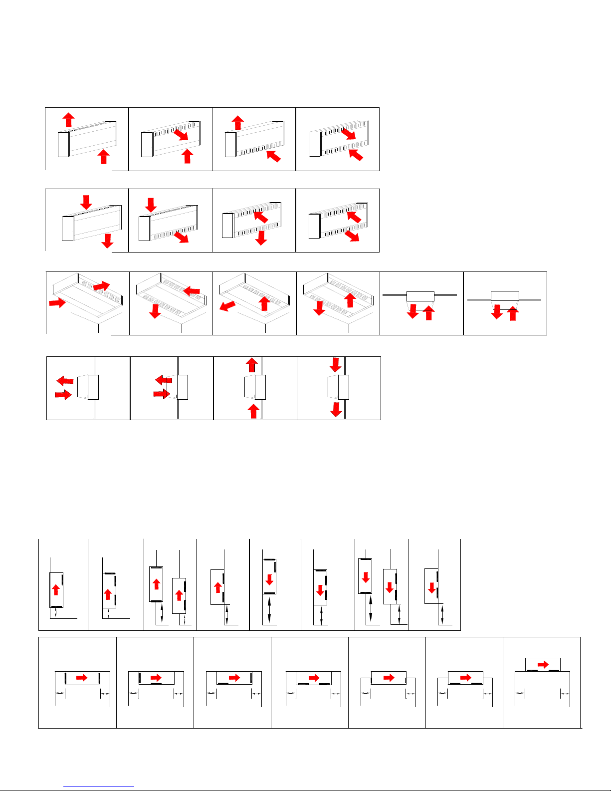
MOUNTING CONFIGURATIONS
All Angle Heater Series offers a selection of air inlet and discharge arrangements.
Inlet and outlet grille arrangements are easily altered by opening front panel of unit
Heaters Cannot be
NOTE: Semi reces sed to be recessed
MOUNTING CLEARANCES
Mounting holes are provided in the back of the cabinet, accessible through the blower
UP FLOW
DOWN FLOW
Unit may be mounted upside down to
A
B
W
C
D
Y
A
D
W
Y
D
Y
A
C
Z
B
D
X
A
Z
X
D
D
X
A
W
V
W
B
V
C
Y V
Y
V
D
W
A
V
D
Y
V
D
Y
V
A
B C D
A
B
C
D
A
B
C
D
D
D
D
D
A
A
UP FLOW
WALL
CEILING
DOWN FLOW
and removing (2) screws.
mounted on the
END!
reverse direction of air flow.
3 ½ “ maximum unless both
inlet and outlet grilles are to the
front.
SEMI RECESSED
FULLY RECESSED SEMI RECESSED SEMI RECESSED
Proper clearances are indicated for each mounting configuration. In all positions,
clearance from end of heater to a side wall is zero inches.
compartment. If necessary, remove blower deck if additional mounting screws or
bolts are desired. Blower deck may be slipped forward by loosening four screws at
the front to provide access to mounting holes.
KEY
W 6” minimum
X 12”minimum
Y 0 or greater
Z 24”minimum
V 48”minimum
Page 4
CAUTION
ll amp load
This heater must be grounded before operating, as required by the National Electric Code and by applicable local
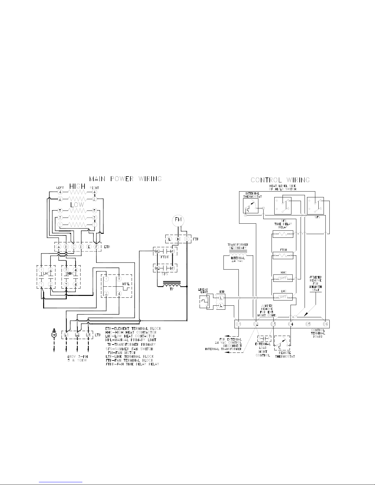
Typical Wiring
For actual wiring of your unit(s) refer to
The NEC requires that over current protection and supply wire for electric heating equipment be rated at least 125% of the fu
of the circuit. A field supplied disconnect switch should be used to control the input voltage to the unit.
All supply wiring shall conform to the latest edition of the NEC and to all local codes having jurisdiction. Conduit knockouts are
provided in the back of the wiring compartment. Make sure all field wiring connections are properly made and are tight.
Electrical Ground---
codes. Use a conductor, of the appropriate size, secured to the ground lug in the heater and to a grounded connection in the service
panel.
the diagram located inside the front
access panel.
ISSUE DATE 06/15/01 REV. DATE REV. NO. 00 EC0 NO. 1-4635 P/N 00009979 SHT. 04 OF 09
Page 5

PARTS VIEW AND PARTS LIST ..Directional Air Heater Final Assembly
Unit
Length
1
3
4
7
4
1
2
3
5
4
5 & 6
3
2
1
1
*Field adjustable for various configurations
**See page 6 for individual parts
Switch av ai lable on all units except 480V, 3-phase,
Item Part No. Description Qty
33”
46”
66”
79”
1
2
3
4
5
1
2
3
4
5
1
2
3
4
5
1
2
3
4
**
**
52293001
62273001
58337001
**
**
52293002
62273002
58337002
**
**
**
**
52293001
52293002
62273003
58337003
**
**
52293002
62273004
Heat deck assbly-SNG
Blower deck assembly-SNG
Disposable filter-SNG
Intake/discharge grille*
Front Panel
Heat deck assbly-DBL
Blower deck assembly-DBL
Disposable filter-DBL
Intake/discharge grille*
Front Panel
Heat deck assbly-SNG
Heat deck assbly-DBL
Blower deck assembly-SNG
Blower deck assembly-DBL
Disposable filter-SNG
Disposable filter-DBL
Intake/discharge grille*
Front Panel
Heat deck assbly-DBL
Blower deck assembly-DBL
Disposable filter-DBL
Intake/discharge grille*
1
1
1
2
1
1
1
1
2
1
1
1
1
1
1
1
2
1
2
2
2
2
High/Low
Thermostat
Summer Fan
(optional)
Fan Relay
2
ΠΠΠContactor
Contractor
3-wire and 600V, 3-phase and single phase units.
Required for optional summer fan in 480V, 3-
phase, 3-wire, and 600V, 3-phase and single units.
For 415/240 and 480/277 ST Option Contact
Factory for part number.
ISSUE DATE 06/15/01 REV. DATE REV. NO. 00 ECO NO. 1-4635 P/N 00009979 SHT. 05 OF 09
4” Π
Summer Fan
(optional)
Fuse/Holder
Transformer
Voltage Item
208-3/1
240-3/1
&415-3
277-1&
480-3
4-wire
480-1&
480-3
3-wire
600-3/1
All
2
1
2Π
3
1
2
3
1
2
3
1
2
3
4
5
6
7
Π Excludes 208/240V 3-phase 66” and 79” units, 18 and 24 KW.
Consult factory. See page 7 for description of control options
Control Options
B1/B8 B2/B7 B3/B5 B4/B6
51135001
58027001
60719037
51135001
58027001
60719037
51135001
58027001
60719011
51135001
58027001
60719012
51135001
58027001
60719040
42438001
Optional
Optional
51135006
58027006
N/R
51135006
58027002
N/R
51135006
58027002
N/R
51135006
58027002
N/R
51135006
58027002
N/R
42438001
Optional
Optional
51135001
58027001
N/R
51135001
58027001
N/R
51135001
58027001
N/R
51135001
58027001
N/R
51135001
58027001
N/R
42438001
Optional
Optional
B1 thru B4 – 93854088
B5 thru B8 – 93854112
51135006
58027002
41043001
51135006
58027002
41017001
51135006
58027002
41017009
51135006
58027002
41017001
51135006
58027002
58342002
42438001
44066001
40062001
Page 6

208
3/1 1 52275001
208V 1KW Heating Element
240
3/1
52275002
240V 1KW Heating Element
277
1
52275003
277V 1KW Heating Element
415
3
52275002
240V 1KW Heating Element
480/277
3/1
52275003
277V 1KW Heating Element
52275013
2,4&6KW-300V 1KW Heating Element
52275013
2&4KW-300V 1KW Heating Element
52275014
3,5&6KW-347V 1KW Heating Element
3
44067001
Manual Reset Limit
PARTS VIEW AND PARTS LIST (CONTINUED)
415
3-4wire
52289001
208/240V Motor single shaft
277
1
52289003
277V Motor single shaft
480
3-4wire
52289003
277V Motor single shaft
600
3/1
52289005
575V Motor single shaft
All
3/1
2
62441001
Blower wheel
1
208/240
3/1
52290001
208/240V Motor Double shaft
415
3-4wire
52290001
208/240V Motor Double shaft
277
1
52290003
277V Motor Double shaft
480
3-4wire
52290003
277V Motor Double shaft
600
3/1
52290005
575V Motor Double shaft
All
3/1
2
62441001
Blower wheel
2
208/240
3/1
52289001
208/240V Motor single shaft
415
3-4wire
52290001
208/240V Motor double shaft
52289003
277V Motor single shaft
52289004
480V Motor single shaft
52290004
480V Motor double shaft
52290003
277V Motor double shaft
52289005
575V Motor single shaft
52290005
575V Motor double shaft
All
3/1
2
62441001
Blower wheel
3
208/240
3/1
52290001
208/240V Motor double shaft
415
3-4wire
52290001
208/240V Motor double shaft
277
1
52290003
277V Motor double shaft
480
3-3wire/1
52290004
480V Motor double shaft
480
3-4wire
52290003
277V Motor double shaft
All
3/1
2
62441001
Blower wheel
4
1
1
3
2
Heat Deck Assembly
Blower Deck Assembly
Unit
Length
Volts Phase Item Part No. Description Qty
208/240 3/1
52289001 208/240V Motor single shaft
2
66 and 79 inch units are Custom
Specified Cabinets Unit Heaters
33”
46”
66”
79”
480 3-3wire/1 52289004 480V Motor single shaft
480 3-3wire/1 52290004 480V Motor Double shaft
277 1
480 3-3wire/1
480 3-4wire
600 3/1
600 3/1 52290005 575V Motor double shaft
1
1
52290003 277V Motor double shaft
1
52289003 277V Motor single shaft
1
1
1
1
2
NOTE: 1. 66” Units use the following sizes of Heat/Blower deck assemblies.
2. 79” Units have (2) 46” Heat/Blower deck assemblies.
Length
ΠQuantity varies with KW
ΠΠAll except for the following 66” and 79” 3-phase units: which have Qty. 2
208V – 16KW thru 24KW
240V – 20KW thru 24KW
ΠΠΠBoth 2-Wire, 3 -Wire and 4-Wire syst ems.
A) Qty.1 ea.-33
B) Qty. 1 ea.-46”
Unit
33”
46”
Volts PH. Item Part No. Description Qty
480
600
208 3/1
240 3/1 52275006 240V 2KW Heating Element
277 1 52275007 277V 2KW Heating Element
415 3 52275006 240V 2KW Heating Element
480/277 3/1 52275007 277V 2KW Heating Element
480
600 3/1 52275012 600V 2KW Heating Element
All Units
ΠΠ
ΠΠ
Π
Π
1
3
52275004 480V 1KW Heating Element
52275014 3&5KW-347V 1KW Heating Element
52275005 208V 2KW Heating Element
1
52275008 480V 2KW Heating Element
2 60149051 Linear Safety Limit 1
ISSUE DATE 06/15/01 REV. DATE REV. NO. 00 EC0 NO. 1-4635 P/N 00009979 SHT. 06 OF 09
Π
Π
1Π
Page 7

Description of control opti ons f or “Custom Specified” Cabinet Unit Heaters
Note: All units are field convertible to the following:
Load management control with an external dry switch. When closed, unit operates under control of the internal or external
ISSUE DATE 06/15/01 REV. DATE REV. NO. 00 ECO NO. 1-4635 P/N 00009979 SHT.07 OF 09
1. For control by a field supplied remote thermostat.
2.
thermostat. When open, unit turns off.
B1--- Built-in single stage thermostat and relays which are operated by a field supplied 120 volt sourc.
Night set back can be accomplished by interrupting the 120 volt source to the unit. The unit is field convertible to the
following:
1. With a program controller provided by the installer; when the controller supplies the 120 volt source to the unit, it will heat
until the internal thermostat is satisfied. At night, the program controller will switch to a zone thermostat
which will control the 120 volt source to all of the heaters.
B2--- Built-in single stage thermostat and relays which are operated by a field supplied 24 volt source.
Night set back can be accomplished by interrupting the 24 volt source to the unit. The unit is field convertible to the
following:
1. With a program controller provided by the installer; when the controller supplies the 24 volt source to the unit, it will heat
until the internal thermostat is satisfied. At night, the program controller will switch to a zone thermostat
which will control the 24 volt source to all of the heaters.
B3--- Built-in single stage thermostat and relays which are operated by and internal 24 volt source.
B4--- Built-in single stage thermostat and relays which are operated by an internal 120 volt source.
(also includes fusing in the fan circuit and the transformer primary.)
B5--- Built-in two stage thermostat and relays which are operated by and internal 24 volt source.
B6--- Built-in two stage thermostat and relays which are operated by an internal 120 volt source.
(also includes fusing in the fan circuit and the transformer primary.)
B7--- Built-in two stage thermostat and relays which are operated by a field supplied 24 volt source.
Night set back can be accomplished by interrupting the 24 volt source to the unit. The unit is field convertible to the
following:
1. With a program controller provided by the installer; when the controller supplies the 24 volt source to the unit, it will heat
until the internal thermostat is satisfied. At night, the program controller will switch to a zone thermostat
which will control the 24 volt source to all of the heaters.
B8--- Built-in two stage thermostat and relays which are operated by a field supplied 120 volt source.
Night set back can be accomplished by interrupting the 120 volt source to the unit. The unit is field convertible to the
following:
1. With a program controller provided by the installer; when the controller supplies the 120 volt source to the unit, it will heat
until the internal thermostat is satisfied. At night, the program controller will switch to a zone thermostat
which will control the 120 volt source to all of the heaters.
Note: Standard Units are equipped with B3 Control Option
Page 8

Model
Heat
STANDARD CABINET UNIT HEATER SPECIFICATIONS
Standard Unit Heaters are 33” and 46” wide.
Output
Kw
HI LO HI LO HI LO 1PH 3PH
Norm. CFM
Output
Fan Speed
RPM
BTUH
(1,000’s)
Volts/HZ
50/60
Amps
Copper Wire
Size 75°C
AWG
Maximum
Fuse Size
6333D052033B300F 5 3 250 230 1550 1400 171/10.2 208/60
6333D052433B300F 5 3 250 230 1550 1400 17.1/10.2 240/60
6333D054834B300F 5 3 250 230 1550 1400 17.1/10.2 277-480/60
6333D054833B300F 5 3 250 - 1550 - 17.1/10.2 480/60 - 7.76 14 15
6333D055733B300F 5 3 250 - 1550 - 17.1/10.2 600/60 - 5.48 14 15
6346D102033B300F 10 6 500 460 1550 1400 34.1/20.5 208/60
6346D102433B300F 10 6 500 460 1550 1400 34.1/20.5 240/60
6346D104834B300F 10 6 500 460 1550 1400 34.1/20.5 277-480/60
6346D104833B300F 10 6 500 - 1550 - 34.1/20.5 480/60 - 15.35 12 20
6346D105733B300F 10 6 500 - 1550 - 34.1/20.5 600/60 - 12.28 12 20
ΠComes factory wired as a 3-phase unit, can be field converted to single phase ΠΠcomes factory wired as 480V/3-phase/4-wire unit, can be field converted to 277V/single phase
25.04Π
21.83Π
18.95ΠΠ
49.98ΠΠ
43.57Π
37.70ΠΠ
17.57 8/10 35/25
15.38 10/12 30/20
8.02 10/14 25/15
35.06 6/8 70/45
30.68 6/8 60/40
15.87 6/12 50/20
“CUSTOM-BUILT” CABINET UNIT HEATER
MODEL NUMBER BREAKDOWN
A) Series designation –T
B) Cabi net si ze – 33 = 33 in., 46 = 46 in., 66 = 66 in., or 79 = 79 in.
C) Inlet-outl et arrangement – A , B, C, or D
D) Rating in KW – 02 through 24
E) Voltage rating – 20 = 208V, 24 = 240V, 27 = 277V, 48 = 480V, or 57 = 600V
F) Phase – 1 = 1phase or 3 = 3phase
G) Number of wires in electric service – 2 = 2wires, 3 = 3wires, or 4 = 4wires
H) Control option – B1 through B8, or ST
I) Summer Fan Switch Option – S = Switch included or 0 = No switch
J) Over current Protection Option – C = Circuit breaker included or 0 = No protection
K) Motor Fusing Option – M = Motoring fuse included or 0 = No protection
L) Filter Option – F = Filter included or 0 = No filter
M) Disconnect Switch Option – D = Switch included or 0 = No sw i tch
N) Special Paint Color Option – P = Special color or Blank = Standard
T 46 D 08 24 1 2 B3 S C M F D P
A B C D E F G H I J K L M N
ISSUE DATE 06/15/01 REV. DATE REV. NO. 00 ECO NO. 1-4635 P/N 00009979 SHT.08 OF 09
Page 9

“CUSTOM-BUILT” CABINET UNIT HEATER SPECIFICATIONS
Custom Specified Heaters are 33”, 46”, 66”, 79” wide.
# of Heat
Fan
600V 1-phase unit has (4) elements
ISSUE DATE 06/15/01 REV. DATE REV. NO. 00 ECO NO. 1-4635 P/N 00009979 SHT. 09 OF 09
Heater
Length
33”
46”
66”
79”
Π
Elements per
Deck
KW
LT RT Hi Lo Hi/Lo
2 - 2 2 1
3 - Π3 3 2
4 - 4 4 2
5 - ΠΠ5 5 3
6 - 6 6 3
4 - 2 4 2
6 - 3 6 4
8 - 4 8 4
10 - 5 10 6
12 - 6 12 6
6 2 2 6 3
Π3
9
12 4 4 12 6
ΠΠ
15
5
18 6 6 18 9
8 2 2 8 4
12 3 3 12 8
16 4 4 16 8
20 5 5 20 12
24 6 6 24 12
Heat KW
3 9 6
5 15 9
ΠΠ600V 1-phase unit has (6) elements
Speed
RPM
1550/
1400
1550/
1400
1550/
1400
1550/
1400
Total Heater Amps/Supply Wire 75 degrees C copper
Single Phase Three Phase
208V 240V 277V 480V 600V 208V 240V
10.62/14 9.33/14 8.12/14 4.67/14 3.83/14 9.22/14 8.13/14 4.80-14 4.14/14 4.40/14 3.33/14
15.42/12 13.50/12 11.73/14 6.75/14 5.50/14 9.22/14 8.13/14 5.17/14 4.14/14 4.40/14 3.38/14
20.23/10 17/67/10 15.34/12 8.84/14 7.16/14 13.40/12 11.75/14 8.34/14 5.95/14 6.21/14 6.22/14
25.04/8 21.83/10 18.95/10 10.92/14 8.00/14 17.57/10 15.38/12 8.34/14 7.76/14 8.02/14 5.48/14
29.85/8 26.00/8 22.56/10 13.00/12 10.49/14 17.57/10 15.28/12 9.34/14 7.76/14 8.02/14 6.26/14
21.13/10 18.57/10 16.00/12 9.29/14 7.46/14 18.36/10 16.16/10 9.59/14 8.11/14 9.92/14 6.49/14
30.75/8 26.90/8 23.26/10 13.45/12 10.79/14 18.36/10 16.16/10 10.23/14 8.11/14 9.92/14 6.49/14
40.36/6 35.23/8 30.48/8 17.62/10 14.12/12 26.71/8 23.42/10 16.66/10 11.73/14 12.25/12 9.39/14
49.98/6 43.57/6 37.70/6 21.79/10 17.45/10 35.06/8 30.68/8 16.66/10 15.35/12 15.87/12 12.28/12
59.59/4 51.90/6 44.92/6 25.95/8 20.78/10 35.06/8 30.68/8 18.56/10 15.35/12 15.87/12 12.28/12
31.75/8 27.90/8 24.12/8 13.95/12 11.29/14 27.58/8 24.29/8 - 12.25/12 14.32/12 9.82/14
46.17/6 40.40/8 34.99/8 20.20/10 16.29/12 27.58/8 24.29/8 - 12.25/12 14.32/12 8.87/14
60.59/4 52.90/4 45.82/6 26.45/8 21.28/10 40.11/6 35.17/8 - 17.68/10 18.46/10 15.61/12
75.02/3 65.40/4 56.65/4 32.70/8 25.45/8 52.63/4 46.06/6 - 23.11/10 23.89/10 15.66/12
89.44/2 77.90/3 67.48/4 38.95/6 31.27/8 52.63/4 46.06/6 - 23.11/10 23.89/10 18.54/10
42.26/6 37.14/6 32.00/8 18.57/10 14.92/12 36/72/6 32.32/8 - 16.22/10 19.84/10 12.98/12
61.50/4 53.80/4 46.52/6 26.90/8 21.58/10 36/72/6 32.32/8 - 16.22/10 19.84/10 12.98/12
80.72/2 70.46/3 60.96/4 32.23/8 28.24/8 53.42/4 46.84/6 - 23.46/10 24.50/8 18.78/10
NA 87.14/2 75.40/3 43.57/6 34.90/8 70.12/3 61.36/4 - 30.70/8 31.74/8 24.56/8
NA NA 89.84/2 51.90/6 41.56/6 70.12/3 61.36/4 - 30.70/8 31.74/8 24.56/8
415V
4-Wire
480V
3-Wire
480V
4-Wire
600V
Page 10

)
TERSTERS
TERSTERS
TERS
ABINET UNIT HEAABINET UNIT HEA
ABINET UNIT HEAABINET UNIT HEA
ABINET UNIT HEA
Field Supplied
P/N: 9966
ter.ter.
ter.ter.
ter.
y, they arey, they are
y, they arey, they are
y, they are
tive use onltive use onl
tive use onltive use onl
tive use onl
aa
aa
a
INSTALLATION INSTRUCTIONS
AMES FOR CAMES FOR C
AMES FOR CAMES FOR C
AMES FOR C
TRIM FRTRIM FR
TRIM FRTRIM FR
TRIM FR
maximum, unless both inlet and outlet with screws or rivets
NOTE: Semi-recessed to be recessed 3-1/2” Attach Trim Frame to Cabinet
grilles are to the front. (
NOTE:
ames are for decorames are for decor
ames are for decorames are for decor
ames are for decor
trim fr trim fr
trim fr trim fr
trim fr
caution:caution:
caution:caution:
caution:
Semi-recessed Fully recessed front view
Side View Side View
* Trim Frame extends 1” beyond outer dimensions of heater.
made for supporting the cabinet unit hea made for supporting the cabinet unit hea
made for supporting the cabinet unit hea made for supporting the cabinet unit hea
made for supporting the cabinet unit hea
notnot
notnot
not
Page 11

HEATING PRODUCTS WARRANTY COVERAGE
Heating Products Elements in Baseboard s
Thermostats and Controls
10 Years
2 Years
VENTILATION PRODUCTS WARRANTY COVERAGE
All other Ventilation Products
1 Year
LIMITED WARRANTY
Products manufactured by TPI Corporation are warranted to the original consumer to be free from defects in material and
workmanship for twelve (12) months from the original purchase date.
The TPI limited warranty does not cover products that have been modified outside of our factory, damage or failure caused by acts
of God, abuse, misuse, connected to or placed on other than rated voltage, abnormal usage, fault, installation, failure to follow
suggested maintenance procedures enclosed with the product, improper maintenance or any repairs other than those provided by
an authorized TPI service center.
There are no obligations or liabilities on the part of the Corporation for consequential damages arising out of or in
connection with the use or performance of the product or other indirect damages with respect to loss of property,
revenues, profit, costs of removal installation, or reinstallation.
All implied warranties with respect to TPI products, including implied warranties for merchantability and implied
warranties for fitness, are limited in duration to twelve (12) months from original date of purchase, except those products
or parts of products which are warranted for long periods thereon.
Some states do not allow the exclusions or limitation of incidental or consequential damages and some states do not allow
limitations on how long an implied warranty lasts. The above exclusions or limitations may not apply to you.
During the warranty period, TPI Corporation will, at its sole option, repair or replace any defective parts or products returned, freight
prepaid, to the TPI Corporation factory or such other locations as TPI Corporation may designate. Returned products must be
packaged carefully and TPI Corporation shall not be responsible for damage in transit.
When ret urning parts, the owner must provide the model number of the product and nature of difficulty being experienced. This
warranty does not obligate TPI Corporation to bear the cost of labor in replacing any assembly, unit or component part thereof, nor
does the company assume any liability for secondary charges, expenses for installing or removal, freight or damages. There will
be charges rendered for product repairs made after the warranty period has expired. Proof of purchase, including date, must
accompany request for in-warranty service. In any event, TPI Corporation’s maximum liability shall not in any case exceed the list
price for the product claimed to be defective. This warranty gives to you specific legal rights and you may have other rights, which
may vary from state to state. For the name of your nearest authorized TPI Corporation service center, please write to TPI
Corporation, P.O. Box 4973, Johnson City, TN 37602.
All other Heating Products
Series HD or HDH Fans
Series UHP or IHP Fans
1 Year
5 Years
3 Years
 Loading...