

Page 1
RFKit-5 Installation & Operation Instructions:
General:
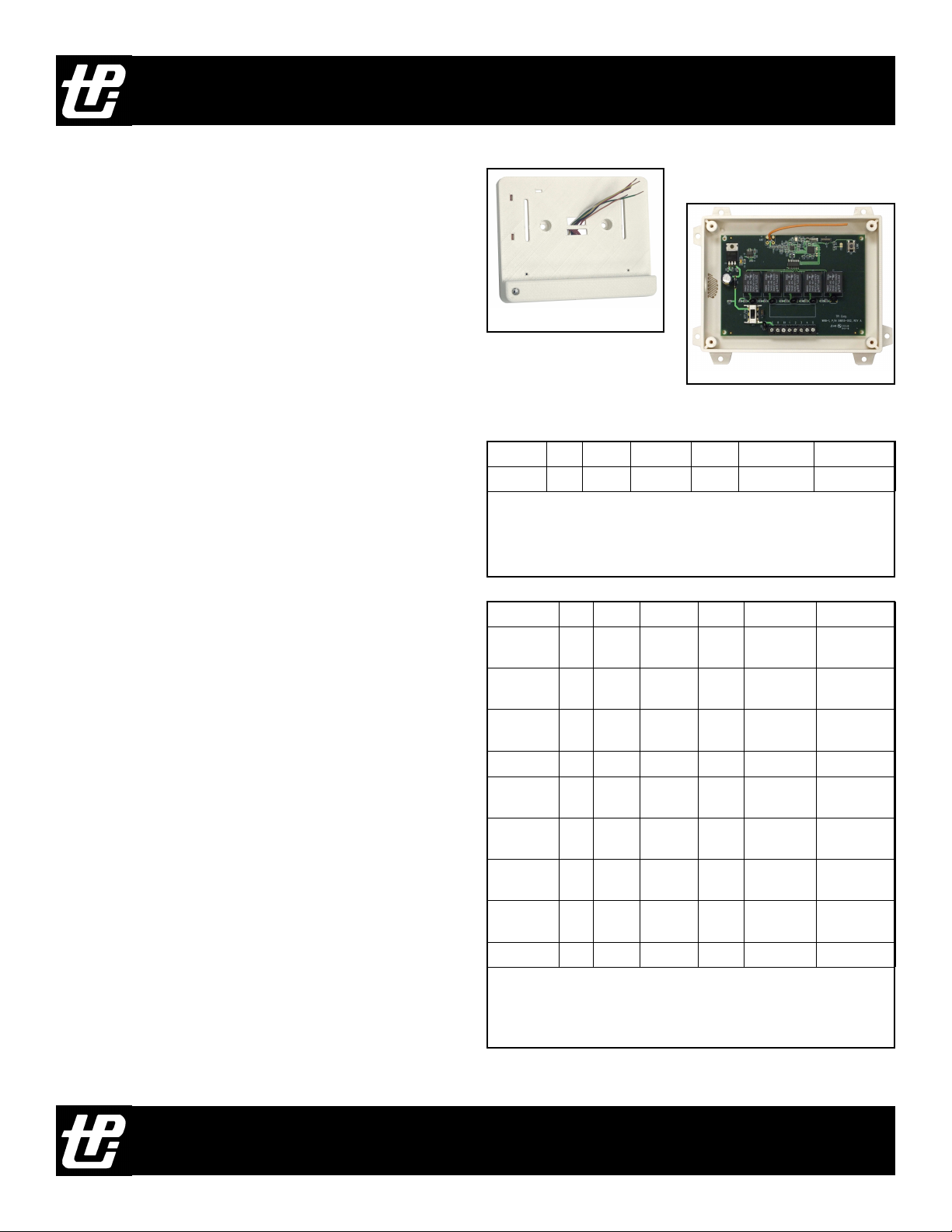
The RFKit-5 is comprised of two pieces, the RFT-1,
thermostat interface, and the RFR-5 relay package.
Utilizing the RFKit-5 allows standard low voltage
thermostats to be used wirelessly to control your HVAC
system.
The RFKit-5 has been designed to interface with many
types of heating and cooling equipment, including Heat
Only, Cool Only, Heat/Cool, Heat Pump, and Multistage
Heat and/or Cool. This is accomplished by incorporating
5 relays that can be used for whatever operation that is
required by the system and the thermostat.
The RFT-1 Thermostat Interface incorporates a
common wire and 5 inputs. Although color coded for a
standard 4 wire Heat/Cool thermostat with two additional
inputs, the actual operation of each input is determined by
its connection to the thermostat. The input wires of the
RFT-1 correspond directly to the outputs of the RFR-5.
The chart to the right illustrates the wire color of the RFT1 to the corresponding terminals of the RFR-5.
RFT-1 Installation
Mount the RFT-1 to the wall using the two mounting
holes on each side of the wires. Use optional (included)
stand legs if the RFT-1 is to be used on a table or desk.
The RFT-1 should be placed about 5 feet above the floor
in an area that will represent ambient temperature.
Placement should avoid heat or cool sources such as
lamps, windows, and appliances.
Run the wires from the RFT-1 through the wire hole(s)
in the thermostat. Attach thermostat to RFT-1 using
screws (included). Use caution not to over tighten screws.
Connect the wires to the appropriate terminals using the
wiring chart shown to the right. It is critical for the inputs
to the RFT-1 match the outputs of the RFR-5 RF Relay
System Interface.
RFT-1
RFR-5
RFT-1 Red White Yellow Green Red/White Blue/White
RFR-5 R1 1 2 3 4 5
Connections to the thermostat must match the outputs of the
RFR-5. If the white wire of the RFT-1 is connected to W on the
thermostat, then W from the system must be connected to
terminal 1 on the RFR-5 relay interface.
RFT-1 Red White Yellow Green Red/White Blue/White
2 Wire
Heating
3 Wire
Cooling
4 Wire
Heat/Cool
Heat Pump R W2 Y1 G B or O E
2-4 Stage
Heating
2-4 Stage
Cooling
2 Stg Heat
2 Stg Cool
3 Wire
Zone
HotPod R W N/C G W2 N/C
By connecting the RFT-1 Thermostat Interface to the
thermostat using these connections, and applying the associated
label to the RFR-5 Relay Interface, wiring will match system
connections.
R W N/C N/C N/C N/C
R N/C Y G N/C N/C
R W Y G N/C N/C
R W1 W2 G W3 W4
R Y4 Y1 G Y2 Y3
R W1 Y G W2 Y2
R W Y N/C N/C N/C
TPI Corporation - PO Box 4973, Johnson City, TN
Tel: 423-477-4131 Fax: 423-477-0084 Web: TPICORP.COM
Page 1
Page 2
RFKit-5 Installation & Operation Instructions:
RFR-5 Installation:
Mount the RFR-5 in a convenient location near the HVAC
system. The RFR-5 incorporates an antenna that is used to
transmit and receive signals from the RFT-1. The RFR-5 must
be located with minimal interference of the radio signals
between it and the RFT-1. Avoid metal as much as possible.
Before attaching any wires to the RFR-5, turn off power to
the system.
The RFR-5 requires a 24VAC source of power to operate. If
both R & C terminals are accessible from the system
transformer these should be connected to the R and C terminals
on the RFR-5. The J11 jumper is left in place. R1 will not have
a wire connected to it. NOTE: The R terminal from the system
must be connected to the R terminal of the RFR-5. The C
terminal of the system must be connected to the C terminal of
the RFR-5. If these are reversed the system will not work.
If both the R and C terminals of the HVAC system are not
accessible, a separate 24 volt transformer must be used. If a
separate 24VAC transformer is used, connect wires to the R &
C terminals, and remove the J11 jumper. The R wire from the
system will be connected to R1 on the RFR-5.
Use the chart to the right to connect remaining wires from
system. NOTE: Connections to the RFR-5 must match the
RFT-1 connections to the thermostat. Please note that we have
included several terminal designator labels for the most
common applications to be applied to the RFR-5 circuit board
to help simplify installation. Apply the label to the RFR-5
circuit that matches your system.
RFR-5
Harness
Colors
2 Wire
Heating
3 Wire
Cooling
4 Wire
Heat/Cool
Heat Pump C R R1 W2 Y1 G B/O E
2-4 Stage
Heating
2-4 Stage
Cooling
2 Stg Heat
2 Stg Cool
3 Wire Zone C R R1 W Y
HotPod C R W1 Y/G W2
The RFR-5 comes pre-wired with a wiring cable. If longer
cable is needed, remove the installed cable.
By connecting the RFT-1 Thermostat Interface to the
thermostat using these connections, and applying the
associated label to the RFR-5 Relay Interface, wiring will
match system connections.
Note: There is no wire connected to R1 of the RFR-5. If a
separate transformer is used, connect Blue and Red wires to
the separate transformer. Run an additional wire to connect
system power (R) to R1. Remove J11 jumper.
C R R1 1 2 3 4 5
Blue Red White Yellow Green Black Brown
C R R1 W
C R R1 Y G
C R R1 W Y G
C R R1 W1 W2 G W3 W4
C R R1 Y4 Y1 G Y2 Y3
C R R1 W1 Y1 G W2 Y2
Note: This equipment has been tested and found to comply with
the limits for a Class B digital device, pursuant to part 15 of the
FCC Rules. These limits are designed to provide reasonable
protection against harmful interference in a residential
installation. This equipment generates, uses and can radiate
radio frequency energy and, if not installed and used in
accordance with the instructions, may cause harmful
interference to radio communications. However, there is no
guarantee that interference will not occur in a particular
installation. If this equipment does cause harmful interference
to radio or television reception, which can be determined by
turning the equipment off and on, the user is encouraged to try
to correct the interference by one or more of the following
measures:
—Reorient or relocate the receiving antenna.
—Increase the separation between the equipment and receiver.
—Connect the equipment into an outlet on a circuit different
from that to which the receiver is connected.
—Consult the dealer or an experienced radio/TV technician for
help.
TPI Corporation - PO Box 4973, Johnson City, TN
Tel: 423-477-4131 Fax: 423-477-0084 Web: TPICORP.COM
Page 2
Information to user.
Changes or modifications not expressly approved by the party
responsible for compliance could void the user's authority to
operate the equipment.
This device complies with Industry Canada’s licenceexempt RSSs. Operation is subject to the following
two conditions:
(1) This device may not cause interference; and
(2) This device must accept any interference,
including interference that may cause undesired
operation of the device.
Page 3

RFKit-5 Installation & Operation Instructions:
Operation:
Power up:
Install batteries in the RFT-1. When batteries are first installed in
the RFT-1 the LED will stay on for 1 second, and then blink 3
times. When power is applied to the RFR-5 The LED will stay on
for 1 second and blink 3 times.
LED Indicators:
Both the RFT-1 and the RFR-5 have LED indicators. The
RFT-1 uses the LED to indicate loss of communication, low
battery, and pairing mode. The RFR-5 LED indicates when there
has been a loss of communication and is also used for pairing.
RFT-1 LED Indicators:
Loss of communication: LED blinks twice every 5 seconds. Note:
Anytime there is a power outage there will be a loss of
communication between the RFT-1 and the RFR-5. Once power
is restored, communication between the RFT-1 and RFR-5 will
automatically be restored.
Low Battery:
The 2 AAA batteries will typically last between 2 and 3 years.
When the battery voltage reaches a low level the LED will blink
4 times every 5 seconds. Once the low battery LED is activated
you will have up to 30 days to replace the batteries before the
RFT-1 will stop functioning.
Pairing:
The RFT-1 and the RFR-5 are sold as a set that has already
been paired at the factory. Once paired to each other, pairing will
not be required again. If however, either the RFT-1 or the RFR-5
is replaced, the new unit will need to be paired to the other unit.
To pair the RFT-1 to the RFR-5:
1. Apply 24VAC to the R and C terminals of the RFR-5.
2. Install 2 AAA batteries into the RFT-1.
3. Press and hold the “Link” button on the RFR-5 for two
seconds. The LED will turn on and stay on.
4. Press and hold the “Link” button on the RFT-1 for two
seconds. The LED will stay on until it communicates to
the RFT-5.
5. If pairing is successful, the LED will blink 5 times
followed by the LED turning off and staying off.
NOTE: If the pairing is not successful, the LED will blink twice
every 5 seconds, indicating loss of communication. If this
happens, move the units closer together and repeats steps 1-5.
If the units are not within range or there are obstructions
between the RFT-1 and the RFR-5, they may need to be moved
closer together to pair. Metal between the two units will block the
radio signal.
Install Batteries as shown LED LINK Button
RFT-1 Battery Compartment with LED and Link Button
LINK Button LED
RFR-5 LED and Link Button
FCC ID: ZIN-58815001
IC : 9673A-58815001
This device complies with part 15 of the FCC
Rules. Operation is subject to the following two
conditions: (1) This device may not cause
harmful interference, and (2) this device must
accept any interference received, including
interference that may cause undesired operation.
FCC ID: ZIN-58815002
IC : 9673A-58815002
This device complies with part 15 of the FCC
Rules. Operation is subject to the following two
conditions: (1) This device may not cause
harmful interference, and (2) this device must
accept any interference received, including
interference that may cause undesired operation.
Model RFT-1
Model RFR-5
TPI Corporation - PO Box 4973, Johnson City, TN
Tel: 423-477-4131 Fax: 423-477-0084 Web: TPICORP.COM
Page 3
Page 4

RFKit-5 Installation & Operation Instructions:
HotPod Instructions:
The RFKit-5 comes with everything you need to
connect the RFT-1 to the UT8003 HotPod thermostat, as
well as the cable used to connect the RFR-5 to the HotPod
unit.
Connecting the RFT-1 to the UT8003
Thermostat:
Determine where the RFT-1 is to be mounted. Attach to
the wall with the included screws and wall anchors, or use
the included pieces for freestanding. There are six wires
coming out of the RFT-1. The only wires needed to
connect to the UT8003 are the Red, White, Green, and
Red/White striped wire. Cut the remaining two (Yellow
and White/Blue) as short as possible, so they won’t be in
the way.
Run the wires through the holes as shown, and attach
the UT8003 to the RFT-1. Cut off excess wire, strip 1/4”
and connect to terminals as shown.
Connecting the RFR-5 to the HotPod
Use the included cable to connect the RFR-5 to the
HotPod Harness connector. The cable includes extra
wires. Use the terminal label for the HotPod to help
simplify installation. Use the chart to the right to wire the
cable to the proper RFR-5 terminals.
The other end of the cable will be connected to the
HotPod Harness. Connector is two pieces that simply pull
apart. Pull the two pieces apart and insert wires from the
RFR-5 into the connector as shown. Strip wires about
1/4”, and insert the wires into the connector as shown.
Red must go into terminal 1.
White must go into terminal 2.
Black must go into terminal 3.
Green must go to terminal 4.
Blue must go into terminal 5.
Make sure each wire has been inserted securely by
pulling on each one separately to see if it holds.
Reconnect to other half of the connector.
Follow instructions on Page 3 for operation of the
RFKit-5.
Mount the RFT-1 Thermostat Interface to the wall,
or use the included desk stand attachments.
Mounting Holes
Run the wires through the three holes in the board
and attach to the appropriate terminals.
White to W.
Green to G.
Red to R.
Red/White
to W2.
HotPod Wiring Chart
RFR-5 C R R1 1 2 3 4 5
Cable Blue Red N/C White N/C Green Black
HotPod C R W1 Y/G W2
Harness 5 1 2 4 3
TPI Corporation - PO Box 4973, Johnson City, TN
Tel: 423-477-4131 Fax: 423-477-0084 Web: TPICORP.COM
Page 4
 Loading...