

Page 1
505L
LASER PHOTO /
CONTACT
TACHOMETER
Instruction Manual
Page 2
WARNING
Read instructions before operating:
Be sure these instructions accompany the tool
when passed from one user to a new or inexperienced user.
Rotating equipment can cause flying particles
Wear Safety Goggles (User and bystanders).
Flying particles can cause eye injury.
Keep yourself, clothing and test equipment
clear of moving parts.
Note: To zero previous readings on all tach
operations, Press and hold the START
button then press the desired function
button. If a stored value appears,
release START button until the display
goes off. Then press the START button
immediately and a zero reading will be
displayed until the unit is used for measuring RPM or the START button is
released.
2
CAUTION: LASER RADIATION - DO NOT STARE INTO
BEAM. OUTPUT <1mW WAVELENGTH 635
- 670nm. CLASS II LASER PRODUCT
Page 3
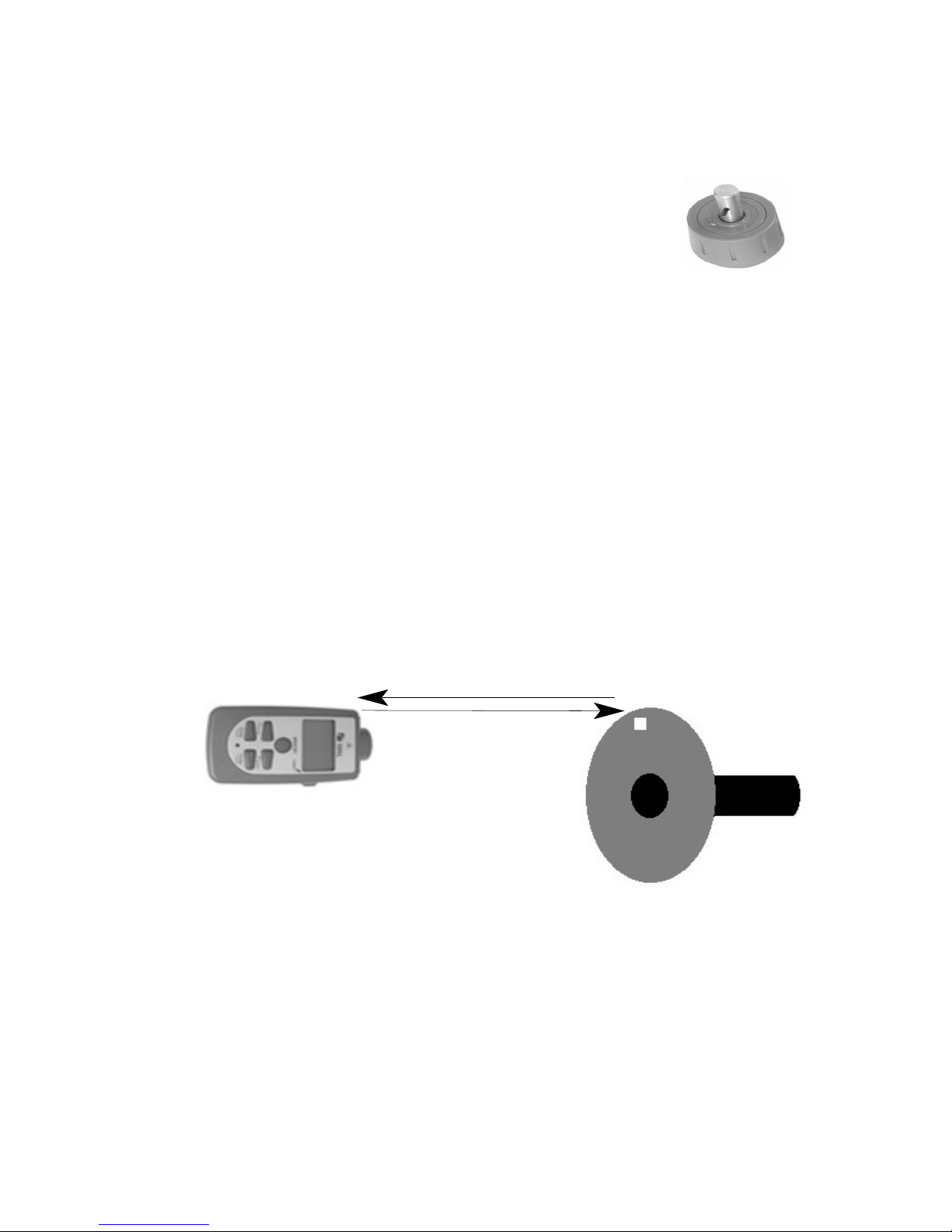
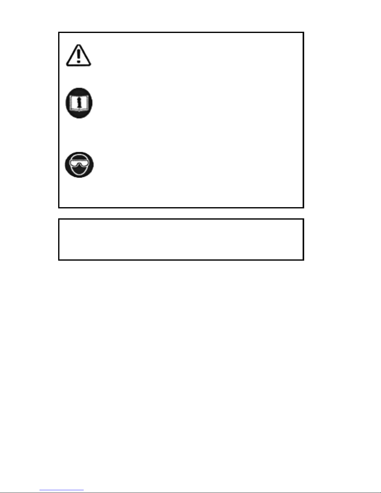
PHOTO TACH OPERATION
Contact collar
25’ maximum
distance.
Measurement Procedure:
1. Unscrew contact collar from optical end of
505L (if attached).
2. Attach a piece of reflectIive tape on the rotating object to
be measured.
3. Depress and hold the START button and then press the
Photo button (lower right) on the 505L.
4. With the start button depressed, point the optical end at
the rotating surface so the relective tape passes the
laser every rotation.
Note: The 505L can be set to continuous on, eliminating
the need to hold the START button down. Press and hold
the START button then press the MEMORY button. “L-on”
will display indicating continuous on is activated. Deactivate
continuous on by holding down the START button and press the
MEMORY button. “L-off” will display indicating continuous on is
deactivated.
5. Read the RPM on the LCD display.
Maximum distance to target is dependent on several items like
the strengh of reflection of the laser, ambient light conditions,
and the surface of the item under test. For best results the
background surface should be dark as compared to the reflective tape. If readings are unstable, move closer to the target for
better performance. At long distances a tripod or other rest
may be necessary for proper function.
3
Page 4
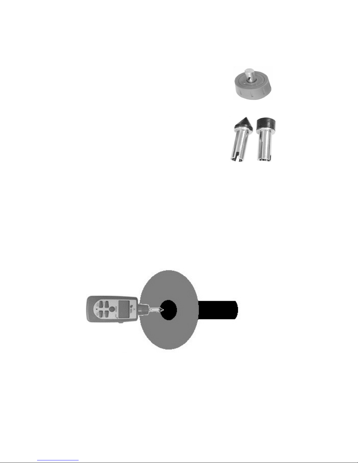
CONTACT TACH OPERATION
Contact collar
Cone
Tip
Concave
Tip
Measurement Procedure:
1. Screw the contact collar onto the optical
end of the 505L.
2. Attach the cone or concave tip to end of
the contact collar shaft.
3. Press and hold the START button and
then press the Contact button (lower left)
on the 505L.
4. While pressing the START button, hold the
wheel against the center end of the rotating shaft.
Note: The 505L can be set to continuous on, eliminating the need to hold
the START button down. Press and hold the START
button then press the MEMORY button. “L-on” will dis-
play indicating continuous on is activated. Deactivate continuous on by holding down the START button and press the
MEMORY button. “L-off” will display indicating continuous
on is deactivated.
5. Read the RPM on the LCD.
Lightly press the cone or concave tip to the center of
the rotating shaft. Measuring from anywhere but the
center will result in incorrect readings.
4
Page 5

SURFACE SPEED OPERATION
Measurement Procedure:
1. Screw the contact collar onto the optical
end of the 505L.
2. Attach the surface speed wheel to the
end of the contact collar shaft.
3. Press and hold the START button and then
press the ft/min (feet per minute) or m/min
(meters per minute) on the 505L.
4. While pressing the START button, hold the
wheel against the moving surface.
Note: The 505L can be set to continuous on, eliminating the need to hold the
START button down. Press and hold the START button then press the MEMORY but
ton. “L-on” will display
indicating continuous on is activated. Deactivate continuous
on by holding down the START button and press the MEMORY button. “L-off” will display indicating continuous on is
deactivated.
5. Read the speed on the LCD.
Note: In this mode the meter displays the surface
speed in ft/min (feet per minute) or m/min (meters per
minute) and not RPM. Do not use the surface speed
wheel to measure RPM. Displayed readings will be
incorrect.
5
Contact collar
Surface
Speed Wheel
Touch the surface
speed wheel to
the item under
test.
Page 6

MEMORY RECALL OPERATION
Note: The memory resets itself once the
START button is depressed and stable measurements are displayed for 10 seconds or
12 revolutions (whichever is longer). The
values are stored when the START button is
released.
1. When you are finished taking measurements,
release the START button.
2. Depress the MEMORY button once, the
LAST reading will be displayed
3. Press the MEMORY button twice, the MAX
reading will be displayed.
4. Press the MEMORY button three times, the
MIN reading will be displayed.
Unit will power off after 5 seconds.
CONTINUOUS ON OPERATION
The 505L can be set to continuous on,
eliminating the need to hold the START
button down.
1 Press and hold the START button then
press the MEMORY button. “L-on” will display indicating continuous on is activated.
2. Deactivate continuous on by holding down
the START button and press the MEMORY button. “L-off” will display indicating
continuous on is deactivated.
6
Page 7

BATTERY REPLACEMENT
Measurement Procedure:
1. Remove the screw holding the battery compartment cover in place on the back of the 505L.
2. Slide the cover off of the unit.
3. Remove the 2 each “AA” alkaline batteries and
replace with the same type.
4. Replace the cover and screw.
STANDARD ACCESSORIES
Reflective Tape . . . . . . . . . . . . . . . . . . . . . . .A501
Contact RPM Adapter (screw on) . . . . . . . . .A502
RPM Adapter (Cone Type) . . . . . . . . . . . . . .A503
RPM Adapter (Funnel Type) . . . . . . . . . . . . .A504
Surface Speed Test Wheel . . . . . . . . . . . . . .A505
(O.D. 48.7 mm exactly)
Carrying case . . . . . . . . . . . . . . . . . . . . . . . .A908
7
Page 8

OPERATION SPECIFICATIONS
Function Range Accuracy
Photo Tach: 6 - 30,000 RPM ± 0.1% of FS + 1 digit
Contact Tach: 6 - 20,000 RPM ± 0.1% of FS + 1 digit
Surface Speed: 0.9 - 3,046 m/min ± 0.1% of FS + 1 digit
2.0 - 9,990 ft/min ± 0.1% of FS + 1 digit
GENERAL SPECIFICATIONS
Display: 5 Digit LCD
Operating Temperature: 32°to 122°F (0°to 50°C)
Operating Humidity: 80% Max. R.H.
Power Supply: AA Alkaline Bat. (2)
Maximum Distance from Target (photo mode): 25 feet**
Detection Type: Laser reflection
Laser Output: Class II 635~670nm
Signal Output: +5V pulsed
Tripod Connection: 1/4 inch
** Max distance to target is dependent on several items like
the strengh of reflection of the laser, ambient light condi-
tions, and the surface of the item under test. For best results
the background surface should be dark as compared to the
reflective tape. If readings are unstable, move closer to the
target for better performance.
8
Page 9

Output Signal (+5V Pulsed)
1 : +5V Pulse Out
2 : N.C.
3 : GND
The 505L incorporates a +5V pulsed output to trigger external devices:
Connect a lead to the pulsed
output jack (see below).
Output pulses +5V with each
reflected signal from the
device under test.
Wiring Diagram for Pulsed Output Lead
+5V Pulsed Output
9
Page 10

Tripod Connection
505L Tripod
mount.
Standard 1/4”
threaded
mount accepts
various
tripods and
adapters.
The 505L is equipped with a tripod connection. This
connection is located on the back of the instrument
and can be used for added stability when taking
measurements at long distances.
Page 11

Notes:
Page 12

The Value Leader
TM
www.tpi-thevalueleader.com
Test Products International, Inc.
9615 SW Allen Blvd
Beaverton, OR 97005-4814 USA
Ph: 503-520-9197 Fax: 503-520-1225
Test Product International Ltd.
342 Bronte Street South, Unit 9
Milton, Ontario L9T 5B7
Ph: 905-693-8558 Fax: 905-693-0888
Test Products International UK Ltd.
Longley House, East Park
Crawley, West Sussex RH10 6AP
Ph: +44 (0) 1293 561212 Fax: +44 (0) 1293 813465
505L Instruction Manual
copyright © 2014, Test Products International, Inc
 Loading...