

Page 1
3420/AFC SERIES
INSTALLATION
Recessed Mounting
3420/AFC Series
ATTENTION: Read carefully before
attempting to install, operate or
service the heater.
INSTRUCTIONS
1
14
" (362 mm)
4
3
"
8
19
(492.1 mm)
INSTALLATION INSTRUCTIONS:
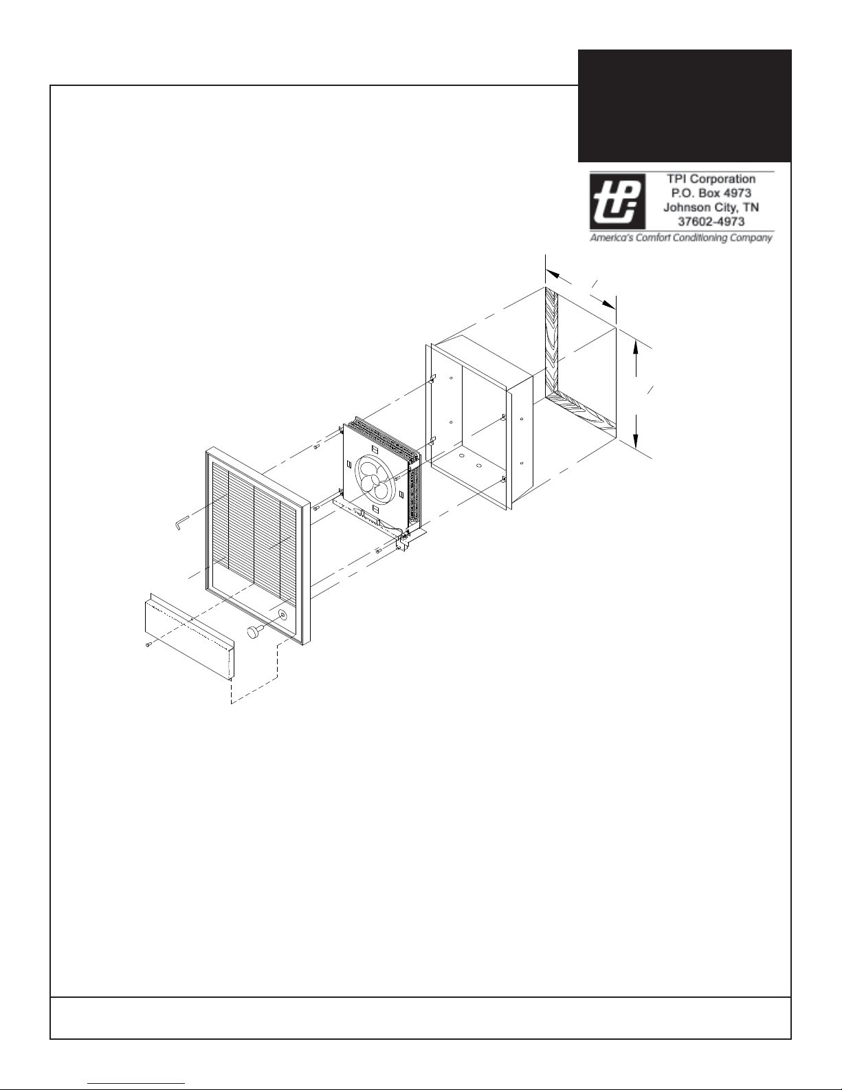
1. Heater box 3420/AFC is installed just like ordinary
outlet box. Box should be mounted in the wall - top
side up, so that the front edges are 3/16” away from
the finished wall surface.
2. The knockouts on bottom and back of box can be
GENERAL SAFETY INFORMATION / CAUTION:
• Mount in vertical position only.
• Do not install any closer than 12” to any vertical
surface or 12” to floor.
• Do not mount beneath towel racks or behind doors.
• Heater must have no obstructions in front of it.
• Make certain power supply is same as nameplate
voltage on heater.
used for conduit, metallic or nonmetallic armored
cable. Terminate feed lines at knockout.
3. Mount heater mechanism to interior of box by
inserting straight into box engaging (4) lower tabs on
interior mounting brackets with (4) tabs on wall box.
Secure with (4) screws supplied.
4. Mount heater front to heater mechanism mounting
brackets (4) top tabs with (4) allen head screws trapped
behind louvers to engage (4) allen head screws.
• All wiring must conform to the National Electric Code
and existing local code requirements.
Thermal Cutout operation shown on reverse page.
Form 9282
REV. 2/06
IMPORTANT: OWNER SHOULD RETAIN THESE INSTRUCTIONS FOR FUTURE REFERENCE
Page 2
3420/AFC SERIES
INSTALLATION
Surface Mounting
Semi-Recessed Mounting
3420/AFC Series
ATTENTION: Read carefully
before attempting to install,
operate or service the heater.
INSTRUCTIONS
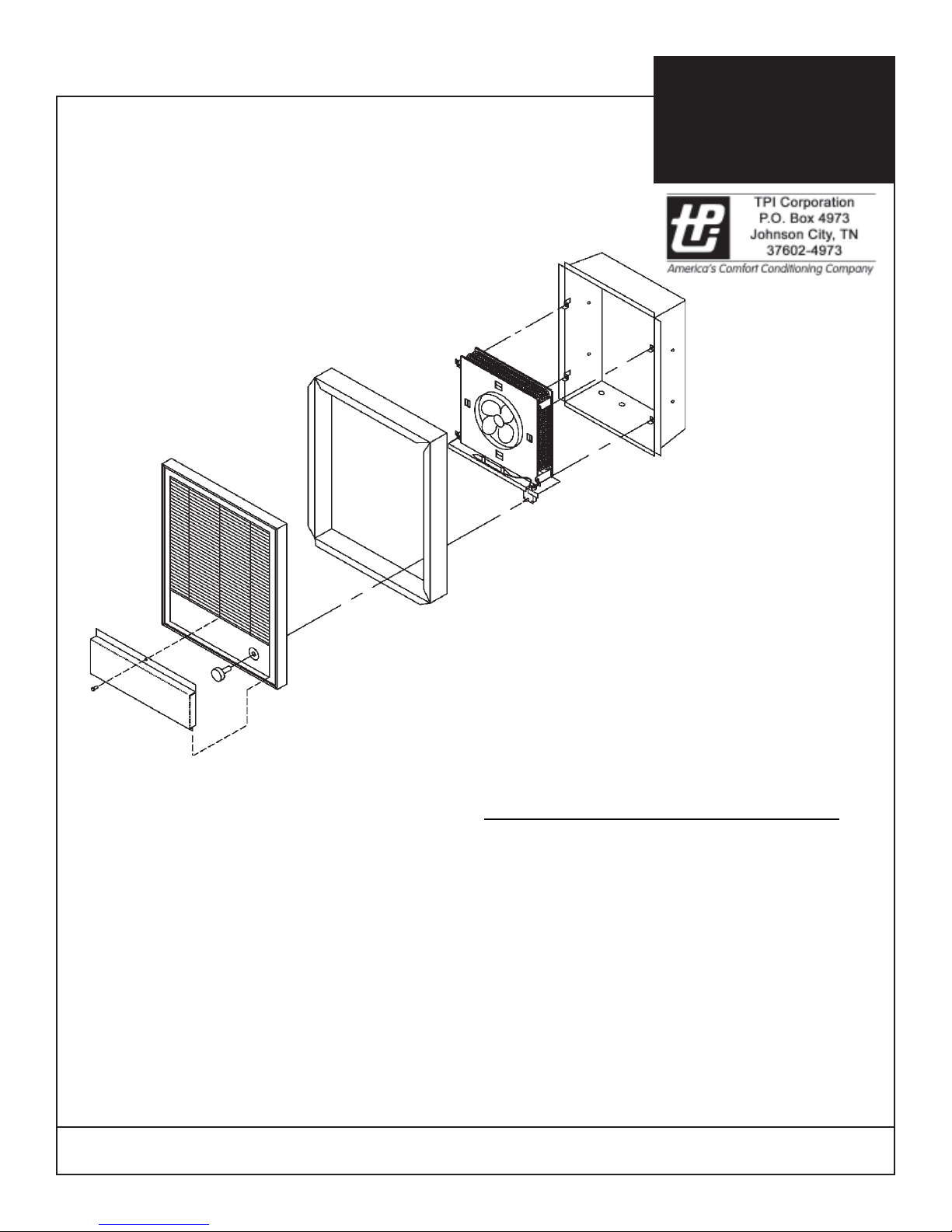
1. For surface mounting attach 3420/AFC box to wall.
For semi-recessed mounting 3420AFC box should be
set in the wall so the flange is out from the finished
wall a distance equal to the frame depth (1” for a 1”
frame, 2” for a 2” frame).
GENERAL SAFETY INFORMA TION / CAUTION:
• Mount in vertical position only.
• Do not install any closer than 12” to any vertical
surface or 12” to floor.
• Do not mount beneath towel racks or behind doors.
• Heater must have no obstructions in front of it.
• Make certain power supply is same as nameplate
voltage on heater.
• All wiring must conform to the National Electric
Code and existing local code requirements.
INSTALLA TION INSTRUCTIONS:
• For Surface Mounting use extener 3420/AFC EX34
• For Semi-Recessed Mounting use extender 3420/
AFC EX16 for 2”, or 3420/AFC EX8 for 1”
• Box 3420/AFC must be used in conjunciton with
accessory extender.
2. Remove knockout(s) in 3420/AFC as required.
3. Proceed as with recessed installation described on
front - steps 2 & 3.
4. Extender frame is attached to heater front (slip fit)
and this assembly is then attached to the heater
following step 4 on front. Frame is captured between
heater front and finished wall.
THERMAL CUTOUT OPERA TION
(ZERO-VOL T) LIMIT CONTROL
T o reset thermal cutout disconnect all power for 5 minutes
than energize unit. If fault continues disconnect power and
check for cause.
(CAPILLARY) LIMIT CONTROL
T o reset thermal cutout disconnect all power , when heater
has cooled locate the two 1/4” dia. holes in the control
panel portion of the front grille. Using a small screwdriver or
pencil press the reset button (with minimal amount of force)
through the 1/4” dia. opening, then restore power to the
unit. If fault continues disconnect power and check for
cause.
Form 9282
IMPORTANT: OWNER SHOULD RETAIN THESE INSTRUCTIONS FOR FUTURE REFERENCE
 Loading...