

Page 1
BASEBO ARD HEATER
Commercial / Residential
2900/D SERIES
A TTENTION: Read carefully before
attempting to install, operate or service
the Baseboard Heater. Retain these
instructions for future reference.
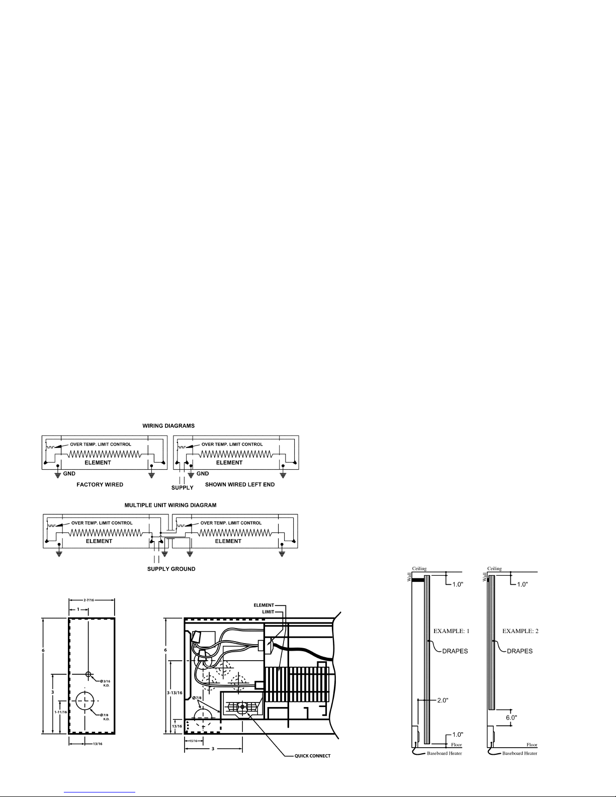
RECOMMENDATIONS FOR DRAPE PLACEMENT
NEAR BASEBOARD HEATER
1. Allow minimum clearance of 1” from drapes to
ceiling and to top of floor covering to permit air
LOCATION OF HEATER
Heaters should be located to provide a blanket of heat
over the coldest wall of the room, preferably on a outside
wall under a window.
circulation (example 1, figure 2.)
2. Hang full length drapes to provide a minimum of 2”
airspace between heater front and nearest drape fold
as shown in example 1, figure 2.
INSTALLATION
INSTRUCTIONS
CAUTIONS AND WARNING STATEMENTS
1. Wiring procedures and connections should be in
accordance with national and local codes having
jurisdiction. Note: all baseboards must be grounded
in accordance with article 250 of the N.E.C.
2. Do not install baseboard heater below electrical
convenience receptacles (outlets).
3. Do not install insulation on any inside surface of this
baseboard heater. The over temperature control
may be rendered inoperable resulting in possible
hazard in the event of abnormal operation or
blockage.
4. High temperatures are present at outlet air
openings. Keep electrical cords, drapes and other
furnishings or objects clear of these openings.
5. To reduce risk of fire, do not store or use gasoline or
other flammable vapors and liquids in the vicinity of
the heater.
6. High temperatures, keep electrical cords, drapes
and other furnishings away from the heater.
3. Hang short drapes to provide minimum of 6” clear
ance between bottom of drapes and top of heater,
preferably more (example 2, figure 2).
4. Do not under any condition allow drapery to come in
contact with heater . Some fabrics discolor in time
from exposure to sunlight or warm air. Check to make
sure drapery material will not discolor, shrink, or
stretch upon extended (1000 hour) exposure to
temperatures of 200°F.
Heaters may be mounted directly to any floor surface, including carpeting. Wall to wall carpet
(maximum thickness: 3/4”) may extend under or to
the front of the baseboard heater . This is provided the
flooring material does not obstruct air flow to the
heater.
WIRING OF BASEBOARD
Refer to the Wiring Diagrams and Figure 1 for Knockout
Locations.
1. Ensure that electrical power supply is disconnected
at circuit breaker panel.
IMPORTANT: OWNER SHOULD RETAIN THESE INSTRUCTIONS FOR FUTURE REFERENCE
1
Revised 031610 ECO 1- 6297 Form 9877
Page 2
2. Remove junction box cover from supply end.
3. Remove desired knockouts and route supply cable
through openings using proper fitting. Using means to
protect finish, place heater face down with bottom
toward wall and positioned where heater location is
desired.
4. Locate wall studs and line up center of stud with notch
along bottom edge of heater. Remove keyhole
mounting hole in line with notch. Provisions for
mounting repeat at 4” intervals to aid in locating 16” or
24” on center stud.
NOTE: Use of carpenters square placed along bottom
edge and lined up with notch allows placement of
screws 4 3/4” above mounting surface. The screw of
nail may be run into 1/4” of surface. With proper
keyhole opening removed, heater may be raised
slightly and hung over screw head. Tighten screws
further after in place. Keyhole opening is intended to
accommodate a No. 8 screw with a head diameter of
3/8” maximum. If nailing directly through heater, use a
3/16” knockout below baffle and heating element.
5. Remove wire nut connector (do not open crimp
connector). Make connections in the wiring
compartment. See wiring diagram. Connect ground
conductors using approved connector.
6. Replace wiring compartment cover making sure all
screws are secured in place.
7. Turn on power supply. Adjust thermostat for desired
temperature.
THE FOLLOWING STEPS SHOULD BE T AKEN
FOR INST ALLATION
Verify input volt age and name plate voltage of heater
for compatibility . Wiring can be done from either end of
heater. A corner section is available for right angle
mounting of two baseboard heaters and allowance
should be made for locating wiring. See Figure 1 for
knockout locations.
1. Remove wiring compartment from supply end.
2. Loosen screw in built-in cable clamp. Insert supply cable
into wiring compartment allowing sufficient cable length
for connection to heater. T ighten cable clamp screw .
Ensure that the clamp is only on sheath portion of the
supply cable.
3. Push excess supply cable back into wall.
4. Repeat steps 4 through 7 above.
CLEANING INSTRUCTIONS
At the beginning of each heating season, it is recommended that heaters be cleaned to eliminate any
accumulation of dust or lint. Before cleaning, make sure the
power is OFF at the circuit breaker panel and the heating
element cool. Do not remove front cover during cleaning.
Use the narrow suction attachment of the vacuum cleaner
and move from end to end and above and below fins and
cabinet. When cleaning is complete, turn power ON.
IN CASE OF PRODUCT FAILURE: It shall be the obligation of the owner to furnish to the company within the
designated warranty period, the following information:
1. Model number and date of manufacture of product
involved and date of purchase.
Figure 1
2. Complete description of the problem encountered with
product. Upon receipt of the above, the company will reply
to the owner within a period not to exceed fifteen (15)
working days, the action to be taken by owner . When
requested, it shall be the obligation of the owner to return
the defective part to the company within thirty (30) days
after its removal, or otherwise to follow instruction from
the company . Return parts to the appropriate service
center.
Figure 2
2
Page 3
INSTALLATION INSTRUCTIONS
BUILT-IN THERMOSTAT
CAUTION: Disconnect supply service to avoid electric shock. All wiring connections must
conform to national electric code and local codes having jurisdiction.
NOTES:
* Do not eliminate or bypass the thermal cutout.
* Be sure load controlled by the thermostat does not exceed the thermostat nameplate
rating.
* The in-built thermostat accessory can be mounted in either end of baseboard.
1. Remove junction box cover .
2. Remove wire nut in junction box (Do not disturb the crimp connection).
3. Install thermostat accessory in the junction box with the two (2) screws provided.
4. Make connections per wiring diagram. Connect read lead wire(s) to line supply and black
lead wire(s) to load.
5. Install one of the new junction box covers provided. Reinstall cover so the thermostat shaft
extends through cover. Press control knob on to thermost at shaft.
6. Restore power to the baseboard.
7. Thermostat operation: T urn thermostat shaft fully clockwise. When the room has reached
th e desired comfort level, slowly turn thermostat shaft counter-clockwise until heater turns
off (a faint click will be heard). One or two minor adjustments may be required.
TAMPER RESISTANT THERMOSTAT INSTALLATION
1. Repeat steps 1, 2, 3, 4, 5,6 and 7.
2. Reinstall junction box cover , install plug button.
FORM: 9925
ECO 1-5177
Page 4
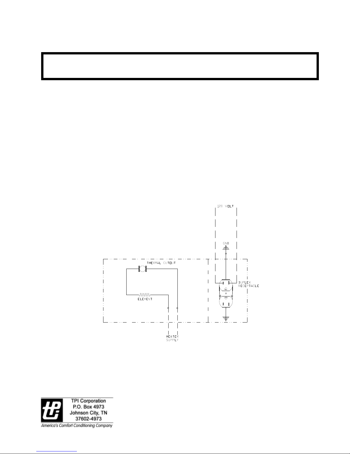
INST ALLATION INSTRUCTIONS
INBUIL T DUPLEX RECEPT ACLE
CAUTION: Disconnect supply service to baseboard and receptacle to avoid electrical shock. All
wiring connections must conform to National Electric Code and Local Codes having
jurisdiction.
NOTE: The receptacle must be conncted to a branch circuit, other than the baseboard heater
circuit, having over current protection in accordance with the National Electric Code.
1.The receptacle cover assembly can be mounted in the left or right hand junction box.
2.Remove baseboard heater junction box cover and retain screw.
3.Attach the 120V branch supply leads and ground lead the receptacle. Use copper conductors
only.
4.Install receptacle cover assembly to the baseboard junction box, secure with previously removed
screw.
5.Restore power and check for proper operation.
FORM: 9926
Page 5

Page 6

INST ALLATION INSTRUCTIONS
TRANSFER SWITCH WITH RECEPT ACLE SECTION
CAUTION: Disconnect supply service to avoid electrical shock. All wiring connections
must conform to national electric code and local codes having jurisdiction.
1. Remove front covers from accessory and baseboard.
2. Remove knockout for supply entrance and knockout from exposed end of baseboard
for heater wire entry.
3. Attach accessory to wall with heater, insert bushing (supplied) from baseboard junction
box.
4. Make connections per wiring diagram. Connect branch circuit conductors marked “line”,
connector conductors marked “heater” to heater load conductors.
5. Attach green ground lead from accessory to heater junction box for continuity of ground.
6. Reinstall heater junction box cover and accessory cover, restore power and check for
proper operation.
FORM: 9928
Page 7

Page 8

Page 9

INST ALLATION INSTRUCTIONS
WIRE WAY ADAPTER
CAUTION: Disconnect supply service to avoid electrical shock. All wiring must conform
to nation electric code and all local codes having jurisdiction.
1. Remove junction box covers.
2. Remove bottom knockouts on bottom of junction boxes on heat shield side. Insert
snap bushings provided.
3. Using means to protect finish, place baseboard face down. Lay wires in bottom of
baseboard and feed wire through bushings into junction box allowing minimum of 6”
wire into each box.
4. Attach wire way adapter to baseboard with screws provided.
5. Mount baseboard to wall (refer to baseboard installation instructions).
6. Complete wiring connections inside junction boxes for continuous parallel wiring.
7. Reinstall junction box covers and check heater(s) for proper operation.
INSTRUCTIONS FOR PRE-INST ALLED WIRE W AY ADAPTER
1. Remove junction box covers.
2. Using means to protect finish, place baseboard face down. Remove the adapter
retaining screws and adapter.
3. Lay wires in bottom of baseboard and feed through bushings into junction box allowing
minimum of 6” wire into each box.
4. Re-install wire way adapter and secure with previously removed screws. Proceed with
Steps 5, 6 and 7 above.
SCREW
BASEBOARD
BACK
WRAPPER
WIREWAY ADAPTOR
FORM: 9932
Page 10

INSTALLATION INSTRUCTIONS
BASEBOARD BLANK SECTION
CAUTION: Disconnect supply service to avoid electrical shock.
All wiring connections must conform to national electrical codes having
jurisdiction.
NOTE: The baseboard blank section mounts against the wall similar to the
baseboard. When making wiring connection: for wiring single baseboard and
the supply is through the blank section or when wiring for continuous
parallel connections for multiple baseboard installation, then a wire way
adapter must be used. (See wire way adapter installation instructions).
1. Remove appropriate junction box covers from baseboard(s) and
blank section.
2. Remove knockouts from heat shield side of junction boxes as
required, insert snap bushing(s).
Attach green ground lead(s) from baseboard blank section to
baseboard junction boxes for continuity of ground.
9. Reinstall all junction box covers.
FORM: 9933
Page 11

INST ALLATION INSTRUCTIONS
DISCONNECT SWITCH
CAUTION: Disconnect supply service to avoid electrical shock. All wiring must conform
to nation electric code and all local codes having jurisdiction.
NOTES:
* Do not eliminate or bypass the thermal cutout.
* Do not exceed the name plate rating.
* The in-built accessory can be mounted in either end of baseboard.
1. Remove junction box cover, ret ain screw.
2. Remove wire nut in junction box (Do not disturb the crimp nut connection).
3. Make connections per wiring diagram. Connect red lead wires to line supply and black
lead wires to load.
4. Install disconnect switch cover assembly to baseboard junction box and secure with
screw previously removed.
5. Restore power and check for proper operation.
FORM: 9934
Page 12

INSTALLATION INSTRUCTIONS
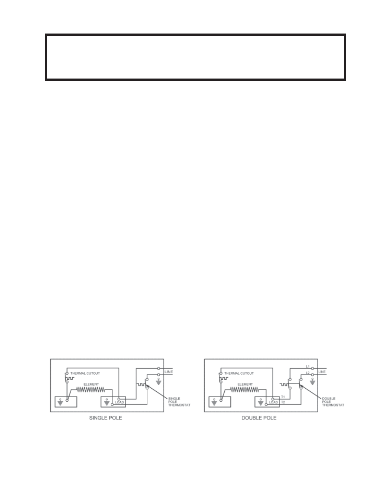
COVER MOUNTED BUIL T-IN THERMOST A T ACCESSORY
CAUTION: DISCONNECT SUPPL Y SERVICE T O A VOID ELECTRIC SHOCK. ALL WIR-
ING CONNECTIONS MUST CONFORM TO NATIONAL ELECTRIC CODE AND LOCAL
CODES HA VING JURISDICTION.
NOTES:
• Do not eliminate or bypass the thermal cutout.
• Be sure load controlled by the thermostat does not exceed the thermostat nameplate rating.
• The built-in thermostat accessory can be mounted in either end of the baseboard.
1. Assemble thermostat to one of the covers provided as shown in Fig. 1.
2. Remove junction box cover. Retain cover screw .
3 . Remove wire nut in junction box (Do Not Disturb Crimp Connection).
4. Make Connections per wiring diagram:
• SINGLE POLE: Connect read lead wire to supply line and black leadwire to load.
• DOUBLE POLE: Connect L1, L2 to supply line and T1, T2 to load.
5. Dress wiring into junction box. Install thermostat / mounting cover to junction box, secure with
screws previously removed to maintain ground continuity .
6. Press control knob onto thermostat shaft, restore power to baseboard.
7. Thermostat Operation: Turn thermostat control knob fully clockwise, when room temperature has
reached desired comfort level, slowly turn thermostat control knob counterclockwise until heater
turns off (a faint click may be heard). One or two minor adjustments may be required.
T AMPER RESIST ANT THERMOST A T INST ALLA TION:
Repeat steps 1, 2, 3, 4, 5.
1. With a small blade screwdriver , pry the snap bushing from the front cover. Restore power to
baseboard.
2. With a small blade screwdriver, adjust the thermost at shaft per step 6. Re-install snap bushing.
FORM: 9946
REV . 12/03
Page 13

LIMITED WARRANTY
Products manufactured by TPI Corporation are warranted to the original consumer to be free from defects in
material and workmanship for twelve (12) months from the original purchase date.
The TPI limited warranty does not cover products that have been modified outside of our factory, damage or
failure caused by acts of God, abuse, misuse, connected to or placed on other than rated voltage, abnormal
usage, fault, installation, failure to follow suggested maintenance procedures enclosed with the product,
improper maintenance or any repairs other than those provided by an authorized TPI service center .
There are no obligations or liabilities on the part of the Corporation for consequential damages arising out of or in connection with the use or performance of the product or other indirect damages with
respect to loss of property , revenues, profit, cost s of removal inst allation, or reinst allation.
All implied warranties with respect to TPI products, including implied warranties for merchantability
and implied warranties for fitness, are limited in duration to twelve (12) months from original date of
purchase, except those products or part s of product s which are warranted for long periods thereon.
Some states do not allow the exclusions or limitation of incidental or consequential damages and some
states do not allow limitations on how long an implied warranty lasts. The above exclusions or limit ations may
not apply to you.
During the warranty period, TPI Corporation will, at its sole option, repair or replace any defective parts or
products returned, freight prepaid, to the TPI Corporation factory or such other locations as TPI Corporation
may designate. Returned products must be packaged carefully and TPI Corporation shall not be responsible
for damage in transit.
When returning parts, the owner must provide the model number of the product and nature of difficulty being
experienced. This warranty does not obligate TPI Corporation to bear the cost of labor in replacing any
assembly , unit or component part thereof, nor does the company assume any liability for secondary charges,
expenses for installing or removal, freight or damages. There will be charges rendered for product repairs
made after the warranty period has expired. Proof of purchase, including date, must accompany request for
in-warranty service. In any event, TPI Corporation’s maximum liability shall not in any case exceed the list
price for the product claimed to be defective. This warranty gives to you specific legal rights and you may
have other rights, which may vary from state to state. For the name of your nearest authorized TPI Corporation service center, please write to TPI Corporation, P.O. Box 4973, Johnson City , TN 37602.
Heating Products Warranty Coverage
Elements in Baseboards
All Other Heating Products
Thermostats and Controls
10 Years
1 Year
2 Years
Ventilation Products Warranty Coverage
Series HD or HDH Fans
Series UHP or IHP Fans
All other Ventilation Products
5 Years
3 Years
1 Year
Rev . 1 1/20/03
FORM: 9882
 Loading...