

Page 1
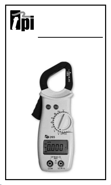
265
Digital Clamp-on
Meter Instruction Manual
Page 2

TABLE OF CONTENTS
A. INTRODUCTION
1. Congratulations ..........................3
2. Product Description....................3
3. Declaration of Conformity ..........4
B. SAFETY CONSIDERATIONS ..............5
C. TECHNICAL DATA
1. Features and Benefits..................6
2. Product Applications ..................7
3. Specifications ........................8-10
D. MEASUREMENT TECHNIQUES
1. Controls and Functions ......11-13
2. Step by Step Procedures:....14-21
E. OTHER FEATURES ..........................22
F. APPLICATION NOTES ................23-26
G. TROUBLE SHOOTING GUIDE ..........27
H. MAINTENANCE ................................28
I. ACCESSORIES ................................29
2
Page 3

A. INTRODUCTION
1. Congratulations!!
Thank you for purchasing TPI products. The 265 is easy
to use and is built to last. It is backed by a 3 year limited warranty. Please remember to complete and return
your product warranty registration card.
2. Product Description
The 265 is a hand-held, autoranging clamp-on DMM.
Extra large numerals, capacitance, frequency and data
hold are just a few of the features of the 265. An
affordable choice, the 265 offers measurements in all
basic electrical functions.
The 265 comes complete with the following accessories:
Carrying Pouch
Test Lead Set
Instruction Manual
Battery
3
Page 4

3. EC Declaration of Conformity
This is to certify that TPI Model 265 conforms to the
protection requirements of the council directive
89/336/EEC, in the approximation of laws of the member
states relating to Electromagnetic compatibility and
73/23/EEC. The Low Voltage Directive by application of
the following standards:
EN 50081-1 1992 Emissions Standard
EN 50082-1 1992 Immunity Standard
EN 61010-1 1993 Safety Standard
EN 61010-2-031 1995 Safety Standard
EN 61010-2-032 1995 Safety Standard
To ensure conformity with these standard, this instrument must be operated in accordance with the instructions and specifications given in this manual.
CAUTION: Even though this instrument complies with
the immunity standards, it’s accuracy can be affected
by strong radio emissions not covered in the above
standards. Sources such as hand-held radio transceivers, radio and TV transmitters, vehicle radios and
cellular phones generate electromagnetic radiation
that could be induced into the test leads of this instrument. Care should be taken to avoid such situations or
alternatively, check to make sure that the instrument is
not being influence by these emissions.
CAUTION: Please follow manufacturers test procedures whenever possible. Do not attempt to measure
unknown voltages or components until a complete
understanding of the circuit is obtained.
4 5
Page 5

B. SAFETY CONSIDERATIONS
WARNING: Please follow manufacturers test
procedures whenever possible. Do not attempt
to measure unknown voltages or components until a
complete understanding of the circuit is obtained.
GENERAL GUIDELINES
ALWAYS
• Test the 265 before using it to make sure it is
operating properly.
• Inspect the test leads before using to make sure there
are no breaks or shorts.
• Double check all connections before testing.
• Have someone check on you periodically if
working alone.
• Have a complete understanding of the circuit
being measured.
• Disconnect power to circuit, then connect test leads to
the 265, then to circuit being measured.
NEVER
• Attempt to measure unknown high voltages.
• Attempt to measure DC microamps with the meter in
parallel to the circuit.
• Connect the test leads to a live circuit before
setting up the instrument.
• Touch any exposed metal part of the test lead assembly.
Page 6

INTERNATIONAL SYMBOLS
CAUTION: RISK OF ELECTRIC SHOCK
AC (Alternation Current)
DC (Direct Current)
REFER TO INSTRUCTION MANUAL
GROUND
DOUBLE INSULATION
EITHER DC OR AC
C. TECHNICAL DATA
1. Features and Benefits
Agency Meets CE and IEC 1010.
Auto Off Automatically powers off after 10
minutes of inactivity. When active,
APO is displayed on the LCD.
NOTE: To disable Auto Off, hold
down the RANGE button while
turning on the 265.
6 7
Page 7

2. Product Applications
Perform the following tests and/or measurements with
the 265 and the appropriate function:
HV
AC/R
DCmV • Thermocouples in furnaces.
ACA • Heat anticipator current in thermostats.
ACV • Line voltage.
ACV or DCV • Control circuit voltage.
OHMS • Compressor winding resistance.
OHMS • Continuity of wiring.
CAP • Motor start and run capacitors.
ACA • Motor and compressor start up current.
Hz • Frequency on controls and line voltage.
ELECTRICAL
ACV • Measure line voltage.
ACA • Measure line current.
OHMS • Continuity of circuit breakers.
DCV • Voltage of direct drive DC motors.
ACA • Start up current of motors, relays,
contactors and transformers.
ELECTRONIC
ACV • Measure power supply voltage.
ACA • Measure power supply current.
OHMS • Continuity of circuit breakers and fuses.
Page 8
3. Specifications
IEC 1010 Over Voltage:
CAT II - 1000V
CAT III - 600V
Pollution Degree 2
Temperature for gauranteed accuracy: 23ºC +
5ºC
DC VOLTS
Range Res. Accuracy
400mV 0.1mV
+/-(0.3% of reading + 5 digits) Impedance:
4V 0.001V 10MΩ
40V 0.01V +/-(0.5% of reading + 4 digits) Overload Protection:
400V 0.1V 600VDC or AC RMS
600V 1V +/-(1.0% of reading + 4 digits)
(40Hz to 60Hz Frequency Response 400mV Range)
AC VOLTS
(40Hz to 400Hz Frequency Response All Other Ranges)
Range Res. Accuracy
400mV 0.1mV +/-(1.5% of reading + 5 digits) Impedance:
4V 0.001V
10MΩ
40V 0.01V
+/-(1.5% of reading + 5 digits) Overload Protection:
400V 0.1V
600VDC or AC RMS
600V 1V
8
UL 3111 Pending
(45Hz to 100Hz Frequency Response 200A to 400A)
AC AMPS (45Hz to 450Hz Frequency Response Below 200A)
Range Res. Accuracy
40A 0.01A
+/-(3.0% of reading + 5 digits)
400A 0.1A e
Page 9
9
OHM (Resistance, Ω)
Range Res. Accuracy
400Ω 0.1Ω
4kΩ 0.001kΩ
±(0.8% of reading +5 digits)
Overload Protection:
40kΩ 0.01kΩ 250VDC or AC RMS
400kΩ 0.1kΩ
4MΩ 0.001MΩ
±(2% of reading +10 digits)
40MΩ 0.01MΩ
Frequency (Hz)
Range Res. Accuracy
4000Hz 1Hz
40.00kHz 0.01kHz
400.0kHz 0.1kHz
±(0.5% of reading +2 digits) Overload Protection:
4.000MHz 0.001MHz 250VDC or AC RMS
40.00MHz 0.01MHz
Diode Test
Test Current Over Load Protection
1.5mA MAX 250 V DC or AC RMS
Continuity Buzzer
Test Voltage Threshold Over Load Protection
3V <35Ω 250 V DC or AC RMS
Page 10

10
Capacitance
Range Res. Accuracy
4nF 0.001nF
40nF 0.01nF
400nF 0.1nF
Overload Protection:
4µF 0.001µF ±(3% of reading +10 digits) 500VDC or AC RMS
40µF 0.01µF
400µF 0.1uF
4mF 0.001mF ±(7% of reading +10 digits)
nF= nanofarad, µF= microfarad, mF= millifarad
General
Max Voltage between any 600V
input and ground
Fuse Protection (µµA range) 0.5A/600V
Display Type 4000 Count 41 seg. bargraph
Operating Temperature 32ºF to 113ºF (0ºC to 40ºC)
Storage Temperature -4ºF to 140ºF (-20ºC to 60ºC)
Relative Humidity 80% non-condensing
Power Supply 9V (MN1604)
Battery Life 80 hrs. typical
Size (H x L x W) 32.5mm x 255mm x 65mm
(1.3in x 10in x 2.5in)
Weight 363g (0.8lbs)
Page 11

11
Jaws for Measuring
AC Amps Only
RANGE
Push Button
HOLD Push
Button
Rotary
Switch
LCD Display
with Function
Annunciators
Input Jacks
Trigger for
Opening
the Jaws
D. MEASUREMENT TECHNIQUES
1. Controls and Functions:
Page 12

12
Controls and Functions: (cont.)
Push Buttons
HOLD Holds the reading on the display
until the button is pushed a
second time.
RANGE Activates manual ranging. Press and
hold for 2 seconds to return to auto
ranging.
Rotary Switch
OFF Turns the 265 completely off.
V Used to measure DC volts.
V Used to measure AC volts.
ΩΩ
Used to measure resistance.
Used to measure continuity.
Selects diode test function.
Selects capacitance test function.
Hz Selects frequency test function.
Used to measure AC amperage.
Page 13

13
Controls and Functions: (cont.)
Input Jacks
COM Black test lead connection for all
measurements except AC Amps.
V/ΩΩ/ /Hz Red test lead connection for all
measurements except AC Amps.
Page 14

14
2. Step by Step Procedures:
Measuring DC Voltage
WARNING!
Do not attempt to make a voltage measurement of more
than 600V or of a voltage level that is unknown. Make sure
the temperature probe is NOT
plugged in during this test.
Instrument set-up:
FUNC. BLACK RED MIN MAXI
TEST LEAD TEST LEAD READING READING
COM V/Ω 0.1mV 600V
Measurement Procedure:
1. Disconnect power to circuit to be measured.
2. Plug black test lead into the COM input jack.
3 Plug red test lead into the V/Ω input jack.
4. Set rotary switch to the V range.
5. Connect test leads to circuit to be measured.
6. Reconnect power to circuit to be measured.
7. Read the voltage on the 265.
Optional Modes
• HOLD: Freezes the reading on the LCD.
• RANGE: Activates manual ranging. Press and hold for
2 seconds to return to auto ranging.
Page 15

Measuring AC Voltage
WARNING!
Do not attempt to make a voltage measurement of more than
600V or of a voltage level that is unknown. Make sure the temperature probe is NOT plugged in during this test.
Instrument set-up:
FUNC. BLACK RED MIN MAX
TEST LEAD TEST LEAD READING READING
COM V/Ω 0.1mV 600V
Measurement Procedure:
1. Disconnect power to circuit to be measured.
2. Plug black test lead into the COM input jack.
3 Plug red test lead into the V/Ω input jack.
4. Set rotary switch to the V range.
5. Connect test leads to circuit to be measured.
6. Reconnect power to circuit to be measured.
7. Read the voltage on the 265.
Optional Modes
• HOLD: Freezes the reading on the LCD.
• RANGE: Activates manual ranging. Press and hold for
2 seconds to return to auto ranging.
15
Page 16

16
Measuring Resistance
WARNING!
Do not attempt to make resistance measurements with circuit
energized. For best results, remove the resistor completely from
circuit before attempting to measure it. Make sure the temperature probe is NOT plugged in during this test.
NOTE:
To make accurate low ohm measurements, short the ends of the
test leads together and press the REL button to store the reading.
This will deduct the stored value from subsequent measurements
eliminating the test lead resistance from the reading.
Instrument set-up:
FUNC. BLACK RED MIN MAX
TEST LEAD TEST LEAD READING READING
Ω COM V/Ω 0.1Ω 40.00MΩ
Measurement Procedure:
1. Disconnect power to circuit to be measured.
2. Plug black test lead into the COM input jack.
3. Plug red test lead into V/Ω input jack.
4. Set the rotary switch to the Ω function.
5. Connect test leads to circuit to be measured.
6. Read the resistance value on the 265.
Optional Modes
• HOLD: Freezes the reading on the LCD.
• RANGE: Activates manual ranging. Press and hold for
2 seconds to return to auto ranging.
Page 17

17
Measuring AC Amperage
CAUTION!
Do not attempt to make a current measurement with the
test leads. The 265 measures the current by clamping the
jaw around one conductor (wire). Clamping around more
than one wire will result in erroneous readings. Make sure
the temperature probe is NOT plugged in during this test.
Instrument set-up:
FUNC. BLACK RED MIN MAX
TEST LEAD TEST LEAD READING READING
NOT USED NOT USED 0.01A 400A
Measurement Procedure:
1. Disconnect power to circuit to be measured.
2. Set rotary switch to function.
3. Clamp the jaws around one conductor of the circuit to
be measured. For best results, center the wire in the
jaw.
4. Reconnect power to circuit to be measured.
5. Read the current on the 265.
Optional Modes
• HOLD: Freezes the reading on the LCD.
• RANGE: Activates manual ranging. Press and hold for
2 seconds to return to auto ranging.
Page 18

18
Measuring Continuity
WARNING!
Do not attempt to make continuity measurements with circuit
energized. Make sure the temperature probe is NOT plugged
in during this test.
Instrument set-up:
FUNC. BLACK RED
TEST LEAD TEST LEAD
COM V/Ω
Measurement Procedure:
1. Disconnect power to circuit to be measured.
2. Plug black test lead into the COM input jack.
3. Plug red test lead into V/Ω input jack.
4. Set the rotary switch to the position.
5. Connect test leads to circuit to be measured.
6. The 265 will beep and the LED will illuminate at
resistances of 35Ω or lower.
Optional Modes
• HOLD: Freezes the reading on the LCD.
Page 19
Measuring Diodes
WARNING!
Do not attempt to make diode measurements with the circuit
energized. For accurate tests, remove the diode completely
from the circuit prior to measuring it. Make sure the temperature probe is NOT plugged in during this test.
Instrument set-up:
FUNC. BLACK RED
TEST LEAD TEST LEAD
COM V/Ω/µA
Measurement Procedure:
1. Disconnect power to circuit to be measured.
2. Plug black test lead into the COM input jack.
3. Plug red test lead into V/Ω
input jack.
4. Set the rotary switch to the
5. Connect the black test lead to the banded end of the diode
(cathode) and the red test lead to the non-banded end of
the diode (anode).
6. For a good diode, the reading on the display should be
between 0.5V and 0.8V. The reading will be lower for a
germanium diode.
7. Reverse the leads on the diode.
8. For a good diode, the reading on the display should be OL
(overload).
Optional Modes
• HOLD: Freezes the reading on the LCD.
19
position.
Page 20

20
Measuring Capacitance
WARNING!
All capacitance measurements are to be made on de-energized
circuits with all capacitors discharged only. Failure to de-energize
and discharge capacitors prior to measuring them could result in
instrument damage and/or personal injury. Make sure the temperature probe is NOT plugged in during this test.
Instrument set-up:
FUNC. BLACK RED
TEST LEAD TEST LEAD
COM V/Ω/µA
Measurement Procedure:
1. Disconnect power to circuit to be measured.
2. Plug black test lead into the COM input jack.
3. Plug red test lead into V/Ω
input jack.
4. Set the rotary switch to the
5. Remove the capacitor from the circuit and discharge it.
6. Connect test leads to the capacitor to be measured.
Observe polarity on polarity sensitive capacitors.
7. Read the capacitor value on the LCD.
Optional Modes
• HOLD: Freezes the reading on the LCD.
• RANGE: Activates manual ranging. Press and hold for
2 seconds to return to auto ranging.
position.
Page 21

21
Measuring Frequency
WARNING!
Never attempt a frequency measurement with a voltage source
greater than 500V. Determine the voltage of any unknown frequency source before connecting the instrument in frequency
mode. Make sure the temperature probe is NOT
plugged in
during this test.
Instrument set-up:
FUNC. BLACK RED
TEST LEAD TEST LEAD
Hz COM V/Ω/µA
Measurement Procedure:
1. Disconnect power to the circuit to be measured.
2. Plug black test lead into the COM input jack.
3. Plug red test lead into V/Ω input jack.
4. Set the rotary switch to the Hz position.
5. Reconnect power to the circuit to be measured.
6. Read the frequency on the LCD.
Optional Modes
• HOLD: Freezes the reading on the LCD.
• RANGE: Activates manual ranging. Press and hold for
2 seconds to return to auto ranging.
Page 22

22
E. Other Features
Manual Ranging (RANGE)
The range hold button (RANGE) activates manual ranging.
Press the RANGE button to cycle through available ranges.
Pressing and holding the RANGE button for approximately two
seconds returns the meter to autorange mode and “auto” will
be displayed in the upper left corner of the display.
Data Hold (HOLD)
Press the HOLD button at any time to freeze the reading on the
LCD display. This function is useful when measuring in
locations where the display is difficult to read.
Auto Power Off (APO)
Automatically powers off after 10 minutes of inactivity. When
active, APO is displayed on the LCD.
NOTE: To disable Auto Off, hold down the RANGE
button while turning on the 265.
Page 23

23
F. Application Notes (AC Volts)
Disconnect power from the
terminal block, find the fuse
or circuit breaker that controls the block and turn it
off.
Set up the meter following
the steps under
“Measurement Procedure”
on page 15. Then proceed with
the following:
•Connect the red test lead to
the hot side of the block and
the black lead to the neutral
side of the block. Reconnect
power to the block and read
the voltage on the meter. The
reading should be approximately 110V to
130V.
• Disconnect power from the block and move
the red wire to ground. Reconnect power to
the block and read the voltage on the meter.
Typically less than 20V should exist from
neutral to ground. If 110V or above exists,
the block may be wired incorrectly.
Page 24

24
Application Notes (DC Volts)
The 265 will accurately measure rectified DC Voltages like
those encountered in furnaces and other appliances even
though many of these devices do not have output filtering
or other signal conditioning.
When measuring DC Voltage of a battery, the most accurate reading can be
attained by testing the battery under
load. To accomplish this, follow steps
1 through 4 shown on page 14 and
the following (with the battery in
holder and device turned on):
• Connect the red test lead from the
meter to the positive (+) terminal
of the battery.
• Connect the black test lead to the
negative (-) terminal of the battery.
Page 25
25
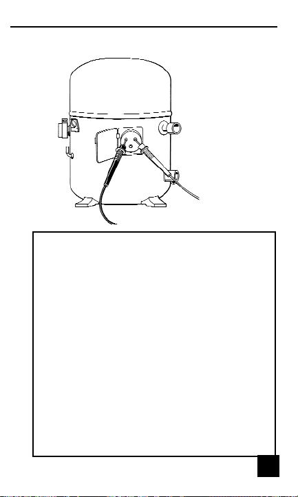
When measuring resistance of a motor, make
sure the power is disconnected prior to testing.
Set up meter following steps under
“Measurement Procedure” on page 16, and
proceed with the following:
• Connect the red test lead to one power
input line of the motor and the black test
lead to the other power input line of the
motor. In most applications if the reading
is OFL, the motor winding is open.
• Connect the red test lead to the frame of
the motor and the black test lead to the
winding. In most applications if a reading
of 0 Ohms is displayed, the winding is
shorted to the motor frame (ground).
Application Notes (Resistance)
25
Page 26

26
Application Notes (AC Amps)
When measuring AC Amps of a motor there
are two types of measurements that can be
made, running current and in-rush or start-up
current. Start-up current will usually be much
higher than running current.
Set up the meter following the steps under
“Measurement Procedure” on page 17, and
then proceed with the following:
• Clamp the meter around a single wire
and reconnect power to the device. Read
the current displayed on the meter. This
is the running current of the motor.
• Disconnect power to the motor and put
the meter in PEAK HOLD mode.
Reconnect the power and read
the current displayed on the
meter. This is the in-rush or
start-up current
of the motor.
Page 27

27
G. Trouble Shooting
Problem
Probable Causes
Does not power up
• Dead or defective battery
• Broken wire from battery
snap to PCB
All functions except
• Very weak battery that will
ohms read high
not turn on the low battery
indicator on the LCD
AC Volts do not read
• Very weak battery that will
not turn on the low battery
indicator on the LCD
AC Amps does not read
• Make sure the jaw is clamped
around a single wire and the
device connected to the wire is
turned on.
Page 28

28
H. Maintenance
1. Battery Replacement: The 265 will display a battery
symbol when the internal 9 Volt battery needs replacement. The battery is replaced as follows:
a. Disconnect and remove all test leads
from live circuits and from the 265.
b. Loosen the screw from the back of the 265 battery
cover.
c. Remove the battery compartment cover.
d. Remove old battery and replace with new battery.
Observe the correct polarity on the battery.
e. Reassemble the instrument in reverse
order from above.
2. Cleaning your 265:
Use a mild detergent and slightly damp cloth to clean the
surfaces of the 265.
Page 29

29
Accessories
Standard Accessories Part Number
9 Volt Alkaline Battery A009A
Test Lead Set A040
Soft Carrying Pouch A255
Optional Accessories
Part Number
Fused Test Lead Kit FTLK3
Deluxe Test Lead Set TLS2000RB
Carbon Monoxide Adapter A771
Pressure Adapter A620
Temperature Adapter A301
Differential Temperature Adapter A312
Page 30

30
Notes:
Page 31

31
Notes:
Page 32

Func. Range
Res.
DCV 400mV 0.1mV
4V 0.001V
40V 0.01V
400V 0.1V
600V 1V
ACV 400mV 0.1mV
4V 0.001V
40V 0.01V
400V 0.1V
750V 1V
ACA 40A 0.1A
400A 1A
OHM 400Ω 0.1Ω
4kΩ 0.001kΩ
40kΩ 0.01kΩ
400kΩ 0.1kΩ
4MΩ 0.001MΩ
40MΩ 0.01MΩ
Capacitance 4nF 0.001nF
40nF 0.01nF
400nF 0.1nF
4uF 0.001uF
40uF 0.01uF
400uF 0.1uF
4mF 0.001mF
Frequency 4000Hz 1Hz
40.00kHz 0.01kHz
400.0kHz 0.1kHz
4.000MHz 0.001MHz
40.00MHz 0.01MHz
265 SPECIFICATIONS (PARTIAL LIST)
±0.5% Basic DCV Accuracy
Test Products International, Inc.
9615 SW Allen Blvd., Ste. 104
Beaverton, OR USA 97005
503-520-9197 • Fax: 503-520-1225
info@tpi-thevalueleader.com
L265M • 1/25/05 copyright © 2005 Test Products International, Inc.
 Loading...