

Page 1
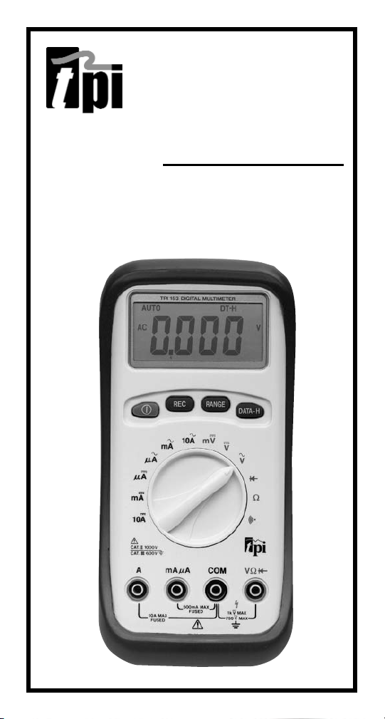
153
Digital Multimeter
Instruction Manual
Page 2

TABLE OF CONTENTS
A. INTRODUCTION
1. Congratulations . . . . . . . . . . . . . . . . . .3
2. Product Description . . . . . . . . . . . . . .3
3. EC Declaration of Conformity . . . . . . . .4
B. SAFETY CONSIDERATIONS . . . . . . . . . . . .5
C. TECHNICAL DATA
1. Features and Benefits . . . . . . . . . . . . .6
2. Product Applications . . . . . . . . . . . . . .7
3. Specifications . . . . . . . . . . . . . . . . . . .8
D. MEASUREMENT TECHNIQUES
1. Controls and Functions . . . . . . . . . .10
2. Step by Step Procedures:
a) Measuring DC Volts . . . . . . .13
b) Measuring AC Volts . . . . . . .15
c) Measuring DC Amps . . . . . .16
d) Measuring AC Amps . . . . . .17
e) Measuring Resistance . . . . .19
f) Measuring Diodes . . . . . . . .20
g) Continuity Buzzer . . . . . . . .21
h) Data Hold . . . . . . . . . . . . . .21
i) Record Mode . . . . . . . . . . .22
page
E. ACCESSORIES . . . . . . . . . . . . . . . . . . . . .23
F. MAINTENANCE . . . . . . . . . . . . . . . . . . . .24
G. TROUBLE SHOOTING GUIDE . . . . . . . . . .25
2 3
Page 3

A. INTRODUCTION
1. Congratulations!!
Thank you for purchasing TPI brand products. The meter is
easy to use and is built to last. It is backed by a 3 year
limited warranty. Please remember to complete and return
your product warranty registration card.
2. Product Description
The 153 is a hand-held autoranging DMM. The 153
measures ACV, DCV, ACA, DCA, Resistance, Diodes and
Continuity.
The 153 also features:
• REC Records Min/Max readings during
specified measurement intervals.
• RANGE Allows the user to manually range the
153 instead of autoranging.
• Data Hold Holds the reading on the display for
easy viewing.
• Auto Off Preserves battery life.
The 153 comes complete with the following accessories:
153 Instrument
Rubber Boot
Test Lead Set
Instruction Manual
Battery
Page 4

3. EC Declaration of Conformity
This is to certify that model 153 conforms to the protection
requirements of the council directive 89/336/EEC, in the
approximation of laws of the member states relating to
Electromagnetic compatibility and 73/23/EEC, The Low
Voltage Directive by application of the following standards:
EN 50081-1 1992 Emissions Standard
EN 50082-1 1992 Immunity Standard
EN61010-1 1993 Safety Standard
EN61010-2-031 1995 Safety Standard
To ensure conformity with these standards, this instrument
must be operated in accordance with the instructions and
specifications given in this manual.
CAUTION:
Even though this instrument complies with the
immunity standards, the accuracy can be affected by strong radio emissions not covered in the
above standards. Sources such as hand held
radio transceivers, radio and TV transmitters,
vehicle radios and cellular phones generate
electromagnetic radiation that could be induced
into the test leads of this instrument. Care
should be taken to avoid such situations or
alternatively, check to make sure that the
instrument is not being influenced by these
emissions.
4
Page 5

B. SAFETY CONSIDERATIONS
WARNING: Please follow manufacturers test
procedures whenever possible. Do not attempt to
measure unknown voltages or components until a
complete understanding of the circuit is obtained.
GENERAL GUIDELINES
W
AYS
AL
• Test the 153 before using it to make sure it is
operating properly.
• Inspect the test leads before using to make sure
there are no breaks or shorts.
• Double check all connections before testing.
• Have someone check on you periodically if
working alone.
• Have complete understanding of circuit being
measured.
• Disconnect power to circuit then, connect test
leads to the 153, then to circuit being measured.
NEVER
• Attempt to measure unknown high voltages.
• Attempt to measure current with the meter in
parallel to the circuit.
• Connect the test leads to a live circuit before
setting up the instrument.
• Touch any exposed metal part of the test lead
assembly.
5
Page 6

INTERNATIONAL SYMBOLS
DANGEROUS VOLTAGE
AC (ALTERNATING CURRENT)
DC (DIRECT CURRENT)
REFER TO INSTRUCTION MANUAL
GROUND
FUSE
DOUBLE INSULATION
ON/OFF, PUSH BUTTON SWITCH
C. TECHNICAL DATA
1. Features and Benefits
Agency Approval Meets CE and IEC 1010 requirements.
UL Listed to U.S. and Canadian Safety
Standards.
Sleep Instrument automatically powers down
after 30 minutes of inactivity, however,
it will continue acquiring data in its
various modes. Pressing any push
button or turning the rotarty switch
returns the 153 back to normal.
Record Records Min/Max values.
Range Allows you to either manual range or
use auto range to select the appropriate range.
Auto Off Preserves battery life. LCD shows oFF
when in this mode.
3 Year Covered by a standard 3 year warranty.
Warranty
Page 7

2. Product Applications
Perform the following tests and/or measurements
with the TPI 153 and the appropriate function:
HVAC/R
FUNCTION
DCmV • Thermocouples in furnaces or gas
applications.
ACA • Heat anticipator current in thermostats.
ACV • Line voltage.
ACV or DCV • Control circuit voltage.
DCµA • Flame safeguard control current.
OHMS • Heating element resistance (continuity).
OHMS • Compressor winding resistance.
OHMS • Contactor and relay coil resistance.
OHMS • Continuity of wiring.
DCmV • Temperature with optional temperature
adapter (A310).
ELECTRICAL
FUNCTION
ACV • Measure line voltage.
OHMS • Continuity of circuit breakers.
DCV • Voltage of direct drive DC motors.
76
Page 8
3. Specifications
IEC 1010 Over Voltage:
CAT II - 1000V
CAT III - 600V
Pollution Degree 2
UL 3111-1
a. DCV
Range Resolution Accuracy Impedance
400mV 0.1mV ±0.3% of reading, 10MΩ
4V 0.001V ±2 digits
40V 0.01V
400V 0.1V
1000V 1V
b. ACV (45Hz to 450Hz)
Range Resolution Accuracy Impedance
4V 0.001V ±0.8% of reading, 10MΩ
40V 0.01V ±3 digits
400V 0.1V ±1.2% of reading,
750V 1V ±3 digits
c. DCA
Range Resolution Accuracy Overload Protection
400µA 0.1µA ±0.5% of reading, Fuse
4mA 0.001mA ±2 digits 0.5Amp/600V
40mA 0.01mA
400mA 0.1mA
4A 0.001A ±1.2% of reading, Fuse
10A 0.01A ±2 digits 10Amp/600V
*Warning: Use only correct size, voltage and current rated fuses.
Test Leads: Use only correct type and overvoltage category rating.
8
Page 9
d. ACA (45Hz to 450Hz)
Range Resolution Accuracy Overload Protection
400µA 0.1µA ±0. 8% of reading, Fuse
4000µA 1µA ±3 digits 0.5Amp/600V
40mA 0.01mA
400mA 0.1mA
4A 0.001A ±1. 5% of reading, Fuse
10A 0.01A ±3 digits 10Amp/600V
e. OHM (Resistance,Ω)
Range Resolution Accuracy Overload Protection
400Ω 0.1Ω ±0. 5% of reading, 600V DC or
4kΩ 0.001kΩ ±2 digits AC Peak
40kΩ 0.01kΩ
400kΩ 0.1kΩ
4MΩ 0.001MΩ ±1% of reading,
40MΩ 0.01MΩ ±2 digits
f. Diode Test
Test Voltage Max Test Current Over Load Protection
3V Approx. 30µA 600 V DC or Peak AC
g. Continuity Buzzer
Test Voltage Threshold Over Load Protection
3V < 50Ω 600 V DC or Peak AC
h. General Specifications
Max. Volt. between 1000V
any Input and Ground
Fuse Protection mA: 0.5Amp/600VAC A: 10Amp/600VAC
Display Type 4,000 Count, 2 times per second update
Operating Temp. 0° to 40°C (32° to 104°F)
Storage Temp. -10° to 50°C (14° to 122°F)
Relative Humidity 0% to 80%
Power Supply 2 Each 1.5 Volt “AA” Batteries
Battery Life 200 hrs. Typical
Size (H x L x W) 33mm x 86mm x 187mm (1.3in x 3.4in x 7.4in)
Weight 340g (12oz)
9
Page 10

D. MEASUREMENT TECHNIQUES
1. Controls and Functions:
Push Buttons
Turns the 153 on and off.
REC Activates the Min/Max mode. Hold in for 3
seconds to deactivate.
RANGE Activates manual ranging. Hold in for 3 seconds
to return to autorange.
DATA-H Holds the reading on the display until the button
is pushed a second time.
Rotary Switch
µA Function for measuring microamps (µA) DC.
1 microamp = 0.000001Amp
mA Function for measuring milliamps (mA) DC.
1 milliamp = 0.001 Amp
10A Function for measuring DC Amps (A).
µA Function for measuring microamps (µA) AC.
1 microamp = 0.000001Amp
mA Function for measuring milliamps (mA) AC.
1 milliamp = 0.001Amp
10A Function for measuring AC Amps (A).
mV Function for measuring millivolts (mV) DC.
1 millivolt = 0.001 Volt.
V Function for measuring DC Volts.
V Function for measuring AC Volts.
Ω
Function for measuring Ohms (resistance.)
Function for testing Diodes.
Function for using audible Continuity Buzzer.
Page 11
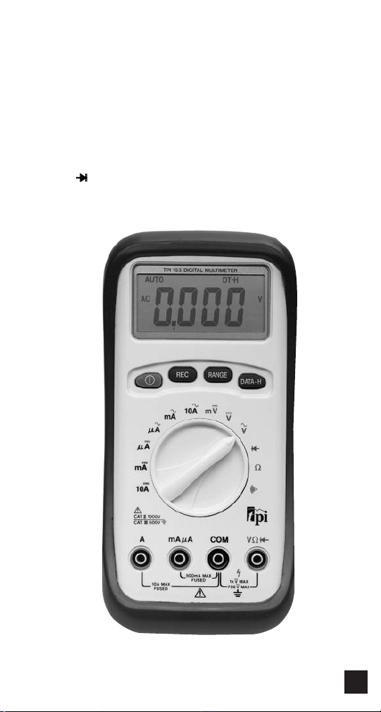
1. Controls and Functions: (cont.)
Input Jacks
A Red test lead connection for current
measurements on the A and A functions.
mAµA Red test lead connection for current
measurement on the mA and mA functions.
COM Black test lead connection for all functions.
Ω
V
Red test lead connection for all Volt, Ohm, Diode
and Continuity measurements.
1110
Page 12
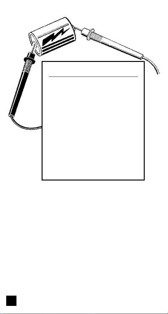
Application Notes
When measuring DC Voltage of a battery, the most accurate reading can be
attained by testing the battery under
load. To accomplish this, follow steps 1
through 4 shown on page 10 and the
following:
• Connect the red test lead from the
meter to the positive (+) terminal of
the battery.
• Connect the black test lead to the
negative (-) terminal of the battery.
• Reconnect power to the circuit and
read the voltage on the 153.
Page 13

2. Step by Step Procedures:
a. MEASURING DC VOLTS
CAUTION!
Do not attempt to make a voltage measurement
if a test lead is plugged in the A or µmA input
jack. Instrument damage and/or personal
injury may result.
ARNING!
W
Do not attempt to make a voltage measurement
of more than 1000V or of a voltage level that is
unknown.
Instrument set-up:
FUNCTION BLACK RED MINIMUM MAXIMUM
mV COM VΩ 0.1mV 400.0mV
V COM VΩ 0.001V 1000V
TEST LEAD TEST LEAD READING READING
Measurement Procedure:
1. Disconnect power to the circuit to be measured.
2. Plug the black test lead into the COM input jack.
3 Plug red test lead into the VΩ input jack.
4. Set rotary switch to either the mV or V range,
depending on the voltage to be measured.
5. Connect the test leads to the circuit to be measured.
6. Reconnect power to the circuit to be measured.
7. Read the voltage on the 153.
1312
Page 14

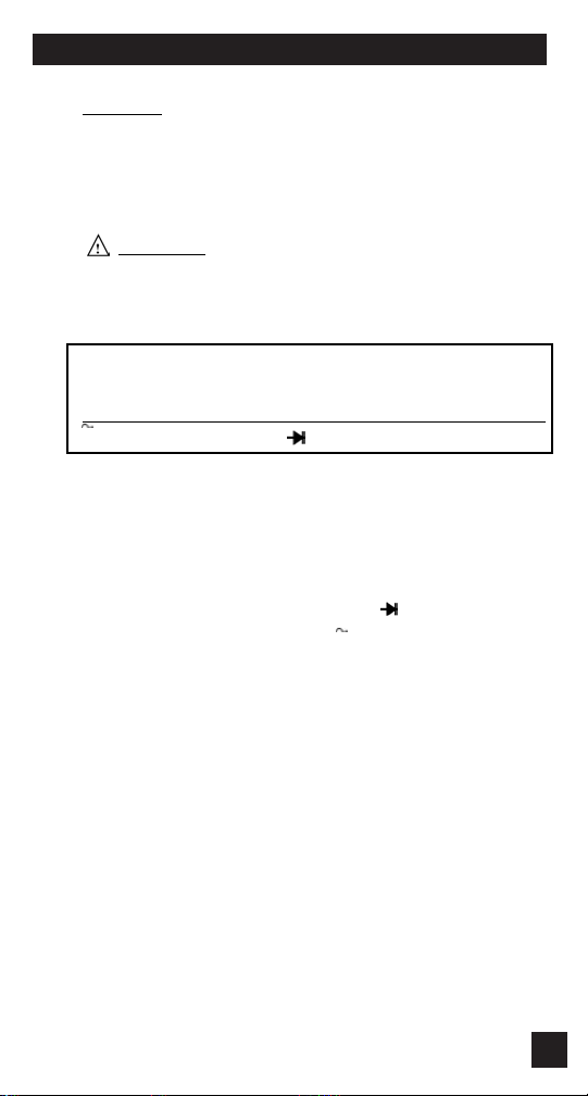
Application Notes
When measuring the AC voltage of a standard
household outlet, remember that the small
rectangular hole is hot, the larger rectangular hole
is neutral and the round hole is ground.
To disconnect power from the outlet, find the fuse or
circuit breaker that controls the outlet and turn it off.
Set up the meter following the steps under
“Measurement Procedure” on page 13.
Then proceed with the following:
• Connect the red test lead to the hot side of
the outlet and the black lead to the neutral
side of the outlet. Reconnect power to the
outlet and read the voltage on the meter.
The reading should be approximately 110V
to 130V.
• Disconnect power from the outlet and
move the red wire to the ground hole.
Reconnect power to the outlet and read the
voltage on the meter. Typically less than
20V should exist from neutral to ground. If
110V or above exists, the outlet may be
wired incorrectly.
Page 15
b. MEASURING AC VOLTS
CAUTION!
Do not attempt to make a voltage measurement
if a test lead is plugged in the A or µmA input
jack. Instrument damage and/or personal injury
may result.
ARNING!
W
Do not attempt to make a voltage measurement
of more than 750V or of a voltage level that is
unknown.
Instrument set-up:
FUNCTION BLACK RED MINIMUM MAXIMUM
V COM VΩ 0.001V 750V
TEST LEAD TEST LEAD READING READING
Measurement Procedure:
1. Disconnect power to the circuit to be measured.
2. Plug the black test lead into the COM input jack.
3. Plug the red test lead into the VΩ input jack.
4. Set the rotary switch to the V function depending on
the voltage to be measured.
5. Connect the test leads to the circuit to be measured.
6. Reconnect power to the circuit to be measured.
7. Read the voltage on the 153.
1514
Page 16
C. MEASURING DC AMPS
CAUTION!
Do not attempt to make a current measurement with the
test leads connected in parallel with circuit to be tested.
Test leads must be connected in series with the circuit.
ARNING!
W
Do not attempt to make a current measurement of
circuits with more than 600V present. Instrument
damage and /or personal injury may result.
Instrument set-up:
FUNCTION BLACK RED MINIMUM MAXIMUM
µA COM mAµA 0.1µA 4000µA
mA COM mAµA 0.01mA 400mA
10A COM A 0.001A 10.00A
TEST LEAD TEST LEAD READING READING
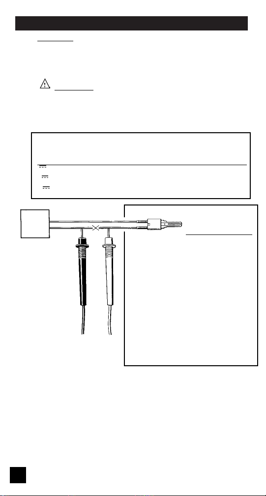
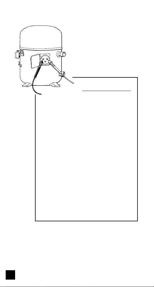
Application
Notes
When measuring the DC current of a
flame controller, follow the steps
under “Measurement Procedure”
below and then proceed with the
following:
• Set up the meter for making a
mA measurement.
Measurement
Procedure:
1. Disconnect power
to circuit to be
measured.
2. Plug the black test lead into the COM input jack.
3. Plug the red test lead into the mAµA or A input jack
depending on the value of current to be measured.
4. Set the rotary switch to the µA, mA, or 10A function.
5. Connect test leads in series to circuit to be measured.
6. Reconnect power to the circuit to be measured.
7. Read the current on the 153.
• Connect the meter to the flame
controller lead by opening the
circuit and inserting the leads in
series with the circuit as shown
in the picture above.
Page 17
d. MEASURING AC AMPS
CAUTION!
Do not attempt to make a current measurement
with the test leads connected in parallel with the
circuit to be tested. Test leads must be connected
in series with the circuit.
ARNING!
W
Do not attempt to make a current measurement of
circuits with more than 600V present. Instrument
damage and /or personal injury may result.
Instrument set-up:
FUNCTION BLACK RED MINIMUM MAXIMUM
µA COM mAµA 0.1µA 4000µA
mA COM mAµA 0.01mA 400mA
10A COM A 0.001A 10.00A
TEST LEAD TEST LEAD READING READING
Measurement Procedure:
1. Disconnect power to the circuit to be measured.
2. Plug the black test lead into the COM input jack.
3. Plug the red test lead into the mAµA or A input jack
depending on the value of current to be measured..
4. Set the rotary switch to the µA, mA or 10A function.
5. Connect test leads in series to circuit to be measured.
6. Reconnect power to the circuit to be measured.
7. Read the current on the 153.
1716
Page 18
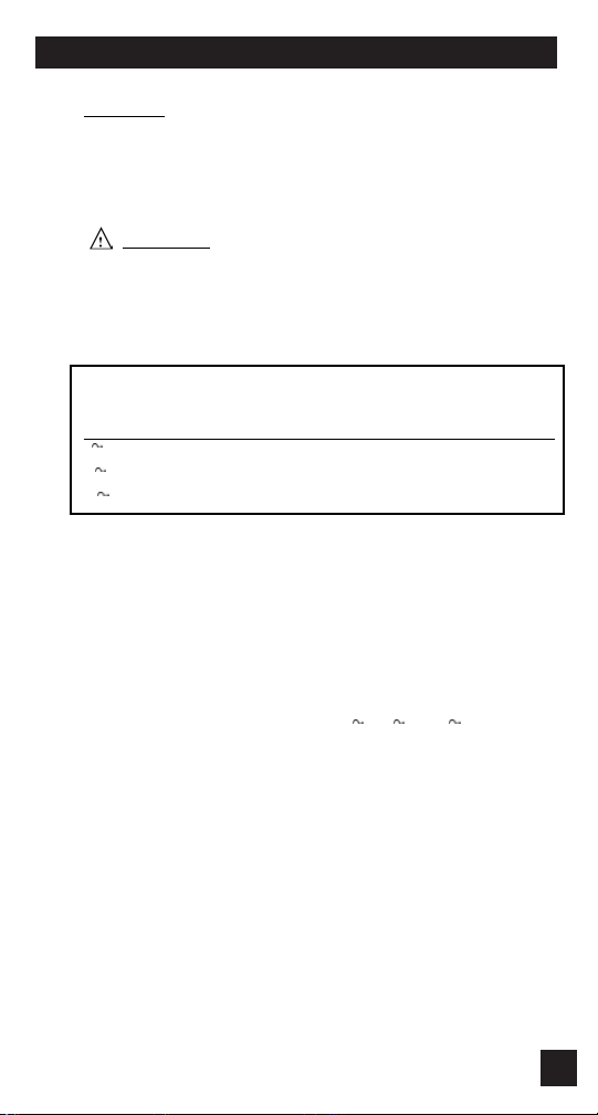
Application Notes
When measuring resistance of a motor,
make sure the power is disconnected prior
to testing.
Set up the meter following the steps under
“Measurement Procedure” on page 17, and
then proceed with the following:
• Connect the red test lead to one power
input line of the motor and the black
test lead to the other power input line
of the motor. In most applications, if
the reading is OFL, the motor winding
is open.
• Connect the red test lead to the frame
of the motor and the black test lead to
the winding. In most applications, if a
reading of 0 Ohms is displayed, the
winding is shorted to the motor frame
(ground).
Page 19

e. MEASURING RESISTANCE
WARNING!
Do not attempt to make resistance measurements
with circuit energized. For best results, remove
the resistor completely from the circuit before
attempting to measure it.
NOTE:
To make accurate low ohm measurements, short
the ends of the test leads together and record the
resistance reading. Deduct this value from
actual readings.
Instrument set-up:
FUNCTION BLACK RED MINIMUM MAXIMUM
Ω COM VΩ 0.1Ω 40.00MΩ
TEST LEAD TEST LEAD READING READING
Measurement Procedure:
1. Disconnect power to the circuit to be measured.
2. Plug the black test lead into the COM input jack.
3. Plug the red test lead into the VΩinput jack.
4. Set the rotary switch on the 153 to the Ωfunction.
5. Connect the test leads to the circuit to be measured.
6. Read the resistance value on the 153.
1918
Page 20
f. MEASURING DIODES
CAUTION!
Do not attempt to make diode measurements with
circuit energized. The only way to accurately test
a diode is to remove it completely from the circuit
before attempting to measure it.
Instrument set-up:
FUNCTION BLACK RED MINIMUM MAXIMUM
TEST LEAD TEST LEAD READING READING
COM VΩ 0.001V 2.000V
Measurement Procedure:
1. Disconnect power to the circuit to be measured.
2. Plug the black test lead into the COM input jack.
3. Plug the red test lead into the VΩinput jack.
4. Set the rotary switch to the function.
5. Connect black test lead to the banded end of the diode
and the red test lead to the non-banded end of the
diode.
6. Reading on the display should be between
0.5 and 0.8 volts.
7. Reverse test lead connections in 5 above.
8. Reading on the display should be OFL (Overload).
NOTE: If diode reads 0 in both directions, diode is shorted. If diode reads OFL in both directions, diode is open.
Page 21
g. CONTINUITY BUZZER
WARNING!
Do not attempt to make continuity measurements
with circuit energized.
Instrument set-up:
FUNCTION BLACK RED
TEST LEAD TEST LEAD
COM VΩ
Measurement Procedure:
1. Disconnect power to the circuit to be measured.
2. Plug the black test lead into the COM input jack.
3. Plug the red test lead into the VΩinput jack.
4. Set the rotary switch to the function.
5. Press yellow push button to activate continuity buzzer.
6. Connect the test leads to the circuit to be measured.
7. Listen for the buzzer to confirm continuity.
h. DATA HOLD
Press the Data Hold button at any time on any function or
range to freeze the reading on the LDC display. This function is very useful when measuring in locations where the
display is difficult to read.
2120
Page 22

i. RECORD MODE
The record mode saves minimum (MIN) and maximum
(MAX) values measured for a series of reading. Activate
the function as follows:
1. Depress the REC button on the 153.
2. The 153 will immediately start to record
MIN/MAX values. REC will be on the LCD to
show record mode has been activated. The
reading on the LCD will be the actual reading.
The 153 will give a confirmation beep every
time a new value is recorded.
3. Press the REC button a second time and the
MIN reading will be displayed.
4. Press the REC button a third time and the MAX
reading will be displayed on the LCD.
5. To terminate the record mode, hold the REC
button down for approximately 2 seconds or
turn the rotary switch to a different function.
Page 23

E. ACCESSORIES*
Standard Accessories Part No.
9V Battery A009
Fuse, 2 Amp A102
Fuse, 10 Amp A110
Test Lead Set A040
Rubber Boot (153 only) A101
Optional Accessories Part No.
Deluxe Test Lead Set SDK1C
IEC 1010 Deluxe Test Lead Kit TLS2000BC
Temperature Adapter A301
Boot Hook A103
Soft Carrying Case A100
*These accessories have not been evaluated by UL and are not
considered as part of the UL Listing of this product.
2322
Page 24

F. MAINTENANCE
1. Battery Replacement: The 153 will display BAT when
the two internal 1.5 Volt “AA” batteries need replacement. Batteries are replaced as follows:
a. Disconnect and remove all test leads from live
circuits and from the 153.
b. Remove 153 from protective boot.
c. Remove the three screws from back of housing.
d. Carefully pull apart front and rear instrument
housing.
e. Remove old batteries and replace with new
batteries.
f. Reassemble instrument in reverse order from
above.
2. Fuse Replacement: Both the A and mAµA input jacks
are fuse protected. If either do not function, replace
fuse as follows:
a. Disconnect and remove all test leads from live
circuits and from the 153.
b. Remove 153 from protective boot.
c. Remove the three screws from back of housing.
d. Carefully pull apart the front and rear instrument
housing.
e. Remove the old fuse(s) and replace it with new
fuse(s).
f. Reassemble the instrument in reverse order
from above.
Page 25

G. TROUBLE SHOOTING GUIDE
Problem
Probable Causes
Does not power up
• Dead or defective battery
• Broken wire from battery
snap to PCB
Won’t display current readings
• Open fuse
• Open test lead
• Improperly connected to
circuit under test
All functions except ohms read high
• Very weak battery that will
not turn on the low battery
indicator on the LCD
ACV do not read
• Very weak battery that will
not turn on the low battery
indicator on the LCD
2524
Page 26

WARRANTY
Please refer to product warranty card for
warranty statement.
Page 27

Test Products International, Inc.
9615 SW Allen Blvd., Ste. 104
Beaverton, OR USA 97005
503-520-9197 • Fax: 503-520-1225 • tpiusa@msn.com
Test Products International plc
Longley House
East Park
Crawley, West Sussex RH10 6AP
England
Tel: 01293 561212 • Fax: 01293 813465
L153M • 10/28/02 copyright © 2002 Test Products International, Inc.
Page 28

153 SPECIFICATIONS
±0.3% Basic DCV Accuracy (also see pages 8-9)
Function Range Resolution
DCV 400mV 0.1mV
4V 0.001V
40V 0.01V
400V 0.1V
1000V 1V
ACV 4V 0.001V
DCA 400µA 0.1µA
ACA 400µA 0.1µA
OHM 400Ω 0.1Ω
40V 0.01V
400V 0.1V
750V 1V
4mA 0.001mA
40mA 0.01mA
400mA 0.1mA
4A 0.001A
10A 0.01A
4000µA 1µA
40mA 0.01mA
400mA 0.1mA
4A 0.001A
10A 0.01A
4kΩ 0.001kΩ
40kΩ 0.01kΩ
400kΩ 0.1kΩ
4MΩ 0.001MΩ
40MΩ 0.01MΩ
Test Voltage Max. Test Current
Diode 3V Approx. 30µA
Continuity 3V <50Ω
Test Voltage Threshold
Test Products International, Inc.
L153M • 12/1/97 copyright © 1997 Test Products International, Inc.
 Loading...