

Page 1
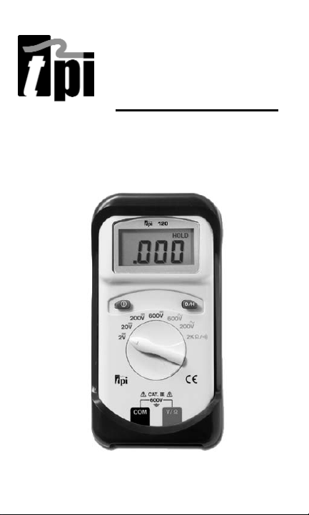
120
Digital Multimeter
Instruction Manual
Page 2

EC DECLARATION OF CONFORMITY
This is to certify that model 120 conforms to the
protection requirements of the council directive
89/336/EEC, in the approximation of laws of the
member states relating to Electromagnetic compatibility and 73/23/EEC, The Low Voltage Directive by
application of the following standards:
EN 50081-1 1992 Emissions Standard
EN 50082-1 1992 Immunity Standard
EN61010-1 1993 Safety Standard
EN61010-2-031 1995 Safety Standard
To ensure conformity with these standards, this
instrument must be operated in accordance with the
instructions and specifications given in this manual.
CAUTION:
Even though this instrument complies with the immunity standards, the accuracy can be affected by strong radio
emissions not covered in the above standards. Sources such
as hand held radio transceivers, radio and TV transmitters,
vehicle radios and cellular phones generate electromagnetic
radiation that could be induced into the test leads of this
instrument. Care should be taken to avoid such situations or
alternatively, check to make sure that the instrument is not
being influenced by these emissions.
2 3
Page 3
SAFETY CONSIDERATIONS
WARNING: Please follow manufacturers
test procedures whenever possible. Do not
attempt to measure unknown voltages or
components until a complete understanding
of the circuit is obtained.
GENERAL GUIDELINES
ALWAYS
• Test the 120 before using it to make sure it is operating
properly.
• Inspect test leads before using to make sure there are no
breaks or shorts.
• Double check all connections before testing.
• Have someone check on you periodically if working alone.
• Have a complete understanding of circuit being measured.
• Disconnect power to circuit, then connect test leads to the
120, then to circuit being measured.
NEVER
• Attempt to measure unknown high voltages.
• Attempt to measure current with the meter in parallel to the
circuit.
• Connect the test leads to a live circuit before setting up the
instrument.
• Touch any exposed metal part of the test lead assembly.
Page 4
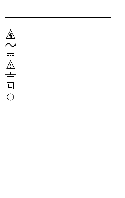
INTERNATIONAL SYMBOLS
CAUTION: RISK OF ELECTRIC SHOCK
AC (ALTERNATING CURRENT)
DC (DIRECT CURRENT)
REFER TO INSTRUCTION MANUAL
GROUND
DOUBLE INSULATION
ON/OFF, PUSH BUTTON SWITCH
Features and Benefits
Safety Meets CE and IEC 1010 requirements. UL Listed.
Large LCD Easy to read at all angles and the majority of light-
Data Hold Freeze readings on the display.
Rubber Boot Added protection when the instrument is dropped.
Versatile Use accessories like a carbon monoxide attachment
ing levels.
(120NB does not include boot.)
to expand the capabilities of the 120.
Page 5

SPECIFICATIONS
a. General Specifications
Power Supply 9 Volt Battery
Battery Life 560 hrs. Alkaline
Size (H x L x W) 33mm x 86mm x 187mm
Weight 340g (12 oz)
IEC 1010 Over Voltage:
CAT II - 1000V, CAT III - 600V
Pollution Degree 2
b. DCV
Range Resolution Accuracy Impedance
2V 0.001V ±0.5% of reading, 10MΩ
20V 0.01V ±2 digits
200V 0.1V
600V 0.1V
c. ACV (45Hz to 450Hz)
Range Resolution Accuracy Impedance
200V 0.1V ±1.2% of reading, 10MΩ
600V 1V ±3 digits
d. OHM (Resistance,ΩΩ)
Range Resolution Accuracy Overload Protection
2kΩ 0.001kΩ ±0. 5% of rdg, 600V DC or AC Peak
e. Continuity Buzzer
Test Voltage Threshold Overload Protection
2.5V <100Ω 600 V DC or Peak AC
*Warning: Test Leads: Use only correct type and overvoltage category rating.
(1.3” x 3.4” x 7.4”)
±1 digit
54
Page 6

MEASUREMENT TECHNIQUES
1. Controls and Functions:
Push Buttons
Turns the 120 on and off.
D/H Activates the Data Hold function.
Rotary Switch
V Used for measurement of DC Volts.
Select best range for the voltage to
be measured.
V Used for measurement of AC Volts.
Select best range for the voltage to
be measured.
ΩΩ
Input Jacks
COM Black test lead connection for all
V/
Used for measurement of
Resistance and Continuity.
functions.
ΩΩ
Red test lead connection for OHM,
Continuity Buzzer, DCV and ACV
functions.
Page 7

STEP BY STEP PROCEDURES
a.Measuring DC Volts
WARNING!
Do not attempt to make a voltage measurement of more than 600V or of a voltage level that
is unknown.
Instrument set-up:
FUNC BLACK RED MIN MAX
TEST LEAD TEST LEAD READING READING
DCV COM VΩ 0.001V 600V
Measurement Procedure:
1. Disconnect power to circuit to be meas-
ured.
2. Plug the black test lead into the COM input
jack.
3 Plug red test lead into V/
4. Set rotary switch on 120 to desired range
in DCV function depending on the voltage
to be measured.
5. Connect the test leads to the circuit to be
measured.
6. Reconnect power to the circuit to be meas-
ured.
7. Read the voltage on the 120.
Ω input jack.
76
Page 8

STEP BY STEP PROCEDURES
b.Measuring AC Volts
WARNING!
Do not attempt to make a voltage measurement of more than 600V or of a voltage level that
is unknown.
Instrument set-up:
FUNC BLACK RED MIN MAX
TEST LEAD TEST LEAD READING READING
ACV COM VΩ 0.001V 600V
Measurement Procedure:
1. Disconnect power to circuit to be measured.
2. Plug the black test lead into the COM input
jack.
3 Plug red test lead into V/ΩΩinput jack.
4. Set rotary switch on 120 to desired range
in ACV function depending on the voltage
to be measured.
5. Connect the test leads to the circuit to be
measured.
6. Reconnect power to the circuit to be
measured.
7. Read the voltage on the 120.
Page 9

STEP BY STEP PROCEDURES
c. Measuring Resistance
WARNING!
Do not attempt to make resistance measurements
with circuit energized. For best results, remove
resistor completely from circuit before attempting
to measure.
NOTE:
To make accurate low ohm measurements, short ends of test
leads together and record resistance reading. Deduct this
value from actual readings.
Instrument set-up:
FUNC BLACK RED MIN MAX
TEST LEAD TEST LEAD READING READING
OHM COM VΩ 1Ω 2.000kΩ
Measurement Procedure:
1. Disconnect power to the circuit to be measured.
2. Plug the black test lead into the COM input
jack.
3. Plug the red test lead into the V/ΩΩinput jack.
4. Set rotary switch on the 120 to 2kΩΩfunction
depending on the voltage to be measured.
5. Connect the test leads to the circuit to be
measured.
6. Read the resistance value on the 120.
98
Page 10

STEP BY STEP PROCEDURES: 10
d. Continuity Buzzer
WARNING!
Do not attempt to make continuity measurements
with circuit energized.
Instrument set-up:
FUNCTION BLACK TEST LEAD RED TEST
LEAD
OHM( ) COM VΩ
Measurement Procedure:
1. Disconnect power to the circuit to be measured.
2. Plug the black test lead into the COM input jack.
3. Plug the red test lead into the V/Ω input jack.
4. Set the rotary switch on the 120 to the
position.
5. Connect the test leads to the circuit to be measured.
6. Listen for the buzzer to confirm continuity.
e. Data Hold
Press the DATA-H button at any time on any func-
tion or range to freeze the reading on the LCD display. This function is very useful when measuring
in locations where the display is difficult to read.
Page 11

Standard Accessories Part No.
9V Battery A009
Test Lead Set A040
Rubber Boot (120 only) A121
Optional Accessories Part No.
Deluxe Test Lead Set SDK1C
Microamp Adapter A112
Temperature Adapter A301
Carbon Monoxide Accessories A701/A702/A711
Boot Hook A120
Soft Carrying Case A255
Carrying Case for multiple instruments A901
*These accessories have not been evaluated by UL and are
not considered as part of the UL Listing of this product.
MAINTENANCE
1. Battery Replacement: The 120 will display BAT when the
internal 9 Volt battery needs replacement. The battery is
replaced as follows:
a. Disconnect and remove all test leads from live circuits
and from 120.
b. Remove the 120 from its protective boot.
c. Remove the four screws from back of 120 housing.
d. Carefully pull apart front and rear instrument housing.
e. Remove old battery and replace it with new battery.
f. Reassemble instrument in reverse order from above.
2. Cleaning your 120
Use a mild detergent and slightly damp cloth to clean the
surfaces of 120.
1110
Page 12

The Value Leader
www.tpi-thevalueleader.com
TM
120 Instruction Manual
Test Products International, Inc.
9615 SW Allen Blvd
Beaverton, OR 97005-4814 USA
Ph: 503-520-9197 Fax: 503-520-1225
Test Product International Ltd.
342 Bronte Street South, Unit 9
Milton, Ontario L9T 5B7
Ph: 905-693-8558 Fax: 905-693-0888
Test Products International UK Ltd.
Longley House, East Park
Ph: +44 (0) 1293 561212 Fax: +44 (0) 1293 813465
Crawley, West Sussex RH10 6AP
Copyright © 2002, Test Products International, Inc
 Loading...