

Page 1
A795 Two-Color Thermal Receipt Printer
User Guide
Programming Supplement
A795-D100 PS Revision E 05/25/05
Includes TPG, Inc. LogoEZ
Made under one or more of the following U.S. patents:
4886381, 5579043, 5613787, 5651624, 5713678, 5752779, 5789916, 5800080, 5879090, 5887999, 5975776,
6027266, 6085973, 6089450, 6129465, 6155483, 6404452, 6486902, 6504331, 5749277, 6722754, 6739773,
6784909.
®
colorization information
Page 2
Federal Communications Commission (FCC) Radio Frequency Interference Statement Warning
Changes or modifications to this unit not expressly approved by the party responsible for compliance could void the user’s authority to operate the
equipment.
Note
This equipment has been tested and found to comply with the limits for a Class A digital device, pursuant to Part 15 of the FCC Rules. These limits are
designed to provide reasonable protection against harmful interference when the equipment is operated in a commercial environment. This equipment
generates, uses, and can radiate radio frequency energy and, if not installed and used in accordance with the instruction manual, may cause harmful
interference to radio communications. Operation of this equipment in a residential area is likely to cause harmful interference in which case the user will be
required to correct the interference at his own expense.
Information to the User
This equipment must be installed and used in strict accordance with the manufacturer’s instructions. However, there is no guarantee that interference to
radio communications will not occur in a particular commercial installation. If this equipment does cause interference, which can be determined by turning
the equipment off and on, the user is encouraged to contact TPG, Inc. immediately.
TPG, Inc. is not responsible for any radio or television interference caused by unauthorized modification of this equipment or the substitution or attachment of
connecting cables and equipment other than those specified by TPG, Inc. The correction of interferences caused by such unauthorized modification,
substitution or attachment will be the responsibility of the user.
In order to ensure compliance with the Product Safety, FCC and CE marking requirements, you must use the power supply, power cord, and interface
cable which are sold for use with this product or which meet the following parameters:
Power Supply
UL Listed (QQGQ), Class 2 power supply with SELV (Secondary Extra Low Voltage), non-energy hazard output, limited energy source, input rated 100240 Vac, 1.5/0.8 A, 50/60 Hz, output rated 24 Vdc, 2.3 A for 55 watt unit; 100-240 Vac, 2.0A, 50/60 Hz, output rate 24 Vdc, 3.125 A for 75 watt unit.
Use of this product with a power supply other than the TPG, Inc. power supply will require you to test the power supply and TPG, Inc. printer for FCC and
CE mark certification.
Communication Interface Cable
A shielded (360 degree) interface cable must be used with this product. The shield must be connected to the frame or earth ground connection or earth
ground reference at EACH end of the cable.
Use of a cable other than described here will require that you test the cable with the TPG, Inc. printer and your system for FCC and CE mark certification.
Power Cord
A UL listed, detachable power cord must be used. For applications where the power supply module may be mounted on the floor, a power cord with Type
SJT marking must be used. For applications outside the US, power cords which meet the particular country’s certification and application requirements
should be used.
Use of a power cord other than described here may result in a violation of safety certifications which are in force in the country of use.
Industry Canada (IC) Radio Frequency Interference Statement
This Class A digital apparatus meets all requirements of the Canadian Interference-Causing Equipment Regulations.
Cet appareil numérique de la classe A respecte toutes les exigences du Règlement sur le matériel brouilleur du Canada.
Voluntary Control Council for Interference (VCCI) Radio Frequency Interference Statement
This is a Class A product based on the standard of the Voluntary Control
Council for Interference by Information Technology Equipment (VCCI). If this
equipment is used in a domestic environment, radio disturbance may arise.
When such trouble occurs, the user may be required to take corrective actions.
Disclaimer
Information in this document is subject to change without notice. Consult your TPG, Inc. sales representative for information that is applicable and current.
TPG, Inc. reserves the right to improve products as new technology, components, software, and firmware become available.
No part of this document may be reproduced, transmitted, or translated in any form or by any means, electronic or mechanical, for any purpose without the
express written permission of TPG, Inc.
Copyright
Copyright © 2005 by TPG, Inc.
950 Danby Road, Ithaca, New York 14850, USA. All rights reserved. Printed in USA. Confidential, Unpublished. Property of TPG, Inc.
Trademarks
TPG, Inc.™ is a trademark of TPG, Inc. and its subsidiaries.
Microsoft, Windows NT are registered Trademarks of Microsoft Corporation in the U.S.A. and/or other countries.
Inside Out Networks, Inside Out, EPIC, and Edgeport are trademarks of Inside Out Networks.
All other trademarks and registered trademarks are the property of their respective holders.
Patents
Made under one or more of the following U.S. patents: 4886381, 5579043, 5613787, 5651624, 5713678, 5752779, 5789916, 5800080, 5879090, 5887999,
5975776, 6027266, 6085973, 6089450, 6129465, 6155483, 6404452, 6486902, 6504331, 5749277, 6722754, 6739773, 6784909.
Web Site
http://www.TPGprinters.com
Page 3

Revision E May 2005
Contents
A795 User Guide: Programming Supplement
Chapter 1: About this Supplement ................................................. 9
How to use this supplement ......................................................... 9
Where to find the basics ............................................................... 9
Where to find advanced technical information ............................ 9
Support ........................................................................................ 9
Chapter 2: Diagnostics and Configuration.................................... 11
Start-up Diagnostics .................................................................. 11
Runtime diagnostics .................................................................. 12
Remote diagnostics.................................................................... 12
Indicators ................................................................................... 14
Printer configuration.................................................................. 15
Configuring the printer..................................................................16
Communication interface ..............................................................17
RS-232C serial interface settings ....................................................17
Diagnostic modes .........................................................................18
Enable or disable data scope mode ................................................18
Enable or disable receipt test mode................................................19
Printer emulations.........................................................................19
Printer settings and functions ........................................................20
Select the emulation/software options sub-menu: ......................20
Select the hardware options sub-menu to set: .............................21
3
Contents
Chapter 3: Programming the Printer ............................................ 23
Overview of commands.............................................................. 23
Comparison to A793................................................................... 23
T wo-color commands (comparison A794 to A795) ..................... 24
Character appearance ................................................................ 26
Width specifications ......................................................................26
Standard..................................................................................26
Compressed .............................................................................26
Print zones ................................................................................. 26
Print zones for 80mm paper...........................................................26
Print zones for 82.5mm paper ........................................................27
Rotated printing commands ...................................................... 27
Emulation modes ....................................................................... 28
Print setup in emulation modes .....................................................28
Page 4

A795 User Guide: Programming Supplement
4
Contents
Chapter 4: Programming Commands ........................................ 29
Commands listed by function ................................................. 29
Printer actions ............................................................................. 29
Print and paper feed .................................................................... 30
Vertical and horizontal positioning ............................................... 30
T ext characteristics....................................................................... 31
Graphics ...................................................................................... 32
Status .......................................................................................... 33
Batch mode ............................................................................ 33
Real time ................................................................................ 33
Unsolicited status mode .......................................................... 33
Bar codes .................................................................................... 34
Page mode.................................................................................. 35
Macros ........................................................................................ 35
User data storage ......................................................................... 36
Flash download ....................................................................... 36
Command conventions............................................................ 37
Command descriptions............................................................ 38
Printer actions ............................................................................. 38
Clear printer............................................................................ 38
Perform full knife cut .............................................................. 38
Perform partial knife cut.......................................................... 39
Generate tone......................................................................... 39
Select peripheral device (for multi-drop) ................................. 39
Initialize printer....................................................................... 39
Select paper sensors to output paper-end signals..................... 40
Select sensors to stop printing ................................................. 40
Enable or disable panel button ................................................ 41
Generate pulse to open cash drawer ....................................... 41
Set current color ..................................................................... 42
Select cut mode and cut paper ................................................ 42
Set paper type (ColorPOS
Set interpretation of “Set current color” command ................... 44
Print test form......................................................................... 44
Print and paper feed .................................................................... 45
Print and feed paper one line .................................................. 45
Print and carriage return .......................................................... 45
Feed n dot rows ...................................................................... 45
Feed n print lines .................................................................... 45
Add n extra dot rows ............................................................... 46
Print........................................................................................ 46
Print and feed paper ............................................................... 47
Print and feed n lines .............................................................. 47
®
)...................................................... 43
Revision E May 2005
Page 5

Revision E May 2005
A795 User Guide: Programming Supplement
Vertical and horizontal positioning ............................................... 48
Horizontal tab ......................................................................... 48
Set horizontal and vertical minimum motion units ................... 48
Set column ............................................................................. 48
Set absolute starting position................................................... 49
Set vertical line spacing to 1/6 inch.......................................... 49
Set vertical line spacing ........................................................... 50
Set horizontal tab positions...................................................... 50
Set relative print position......................................................... 51
Select justification ................................................................... 52
Set left margin ........................................................................ 52
Set printing area width ............................................................ 53
T ext characteristics commands..................................................... 54
Select double-wide characters ................................................ 54
Select single-wide characters .................................................. 54
Select 90 degree counter-clockwise rotated print .................... 54
Select pitch (column width) .................................................... 55
Set right-side character spacing ............................................... 55
Select print mode ................................................................... 56
Select or cancel user-defined character set .............................. 56
Define user-defined character set ........................................... 57
Select or cancel underline mode ............................................. 57
Copy character set from ROM to RAM ...................................... 58
Cancel user-defined character................................................. 58
Select or cancel emphasized mode ......................................... 58
Select or cancel double-strike.................................................. 59
Select or cancel italic print....................................................... 59
Select international character code.......................................... 60
Select or cancel 90 degree clockwise rotated print .................. 60
Select international character set............................................. 61
Select or cancel upside-down print mode................................ 61
Select character size ............................................................... 62
Select or cancel white/black reverse print mode ...................... 63
Reverse color text mode (ColorPOS
T ext strike-through mode (ColorPOS
®
)....................................... 63
®
) ..................................... 64
Select superscript or subscript modes ...................................... 64
5
Contents
Page 6

A795 User Guide: Programming Supplement
6
Contents
Graphics ...................................................................................... 65
Download BMP logo .............................................................. 65
Select bit image mode.......................................................... 66
Print advanced raster graphics ............................................. 67
Select single-density graphics ............................................. 67
Select double-density graphics ............................................ 68
Select the current logo (ColorPOS
Define downloaded bit image (ColorPOS
Print downloaded bit image (ColorPOS
Print raster monochrome graphics (ColorPOS
Print raster color graphics (ColorPOS
Download logo image (ColorPOS
Apply shading to logo (ColorPOS
Merge watermark mode (ColorPOS
Monochrome shade mode (ColorPOS
Color shade mode (ColorPOS
Logo print with color plane swap (ColorPOS
Form and merge real time surround graphic (ColorPOS
Save graphics buffer as logo (ColorPOS
Background logo print mode (ColorPOS
Apply margin message mode (ColorPOS
Shade and store logo (ColorPOS
Logo print with knife cut ......................................................... 76
Set temporary max target speed.............................................. 76
Set LogoEZ
Set LogoEZ
Convert 6-dots/mm bitmap to 8-dots/mm bitmap ................ 81
Enable constant speed logos ............................................... 81
Status ........................................................................................ 82
Status command introduction ............................................... 82
Batch mode ........................................................................... 82
Transmit peripheral device status (RS-232C printers only) . 83
Request alternate status (A793 emulation only) .................. 83
Transmit paper sensor status ............................................... 84
Transmit printer ID ................................................................ 85
Transmit printer ID, remote diagnostics extension .............. 86
Transmit status ..................................................................... 88
Send printer software version............................................... 90
Real time commands ................................................................ 90
Preferred implementation ...................................................... 90
Alternate implementation ...................................................... 90
Rules for using real time commands ................................... 91
Moving data through the buffer ............................................. 91
Busy line and fault conditions .............................................. 91
Real time status transmission .............................................. 92
Real time request to printer .................................................. 93
Real time printer status transmission .................................. 93
Real time commands disable ............................................... 94
®
) .................................... 68
®
)........................... 69
®
) ............................. 70
®
) .................. 70
®
) ............................... 71
®
)....................................... 71
®
) .......................................... 72
®
)....................................... 72
®
) ................................... 73
®
) ................................................ 73
®
) .......................... 73
®
) ......... 74
®
) ................................. 74
®
) ................................ 75
®
) ............................... 75
®
) ............................................ 75
®
colorization ...................................................... 77
®
attribute mapping ............................................ 80
Revision E May 2005
Page 7

Revision E May 2005
A795 User Guide: Programming Supplement
Unsolicited status mode ............................................................ 95
Select or cancel unsolicited status mode (USM) ................ 95
Recognizing data from the printer ......................................... 97
Bar codes .................................................................................. 98
Select printing position of HRI characters............................ 98
Select pitch of HRI characters .............................................. 98
Select bar code height.......................................................... 98
Print bar code........................................................................ 99
Select PDF 417 parameters ............................................... 101
Select bar code width ......................................................... 102
Page mode .............................................................................. 103
Print and return to standard mode...................................... 103
Cancel print data in page mode.......................................... 103
Print data in page mode ...................................................... 103
Select page mode ............................................................... 104
Select standard mode ......................................................... 104
Select print direction in page mode.................................... 105
Set print area in page mode ............................................... 106
Set absolute vertical print position in page mode .............. 107
Set relative vertical print position in page mode................. 107
Macros ..................................................................................... 108
Select or cancel macro definition ....................................... 108
Execute macro .................................................................... 108
User data storage .................................................................... 109
Write to user data storage .................................................. 109
Read from user data storage .............................................. 109
Read from non-volatile memory .......................................... 109
Write to non-volatile memory (NVRAM) ............................. 109
Select memory type (SRAM/flash) ......................................110
Flash memory user sectors allocation ................................110
Erase user flash sector ........................................................ 111
User storage status (ColorPOS
®
) ........................................112
Flash download......................................................................... 113
Switch to flash download mode ...........................................113
Return boot sector firmware part number ............................ 114
Return segment number status of flash memory................114
Select flash memory sector to download ............................ 114
Get firmware CRC ................................................................114
Return microprocessor CRC................................................ 115
Erase all flash contents except boot sector ....................... 115
Return main program flash CRC..........................................115
Erase selected flash sector ................................................. 115
Download to active flash sector ...........................................116
Download paper type description (ColorPOS
Return paper type description (ColorPOS
®
) ...................116
®
) ........................ 117
Reset firmware ..................................................................... 117
7
Contents
Page 8

A795 User Guide: Programming Supplement
8
Contents
Appendix A:
Commands listed by hexadecimal code ..............................119
By command code .................................................................119
Appendix B:
Resident Character Sets.....................................................125
Character sets .....................................................................125
Code page 437 (US) ................................................................ 125
Code page 737 (Greek) ........................................................... 126
Code page 850 (Multilingual)................................................... 127
Code page 852 (Slavic) ........................................................... 128
Code page 858 (with Eurosymbol) .......................................... 129
Code page 860 (Portuguese) .................................................. 130
Code page 862 (Hebrew) ......................................................... 131
Code page 863 (French Canadian) ......................................... 132
Code page 865 (Nordic)........................................................... 133
Code page 866 (Cyrillic) .......................................................... 134
Code page 1252 (Windows Latin 1) ........................................ 135
Revision E May 2005
Page 9

Revision E May 2005
A795 User Guide: Programming Supplement
Chapter 1: About this Supplement
Chapter 1: About this Supplement
How to use this supplement
This is a supplemental guide providing programming information on TPG, Inc.’s A795 printer. It is written for techsavvy users who are interested in customizing or adjusting printer functionality and is meant to be used in
conjunction with the A795 ColorPOS
If you experience any difficulties during the programming process or feel unsure of adjustments you have made,
contact your TPG, Inc. representative for further assistance.
Where to find the basics
®
Two-Color Thermal Receipt Printer: User Guide.
9
If you are looking for information on setup or basic operation, refer to the A795 ColorPOS® User Guide. This
supplemental guide assumes that you have the A795 ColorPOS
familiar with the printer.
®
User Guide handy for reference or are already
Where to find advanced technical information
This guide contains the most complete information available on programming the printer. If you cannot find what you
need here or would like further guidance on how to program the printer, contact an TPG, Inc. representative for
assistance.
®
If you are having problems with the physical operation of the printer, the A795 ColorPOS
in-depth information on diagnostics and service. The A795 ColorPOS
service technicians who have been certified by TPG, Inc. to perform advanced procedures.
®
Service Guide is available to qualified
Service Guide, provides
Support
For more advanced procedures and troubleshooting, you may need to refer to the printer’s service guide or speak to
an TPG, Inc. technical professional. Your representative is able to provide you with necessary information.
For on-line service, refer to the Web site at www.TPGprinters.com or e-mail to: [email protected].
Page 10

A795 User Guide: Programming Supplement
10
Chapter 1: About this Supplement
Revision E May 2005
This page intentionally lef t blank.
Page 11

Revision E May 2005
Revision E May 2005
A795 User Guide: Programming Supplement
Chapter 2: Diagnostics and Configuration
Chapter 2: Diagnostics and Configuration
The A795 printer performs a number of diagnostics that provide useful information about the operating status of the
printer. The following diagnostic tests are available. See pages 11 and 12 for more information.
11
• Start-up diagnostics
Performed during the printer’s start-up cycle.
• Runtime diagnostics
Performed during normal printer operation.
• Remote diagnostics
Maintained during normal operation and
reported in the print test.
• The printer can be configured with the following
settings and functions through the configuration menu
that is printed on the receipt. For more information on
configuring the printer, see “Printer configuration” on
page 15.
Communication interfaces
Diagnostic modes
RS-232C settings
Printer emulations/software options
Hardware options
Start-up Diagnostics
When the printer receives power or performs a hardware reset, it automatically performs the startup
diagnostics (also known as level 0 diagnostics) during the start-up cycle. The following diagnostics
are performed:
• Turn off motors
• Perform boot CRC check of the firmware ROM, test
external SRAM, test EEPROM, and test main program
CRC
Failure causes Start-up Diagnostics to stop; the
printer beeps and the LED flashes a set number of
times, indicating the nature of the failure. The
table in the “Indicators” section (page 14)
describes the specific tone and LED sequences.
• Check if paper is present
• Return the knife to the home position
Failure causes a fault condition. The table in
the “Indicators” section (page 14) describes
the specific tone and LED sequences.
• Check if receipt cover is closed
Failure does not interrupt the start-up cycle.
When the start-up diagnostics are complete, the printer
makes a two-tone beep (low then high frequency), the
paper feed button is enabled, and the printer is ready for
normal operation.
If the printer has not been turned on before, or a new
EEPROM has been installed, the default values for the
printer functions will be loaded into the EEPROM
during start-up diagnostics.
Page 12

A795 User Guide: Programming Supplement
12
Chapter 2: Diagnostics and Configuration
Runtime diagnostics
Runtime diagnostics (sometimes called level 2 diagnostics) run during normal printer operation.
When the following conditions occur, the printer automatically turns off the appropriate motors and
disables printing to prevent damage to the printer:
Revision E May 2005
• Paper out
• Receipt cover open
• Knife unable to home
• Printhead too hot
• Voltages out of range
The LED on the operator panel will signal when these
conditions occur as well as indicate what state or mode the
printer is in.
Remote diagnostics
Remote diagnostics (sometimes called level 3 diagnostics) keeps track of the following tallies and
prints them on the receipt during the print test. See the sample test printout on the next page. These
tallies can be used to determine the printer’s state of health.
• Model number
• Serial number
• CRC number
• Number of lines printed
• Number of knife cuts
• Number of hours the printer has been on
• Number of flash cycles
• Number of cutter jams
• Number of times the cover is opened
• Maximum temperature reached
(See tallies note on the following page.)
Page 13

Revision E May 2005
A795 User Guide: Programming Supplement
Chapter 2: Diagnostics and Configuration
13
*** A795 – Diagnostics Form ***
Model number : A795-2119
Serial number : A012251287
Boot Firmware
Revision : V1.02
CRC : 76EB
P/N : 189-1076076A
Flash Firmware
Revision : V1.13
CRC : AB62
P/N : 189-7950290A
H/W parameters
Flash Memoriy Size : 2 Mbytes
Flash Logos/Fonts : 1024 kbytes
Flash User Storage : 0 kbytes
SRAM Size : 256 kbytes
Head setting : D
Paper Type setting : Type 5, Version 0
Color Density Adj : 100%
Print Density (Mono) : 100%
Max Speed : 100 mm/sec
Paper Width : 80 mm
Max Power : 55 W
Knife : Enabled
Partial Cut : 135 steps
Paper Low Sensor : Disabled
Comm. Interface
RX Buffer Size : 4096
Interface type : RS232/USB
Parameters
Baud Rate : 115200
Data Bits : 8
Stop Bit : 1
Parity : NONE
Flow Control : DTR/DSR
Reception Errors : Ignore
Alternate DTR/DSR : Disabled
USB Driver Type : RS232 Emulation
Resident Code Pages : 437, 850, 852, 858
860, 863, 865, 866
1252, 862, 737
Available Paper Types : 00.00 01.00 05.00
01.90 01.92 01.93
Logo(s) defined : Yes
User Char(s) defined : NO
**************************************
**************************************
Select a sub-menu :
– EXIT
– Print Current Configuration -> 2 clicks
– Set Communication Interface -> 3 clicks
– Set Diagnostics Modes -> 4 clicks
– Set Emulation/Software Options -> 5 clicks
– Set Hardware Options
– Set Paper Type
Enter code, then hold Button DOWN
at least 1 second to validate
MAIN MENU
-
> 1 click
-
> 6 clicks
-
> 7 clicks
Paper type can be changed in the configuration menu.
Paper types and grades available:
Type 0 - Monochrome grades
Kanzaki P-310
Type 1 - Two-color grades
Kanzaki P-310 RB (Red/Black)
Type 4 - Two-color grades
Kanzaki P-320 BB (Blue/Black)
Type 5 - Two-color grades
Kanzaki P-320 RB (Red/Black)
See “printer configuration” section for more information.
When the printer is configured for USB and the
native USB solution driver is used, this location will
show either: “USB Driver Type: TPG , Inc.” or “USB
Driver Type: Printer Class”.
If the RS-232C, USB emulation solution driver is
used, nothing is printed here. See User Guide,
Appendix A.
To enter Printer Config Menu :
1) Flip DIP switch #1 down
2) Reset the printer, while holding
the Paper Feed button down
Print test and configuration menu samples will vary per model or printer
configuration. (Shown approximately 60% of size.)
For more information about See this section
Accessing the remote diagnostic tallies “Command descriptions” in Chapter 4: Programming commands
(Status commands: Transmit printer ID, remote diagnostics extension,
Hexadecimal 1D 49 40 n)
Page 14

A795 User Guide: Programming Supplement
14
Chapter 2: Diagnostics and Configuration
Revision E May 2005
Indicators
The printer communicates various conditions both visually, with the green LED or audibly,
with a series of tones or beeps. The following table lists these indicators.
Indicator Sequence Condition
L ED Continuous, flashing quickly Paper out
Cover off
Knife unable to home
L ED Continuous, flashing slowly Paper is low
(if paper low sensor is installed)
Printhead too hot
Voltages out of range
T o ne Two-tone beep Start-up diagnostics completed successfully
(low frequency, high frequency)
L ED Single beep Boot CRC test failure
and T one Single LED flash
L ED Double beep SRAM test failure
and T one Double LED flash
L ED Triple beep EEPROM test failure
and T one Triple LED flash
L E D Four beeps Dynamic memory initialization failure
and T one Four LED flash
L E D Two-T one beep Main program CRC test failure
and T one (high frequency, low frequency) O r
Continuous flashing of LED DIP switch is in on position indicating
flash download mode
The printer is also able to communicate its status to the host application if the application has been programmed to
receive this information.
For more information about See this section
Error conditions and “ Troubleshooting the
correcting them printer” on page 30,
Chapter 4: Using the
Printer, in the A795 User
Guide
For more information about See t his section
Communication of printer “Command descriptions”
status to the host application in Chapter 4: Programming
commands, page 38
Page 15

Revision E May 2005
A795 User Guide: Programming Supplement
Chapter 2: Diagnostics and Configuration
Printer configuration
Printers are shipped with all the functions and parameters preset at the factory. Settings for
various printer parameters can be changed. This menu is printed on the receipt and scrolls
through instructions for selecting and changing any of the functions or parameters.
Note: When changing the paper type you will either need to send the “Set paper type”
(1D 81 mn) command or make a selection in the configuration menu. See pages 16
and 43.
Caution: Be extremely careful changing any of the printer settings to avoid inadvertently
changing other settings that might affect the performance of the printer.
15
The following functions and parameters can be changed
in the scrolling configuration menu (except as noted):
• Communication Interface
RS-232C serial interface (9-pin)
RS-232C serial interface (25-pin)
Universal serial bus (USB)
• RS-232C serial interface settings
Baud rate
Data bits (can not be changed)
Stop bits (can not be changed)
Parity (can not be changed)
Hardware (DTR/DSR) or software (XON/XOFF)
flow control
Data reception errors
Alternate DTR/DSR
• Diagnostic Modes
Normal
Datascope
Receipt test
• Printer Emulations
A795 native mode
A794 emulation
A793 emulation
LEGACY emulation
• Printer settings and functions
Emulation/Software options submenu
Printer ID mode
Default lines per inch
Carriage return usage
Default font
Font size
Hardware options submenu
Color density
Monochrome print density
Power supply wattage (max power)
Knife option
Partial cut distance
Paper low sensor
Paper width
Printhead setting
For more information about Se e t his s ection
Using the configuration menu “Configuring the printer”
to configure the printer on page 16.
Page 16
A795 User Guide: Programming Supplement
16
Chapter 2: Diagnostics and Configuration
Configuring the printer
The configuration menu allows you to select functions or change various settings for the
printer. Instructions printed on the receipt guide you through the processes.
Caution: Be extremely careful changing any of the printer settings to avoid
changing other settings that might affect the performance of the printer.
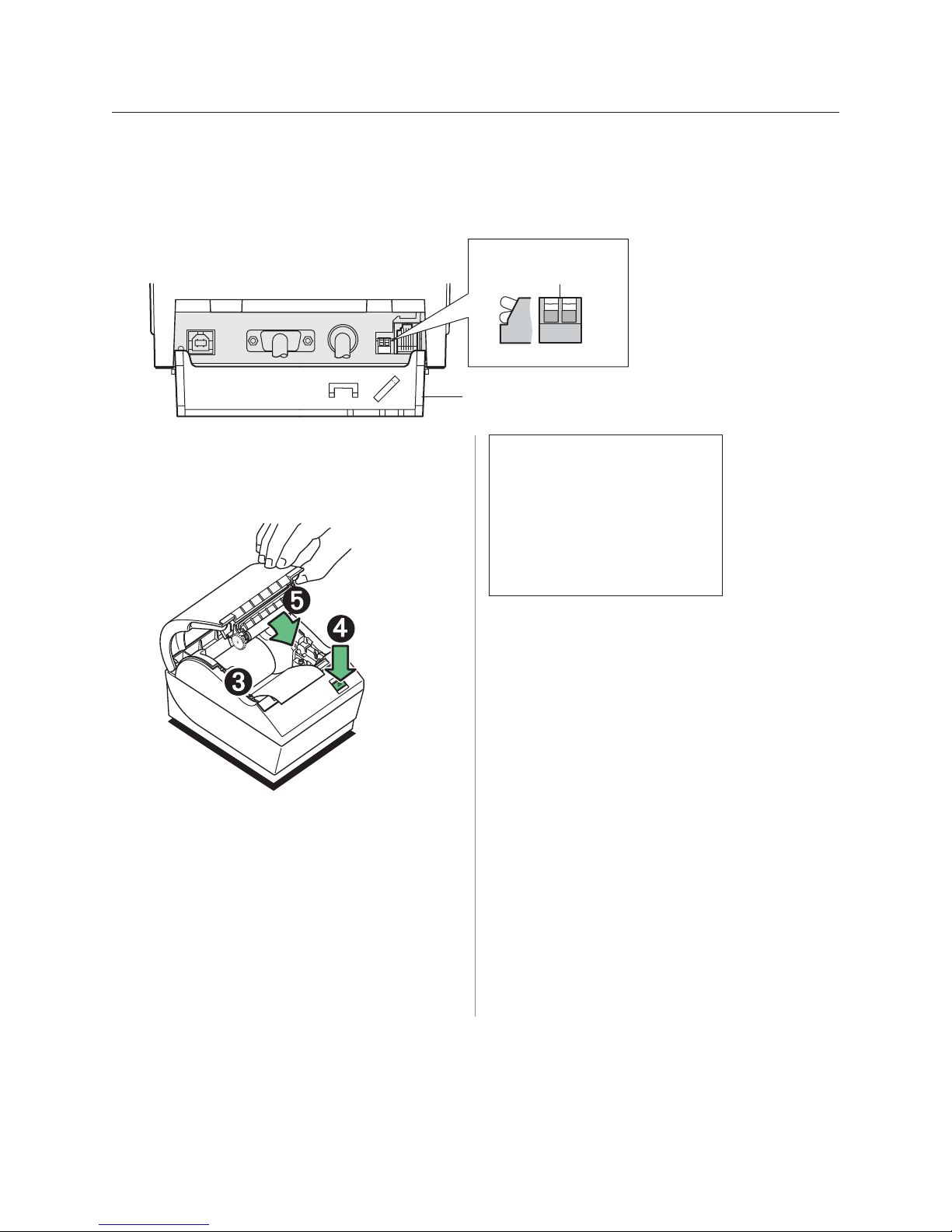
Switch 1 & 2 are
shown in the
normal OFF position
Off
On
Connector
Cover Open
121212
DIP Switches
Revision E May 2005
1 Open the connector cover.
2 Set DIP Switch 1 to ON position (down). DIP Switch
2 should be in the OFF position (up).
3 Make sure receipt paper is loaded in the printer
before proceeding. (For loading instructions, see the
A795 User Guide, page 14.)
4 Cycle DIP switch 2 down (reset ON position), then
up (normal OFF position).
- or Press and hold the paper feed button (4) while
closing the receipt cover (5), continually holding the
paper feed button until the configuration printout
begins.
• The printer beeps, prints the diagnostics form and
the configuration main menu.
*********
MAIN MENU
**********
*******************************
Select a sub-menu :
- EXIT -> 1 click
- Print Current Configuration -> 2 clicks
- Set Communication Interface -> 3 clicks
- Set Diagnostics Modes -> 4 clicks
- Set Emulation/Software Options -> 5 clicks
- Set Hardware Options -> 9 clicks
Enter code, than hold Button DOWN
at least 1 second to validate
• The printer pauses and waits for a main menu
selection to be made; short clicks are used, except
when answering “Yes” or validating selection (see
sample printout).
5 To communicate with the printer, you will press the
paper feed button using either short or long clicks.
Use a long click (more than one second) for “yes” and
a short click for a “no.” Follow the printed instructions
to make selections.
6 Continue through your menu selections until you are
asked, “Save New Parameters?”. Select “Yes” or “No.”
a If you wish to save, select “Yes,” then return DIP
switch 1 to the OFF Postion (up).
b. Open the receipt cover.
Press and hold the paper feed button while closing
the receipt cover.
• The diagnostic printout verifies your new
settings.
7 If you would like to continue configuring the printer,
select “No.” The printer then returns to the
configuration menu, where you can set parameters
again.
Page 17

Revision E May 2005
A795 User Guide: Programming Supplement
Chapter 2: Diagnostics and Configuration
Communication interface
To change the communication interface settings, enter the configuration menu, select “Set
Communication Interface” from the main menu and answer “Yes” to “SET INTERFACE TYPE?”
printed on the receipt.
Caution: Be extremely careful changing any of the printer settings to avoid inadvertently
changing other settings that might affect the performance of the printer.
17
Press the paper feed button as instructed to select the
communication interface you want.
Note: For USB installation, see Appendix A, USB Driver Installation, page 39.
• Communication interface
• RS-232C interface: 1 click
• USB: Auto when no
RS-232C activity
RS-232C serial interface settings
To change the RS-232C serial interface settings, enter the configuration menu, select “Set
Communication Interface” from the main menu and answer “No” to “SET INTERFACE TYPE?”
printed on the receipt. This will take you to the instructions for selecting the RS-232C settings.
Caution: Be extremely careful changing any of the printer settings to avoid inadvertently
changing other settings that might affect the performance of the printer.
Press the paper feed button as instructed on the configuration menu to select the
RS-232C settings you want to change.
• Baud rate
115200 baud
57600 baud
38400 baud
19200 baud
9600 baud
4800 baud
2400 baud
1200 baud
• Number of data bits (can not be changed)
• Stop bits (can not be changed)
• Parity (can not be changed)
• Hardware flow control
Software (XON/XOFF)
Hardware (DTR/DSR)
• Data reception errors
Ignore errors
Print “?”
• Alternate DTR/DSR
Enabled
Disabled
Note: Press the paper feed button for at least one
second to validate the selection.
For more information about See this section
Setting the RS-232C Serial “Configuring the printer”
interface settings on page 16.
Page 18
A795 User Guide: Programming Supplement
18
Chapter 2: Diagnostics and Configuration
Diagnostic modes
To change the diagnostic modes enter the configuration
menu, select “Set Diagnostic Modes” from the main menu
and select one of the following modes:
• Normal: normal operating mode of the printer.
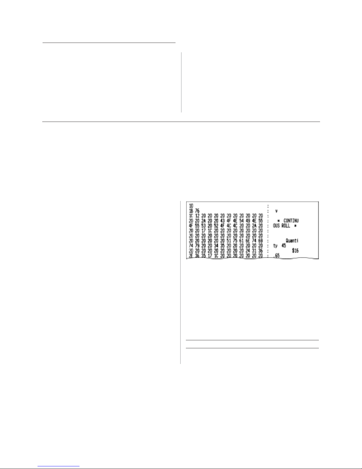
• Datascope: the receipt printer prints incoming
commands and data in hexadecimal format to help
troubleshoot communication problems.
• Receipt test: the receipt printer prints two code
pages to verify proper printing of the receipt.
Caution: Be extremely careful changing any of the
printer settings to avoid inadvertently changing other
settings that might affect the performance of the printer.
See Configuring the printer,” page 16 for instructions on
how to enter the configuration menu.
Enable or disable data scope mode
The data scope mode test prints a hexadecimal dump of all data sent to the printer: “1” prints
as hexadecimal 31, “A” as hexadecimal 41 and so on. This helps troubleshoot communication
problems and runs during a normal application (after being enabled through printer configuration).
Note: Data scope mode is usually considered a level 1 diagnostic test.
Data scope mode is enabled and disabled by selecting the “Diagnostic Modes” sub-menu of the
configuration menu.
Revision E May 2005
Press the paper feed button as instructed on the
“Diagnostic Modes Menu” to enable or disable the data
scope mode test.
• Off, normal mode (Data scope mode disabled)
• Data scope mode (enabled)
Note: Press the paper feed button for at least one second
to validate the selection.
T o run the data scope mode:
1 After you have enabled the data scope mode, exit the
configuration menu.
2 Run a transaction from the host computer.
All commands and data sent from the host computer
will be printed as hexadecimal characters as shown in
the illustration.
T o exit the data scope mode:
1 Enter the configuration menu again.
See “Configuring the printer,” page 16.
2 Disable the data scope mode.
3 Exit the configuration menu.
The printer is on-line and can communicate normally
with the host computer.
For more information about See this section
Enabling the data scope “Configuring the printer”
mode on page 16.
Page 19

Revision E May 2005
A795 User Guide: Programming Supplement
Chapter 2: Diagnostics and Configuration
Enable or disable receipt test mode
The receipt test mode verifies proper receipt printing. Receipt test is enabled and disabled by
selecting the “Diagnostic Modes” sub-menu of the configuration menu. See “Configuring the
printer”, page 16 for instructions on how to enter the configuration menu.
19
T o run the Receipt test mode:
1 Enable the receipt test mode in the configuration
menu.
2 Exit the configuration menu.
3 Push the paper feed button. The receipt station
prints two code pages and cuts the receipt.
4 To repeat this test, push the paper feed button again.
T o exit the receipt test mode:
1 Enter the configuration menu again. (See
“Configuring the printer”, page 16.)
2 Disable the receipt test mode.
3 Exit the configuration menu.
The printer is on-line and can again communicate
normally with the host computer.
Printer emulations
To change the printer emulations settings, enter the configuration menu, select “Emulation/
Software Options” from the main menu and answer “Yes” to “Set the printer emulations?” printed
on the receipt. This will take you to the instructions for setting the printer emulation.
Caution: Be extremely careful changing any of the printer settings to avoid inadvertently changing
other settings that might affect the performance of the printer.
Press the paper feed button as instructed to select the
printer emulation you want.
• A795 native mode
• A794 emulation
• A793 emulation
• LEGACY emulation
Note: The A793, A794 and Application Compatible
Escape Command emulations do not recognize the
ColorPOS ® commands.
Note: Press the paper feed button for at least one
second to validate the selection.
For more information about See this section
Setting the printer emulation “Configuring the Printer”,
page 16
Page 20

A795 User Guide: Programming Supplement
20
Chapter 2: Diagnostics and Configuration
Printer settings and functions
To change the printer settings and functions, enter the configuration menu, select the submenu from the main menu and answer the questions printed on the receipt until you come to
the instructions for selecting the printer settings.
Caution: Be extremely careful changing any of the printer settings to avoid inadvertently
changing other settings that might affect the performance of the printer.
Press the paper feed button as instructed to select the printer settings you want.
Select the emulation/software options sub-menu to set:
Revision E May 2005
• Printer ID mode
This function is used to determine what printer ID
value is returned in response to a Transmit printer ID
command (1D 49 n) when the printer is in A794
emulation mode. The printer can be configured to send
back the ID of the A795, A794, A793 or Application
Compatible Escape Command systems.
• Default lines per inch
This function allows you to set the default for lines per
inch to:
• 8.13 lines per inch
• 7.52 lines per inch
• 6.77 lines per inch
• 6.00 lines per inch
• Carriage return usage
This function allows the printer to ignore or use the
carriage return (hexadecimal 0D) command depending
on the application. Some applications expect the
command to be ignored while others use the command
as a print command.
• Default font
Sets the default for monochrome, two-color, and
LEGACY emulations.
• Font size
Allows user to set font size for the emulation being
used.
Page 21

Revision E May 2005
Select the hardware options sub-menu to set:
• Printhead setting
This setting is the printhead energy rating and
must match the rating marked on the front right of
the thermal mechanism in the printer. Whenever a
new thermal mechanism is installed, this setting
must match the indicated energy rating on the
mechanism. (See A795 Service manual for
replacing the thermal mechanism.)
• Paper Type Name
Sets the printer to optimum performance for paper
being used. This can also be done through the
command 1D81 m n. See the following chapter for
command usage.
A vailable paper types may vary. Currently there are
4 types:
0 = monochrome, Kanzaki P310
1 = two-color, Kanzaki P310RB
4 = two-color, Kanzaki P320BB
5 = two-color, Kanzaki P320RB
(See page 36 in User Guide for available paper
manufacturers.)
• Color density
Adjusts printhead energy level to darken color
printing or adjust for paper variations. When printer
prints high-density color print lines (text or
graphics), it automatically slows down. Factory
setting is 100%.
CAUTION: Choose a color density setting no higher
than necessary to achieve acceptable color print
density. Failure to observe this rule may result in a
printer service call and may void the printer warranty.
Running at a higher energy level will reduce the
printhead life. Consult your TPG, Inc. technical
support specialist if you have questions.
A795 User Guide: Programming Supplement
Chapter 2: Diagnostics and Configuration
• Print density (monochrome papers only)
Adjusts printhead energy level to darken printout
or adjust for paper variations. When printer prints
high-density print lines (text or graphics), it
automatically slows down. Factory setting is
100%.
CAUTION: Choose a print density setting no higher
than necessary to achieve acceptable print density.
Failure to observe this rule may result in a printer
service call and may void the printer warranty.
Running at a higher energy level will reduce the
printhead life. Consult your TPG, Inc. technical
support specialist if you have questions.
• Power supply wattage (Max power)
You can choose between a 55-watt or 75-watt power
supply. This matches the wattage of the printer to the
power supply.
55-watt power supply (standard)
75-watt power supply (Enables printer to optimize
speed at higher dot coverage.)
• Knife option
This should only be changed if the knife is removed or
you do not want to cut the paper.
• Partial cut distance
Allows the user to set the distance that the knife will
cut across a receipt in 5 step increments between 110-
160.
• Paper low sensor
Senses when the paper roll is getting low on paper.
See troubleshooting section: “Receipt paper is low” in
the A795 User Guide.
• Paper width
Allows the user to set the printer for 58mm, 80mm or
82.5mm paper width.
21
For more information about See this section
Setting the printer functions “Configuring the printer”
and settings (See page 16.)
Page 22

A795 User Guide: Programming Supplement
22
Chapter 2: Diagnostics and Configuration
Revision E May 2005
This page intentionally lef t blank.
Page 23

Revision E May 2005
A795 User Guide: Programming Supplement
Chapter 3: Programming the Printer
Chapter 3: Programming the Printer
Overview of commands
Commands control all operations and functions of the printer. This includes selecting the size
and placement of characters and graphics on the receipt to feeding and cutting the paper. The
programming commands have been organized, in order of hexadecimal code within functional
groups. For this reason, “related” commands may not be listed adjacent to one another.
23
The operation of various printers may be emulated by
the commands, including the following:
• A793
• A794
• A795 native mode
• LEGACY
Any of the commands may be used in any combination
to program a host computer to communicate with the
printer (unless otherwise noted).
Some commands listed and described here may not be
implemented and are identified as “not implemented.” If
received, they are ignored and not sent to the print buffer
as data.
Any nonlegal commands have their parameter sent to the
print buffer as data.
Comparison to A793
The following table details the list of commands whose behavior differs between the
A793, A794, and A795 because of the physical differences of a 6 dots/mm head (A793) versus
an 8 dots/mm head (A794 and A795).
Command Description Difference between previous product
and new product emulation mode.
15 n Feed n dot rows This command will move the paper on the receipt in
n/203 inch steps instead of n/152 inch steps.
16 n Add n extra dot rows The dot rows will be measured in n/203 inches versus
n/152 inches.
1B 20 n Set right-side character spacing This command sets the right side spacing to “n” horizontal
1B 24 n1 n2 Set absolute starting position For graphics commands, the position is scaled to best
1B 26 s c1 c2 n1 d1...nn dn] Define user-defined character set Since the dots on the A795 printhead are smaller , user
1B 2A m n1 n2 d1...dn Select bit image mode In A793 emulation mode, graphics are scaled to best
1B 33 n Set line spacing This command uses n in terms of n/360 inches. Since the
continued...
motion units. By default, these units are in terms of 1/203
inches versus 1/152 inches.
match A793. In text mode, the equivalent character
position is calculated.
defined characters that were used on the previous printers
will appear smaller on the A794 printer .
match the size of the graphic in the A793 printer .
A793 had a fundamental step of 1/152 inch and the A795
has a fundamental step of 1/203 inch, the actual line
spacing will not exactly match the requested spacing.
Page 24

A795 User Guide: Programming Supplement
24
Chapter 3: Programming the Printer
Command Description Difference between previous product
and new product emulation mode.
1B 4A n Print and feed paper This command uses n in terms of n/360 inches. Since the
A793 had a fundamental step of 1/152 inch and the A795
has a fundamental step of 1/203 inch, the actual line
spacing will not exactly match the requested spacing.
1B 59 n1 n2 d1...dn Select double-density graphics In A793 emulation mode, the printer scales the graphics
to provide the best match.
1B 5C n1 n2 Set relative print position The parameter to this command is in units of dots.
However, the command moves and aligns to character
positions. In A793 emulation mode, this command
calculates how many character positions to move
based on the A793 character width in dot s (10)
versus the A795 (13).
1B 61 n Select justification This command does true dot resolution alignment for
centering versus character-aligned centering.
1D 2A n1 n2 d1...dn] Define downloaded bit image In A793 emulation mode, this command scales the
incoming data to provide a best match to the size of
the image as it printed on A793.
Revision E May 2005
1D 2F m Print downloaded bit image In A793 emulation mode, this command scales the
incoming data to provide a best match to the size of
the image as it printed on A793.
Two-color commands (comparison A794 to A795)
The following table details the list of commands that have been added for two-color ColorPOS
functionality (ColorPOS® commands, 1D 81 through 1D 97 are in bold) or existing commands
that have been altered by the addition of two-color capacity.
TPG, Inc. ColorPOS® two-color and color interpreted commands
Hexadecimal ASCII Description
1B 72 m ESC r m Set current color
1D A0 nl nh 1 D GS Set temporary maximum target speed
1D 23 n GS # n Select current logo
1D 42 n GS B n Select or cancel white/black reverse print mode
1D 2A n1 n2 d1 – dm GS * n1 n2 d1 – dm Define downloaded bit image
1D 2F m GS / m Print downloaded bit image
®
1D 81 m n GS 0x81 m n Set paper type
1D 82 n1– n72/n80 GS 0x82 n1– n72/n80 Print raster monochrome graphics
1D 83 n1– n144/n160 GS 0x83 n1– n144/n160 Print raster color graphics
Page 25

Revision E May 2005
TPG, Inc. ColorPOS® two-color and color interpreted commands continued
Hexadecimal ASCII Description
1D 84 n m n1 n2 d1 dx GS 0x84 n m n1 n2 d1 dx Download logo image
1D 85 m n GS 0x85 m n Reverse color text mode (two-color)
1D 86 m GS 0x86 m Monochrome shade mode
1D 87 m GS 0x87 m Color shade mode
1D 89 n m GS 0x89 n m Logo print with color plane swap
1D 8B n m o GS 0x8B n m o Apply shading to logo
1D 8C n m GS 0x8C n m Merge watermark mode
1D 8D n m GS 0x8D n m Text strike through mode
1D 8E m nL nH d1...dn GS 0x8E m nL nH d1...dn Download paper type description
A795 User Guide: Programming Supplement
Chapter 3: Programming the Printer
25
1D8F m GS 0x8F m Return paper type description
1D 90 m x y o p q GS 0x8A m x y o p q Form and print real time surround graphic
1D 91 n GS 0x91 n Save graphics buffer as logo
1D 92 n GS 0x92 n Background logo print mode
1D 97 m n GS 0x87 m n User storage status
1D 99 l m n o U S Apply margin message mode
1D 9A n m o GS 0x9A n m o Shade and store logo
1D 9B m n G S Logo print with knife cut
1F 03 16 05 n U S Set interpretation of “Set current color” command
TPG, Inc. LogoEZ® colorization commands
Hexadecimal ASCII Description
1F 03 16 f m n o p q US ETX SYN Set LogoEZ® surround graphics
1F 03 16 f s p/r t US ETX SYN f s p/r t Set colorization
1F 03 17 a m s US ETX ETB a m s Set attribute mapping
Note: The new TPG, Inc. LogoEZ ® colorization utility provides you a fast and easy way to get basic two-color and
logos onto your receipt without having to enter commands. Check out the TPG, Inc. Website at:
www.TPGprinters.com.
Page 26

A795 User Guide: Programming Supplement
26
Chapter 3: Programming the Printer
Character appearance
The appearance of text can be changed using the following print modes:
Revision E May 2005
• Standard
• Compressed
• Double-high
• Double-wide
• Upside-down
• Rotated
• Underlined
Width specifications
Standard
• Characters per inch: 15.6
• Characters per line: 44
• Cell size: 13 X 24 dots
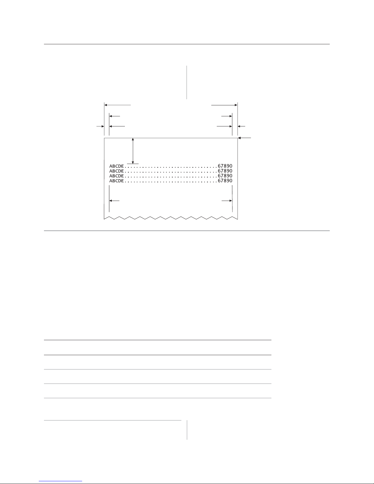
Print zones
Print zones for 80mm paper
Specifications of print zone for 80mm paper:
• 576 dots (addressable) @ 8 dots/mm,
centered on 80mm
• Standard mode: minimum margins:
2.0mm (.079 inches)
• Bold
• Reverse
• Italic
• Strike-through
• Scaled
• Shading
Compressed
• Characters per inch: 20.3
• Characters per line: 56
• Cell size: 10 X 24 dots
• Top margin to manual tear-off:
17.8mm (0.70 inches)
• Top mar gin to knife cut:
19.0mm (0.75 inches)
Paper width = 80 mm (3.15)
Printable zone, 576 dots = 72 mm (2.835)
Nominal margins, 4 mm (0.157)
Cut edge
Top margin, 17.8 mm (.70) minimum
44 standard columns = 71.5 mm (2.815)
56 compressed columns = 70 mm (2.756)
Note: The application centers 44 standard character cells (13 X 24 dots), or
56 compressed character cells (10 X 24 dots), or 576 addressable bits of
graphics across an 80mm wide receipt. Minimum print line height is 24 dots
for text or graphics. Standard print line spacing is 27 dots
(i.e., 3 extra row dots).
The A795 adds a 27 dot high font, so standard print spacing is 30 dots.
Cut edge
Page 27
Revision E May 2005
Print zones for 82.5mm paper
Specifications of print zone for 82.5 mm paper:
• 640 dots (addressable) @ 8 dots/mm,
centered on 82.5mm
• Standard mode: minimum margins:
1.0mm (0.040 inches)
Paper width = 82.5 mm (3.25)
Printable zone, 640 dots = 80 mm (3.15)
Nominal margins (2) = 1.25 mm (0.05)
Top margin, 17.8 mm (0.70) Minimum
Cut edge
A795 User Guide: Programming Supplement
Chapter 3: Programming the Printer
• Top margin to manual tear-off:
17.8mm (0.70 inches)
• Top mar gin to knife cut:
19.0mm (0.75 inches)
Cut edge
27
48 standard columns = 78.0 mm (3.07)
62 compressed columns = 77.5 mm (3.05)
Rotated printing commands
Three commands control the rotation of printing. The table shows the combinations of set/
cancel upside down print, set/cancel rotated print (clockwise), and rotated print
(counterclockwise).
Rotated clockwise and rotated counterclockwise print commands are mutually exclusive: the
setting of the last received command is effective. Unintended consequences may result when
rotated clockwise is mixed with other commands.
The samples of the print show only the normal-size characters. Double-wide and double-high
characters are printed in the same orientation. They may also be mixed
on the same line.
Upside down Rotated CW Rotated CCW Resulting output
(1B 7B n) (1B 56 n) (1B 12)
Canceled Canceled Cleared A B C
Canceled Set X
Set Canceled X
Set Set X
ABC
B
C
B
A
A B C
A
C
X X Set
Note: The following print modes cannot be mixed on
the same line:
Page 28

A795 User Guide: Programming Supplement
28
Chapter 3: Programming the Printer
Revision E May 2005
• Standard and compressed pitch
• Vertical (normal) and rotated
• Right-side up and upside-down
• Single-high (normal) and double-high
Emulation modes
The TPG, Inc. A795 printer may be operated in a number of different emulation modes.
However, printing characteristics and defaults may differ, depending on the desired mode. For
instance, two-color paper and ColorPOS
native mode.
Print setup in emulation modes
Refer to the chart below for defaults and allowed printing options in each emulation mode.
Emulation LP I Font(s) Font Default Default Comments
mode options options size LPI ED R
A795 native 6.00, 6.77, 7.52, 8.13 Standard 13X24 7.52 3 Default setup for monochrome paper
®
commands and features are available only in A795
T all 13X27 6.77 3
ColorPOS
®
13X27 6.77 3 Default setup for two-color paper
A794, A793 6.00, 7.52, 8.13 Standard 13X24
7.52 3
emulations
LEGACY* 6.00 Tall 13X27
6.00 7 Default setup for
LEGACY emulation
emulation Standard 13X24
6.00 10
*LEGACY
The following list clarifies how the A795 printer will
behave in each emulation mode:
Two-color paper and ColorPOS
®
commands and features
are supported only in A795 native mode.
• If the paper type is changed using the 0x1D 0x81
command, the font and default lines per inch (LPI) will
be setup as in the table above.
• If only the font is changed, the default LPI will
automatically be changed as in the table above.
• If emulation is switched to LEGACY, A794 or A793
emulation(s), the paper type will automatically be
changed to monochrome paper, and the font and LPI
will be changed as in the table above.
• If emulation is switched from any emulation to A795
native, the font and LPI will remain unchanged because
the A795 native mode supports all font and LPI options
offered in the emulation modes.
• The “Set Default LPI” option in the configuration menu
is not offered in LEGACY emulation made. The LPI is
set at 6.00.
Page 29

Revision E May 2005
Chapter 4: Programming commands
29A795 User Guide: Programming Supplement
Chapter 4: Programming Commands
Commands listed by function
Commands in bold are ColorPOS® commands.
Printer actions
Code (hexadecimal) Command Page
1 0 Clear printer 38
1 9 Perform full knife cut (or code 1B 69) 3 8
1 A Perform partial knife cut (or code 1B 6D) 3 9
1B 07 Generate tone 39
1B 3D n Select peripheral device (for multi-drop) 3 9
1B 40 Initialize printer 39
1B 63 33 n Select paper sensors to output paper end signals (parallel only) 4 0
1B 63 34 n Select sensors to stop printing 4 0
1B 63 35 n Enable or disable panel button 4 1
1B 69 Perform full knife cut (or code 19) 3 8
1B 6 D Perform partial knife cut (or code 1A) 3 9
1B 70 n p1 p2 Generate pulse to open cash drawer 41
1B 72 m Set current color 4 2
1D 56 m Select cut mode and cut paper (or code 1D 56 m n)42
1D 56 m n Select cut mode and cut paper (or code 1D 56 m)42
1D 81 m n Set paper type (for two-color printing) 43
1F 03 16 05 n Set interpretation of “Set current color” command 44
1F 74 Print test form 44
Page 30

A795 User Guide: Programming Supplement
30
Chapter 4: Programming commands
Revision E May 2005
Print and paper feed
Code (hexadecimal) Command Page
0A Print and feed paper one line 4 5
0 D Print and carriage return 4 5
15 n Feed n dot rows 45
16 n Add n extra dot rows 46
17 Print 46
1B 4A n Print and feed paper 4 7
1B 64 n Print and feed n lines 4 7
Vertical and horizont al positioning
Code (hexadecimal) Command Page
09 Horizontal tab 48
1B 14 n Set column 48
1B 24 nL nH Set absolute starting position 49
1B 32 Set vertical line spacing to 1/6 inch 4 9
1B 33 n Set vertical line spacing 5 0
1B 44 [n] k 00 Set horizontal tab positions 50
1B 5C n1 n2 Set relative print position 51
1B 61 n Select justification 5 2
1D 4C nL nH Set left margin 52
1D 50 x y Set horizontal and vertical minimum motion units 48
1D 57 nL nH Set printing area width 53
Page 31

Revision E May 2005
Chapter 4: Programming commands
31A795 User Guide: Programming Supplement
Text characteristics
Code (hexadecimal) Command Page
1 2 Select double-wide characters 5 4
1 3 Select single-wide characters 5 4
1B 1 2 Select 90 degree counter-clockwise rotated print 5 4
1B 16 n Select pitch (column width) 5 5
1B 20 n Set right-side character spacing 5 5
1B 21 n Select print mode 5 6
1B 25 n Select or cancel user-defined character set 5 6
1B 26 s c1 c2 n1 d1…nn dn Define user-defined character sets 5 7
1B 2D n Select or cancel underline mode 5 7
1B 3A 30 30 30 Copy character set from ROM to RAM 5 8
1B 3F n Cancel user-defined character 5 8
1B 45 n Select or cancel emphasized mode 5 8
1B 47 n Select or cancel double-strike 5 9
1B 49 n Select or cancel italic print 5 9
1B 52 n Select international character code 6 0
1B 56 n Select or cancel 90 degree clockwise rotated print 6 0
1B 74 n Select international character set 6 1
1B 7B n Select or cancel upside-down print mode 6 1
1D 21 n Select character size 6 2
1D 42 n Select or cancel white/black reverse print mode 6 3
1D 85 m n Reverse color text mode (two-color) 63
1D 8D n m Text strike-through mode 64
1F 05 n Select superscript or subscript modes 6 3
Page 32

A795 User Guide: Programming Supplement
32
Chapter 4: Programming commands
Revision E May 2005
Graphics
Code (hexadecimal) Command Page
1B (+*.BMP file) Download BMP logo 65
1B 2A m n1 n2 d1…dn Select bit image mode 66
1B 2E m n rL rH d1 … dn Print advanced raster graphics 6 7
1B 59 n1 n2 d1…dn Select double-density graphics 67
1D 23 n Select the current logo (downloaded bit image) 6 8
1D 2A n1 n2 d1…dn Define downloaded bit image 69
1D 2F m Print downloaded bit image 7 0
1D 82 n1…n72 Print raster monochrome graphics 7 0
or …n80
1D 83 n1…n14 4 Print raster color graphics 7 1
or …n160
1D 84 m n1 n2 d1…dx Download logo image 7 1
1D 8B n m o Apply shading to logo 7 2
1D 8C n m Merge watermark mode 7 2
1D 86 m Monochrome shade mode 73
1D 87 m Color shade mode 7 3
1D 89 n m Logo print with color plane swap 7 3
1D 90 m x y o p q Form and merge real time surround graphic 7 4
1D 91 n Save graphics buffer as logo 7 4
1D 92 n Background logo print mode 7 5
1D 99 l m n o Apply margin message mode 7 5
1D 9A n m o Shade and store logo 7 5
1D 9B m n Logo print with knife cut 7 6
1D A0 nl nh Set temporary max target speed 7 7
1F 03 16 f s p/r t LogoEZ® colorization 7 7
continued...
Page 33

Revision E May 2005
Chapter 4: Programming commands
33A795 User Guide: Programming Supplement
Graphics continued
Code (hexadecimal) Command Page
1F 03 17 a m s LogoEZ® attribute mapping 8 0
1F 04 n Convert 6-dots/mm bitmap to 8 dots/mm bitmap 81
1F 7B n Enable constant speed logos 8 1
Status
Batch mode
Code (hexadecimal) Command Page
1B 75 0 Transmit peripheral device status (RS-232C printers only) 83
1B 75 n Request alternate status (A793 emulation only) 83
1B 76 Transmit paper sensor status 84
1D 49 n Transmit printer ID 85
1D 49 40 n Transmit printer ID, remote diagnostics extension 86
1D 72 n Transmit status 88
1F 56 Send printer software version 90
Real time
Code (hexadecimal) Command Page
10 04 n Real time status transmission (DLE sequence) 92
10 05 n Real time request to printer (DLE sequence) 93
1D 03 n Real time request to printer (GS sequence) 92
1D 04 n Real time status transmission (GS sequence) 93
1D 05 Real time printer status transmission 94
1F 7A Real time commands disabled 94
Unsolicited status mode
Code (hexadecimal) Command Page
1D 61 n Select or cancel unsolicited status mode 95
Page 34

A795 User Guide: Programming Supplement
34
Chapter 4: Programming commands
Revision E May 2005
Bar codes
Code (hexadecimal) Command Page
1D 48 n Select printing position for HRI characters 98
1D 66 n Select pitch for HRI characters 98
1D 68 n Select bar code height 98
1D 6B m d1…dk 00 Print bar code 98
or
1D 6B m n d1…dn
1D 70 a b c d e f Select PDF 417 parameters 10 1
1D 77 n Select bar code width 10 2
Page 35

Revision E May 2005
Chapter 4: Programming commands
35A795 User Guide: Programming Supplement
Page mode
Code (hexadecimal) Command Page
0C Print and return to standard mode 10 3
18 Cancel print data in page mode 10 3
1B 0C Print data in page mode 103
1B 4C Select page mode 10 4
1B 53 Select standard mode 1 04
1B 54 n Select print direction in page mode 10 5
1B 57 n1, n2…n8 Set print area in page mode 106
1D 24 nL nH Set absolute vertical print position in page mode 10 7
1D 5C nL nH Set relative vertical print position in page mode 10 7
Macros
Code (hexadecimal) Command Page
1D 3A Select or cancel macro definition 10 8
1D 5E r t m Execute macro
108
Page 36

A795 User Guide: Programming Supplement
36
Revision E May 2005
Chapter 4: Programming commands
User data storage
Code (hexadecimal) Command Page
1B 27 m a0 a1 a2 d1…dm Write to user data storage 111
1B 34 m a0 a1 a2 Read from user data storage 109
1B 6A k Read from non-volatile memory (NVRAM) 109
1B 73 n1 n2 k Write to non-volatile memory (NVRAM) 109
1D 22 n Select memory type (SRAM/flash) where to save logos or user-defined fonts 110
1D 22 55 n1 n2 Flash memory user sectors allocation 110
1D 40 n Erase user flash sector 111
1D 97 m n User storage status 112
Flash download
Code (hexadecimal) Command Page
1B 5B 7D Switch flash download mode 113
1D 00 Return boot sector firmware part number 114
1D 01 Return segment number status of flash memory 114
1D 02 nn Select flash memory sector to download 114
1D 06 Get firmware CRC 114
1D 07 Return microprocessor CRC 115
1D 0E Erase all flash contents except boot sector 115
1D 0F Return main program flash CRC 115
1D 10 n Erase selected flash sector 115
1D 11 aL aH cL cH d1…dn Download to active flash sector 116
1D 8E m nL nH d1 ... dn Download paper type description 116
1D 8F m Return paper type description 117
1D FF Reset firmware
117
Page 37

Revision E May 2005
Chapter 4: Programming commands
Command conventions
The following information describes how each command is organized:
Name: Name of command.
ASCII: The ASCII control code.
Hexadecimal: The hexadecimal control code.
Decimal: The decimal control code.
Value: A description of the command operands.
Range: The upper and lower limits of the command operand.
Default: The command operand default after printer reset.
Description: Brief description and summary of the command.
Formulas: Any formulas used for this command.
Exceptions: Describes any exceptions to this command; for example, incompatible commands.
Related information: Describes related information for this command;
for example, bit information.
37A795 User Guide: Programming Supplement
Page 38

A795 User Guide: Programming Supplement
38
Chapter 4: Programming commands
Command descriptions
Printer actions
The printer function commands control the following basic printer functions and are described
in order of their hexadecimal codes:
• Resetting the printer
• Cutting the paper
Clear printer
ASCII DLE
Hexadecimal 10
Decimal 16
• Opening the cash drawers
Revision E May 2005
Clears the print line buffer without printing and sets the
printer to the following condition:
• Double-wide command (0x12) is canceled
• Line spacing, pitch, and user-defined character sets are
maintained at current selections (RAM is not affected)
• Single-wide, single-high, non-rotated, and left-aligned
characters are set
• Printer is restarted and error status is cleared in a
fault condition
• Printing position is set to column one
• Knife is homed
Perform full knife cut
ASCII EM ESC i
Hexadecimal 19 1B 69
Decimal 25 27 105
Cuts the receipt.
There are two codes (Hex 19 or 1B 69) for this command
and both perform the same function.
Related Information
This command is recognized in A793 emulation and
A795 native mode, ignored in LEGACY emulation.
Exceptions
The full cut is replaced by a partial cut in the A793
emulation. ASCII EM, (0x19) is ignored in LEGACY
emulation.
Page 39

Revision E May 2005
Perform partial knife cut
ASCII SUB ESC m
Hexadecimal 1A 1B 6D
Decimal 26 27 109
39A795 User Guide: Programming Supplement
Chapter 4: Programming commands
Partially cuts the receipt. The default setting leaves
5mm (0.20 inch) of paper on the left edge. (See setting
partial cut distance in diagnostics.)
There are two codes (Hex 1A or 1B 6D) for this
command and both codes perform the same function.
Generate tone
ASCII ESC BEL
Hexadecimal 1B 07
Decimal 27 7
Generates an audible tone. Performed by the printer to
signal certain conditions.
Select peripheral device (for multi-drop)
ASCII ESC = n
Hexadecimal 1B 3D n
Decimal 27 61 n
Formulas
The cut edge is 144 dot rows or 18 mm (0.71 inch) above
the print station.
Exceptions
The command is valid only at the beginning of a line.
ASCII SUB, (0x1A), is ignored in LEGACY emulation.
Line feed is executed first, if the buffer is not empty.
Related information
This command is ignored in LEGACY emulation.
Value of n: 0 (bit 0), device not selected
1 (bit 0), device selected
Default: 1 (bit 0), device selected
Selects the device to which the host computer sends
data.
Initialize printer
ASCII ESC @
Hexadecimal 1B 40
Decimal 27 64
Default: Character pitch: 15.6 CPI
Column width: 44 characters
Extra dot rows: 3
Character set: Code Page 437
Printing position: Column One
Clears the print line buffer and resets the printer to the
default settings for the start-up configuration (refer to
Default settings above).
Related information
Other bits of n (1–7) are undefined and ignored.
When the printer is disabled by this command, it
ignores transmitted data until the printer is re-enabled
by the same command.
Single-wide, single-high, non-rotated, and left-aligned
characters are set, and user-defined characters or logo
graphics are cleared. (Flash memory is not affected.)
Tabs reset to default. Receipt selection state is selected.
Page 40

A795 User Guide: Programming Supplement
40
Chapter 4: Programming commands
Select paper sensors to output paper-end signals
ASCII ESC c 3 n
Hexadecimal 1B 63 33 n
Decimal 27 99 51 n
Revision E May 2005
Value of n:
If either bit 0 or bit 1 is on, the paper roll near-end
sensor is selected as the paper sensor outputting paperend signals.
If either bit 2 or bit 3 is on, the paper roll-end sensor is
selected as the paper sensor outputting paper-end signals.
Bit Position Hex Decimal Function
0 Off 00 0 Paper roll near-end
sensor disabled
On 0 1 1 Paper roll near-end
sensor enabled
1 Off 00 0 Paper roll near-end
sensor disabled
On 0 2 2 Paper roll near-end
sensor enabled
2 Off 00 0 Paper roll-end
sensor disabled
On 0 4 4 Paper roll-end
sensor enabled
3 Off 00 0 Paper roll-end
sensor disabled
On 0 8 8 Paper roll-end
sensor enabled
Range of n: 1–255
Default of n: 12
Specifies the paper sensor to output a paper-end signal.
Multiple sensors may be selected to signal when paper has
run out. When multiple sensors have been selected,
anytime one of the sensors detects a paper-end, the paper
end signal is output.
When this command is executed a sensor is switched.
The paper-end signal switching is delayed depending
on the receive buffer state.
Exceptions
The command is ignored.
4, 5, 6, 7 – – – Undefined
Select sensors to stop printing
ASCII ESC c 4 n
Hexadecimal 1B 63 34 n
Decimal 27 99 52 n
Value of n: Sensor status
Sensor Status
Bit Sensor 0 1
0 Receipt paper near-end Disabled Enabled
1 Receipt paper near-end Disabled Enabled
2–4 Undefined
6 Undefined
Bits 5 and 7 are not used.
Default:0
Determines which sensor stops printing on the
respective station. The command does not affect the
paper out status on the receipt station, which will
automatically stop the printer when the paper is
depleted.
Page 41

Revision E May 2005
Enable or disable panel button
ASCII ESC c 5 n
Hexadecimal 1B 63 35 n
Decimal 27 99 53 n
41A795 User Guide: Programming Supplement
Chapter 4: Programming commands
Value of n: 0 = Enable
1 = Disable
Default: 0 (Enable)
Enables or disables the paper feed button. If the last bit
is 0, the paper feed button is enabled. If the last bit is 1,
the paper feed button is disabled.
Generate pulse to open cash drawer
ASCII ESC p n p1 p2
Hexadecimal 1B 70 n p1 p2
Decimal 27 112 n p1 p2
Value of n: 00, 48 (Decimal) = Drawer 1;
01, 49 (Decimal) = Drawer 2
Value of p1: 0–255
Value of p2: 0–255
Sends a pulse to open the cash drawer.
Exceptions
Functions that require the paper feed button (except for
the execute macro [1D 5E] command) cannot be used
when it has been disabled with this command.
Formulas
The value for either p1 or p2 is the hexadecimal number
multiplied by 2 msec to equal the total time.
• On-time = p1 (Hex) x 2 msec
• Off-time = p2 (Hex) x 2 msec
Related information
Off-time is the delay before the printer performs the next
operation. Refer to cash drawer specifications for
required on and off-time.
Page 42

A795 User Guide: Programming Supplement
42
Chapter 4: Programming commands
Set current color
ASCII ESC r m
Hexadecimal 1B 72 m
Decimal 27 114 m
Revision E May 2005
Default of m: 0 (monochrome)
This command will set the current color to the color m
for all character data that may follow this command and
all graphic objects (bit images) that have not been
explicitly loaded as two-color.
m= 0 (monochrome) is the initial value
m= 1 (two-color paper “primary color”, usually black)
m= 2 (second color available from two-color paper)
The m values 0 and 1 will not have a distinguishable
effect; 0 is the initial value and provides parameter value
consistency with other commands.
Select cut mode and cut paper
ASCII GS V m GS V m n
Hexadecimal 1D 56 m 1D 56 m n
Decimal 29 86 m 29 86 m n
Description
When the monochrome paper type command (0 0) is set,
this command is recognized and retained, but has no effect.
The monochrome paper selection (usually black) controls
the output.
When two-color paper is loaded and the two-colors paper
type command set, this command will designate which of
the two colors will be used for everything not specified
as having an explicit color parameter(s), such as color
logos, side bars, surround graphics, background
watermarks or color raster graphics. The effect mimics
shifting a two-color ribbon in a printer or typewriter to
type the color of the lower half of the ribbon.
Exceptions
After a power loss or reset the default value m=0 is reset
Value of m: Selects the mode as shown in the
table.
Value of n: Determines cutting position only if m is
65 or 66.
m Feed and cut mode
0, 48 Full cut (no extra feed).
1, 49 Partial cut (no extra feed).
65 Feeds paper to cutting position+(n times vertical
motion unit), and cuts the paper completely.
66 Feeds paper to cutting position + (n times
vertical motion unit), and performs a partial cut.
Range of m: 0, 48; 1, 49
65, 66 (when used with n)
Range of n: 0 – 255
Default of m, n: 0
Selects a mode for cutting paper and cuts the paper.
There are two formats for this command, one requiring
one parameter m, the other requiring two parameters m
and n. The format is indicated by the parameter m.
Formulas
n times the vertical motion unit is used to determine the
cutting position to which the paper is fed.
Page 43

Revision E May 2005
Set paper type (ColorPOS®)
ASCII GS Ox81 m n
Hexadecimal 1D 81 m n
Decimal 29 129 m n
43A795 User Guide: Programming Supplement
Chapter 4: Programming commands
Value of m: 0 = monochrome (black) paper
(Kanzaki P310)
1 = two-color (red/black) papers
(Kanzaki P310RB)
4 = two-color (blue/black) papers
(Kanzaki P320BB)
5 = two-color (red/black) papers
(Kanzaki P320RB)
Default: 0 (monochrome paper)
This command will set the optimum parameter values in
the thermal print engine control hardware for defined
monochrome or two-color paper chemistry. The m n
parameters select paper category and formulation version,
respectively.
(m n = 0 0) defines the default monochrome (black
category, initial version) paper , out-of-box printers will
also have factory preset descriptions for customer selected
color types; initial release consists of two defined color
types: (m n = 1 0) Kanzaki P-310RB red/black paper and
(m n = 5 0) Kanzaki P-320RB red/black paper, or
(m n= 4 0) Kanzaki P-320BB blue/black paper. Other
valid values of m n may be present if the download paper
type description command has been executed defining
additional types.
When issuing this command a value of n = OxFF can
always be used; that is interpreted as requesting the setting
of the highest version defined in the printer of that
category. This is a safe way for an application to always
select the latest of a manufacturer’s paper category,
thus choosing “ latest standard red/black”.
An incorrect setting of m n for a two-color paper or
non-standard monochrome paper, or failure to set m n
when a color paper is inserted will result in poor print
quality.
The last set paper type choice is stored in non-volatile
memory and is retained after a power loss and across
reset commands. The initial value at first boot after
firmware load (or reload) is m n =0 0.
Related information
An incorrect setting of n for a two-color paper or failure
to set n when a two-color paper is loaded will result in
poor output quality.
The following list clarifies how the A795 printer will
behave in each emulation mode:
®
Two-color paper and ColorPOS
commands and features
are supported only in A795 native mode.
• If the paper type is changed using the 0x1D 0x81
command, the font and default lines per inch (LPI) will
be setup as in the table below.
• If only the font is changed, the default LPI will
automatically be changed as in the table below.
• If emulation is switched to LEGACY, A794 or A793
emulation(s), the paper type will automatically be
changed to monochrome paper, and the font and LPI
will be changed as in the table on next page.
• If emulation is switched from any emulation to A795
native, the font and LPI will remain unchanged
because the A795 native mode supports all font and
LPI options offered in the emulation modes.
• The “Set Default LPI” option in the configuration
menu is not offered in LEGACY emulation mode. The
LPI is set at 6.00.
continued...
Page 44

A795 User Guide: Programming Supplement
44
Revision E May 2005
Chapter 4: Programming commands
Font and lines per inch (LPI) setup for different emulations
Emulation LPI Font(s) Font Default Default Comments
Mode Options Options Size LPI E DR
A795 native 6.00, 6.77, 7.52, 8.13 Standard 13x24 7.52 3 Default setup for monochrome paper
T all 13x27 6.77 3
ColorPOS
®
13x27 6.77 3 Default setup for two-color paper
A794, A793 6.00, 7.52, 8.13 Standard 13x24 7.52 3
emulation
LEGACY 6.00 Tal l 13x27 6.00 7 Default setup for LEGACY emulation
emulation
Standard 13x24 6.00 10
Set interpretation of “Set current color” command
ASCII US ETX SYN ENQ n
Hexadecimal 1F 03 16 05 n
Decimal 31 03 22 05 n
Value of n: 0-FF (Hex)
n = 01 will cause 1B 72 01 to print red. Any
other value for 1B 72 will print black.
n = 00 will cause 1B 72 00 to print red
an d all other values to print
black.
This command defines how to interpret the 1B 72
command for legacy environments. It provides a method
to resolve any differences in the definition of command
1B72 between the A795 native mode and earlier
implementations in other printers.
In A795 native mode, the standard “Set current color”
command should be used.
Print test form
ASCII AX t
Hexadecimal 1F 74
Decimal 31 116
Prints the current printer configuration settings on the
receipt.
Related information
The 1F 03 16 00 command disables this and all other
®
LogoEZ
To disable one LogoEZ
features.
®
feature when multiple LogoEZ
features are set, first disable all LogoEZ® features and
then re-enable only those you desire.
Disabled in page mode.
®
Page 45

Revision E May 2005
Chapter 4: Programming commands
Print and paper feed
The print and feed commands control printing on the receipt and paper feed by the printer.
Print and feed paper one line
ASCII LF
Hexadecimal 0A
Decimal 10
45A795 User Guide: Programming Supplement
Prints one line from the buffer and feeds paper one line.
Print and carriage return
ASCII CR
Hexadecimal 0D
Decimal 13
Prints one line from the buffer and feeds paper one line.
The printer can be set through the configuration menu
to ignore or use this command. Some applications
expect the command to be ignored while others use it as
print command.
Feed n print lines
ASCII DC4 n
Hexadecimal 14 n
Decimal 20 n
Value of n: The number of lines to feed at current
line height setting.
Range of n: 0–255 in A795 native mode
0–127 in A793 emulation
Carriage return/line feed pair prints and feeds only
one line.
Related information
See ignoring/using the carriage return in Diagnostics for
more information.
This command is ignored in LEGACY emulation.
Carriage return/line feed pair prints and feeds only
one line.
Related information
This is ignored in LEGACY emulation and the parameter
byte goes into the print buffer.
Feeds the paper n lines at the current line height without
printing. Ignored on receipt if current line is not empty.
Feed n dot rows
ASCII NAK n
Hexadecimal 15 n
Decimal 21 n
Value of n: n/203 inch
Range of n: 0–255 in A795 native mode
0–127 in A793 emulation
Feeds the paper n dot rows (n/8 mm, n/203 inch),
without printing. Receipt moves n rows if the print
buffer is empty.
Related information
This is ignored in LEGACY emulation and the parameter
byte goes into the print buffer.
Page 46

A795 User Guide: Programming Supplement
46
Chapter 4: Programming commands
Add n extra dot rows
ASCII SYN n
Hexadecimal 16 n
Decimal 22 n
Value of n: Number of extra dot rows
Range of n: 0–16
Default: 3 extra dot rows
Adds n extra dot rows (n/8 mm, n/203 inch) to the
character height to increase space between print lines or
decrease the number of lines per inch.
Formulas
Revision E May 2005
Extra rows Lines per inch Dot rows
9 6.1 33
10 6.0 34
11 5.8 35
12 5.6 36
The following table shows the relationship between the
number of lines per inch and each extra dot row added:
Extra rows Lines per inch Dot rows
0 8.5 24
1 8.1 25
2 7.8 26
3 7.5 27
4 7.2 28
5 7.0 29
6 6.77 30
7 6.5 31
8 6.3 32
Print
ASCII ETB
Hexadecimal 17
Decimal 23
Prints one line from the buffer and feeds paper one line.
Executes LF on receipt.
13 5.5 37
14 5.3 38
15 5.2 39
16 5.1 40
Related information
This is ignored in LEGACY emulation and the parameter
byte goes into the print buffer.
Related information
This command is ignored in LEGACY emulation.
Page 47

Revision E May 2005
Print and feed paper
ASCII ESC J n
Hexadecimal 1B 4A n
Decimal 27 74 n
47A795 User Guide: Programming Supplement
Chapter 4: Programming commands
Value of n: n/203 inch in A795 native mode, A794
emulation and Application Compatible
Escape Commands emulation mode
n/360 inch in A793 emulation mode
Range of n: 0–255
Prints one line from the buffer and feeds the paper n/8
mm (n/203 inch). The line height equals the character
height when n is too small.
Print and feed n lines
ASCII ESC d n
Hexadecimal 1B 64 n
Decimal 27 100 n
Range of n: 1–255 (0 is interpreted as 1)
If the set horizontal and vertical minimum motion units
command (1D 50) is used to change the horizontal and
vertical minimum motion units, the parameters of this
command (print and feed paper) will be interpreted
accordingly.
Related information
For more information, see the description of the set
horizontal and vertical minimum motion units command
in this document.
Prints one line from the buffer and feeds paper n lines at
the current line height.
Page 48

A795 User Guide: Programming Supplement
48
Chapter 4: Programming commands
Revision E May 2005
V ertical and horizontal positioning
The horizontal positioning commands control the horizontal print positions of characters on
the receipt.
The commands describe operation for 80mm paper. If the printer supports 82.5mm paper, the dot
spacing is the same but there are 640 printable dots rather than 576 printable dots on the 80mm paper.
Horizontal tab
ASCII HT
Hexadecimal 09
Decimal 9
Moves the print position to the next tab position set by
the set horizontal tab positions (1B 44 n1 n2 ... 00)
command. The print position is reset to column one after
each line.
Tab treats the left margin as column one, therefore
changes to the left margin will move the tab positions.
Set horizontal and vertical minimum motion units
ASCII GS P x y
Hexadecimal 1D 50 x y
Decimal 29 80 x y
Value of x: Horizontal
Value of y: Vertical
Range of x: 0 – 255
Range of y: 0 – 255
Default of x: 203
Default of y: 203
Set column
ASCII ESC DC4 n
Hexadecimal 1B 14 n
Decimal 27 20 n
Value of n: 1–44= Standard pitch
1–56= Compressed pitch
Default of n: 1
Prints the first character of the next print line in column n.
It must be sent for each line not printed at column one.
The value of n is set to one after each line.
When no tabs are defined to the right of the current
position, or if the next tab is past the right margin, line
feed is executed. HT has no effect in page mode.
Print initialization sets 32 tabs at column 9, 17, 25…
Sets the horizontal and vertical motion units to 1/x inch
and 1/y inch respectively.
When x or y is set to 0, the default setting for that
motion unit is used.
Exceptions
This command cannot be used with single- or doubledensity graphics.
Related information
This is ignored in LEGACY emulation and the parameter
byte goes into the print buffer.
Page 49

Revision E May 2005
Set absolute starting position
ASCII ESC $ nL nH
Hexadecimal 1B 24 nL nH
Decimal 27 36 nL nH
49A795 User Guide: Programming Supplement
Chapter 4: Programming commands
Value of n: n = Number of dots to be moved from
the beginning of the line.
nL = Remainder after dividing n by 256.
nH = Integer after dividing n by 256.
The values for nL and nH are two bytes in low byte, high
byte word orientation.
Sets the print starting position to the specified number
of dots (up to the right margin) from the beginning of
the line. The print starting position is reset to the first
column after each line.
Formulas
The example shows how to calculate 280 dots as the
absolute starting position.
28 x 10 = 280 dots (beginning of column 29)
280/256 = 1, remainder of 24
nL = 24 nH = 1
Related information
If the set horizontal and vertical motion units command
(1D 50) is used to change the horizontal and vertical
minimum motion unit, the parameters of the set relative
print position command will be interpreted accordingly.
For more information, see the description of the command
set horizontal and vertical minimum motion units
command (1D 50) in this document.
Compatibility information
(A795 receipt vs. A793 receipt)
There is a difference in the normal behavior of this
command in A793 emulation mode as compared to the
original A793. The dif ference exists when the command is
used to move to the left. The A793 processes the whole
print string prior to putting it in the buffer for the print
head. This method of processing allows the A793 to
backup in the print string and replace characters and
their associated attributes when a “Set relative print
position” command instructs the printer to move the
print position to the left.
In order to improve the speed of printing, the A795
moves the data into a buffer for the printhead when it
receives it. When the “Set relative print position”
command contains a move to the left, this causes the
new data to overstrike the previous data. This behavior
can be used to an application’s advantage to provide
the ability to create compound characters on the receipt
station.
This command also functions differently in the A793
emulation when used in graphics:
n x 2 = Number of dots to be moved from the
beginning of the line when this command is
followed by a graphics command.
Set vertical line spacing to 1/6 inch
ASCII ESC 2
Hexadecimal 1B 32
Decimal 27 50
Default: 3.33 mm (0.13 inch)
Sets the default line spacing to 4.25 mm (1/6 of an inch).
Page 50

A795 User Guide: Programming Supplement
50
Chapter 4: Programming commands
Set vertical line spacing
ASCII ESC 3 n
Hexadecimal 1B 33 n
Decimal 27 51 n
Revision E May 2005
Value of n: n/406 inch in A795 native mode,
A794 emulation
n/360 inch in A793 emulation mode
n/203 inch in Application Compatible
Escape Commands emulation
mode
Range of n: 0-255
Default: 3.37 mm (0.13 inch)
Sets the line spacing to n/16 mm (n/406 inch).
The minimum line spacing is 8.5 lines per inch. The line
spacing equals the character height when n is too small.
Set horizontal tab positions
ASCII ESC D [n]…k NUL
Hexadecimal 1B 44 [n]…k 00
Decimal 27 68 [n]…k 0
Value of n: Column number for tab minus one.
(n is always less than or equal to the
current selected column width)
Value of k: 0-32 (decimal)
Default: Every 8 characters from column
1 (9, 17, 25, etc.) for normal print.
Sets up to 32 horizontal tab positions n columns from
column one, but does not move the print position. See the
horizontal tab command (09).
The tab positions remain unchanged if the character widths
are changed after the tabs are set. The command ends
with hexadecimal 00; hexadecimal 1B 44 00 clears all
tabs.
If the set horizontal and vertical minimum motion units
command (1D 50) is used to change the horizontal and
vertical minimum motion unit, the parameters of this
command (set line spacing) will be interpreted
accordingly.
Related information
For more information, see the description of the set
horizontal and vertical minimum motion units command
in this document.
Tabs assumed to be in strictly ascending order. A tab
out of order terminates the command string as if it were
00, and remaining tab values are taken as normal data.
Formulas
Set the tab positions in ascending order and put Hex 00
at the end.
Hex 1B 44 00 (number of tabs not specified) clears all tab
positions.
Exceptions
The tabs cannot be set higher than the column width of
the current pitch:
Standard pitch = 44 columns
Compressed pitch = 56 columns
Page 51

Revision E May 2005
Set relative print position
ASCII ESC \ n1 n2
Hexadecimal 1B 5C n1 n2
Decimal 27 92 n1 n2
51A795 User Guide: Programming Supplement
Chapter 4: Programming commands
Value of n:
To move the relative starting position right of the
current position:
n = Number of dots to be moved right of the
current position
n1 = Remainder after dividing n by 256
n2 = Integer after dividing n by 256
The values for n1 and n2 are two bytes in low byte, high
byte word orientation.
To move the relative starting position left of the current
position:
n = Number of dots to be moved left of the
current position
n1 = Remainder after dividing (65,536-n) by 256
n2 = Integer after dividing (65,536-n) by 256
The values for n1 and n2 are two bytes in low byte, high
byte word orientation.
Moves the print starting position the specified number of
dots either right (up to the right margin) or left (up to the
left margin) of the current position. The print starting
position is reset to the first column after each line.
Formulas
To move to the left:
Determine the value of n by multiplying the number of
columns to move left of the current position by 10
(standard) or 8 (compressed) pitch. The example shows
how to set the relative position two columns in standard
pitch (10 dots per column) to the left of the current
position.
2 x 10 = 20 dots (two columns to be moved left
of the current position)
65,536–20 = 65516
65,516/256 = 255, remainder of 236
n1 = 236, n2 = 255
To move to the right:
Determine the value of n by multiplying the number
of columns to move right of the current position by
10 (standard) or 8 (compressed) pitch. The example
shows how to set the relative position two columns in
standard pitch (10 dots per column) to the right of the
current position.
2 x 1 0 = 20 dots (two columns to be moved left
of the current position)
20/256 = 0, remainder of 20
n1 = 20, n2 = 0
Related information
If the set horizontal and vertical minimum motion units
command (1D 50) is used to change the horizontal and
vertical minimum motion unit, the parameters of this
command (set relative print position) will be interpreted
accordingly. For more information, see the description of
the set horizontal and vertical minimum motion units
command (1D 50) in this document.
Compatibility information (A795 receipt vs. A793
receipt)
There is a difference in the normal behavior of this
command in A793 emulation mode as compared to the
original A793. The dif ference exists when the command is
used to move to the left. The A793 processes the whole
print string prior to putting it in the buffer for the print
head. This method of processing allows the A793 to
backup in the print string and replace characters and their
associated attributes when a “Set relative print
position” command instructs the printer to move the
print position to the left.
In order to improve the speed of printing, the A795
moves the data into a buffer for the printhead when it
receives it. When the “Set relative print position”
command contains a move to the left, this causes the
new data to overstrike the previous data. This behavior
can be used to an application’s advantage to provide
the ability to create compound characters on the receipt
station.
This command also functions differently in the A793
emulation when used in graphics:
n x 2 = Number of dots to be moved from the beginning
of the line when this command is followed by a
graphic command.
Page 52
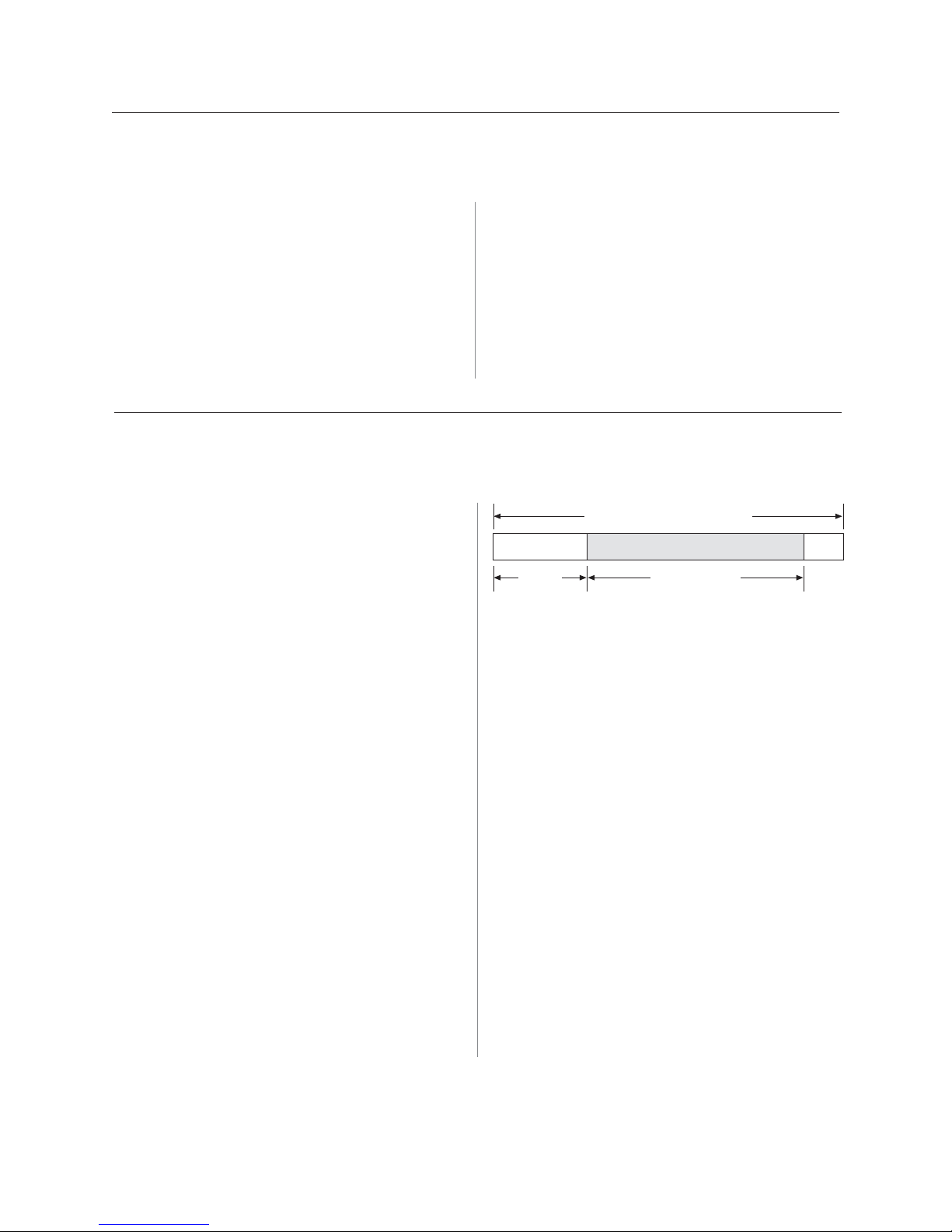
A795 User Guide: Programming Supplement
52
Chapter 4: Programming commands
Select justification
ASCII ESC a n
Hexadecimal 1B 61 n
Decimal 27 97 n
Revision E May 2005
Value of n: 0, 48 = Left aligned
1, 49 = Center aligned
2, 50 = Right aligned
Range of n: 0–2, 48–50
Default: 0 (Left aligned)
Specifies the alignment of characters, graphics, logos,
and bar codes on the receipt station according to the
above table.
Set left margin
ASCII GS L nL nH
Hexadecimal 1D 4C nL nH
Decimal 29 76 nL nH
Range of nL: 0–255
Range of nH: 0–255
Default: 576 dots (the maximum printable area)
Formulas
Sets the left margin of the printing area. The left margin
is set to ((nH X 256) + nL) times horizontal motion unit)
inches. The horizontal motion units are set by the set
horizontal and vertical minimum motion units command
(1D 50), described in this manual.
The width of the printing area is set by the set printing area
width command (1D 57), which follows this command.
See the set printing area width command in this document
for a description of that command.
Related information
On the LEGACY emulation printer, this command is valid
only at the beginning of a line.
Range of n on A793 is 0–255 using low 2 bits only:
00 left aligned
01 center
10 right aligned
11 center
Printable Area 576 Dots
Left
Margin
Exceptions:
Printing Area
Width
The command is effective only at the beginning of a
line. This command is ignored if the line buffer is not
empty, and only effects the receipt interface.
If the setting exceeds the printable area, the maximum
value of the printable area is used. The maximum printable
area is 576 dots. See the illustration.
To set the left margin to one inch at the default
horizontal motion unit of 1/203 inches, send the fourbyte string:
GS L 203 0
Or, to set the left margin to two inches at the default
horizontal motion unit of 1/203 units per inch, send the
four-byte string:
GS L 150 1
Where 2 inches = 406/203, and 406 = (1 X 256) + 150.
Page 53

Revision E May 2005
Set printing area width
ASCII GS W nL nH
Hexadecimal 1D 57 nL nH
Decimal 29 87 nL nH
53A795 User Guide: Programming Supplement
Chapter 4: Programming commands
Range of nL: 0–255
Range of nH: 0–255
Default: 576 dots (the maximum printable area)
Sets the width of the printing area. If the setting exceeds
the printable area, the maximum value of the printable
area is used. The width of the printing area is set to
((nH X 256) + nL) times horizontal motion unit) inches.
The horizontal motion units are set by the set horizontal
and vertical minimum motion units command (1D 50).
The width of the printing area follows the set left margin
command (1D 4C). See the set left margin command
(10 4C …) earlier in this document for a description.
Formulas
To set the width of the printing area to one inch at the
default horizontal motion unit of 1/203 inches, send the
four-byte string:
GS W 203 0
Or, to set the width of the printing area to two inches at the
default horizontal motion unit of 1/203 units per inch,
send the four-byte string:
Printable Area 576 Dots
Left
Margin
Exceptions
Printing Area
Width
This command is effective only at the beginning of a
line.
If the setting exceeds the printable area, the maximum
value of the printable area is used. The maximum
printable area is 576 dots. See the illustration.
GS W 150 1
Where 2 inches = 406/203, and 406 = (1 X 256) + 150.
Page 54

A795 User Guide: Programming Supplement
54
Chapter 4: Programming commands
T ext characteristics commands
These commands control what the printed information looks like, selection of character sets,
definition of custom-defined characters, and setting of margins. The commands are described
in order of their hexadecimal codes.
The commands describe operation for 80mm paper. If the printer supports 82.5mm paper, the
dot spacing is the same but there are 640 printable dots rather than 576 printable dots on 80mm
paper.
Select double-wide characters
ASCII DC2
Hexadecimal 12
Decimal 18
Revision E May 2005
Prints double-wide characters. The printer is reset to
single-wide mode after a line has been printed or the
clear printer (0x10) command is received. Double-wide
characters may be used in the same line with single-wide
characters.
Select single-wide characters
ASCII DC3
Hexadecimal 13
Decimal 19
Prints single-wide characters. Single-wide characters
may be used in the same line with double-wide
characters.
Exceptions
Single-wide characters may not be used in the same line
with single or double-density graphics.
Select 90 degree counter-clockwise rotated print
ASCII ESC DC2
Hexadecimal 1B 12
Decimal 27 18
Rotates characters 90 degrees counter-clockwise. The
command remains in effect until the printer is reset or
until a clear printer (0x10), select or cancel upside down
print (1b 7b) or cancel rotated print (1b 56) command is
received.
Exceptions
Double-wide characters may not be used in the same
line with single or double-density graphics.
Related information
This command is ignored in LEGACY emulation.
Related information
This command is ignored in LEGACY emulation.
Exceptions
This command is valid only at the beginning of a line.
Rotated print and non-rotated print characters cannot
be used together in the same line.
Related information
See “Summary of rotated printing” in this document.
This command is ignored in LEGACY emulation.
Page 55

Revision E May 2005
Select pitch (column width)
ASCII ESC SYN n
Hexadecimal 1B 16 n
Decimal 27 22 n
Value of n: 0 = Standard pitch
1 = Compressed pitch
Default: 0 (Standard pitch)
Selects the character pitch for a print line.
Formulas
The following table provides the print characteristics for
both pitches on the receipt station.
Pitch Columns, Columns, CPI
80mm Paper 82.5mm Paper
Standard 44 49 15.6
Compressed 56 64
20.3
55A795 User Guide: Programming Supplement
Chapter 4: Programming commands
Related information
Look in Chapter 3: Programming the Printer, “Character
appearance” for a description of both pitches.
This command and the select print modes command
(1B 21 n) affect pitch selection.
This is ignored in LEGACY emulation and the parameter
byte goes into the print buffer.
Set right-side character spacing
ASCII ESC SP n
Hexadecimal 1B 20 n
Decimal 27 32 n
Range of n: 0 – 32 (decimal)
Default: 0
The units of horizontal and vertical motion are specified
by the set horizontal and vertical minimum motion units
(1D 50 …) command. Changes in the horizontal or
vertical units do not affect the current right side
character spacing. When the horizontal or vertical
motion unit is changed by the set horizontal and vertical
minimum motion units (1D 50 …) command the
value must be in even units and not less than the
minimum amount of horizontal movement.
In standard mode the horizontal motion unit is used.
In page mode the horizontal or vertical motion unit
differs and depends on the starting position of the
printable area. When the starting printing position is the
upper left or lower right of the printable area (set by
select print direction in page mode, 1B 54 n) the
horizontal motion unit (x) is used. When the starting
printing position is the upper right or lower left of the
printable area (set by select print direction in page
mode, 1B 54 n) the vertical motion unit (y) is used.
Related information
This is ignored in LEGACY emulation and the parameter
byte goes into the print buffer. In the A793 emulation,
the command and parameter byte are ignored.
Page 56

A795 User Guide: Programming Supplement
56
Chapter 4: Programming commands
Select print mode
ASCII ESC ! n
Hexadecimal 1B 21 n
Decimal 27 33 n
Revision E May 2005
Value of n: Pitch selection (standard, compressed,
double high, or double wide.)
Value of n
Bit1Function 0 1
Bit 0 Pitch
2
Standard Compressed
(See chart below) pitch pitch
Bit 3 Emphasized mode Canceled Set
Bit 4 Double-high Canceled Set
Bit 5 Double-wide Canceled Set
Bit 7 Underlined mode Canceled Set
1
Bits 1, 2 and 6 are not used.
2
Standard and compressed pitch cannot be used
together in the same line.
Default: 0 (for bits 0, 3, 4, 5, 7)
This command and select pitch (column width)
command (1B 16 n) affect pitch selection.
Pitch Columns, Columns, CPI
80 mm paper 82.5 mm paper
Exceptions
Refer to the table in other column for exceptions.
Related information
Look in Chapter 3: Programming the Printer, “Character
appearance” for a description of standard and compressed
character pitches.
The bits in this command perform the same function as
the stand-alone functions:
1B 16 n Select pitch
1B 45 n Emphasized
1B 47 n Double-strike
12 Double-wide
13 Single-wide
1B 2D n Underline
Standard 44 49 15.6
Compressed 56 64 20.3
Selects the print mode: standard, compressed,
emphasized, underlined, double-high, or double-wide.
Select or cancel user-defined character set
ASCII ESC % n
Hexadecimal 1B 25 n
Decimal 27 37 n
Value of n: 0 = Code Page 437
1 = User Defined (RAM)
2 = Code Page 850
Range of n: 0–2
Default: 0 (Code Page 437)
Selects the character set. When an undefined RAM
character is selected, the current active ROM code page
character is used. Look in Chapter 3: Programming the
Printer, “Character appearance” for the character sets.
Exception:
The character sets cannot be used together on the
same line.
Related information
In LEGACY emulation, the low order bit of n is used to
select the user-defined character set and the current
active ROM code page is not affected.
Page 57
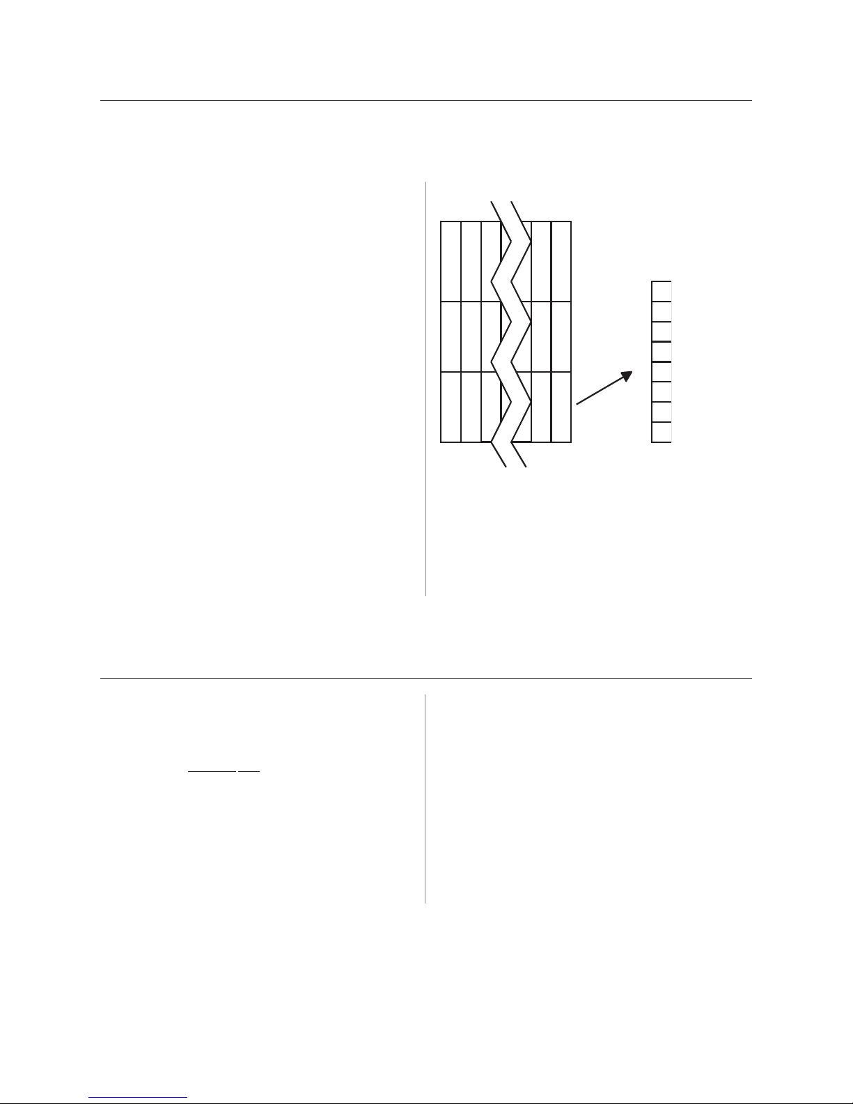
Revision E May 2005
Top of Character
Define user-defined character set
ASCII ESC & s c1 c2 n1 d1 ... nn dn]
Hexadecimal 1B 26 s c1 c2 n1 d1 ... nn dn]
Decimal 27 38 s c1 c2 n1 d1 ... nn dn]
Values and ranges:
s = 3, the number of bytes (vertically) in the character
cell
57A795 User Guide: Programming Supplement
Chapter 4: Programming commands
c = the ASCII codes of the first (c1) and last (c2)
characters
respectively
c1 = Hex 20–FF (20 is always printed as a space)
c2 = Hex 20–FF (20 is always printed as a space)
To define only one character, use the same code
for
both c1 and c2
n = the number of dot columns for the nth character as
specified by n1 ... nn
n = 1–16
d = the column data for the nth character as specified
by d1 ... dn
The number of bytes for a character cell is s x n1.
The bytes are printed down and across each cell.
Defines and enters downloaded characters into RAM.
The command may be used to overwrite single
characters. User-defined characters are available until
power is turned off or the initialize printer command (1B
40) is received.
d1
d4
MSB
d2
d5
dn
d3
dn
LSB
Any invalid byte (s, c1, c2, n1) aborts the command.
Related information
See 1D 22 n (select memory type) to save user-defined
characters
Select or cancel underline mode
ASCII ESC - n
Hexadecimal 1B 2D n
Decimal 27 45 n
Value of n:
mode
thickness
Default: 0 (Cancel underline mode)
DecimalHex
0, 48 30 = Cancel underline
1, 49 3 1 = Select underline mode
2, 50 32 = Select double
underline mode
Turns underline mode on or off. Underlines cannot be
printed for spaces set by the horizontal tab, set absolute
start position, or set relative print position commands.
This command and the Select Print Mode(s) command
(1B 21) turn underline on and off in the same way.
Exceptions
This command is ignored if n is out of the specified
range.
Page 58

A795 User Guide: Programming Supplement
58
Chapter 4: Programming commands
Related information
In A793 emulation, this command is unrecognized and the parameter n is put into the print buffer.
Copy character set from ROM to RAM
Revision E May 2005
ASCII ESC : 0 0 0
Hexadecimal 1B 3A 30 30 30
Decimal 27 58 0 0 0
Default: Current active ROM code page
Copies characters in the active ROM set to RAM. Use
this command to re-initialize the user-defined character
set. Code page 437 is copied by default at initialization.
This command is ignored if current font is the user font.
Cancel user-defined character
ASCII ESC ? n
Hexadecimal 1B 3F n
Decimal 27 63 n
Value of n: Specified character code.
Range of n: 32–255
Exceptions
This command is ignored if n is out of range or if the
user-defined character is not defined.
Related information
To modify characters in one of the character set
variations, such as rotated print, select one of the
rotated print commands, copy to RAM, then use the
define user-defined character set command (1B 26).
Cancels the pattern defined for the character code
specified by n. After the user-defined character is
canceled, the corresponding pattern from current active
ROM code page is printed.
Select or cancel emphasized mode
ASCII ESC E n
Hexadecimal 1B 45 n
Decimal 27 69 n
Value of n: 0 (bit 0) not selected
1 (bit 0) selected
(When 0 and 1 are the least
significant bit, LSB)
Range of n: 0-255
Default: 0 (Off)
Starts or stops emphasized printing. The printer is reset
to the standard print mode after a clear printer (0x10)
command is received.
Exceptions
Only the lowest bit of n is effective.
Emphasized printing cannot be used with bit-images or
downloaded bit-images.
Related information
This command and the select print mode(s) command
(1B 21) function identically. They should have the same
setting when used together.
In A793 emulation, this command is unrecognized and
the parameter byte is put into the print buffer.
Page 59

Revision E May 2005
Select or cancel double-strike
ASCII ESC G n
Hexadecimal 1B 47 n
Decimal 27 71 n
59A795 User Guide: Programming Supplement
Chapter 4: Programming commands
Value of n: 0 = Off
1 = On
(When 0 and 1 are the
least significant bit, LSB)
Default: 0 (Off)
Turns double-strike mode on or off. Identical to
emphasized mode. The printer is reset to the standard
print mode after a clear printer (0x10) command is
received.
Select or cancel italic print
ASCII ESC I n
Hexadecimal 1B 49 n
Decimal 27 73 n
Value of n: 0 = Off
1 = On
(When 0 and 1 are the least
significant bit, LSB)
Default: 0 (Off)
Turns italic print mode on or off. The printer is reset to
the standard print mode after a clear printer (0x10)
command is received.
Exceptions
Only the lowest bit of n is effective. The settings do not
apply in page mode. However they can be set or cleared
in page mode.
Double-strike printing cannot be used with bit-images or
downloaded bit-images.
Related information
This command and the select print mode(s) command
(1B 21) function identically. They should have the same
setting when used together.
In A793 emulation, this command is unrecognized and
the parameter byte is put into the print buffer.
Exceptions
Only the lowest bit of n is valid.
Related information
This command is recognized in A795 native mode and
A794 emulation.
In A793 and LEGACY emulations, the parameter byte is
put into the buffer.
Page 60

A795 User Guide: Programming Supplement
60
Chapter 4: Programming commands
Revision E May 2005
Select international character code
ASCII ESC R n
Hexadecimal 1B 52 n
Decimal 27 82 n
Value of n:
A795 native mode A793 emulation Application Compatible Escape Command
emulation
(1B 52 n only)
0 = Code Page 437 0 = Code Page 437 0 = U.S.A.
1 = Code Page 850 Not 0 = Code Page 850 1 = France
2 = Code Page 852 2 = Germany
3 = Code Page 860 3 =-U.K.
4 = Code Page 863 4 = Denmark I
5 = Code Page 865 5 = Sweden
6 = Code Page 858 6 = Italy
7 = Code Page 866 7 = Spain
8 = Code Page 1252 8 = Japan
9 = Code Page 862 9 = Norway
10 = Code Page 737, Greek (only in A795 native mode)
Default: 0 (Code Page 437)
Selects the character set to be used. Look in “Appendix
B: Resident Character Sets” in the A795 User Guide for
the character sets.
There are two codes for this command (see select
international character set, 1B 74 n). Both codes perform
Related information
The LEGACY emulation selection applies only to the
command “Select international character code” (1B 52
n). The LEGACY emulation generates the same as A795
native mode for the command “Select international
character set table” (1B 74 n).
the same function.
Select or cancel 90 degree clockwise rotated print
ASCII ESC V n
Hexadecimal 1B 56 n
Decimal 27 86 n
Value of n: 0 = Cancel
1 = Set
Default: 0 (Cancel)
Rotates characters 90 degrees clockwise. The command
remains in effect until the printer is reset or until a clear
printer (0x10) or rotated print (1B 12) command is
received. See summary of rotated printing in this
document.
Page 61

Revision E May 2005
Chapter 4: Programming commands
Select international character set
ASCII: ESC t n
Hexadecimal: 1B 74 n
Decimal: 27 116 n
Value of n:
A795 native mode A793 emulation Application Compatible Escape Command
emulation
(1B 52 n only)
0 = Code Page 437 0 = Code Page 437 0 = U.S.A.
1 = Code Page 850 Not 0 = Code Page 850 1 = France
2 = Code Page 852 2 = Germany
3 = Code Page 860 3 =-U.K.
4 = Code Page 863 4 = Denmark I
5 = Code Page 865 5 = Sweden
61A795 User Guide: Programming Supplement
6 = Code Page 858 6 = Italy
7 = Code Page 866 7 = Spain
8 = Code Page 1252 8 = Japan
9 = Code Page 862 9 = Norway
10 = Code Page 737, Greek (in A795 native mode and A794 emulation)
Default: 0 (Code Page 437)
Selects the character set to be used. Look in “Appendix
B: Resident Character Sets” in the A795 User Guide
Programming Supplement for the character sets.
There are two codes for this command (See “Select
international character code, 1B 52 n.) Both codes
perform the same function.
Related information
The LEGACY emulation selection applies only to the
command “Select international character code” (1B 52
n). The LEGACY emulation generates the same as A795
native mode for the command “Select international
character set” (1B 74 n).
Select or cancel upside-down print mode
ASCII ESC { n
Hexadecimal 1B 7B n
Decimal 27 123 n
Value of n: 0 = Cancel
1 = Set
Default: 0 (Cancel)
Prints upside-down characters. The command may be
combined with clockwise rotated print (1B 56) or
counter-clockwise rotated print (1B 12). The character
Exceptions
The command is valid only at the beginning of a line.
It cannot be used with right side up characters on the
same line.
order is inverted in the buffer so text is readable. Only
bit 0 is used. Bits 1-7 are not used. See summary of
rotated printing in this document for more information.
Page 62

A795 User Guide: Programming Supplement
62
Chapter 4: Programming commands
Select character size
ASCII GS ! n
Hexadecimal 1D 21 n
Decimal 29 33 n
Revision E May 2005
Value of n: 1–8 = vertical number of times active
font
1–8 = horizontal number of times
active font
Range of n: 00–07, 10–17, ...70–77
Default of n: 11 hexadecimal
Selects the character height using bits 0 to 2 and selects
the character width using bits 4 to 6, as follows:
With smoothing enabled, maximum value of 0+n is 66.
Character width selection
Hex Decimal Width
00 0 1 (normal)
10 16 2 (two times width)
20 3 2 3 (three times width)
30 4 8 4 (four times width)
40 6 4 5 (five times width)
50 80 6 (six times width)
60 9 6 7 (seven times width)
This command is effective for all characters (except for
HRI characters).
In standard mode, the vertical direction is the paper feed
direction, and the horizontal direction is perpendicular
to the paper feed direction. However, when character
orientation changes in 90 degree clockwise-rotation
mode, the relationship between vertical and horizontal
directions is reversed.
In page mode, vertical and horizontal directions are
based on the character orientation. When characters are
enlarged with different sizes on one line, all the
characters on the line are aligned at the baseline.
The select print mode (1B 21 n) command can also select
or cancel double-width and double-height modes.
However, the setting of the last received command is
effective.
Exceptions
If n is out of the defined range, this command is ignored.
In native mode, the vertical direction is limited to 7
®
(seven times height) when Tall or ColorPOS
font is
selected. If 8 (eight times height) is selected, the results
are unspecified.
70 112 8 (eight times width)
Character height selection
Hex Decimal Height
0 0 1 (normal)
0
01 1 2 (two times height)
02 2 3 (three times height
03 3 4 (four times height)
04 4 5 (five times height)
05 5 6 (six times height)
06 6 7 (seven times height)
07 7 8 (eight times height)
Related information
In A793 emulation, this command is discarded and not
put into print buffer.
Page 63

Revision E May 2005
Select or cancel white/black reverse print mode
ASCII GS B n
Hexadecimal 1D 42 n
Decimal 29 66 n
63A795 User Guide: Programming Supplement
Chapter 4: Programming commands
Value of n: 0 = Off
1 = On
(When 0 and 1 are the least
significant bit, LSB)
Range of n: 0–255
Default: 0 (Off)
Turns on white/black reverse print mode. In white/black
reverse print mode, print dots and non-print dots are
reversed, which means that white characters are printed
on a black background. When the white/black reverse
print mode is selected it is also applied to character
spacing which is set by right-side character spacing (1B
20).
This command can be used with built-in characters and
user-defined characters, but does not affect the space
between lines.
White/black reverse print mode does not affect bit
image, downloaded bit image, bar code, HRI characters,
and spacing skipped by horizontal tab (09), set absolute
starting position (1B 24 …), and set relative print
position (1B 5C).
White/black reverse print mode has a higher priority
than underline mode. When underline mode is on and
white/black reverse print mode is selected, underline
mode is disabled, but not canceled.
Bar codes, logos, and bit images are not affected by this
command.
Exceptions
Only the lowest bit of n is valid.
Related information
If the current color is not black and two-color paper is
loaded, no visible effect takes place.
In A793 emulation, the command is unrecognized and
the parameter byte is put into the print buffer.
Reverse color text mode (ColorPOS®)
ASCII GS 0x85 m n
Hexadecimal 1D 85 m n
Decimal 29 133 m n
Value of m: 0 = white
1 = black
2 = paper color
Value of n: 0 = white
1 = black
2 = paper color
Default: m = 0 (off)
Sets a mode for reverse printing effects on text. The
background color is specified by m, while the text color
is specified by n. Setting m = 0 turns off the mode.
If m = n but not zero, the printer produces solid printing
in the given color. This tactic can be used to minimize
the firmware busy work.
The value of current color and white/black reserve print
mode is superceded by the value of n whenever this
mode is on (m>0).
Bar codes, logos, and bit images are not affected by this
command.
Page 64

A795 User Guide: Programming Supplement
64
Chapter 4: Programming commands
T ext strike-through mode (ColorPOS®)
ASCII GS 0x85 m n
Hexadecimal 1D 8D n m
Decimal 29 141 n m
Value of m: 0 = retain same color as the character
itself
1 = black
2 = paper color
Value of n: standard cell height
Default: n = 0 (off)
Prints a strike-through over characters. If the strikethrough is as wide as the cell height, this will produce a
cell that will be printed as a solid current color.
Select superscript or subscript modes
ASCII AX ENQ n
Hexadecimal 1F 05 n
Decimal 31 05 n
Revision E May 2005
When characters are greater than normal size, such as
double-high, the number of character rows claimed by n
also increases proportionally, such as doubling for
double-high cells. Location of the strike-through on a
cell is on a cell-by-cell basis, so mixing cell sizes on the
same print row will give uneven results.
Value of n: 0 = Normal character size
1 = Select subscript size
2 = Select superscript size
Default: 0 (normal size)
Turns superscript or subscript modes on or off. This
attribute may be combined with other characters size
settings commands (12, 13, 1B 21 n, 1D 21 n,…)
Exceptions
This command is ignored if n is out of the specified
range.
Related information
In A793 emulation, this command is unrecognized and
the parameter byte is put into the print buffer.
Page 65

Revision E May 2005
Chapter 4: Programming commands
Graphics
These commands are used to enter and print graphics data and are described in order of their
hexadecimal codes.
These commands describe operation for 80mm paper. If the printer supports 82.5mm paper, the
dot spacing is the same but there are 640 printable dots rather than 576 printable dots on 80
mm paper.
Download BMP logo
ASCII: ESC (+*.BMP file)
Hexadecimal: 1B (+*.BMP file)
Decimal: 27 66 77(+*.BMP file)
Value: Maximum width = 576 (640 for 82.5mm
paper)
Maximum height = 51 2
Enters a downloaded BMP logo into RAM or flash.
The downloaded BMP logo can be printed by using the
print downloaded bit image (1D 2F m) command.
To downloaded BMP file to save it as a logo, send the
hexadecimal code 1B followed by the whole BMP file.
The printer decodes the BMP file header and will save
the image data after checking important parameters,
such as:
- Width,
- Height,
- Number of colors
(only monochrome images are
accepted)
BMPs and bit images continue to be definable only for
the receipt station. However, there is no longer an
automatic erasure whenever the user downloads a
character set (as happened previously) as well as in the
case where the current logo was never set > 0, (the
automatic erasure if user flash memory had filled up with
inactive logo 0 definitions upon next power cycle).
Warnings about the effect of running out of defined
logo space during a download apply (i.e. the command
is ignored). The application is required to manage user
data space, downloaded font space, and logo space.
After downloading a logo to the printer, wait 100ms to
allow the printer time to write the logo to flash.
Exceptions
BMP file images that are not monochrome are put into
the print buffer.
Related information
65A795 User Guide: Programming Supplement
Microsoft BMP bitmap file format.
This command is recognized in A795 native mode and in
A794 emulation.
In A793 and LEGACY emulations, the BMP file bytes are
put into the print buffer.
Page 66
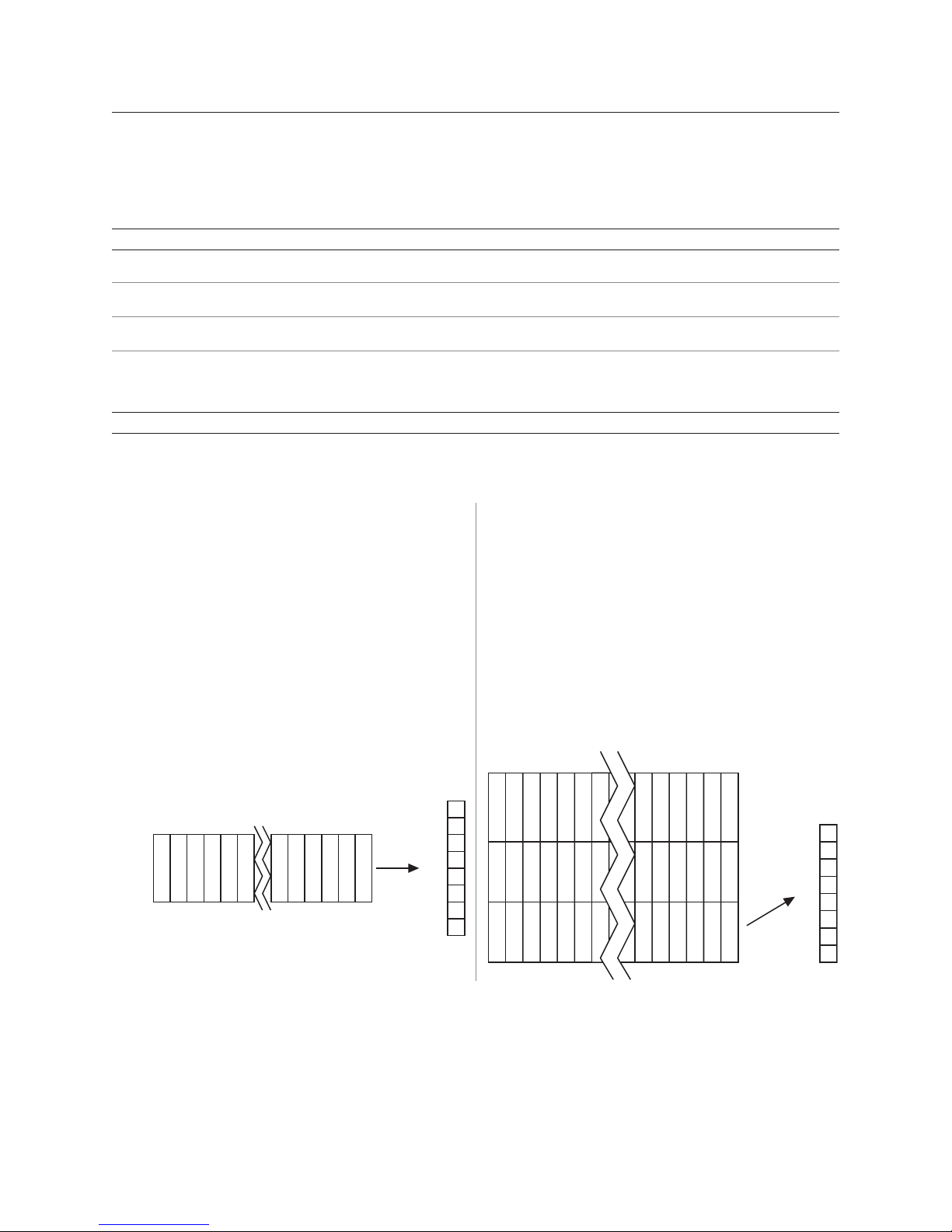
A795 User Guide: Programming Supplement
pt
8-Dot single-density mode
24-Dot single-density mode
66
Revision E May 2005
Chapter 4: Programming commands
Select bit image mode
ASCII ESC * m n1 n2 d1 ... dn
Hexadecimal 1B 2A m n1 n2 d1 ... dn
Decimal 27 42 m n1 n2 d1 ... dn
Value of m:
Value of m Mode No. of dots (vertical) No. of dots (horizontal) No. of dots/line
0 8-dot single-density 8 (68 DPI) 0–288 (101 DPI) 8 x 288
1 8-dot double-density 8 (68 DPI) 0–576 (203 DPI) 8 x 576
32 24-dot single-density 24 (203 DPI) 0–288 (101 DPI) 24 x 288
33 24-dot double-density 24 (203 DPI) 0–576 (203 DPI) 24 x 576
Value of n:
Value of n (8-dot single-density mode) Value of n (24-dot single-density mode) Value of d
n1 + (256 x n2) 3 x [n1 + (256 x n2)] Number of bytes of data*
*Printed left to right (8-dot mode); printed down then across (24-dot mode)
Formulas
8-dot single-density= n1 + (256 X n2)
24-dot single-density= 3 X [n1+ (256 X n2)]
Sets the print resolution and enters one line of graphics
data into the print buffer. Excess data is accepted but
ignored. Any print command is required to print the
data, after which the printer returns to normal
processing mode.
Top of bit image
d4 d3 d2 d1 dn
MSB
dn
LSB
Recei
See the illustration for graphic representations of the bit
image below.
Top of bit image
d4 d7
d1
MSB
d2
d5
dn
d3
d6 dn
LSB
Page 67

Revision E May 2005
Print advanced raster graphics
ASCII ESC . m n rL rH d1 … dn
Hexadecimal 1B 2E m n rL rH d1 … dn
Decimal 27 46 m n rL rH d1 … dn
Value of m: horizontal offset from left
margin = 8 x m dots
Value of n: number of data bytes that
compose the raster
Value of r: number of times the raster has
to be printed =256 x rH + rL
d1 … dn: data bytes
Range: 0<= m <= 72
0<= n <= 72
0<= r <= 65535
0<= d1 … dn <= 255
Select single-density graphics
ASCII ESC K n1 n2 d1 ... dn
Hexadecimal 1B 4B n1 n2 d1 ... dn
Decimal 27 75 n1 n2 d1 ... dn
67A795 User Guide: Programming Supplement
Chapter 4: Programming commands
Prints a horizontal raster of graphics data one or multiple
times. Horizontal offset and number of data bytes are
variable and specified by parameters.
Exceptions
Advanced raster graphics is not available in page mode.
Value of n:
Value of n (8-dot single-density mode) Value of d
n1 + (256 x n2) Number of bytes of data
(printed down, then across)
Enters one line of 8-dot single-density graphics into the
print buffer. Any print command is required to print the
line, after which the printer returns to normal processing
mode. Single-density mode allows 0–288 dot columns.
The number of bytes sent is represented by the formulas in
the table.
Each bit corresponds to two horizontal dots. Compare to
set bit image mode (1B 2A, m=0) earlier in this
document.
Related information
In LEGACY emulation, this command is unrecognized
and the parameters are put into the print buffer.
Page 68

A795 User Guide: Programming Supplement
68
Chapter 4: Programming commands
Select double-density graphics
ASCII ESC Y n1 n2 d1 ... dn
Hexadecimal 1B 59 n1 n2 d1 ... dn
Decimal 27 89 n1 n2 d1 ... dn
Value of n:
Value of n (8-dot single-density mode) Value of d
n1 + (256 x n2) Number of bytes of data
(printed down, then across)
Revision E May 2005
Enters one line of 8-dot double-density graphics into
the print buffer. Any print command is required to print
the line, after which the printer returns to normal
processing mode. Double-density mode allows 0–576
dot columns. The number of bytes sent is represented
by the formulas in the table.
Select the current logo
ASCII GS # n
Hexadecimal 1D 23 n
Decimal 29 35 n
Range of n: 0 – 255
Default: 0
Selects a color or monochrome logo to be defined or
printed. The active logo n remains in use until this
command is sent again with a different logo n.
When this command precedes a logo definition, that
definition is stored in flash or RAM memory as logo n. If
there is already a different definition in flash memory for
logo n, the first is inactivated and the new definition is
used. The inactive definition is not erased from flash
and continues to take up space in flash memory.
When this command precedes a logo print command
and n is different from the previously active logo
selected, the printer retrieves the logo definition for n
from flash or RAM memory and prints it. If there is no
definition for logo n, then no logo is printed.
Each bit corresponds to one horizontal dot. Compare to
set bit image mode (1B 2A, m=1) earlier in this
document.
Related information
In LEGACY emulation, this command is unrecognized
and the parameters are put into the print buffer.
In the case of a previously existing application that
expects only one possible logo, the printer will not
receive the select current logo (1D 23 n) command. In
this case, the printer assigns 0 as the active logo
identifier. It automatically stores any new logo definition
in flash memory as logo 0, inactivating any previous
logo 0 definition. If the flash memory space available for
logos fills up with inactive logo 0 definitions, the
firmware erases the old definitions at the next power
cycle. This is the only case in which the printer erases
flash memory without an application command.
In the case of a new application using multiple logos,
the select current logo (1D 23 n) command is used. After
that, the printer no longer automatically erases the logo
definition flash memory page when it fills with multiple
definitions. A new application using multiple logos,
writing a user-defined character set into flash memory,
or both, is responsible for erasing the logo and userdefined character set flash memory page when the logo
area is full or before a new character set is defined.
Related information
This command is recognized in A795 native mode and
A794 emulation.
In A793 and LEGACY emulations, the parameters are put
into the print buffer.
Page 69
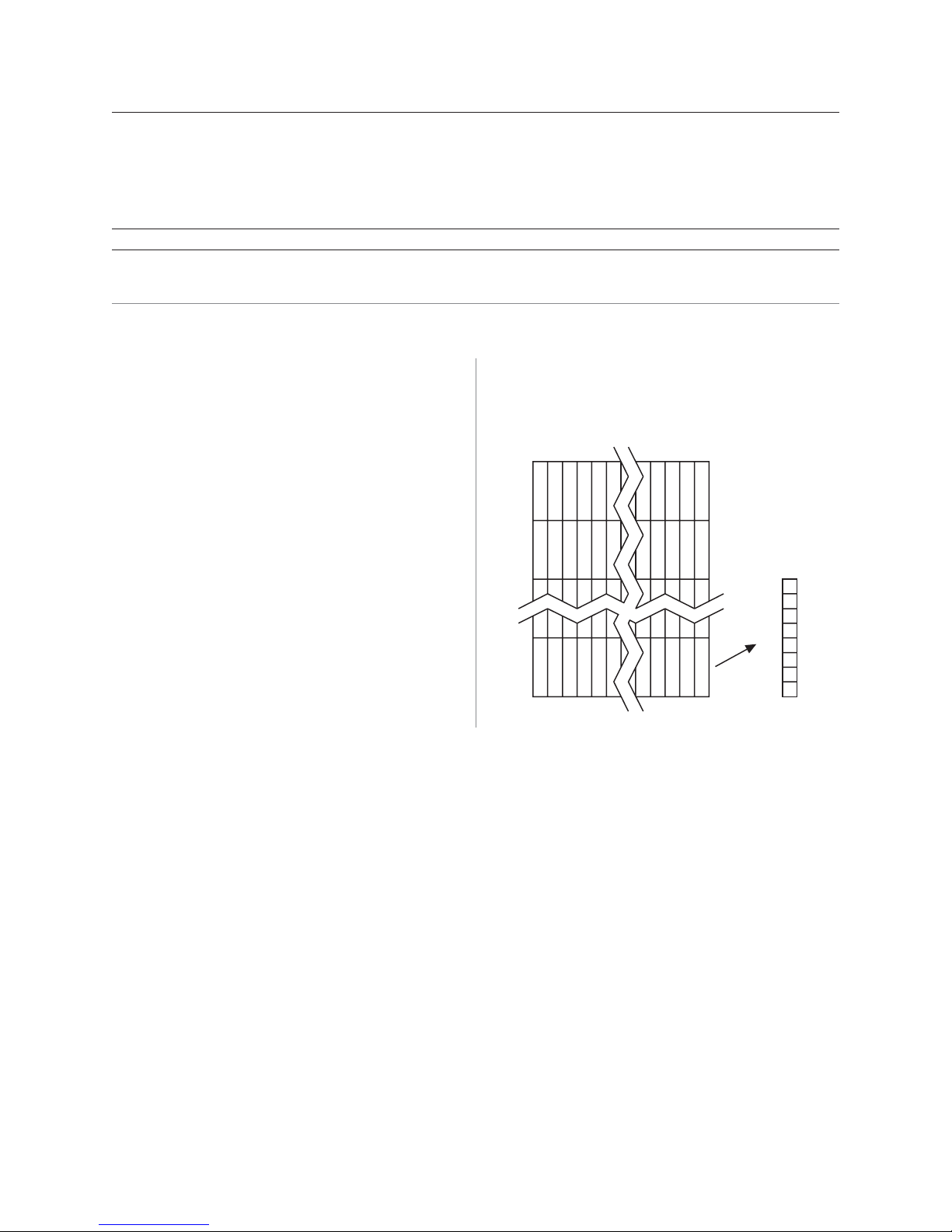
Revision E May 2005
Top of graphic
Chapter 4: Programming commands
Define downloaded bit image
ASCII GS * n1 n2 d1 ... dn]
Hexadecimal 1D 2A n1 n2 d1 ... dn]
Decimal 29 42 n1 n2 d1 ... dn]
Value of n:
Value of n1 Value of n2 V alue of d
1–72 (8 x n1 = number of 1–64 (number of vertical bytes)
horizontal dot columns) (printed down, then across)
1
The number of bytes sent is represented by the following formula:
n = 8 x n1 x n2 (n1 x n2 must be less than or equal to 4608).
1
Bytes of data
69A795 User Guide: Programming Supplement
Enters a downloaded bit image (such as a logo) into
RAM or flash with the number of dots specified by n1
and n2. If in RAM, the downloaded bit image is
available until power is turned off, another bit image is
defined, or initialize printer (1B 40) command is received.
This bit image will be saved as a monochrome logo
indexed by current value that was last set by the select
current logo command or 0 is a select current logo
command had not yet been given.
See the illustration below for a graphic representation of
the downloaded bit image.
Column
one 72 x 8 max.
Row
one
d
d1
65
d2
d
Row 64
max.
64
Column
MSB
dn
dn
LSB
Page 70

A795 User Guide: Programming Supplement
70
Chapter 4: Programming commands
Print downloaded bit image
ASCII GS / m
Hexadecimal 1D 2F m
Decimal 29 47 m
Revision E May 2005
Value and range of m:
This command is used to print a previously stored
monochrome or color logo from printer memory on the
receipt station. The logo is identified as the one
indicated by the most recent select current logo
command or 0 if a select current logo command has not
yet been given. Parameter m is interpreted as follows:
Value of m Print mode Vertical DPI Horizontal
DPI
0 Normal 203 203
The indexed downloaded bit image from RAM or flash
will be printed on the receipt station at a size specified
by m. If the bit image is a monochrome one, it is printed
in the current color; otherwise it is printed as a twocolor image. If doubling or quadrupling exceeds the
print paper width maximums (576 or 640 with 82.5mm
paper) the left side of the image is printed and the bits to
the right of the maximum column are discarded. If the
available width is greater than the bit image, its printing
will adhere to any currently set right, left, or center
justification. This command is ignored if the index refers
to an undefined logo/ bit image.
1 Double wide 2 03 101
2 Double high 101 203
3 Quadruple 101 101
Print raster monochrome graphics (ColorPOS®)
ASCII GS 0x82 n1…..n72 (576 dots) for 80 mm paper, or n80 (640 dots) for 82.5 mm paper
Hexadecimal 1D 82 n1…..n72 (576 dots) for 80 mm paper, or n80 (640 dots) for 82.5 mm paper
Decimal 29 130 n1…..n72 (576 dots) for 80 mm paper, or n80 (640 dots) for 82.5 mm paper
Value and range of n:n1 to n72/n80 corresponds to
one dot row data for a thermal
receipt printer.
Each bit defines whether or not a dot of the current
dot rows.
If two-color paper is indicated by the set paper type
command, then the raster will be printed in the color that
is defined by the set current color command.
color will be printed. This command is used for printing
a monochrome graphic in real-time. Offsets, page and
any other modes or overlays, including watermark do
MSB
n
LSB
not apply and are overridden by this command. A
complete rendering of the intended final image should
n1 n2
n3
...
n72/80
have been done by the application before sending the
Page 71
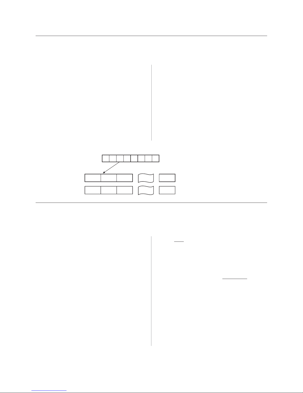
Revision E May 2005
Chapter 4: Programming commands
Print raster color graphics (ColorPOS®)
ASCII GS 0x83 n1…..n144 (576 dots 80mm paper) / n160 (640 dots, 82.5mm paper)
Hexadecimal 1D 83 n1…..n144 (576 dots 80mm paper) / n160 (640 dots, 82.5mm paper)
Decimal 29 13 n1…..n144 (576 dots 80mm paper) / n160 (640 dots, 82.5mm paper)
Value and range of n:
For each printed dot row starting at the top left, two-part
bit strings are used to define (in the first half), all dots
that are of either color (i.e. not white). The second half
string defines only the dots where the color = black.
n1 to n144 / n160 corresponds to
one dot row data.
This command is used for printing a single raster of
color graphics in real-time. Offsets, page and any other
modes or overlays, including watermark, and current
color do not apply to this command. A complete
rendering of the intended final image has to be done by
the application before sending the dot rows.
Thus all dots which are on in the first half string but not
on in the second half string, select the secondary color.
The parameter of this command is thus a string of bytes
for
one dot row with the same structure as defined for the
thermal color format file given in the download color
logo command.
71A795 User Guide: Programming Supplement
MSB
n1 n2
nb1 nb2
n3
nb3
n
LSB
...
...
Download logo image (ColorPOS®)
ASCII GS 0x84 m n1 n2 d1…..dx , x = (n1 * n2*8 ) * m
Hexadecimal 1D 84 m n1 n2 d1…..dx , x = (n1 * n2*8 ) * m
Decimal 29 132 m n1 n2 d1…..dx , x = (n1 * n2*8 ) * m
Value of m: 1 = monochrome
2 =two-color
Max n1 = 576/8 for 80mm paper or
640/8 for 82.5mm paper
The latest value from the set current logo command will
be the logo index to be used to store the downloaded
graphic.
For each
parameter byte string is used to define first, all dots that
are not white, and the second half defines all dots where
the color = black. Thus all dots that are on (=1) in the
first half but not on in the second half select the papercolor. A sequence of these raster row strings is used to
specify the complete logo. In the
only one bit is needed per row. This is the same
m identifies whether the image is monochrome (which
requires one parameter bit row description) or two-color,
structure as used for the definitions of print raster
monochrome graphics and print raster color graphics.
which requires a pairing of bit descriptions for each row.
This command is used for storing a logo of n1 by n2
n1 * n2 define a rectangular image n1 bytes wide and n2
size indexed by the current logo value.
bytes long. n1*8 specifies the number of dot columns,
and n2*8 the number of dot rows. That is, each row is
defined by an integral number of bytes and the number
After downloading a logo to the printer, wait 100ms to
allow the printer time to write the logo to flash.
of rows is also an integral number of bytes. Note that n2
can be any length, subject to memory space availability.
n72/80
nb72/80
All dots parameter
Black dots parameter
color dot row starting at the top left, a two part
monochrome case,
Page 72

A795 User Guide: Programming Supplement
72
Chapter 4: Programming commands
Apply shading to logo (ColorPOS®)
ASCII GS Ox8B n m o
Hexadecimal 1D 8B n m o
Decimal 29 139 n m o
Revision E May 2005
This command will apply shading effect m to logo n and
store it at index o, also extending width to full horizontal
size if logo n is not at full paper width.
n must be the index value of an existing logo
0 <= m <= 100, possibly resulting in a logo suitable for
background watermark mode use
o can be any value, and the logo will be placed
according to the current setting of user storage into
RAM or flash memory.
An application might use a high value of m to shade out
the logo if the original image has a significant number of
“on” dots to allow for future foreground print
readability.
Merge watermark mode (ColorPOS®)
ASCII GS Ox8C n m
Hexadecimal 1D 8C n m
Decimal 29 140 n m
Default 0 (off)
This command will insert the logo m as a repeated
background image, similar to printing a visible watermark,
into the print stream. The space between repetitions of this
usually shaded logo will be every n*8 dot rows.
n >0 = number of dot rows x8 to skip before repeating the
merge action
m specifies the index value of the logo. If no logo has been
defined with this index then the command is ignored.
Note: The old logo size and current justification mode
are used to create a new logo image at full paper width
size by filling in white space at either or both sides if
needed. This new logo will provide for minimal
performance impacts when it is selected for use in
watermark mode.
After sending the shading command, wait 5 seconds to
allow the printer to apply the shading and write the
results to flash.
Note: Horizontal placement of a watermark logo was
fixed at the time the logo was Shaded or when it was
downloaded as a full width logo for watermark use. This
command will be ignored if the current logo is not at full
paper width size (see the apply shading to logo command
for preparing logos for watermark use).
The merge process is performed after all other image
formation and takes whatever print raster data is ready to
be put on paper. It “adds” (computer logic OR) the mono
or color bits to the print row. Generally, if the print dot was
to be white or same color as the watermark dot, the print
dot will be the color of the watermark; otherwise it will be
black.
Page 73

Revision E May 2005
Monochrome shade mode (ColorPOS®)
ASCII GS 0x86 m
Hexadecimal 1D 86 m
Decimal 29 134 m
73A795 User Guide: Programming Supplement
Chapter 4: Programming commands
This applies a selected shade density to all monochrome
objects such as text and monochrome logos. The
parameter m specifies the shading effect and has an
initial value of 0 which signifies no effect.
m specifies the percentage of shading, 0 <= m <= 100.
m = 0 is the initial value and turns this mode off.
Note: that only a few gradations will be perceptible, so
large increments of m, such as 20, should be used. If a
reverse print mode is on, the shade effect will be
applied to the
background only.
Color shade mode (ColorPOS®)
ASCII GS 0x87 m
Hexadecimal 1D 87 m
Decimal 29 135 m
This applies a mixing of color into any monochrome
objects such as text and monochrome logos. Rather
than fading away, this mode transitions a character or
logo from the current color in which it would normally
be printed to the other color. The parameter m specifies
the shading effect and has an initial value of 0 which
signifies no effect. m specifies the percentage of
shading, 0 <= m <= 100.
m specifies the percentage of shading, 0 <= m <= 100.
When the current color mode is set to black, increasing
values of m relate to the relative amount of (white) paper
that replaces black dots. Analogously, when the papercolor is the current color, m defines the relative amount of
color dots being “erased” by white originals of the paper.
Both text and monochrome graphics are affected by this
command.
Turning monochrome shade mode on, turns color shade
mode off.
Note: that only a few gradations will be perceptible, so
large increments of m, such as 20, should be used. If a
reverse print mode is on, the shade effect will be applied
background only.
to the
When the current color mode is set to black, increasing
values of m relate to the relative amount of paper-color that
replaces black dots. Analogously, when the paper-color is
the current color, m defines the relative amount
of black color dots replacing the paper-color ones.
m = 0 is the initial value and turns this mode off.
Logo print with color plane swap (ColorPOS®)
ASCII GS 0x89 n m
Hexadecimal 1D 89 n m
Decimal 29 137 n m
This command will print logo n. The command is
ignored if a logo with index n has not been defined. If m
= 0 the color(s) as defined in the logo are used; if m = 1
Both text and monochrome graphics are affected by this
command.
Turning color shade mode on, turns monochrome shade
mode off.
and if the logo is a color one, then the two color planes
(black and paper-color) in the logo are swapped.
Page 74

A795 User Guide: Programming Supplement
74
Chapter 4: Programming commands
Form and merge real time surround graphic (ColorPOS®)
ASCII GS 0x90 m x y o p q
Hexadecimal 1D 90 m x y o p q
Decimal 29 144 m x y o p q
Revision E May 2005
This command will print a real-time graphic style
designated by m. m = 0 rectangle, m =1 oval, m =2 ellipse
(if printed in a square area the ellipse becomes a circle),
m = 3 is a 5 point star, m = 4 is a free hand underline,
m = 5 is a free hand ellipse and other values of m
reserved for future styles. This graphic is formed into a
RAM based graphics buffer, and the buffer state is set
to “graphic merge pending”.
Whenever the buffer is in the pending merge state and
print output is started, the state will be changed to
frozen and a merge process started (logically OR-ed
graphic data) into the print lines that follow. The
application determines how close the graphic is to any
printed character data by subsequent printing of blank
lines or blank dot rows. The merge process stops when
the buffer is exhausted or its state changed (by a save
graphics buffer as logo or new form and merge real time
surround graphics command). The form and merge real
time surround graphics command can be given multiple
consecutive times, allowing the application to set up a
multi-polygon background before starting its printout
with placed text or logo.
The geometric location points for this graphic are
defined by a rectangular area start position of x bytes
from the left edge and y bytes from the top of the new
line and times
o bytes wide times p bytes in length. For the case of
m =3 (star), the value passed for o is also used as the
implicit p value (passed value is ignored), i.e. a square
area. The thickness of the graphic is defined by q dots.
This will form a bit image in a RAM graphics buffer.
Subsequent surround graphic commands can be added
into (logical OR process) with expanded size if needed)
the graphics buffer until an output action is issued. It is
expected that area left white will then be (usually) filled
in with text or other data that is to be printed. Printing
starts as soon as the first line of data or other printout
arrives. After this printing is started, any new surround
graphics commands will set the graphics buffer to a
merge pending state. Example: Create different size stars
and an ellipse around a block of text.
The graphics buffer is at a frozen state at printer
initialization or reset, with blank data in it.
Each the time this command is given, the current color
and shade mode values (if any) are used for the
surround graphic, and may be changed before any
subsequent surround graphics and/or printing output.
This command may be used in page mode.
Save graphics buffer as logo (ColorPOS®)
ASCII GS 0x91 n
Hexadecimal 1D 91 n
Decimal 29 145 n
This command will save all the raster data that is in the
working graphics buffer (where surround graphics are
formed) as a logo with index value n. This logo can then
be used repeatedly for inserting different text. See the
background logo print command.
There is one working graphics buffer in the printer; its
size (and that of the saved logo) is of maximum print
width size, and of sufficient length to store the largest of
the surround graphic styles defined since the last buffer
“freeze” event. This command is ignored if the graphics
buffer is not in a “merge pending” state. The graphics
buffer state will be set to “frozen” by this command.
Related information
This command is ignored in page mode.
Page 75

Revision E May 2005
Background logo print mode (ColorPOS®)
ASCII GS 0x92 n
Hexadecimal 1D 92 n
Decimal 29 146 n
75A795 User Guide: Programming Supplement
Chapter 4: Programming commands
This command will place into the graphics buffer the
logo designated by n. As soon as there is a print action
command (such as text output) the graphics buffer will
be merged (logical OR process) with print output.
Apply margin message mode (ColorPOS®)
ASCII US 0x99 l m n o
Hexadecimal: 1D 99 l m n o
Decimal: 29 155 l m n o
Value of l: l is a binary switch:
l = 0 disables margin message merging
l = 1 enable left margin message merging
l = 2 enable right margin message
merging
l> 2 ignore command
Value of m: m is the ID (index) of the logo to be used in
the merging. If a logo with index m does not exist or is wider
than the print raster width then this command is ignored.
Value of n: n is the number of raster rows to be empty
(skipped) before repeating the designated margin message
merge
Value of o: o is a right – left toggle switch:
o = 0 no toggling of the margin message
merge
o = 1 enable toggling, starting with a left
margin message first
o = 2enable toggling, starting with a
right margin message first
o > 2 ignore entire command
Shade and store logo (ColorPOS®)
ASCII GS Ox9A n m o
Hexadecimal 1D 9A n m o
Decimal 29 154 n m o
Value of n: n is ID (logo index value) of an existing
logo in either flash or RAM memory
Value of m: m is the % of shading to be applied to
the logo, 0 <= m <=100.
Value of o: o is the new ID (logo index value) to be
used to store the shaded result,
according to the current setting of user
storage into flash or RAM.
This command sets the graphics buffer state to “merge
pending”, functioning and performing the save as in the
form and merge real time surround graphics command.
Related information
This command is ignored in page mode.
This command performs a dynamic merge of a
designated logo/margin message (or logo/margin
message pair, which can be the same) into each raster
line to be printed after the character data has been
placed and in conjunction with any other active merge
modes. The parameter l specifies whether merging
should take place from the left side or the right side. A
left side merge followed by a right side merge (or viceversa) must be issued, with the latter side merge
command setting the toggle switch = 1 or 2 will create
the desired left – right printing effect. Each merge side
retains its n value of raster rows to be skipped. If
toggling is not selected when both sides are defined,
then if the n skip row values are different, or the logo
height sizes are different, the side logos will not line up
as printing progresses. If toggling is selected then both
left and right sides merge message(graphic) must be
defined; otherwise toggling is ignored.
Each side logo can be > ½ of the raster print line. In that
case the printing process is additive in the overlap
region. This command with the first parameter l = 0
turns all margin message merging to off.
This command applies shading to an existing logo of
any size, storing the result in a new logo at index o. The
new logo is thus better suited for use in a merging
mode. The % of shading will have only a few perceptible
gradations, so large increments (20 is suggested) should
be used to achieve visibly distinct effects.
Page 76

A795 User Guide: Programming Supplement
76
Chapter 4: Programming commands
Logo print with knife cut
ASCII GS 0x9B m n
Hexadecimal 1D 9B m n
Decimal 29 155 m n
Values of m: 0 = St andard size
1 = Double wide
2 = Double high
3 = Double high/wide
Value of n: 01 - FF (Hex)
#dot rows = n x 24
n = 5 is the recommended setting
Revision E May 2005
Because the printhead and cutting knife are physically
separated, it is necessary to advance the printed area of
a receipt past the knife to avoid the last of the printing
from being cut off. This advance of paper however,
causes a blank space at the start of the next receipt that
could be used. To utilize this space and reduce paper
usage, this command starts to print a logo for the next
receipt before initiating the cut at the end of the current
receipt. At a set location during the printing of the logo,
the corresponding paper advance is stopped and a
paper cut performed.
The formula “n x 24” is used to determine the number of
dot rows to move the paper from the start of the logo to
the position of the cut.
Set temporary max target speed
ASCII GS 0xA0 nl nh
Hexadecimal 1D A0 nl nh
Decimal 29
Values: 15H - B4H monochrome
15H - 64H color
Default: 0 - normal speed
This command sets a specific speed for an operation,
allowing the user more control of the print environment.
If n x 24 is greater than the height of the logo, the logo
height is used to determine the cut position. If n = 0 the
cut is eliminated.
In order for this command to function properly, all
commands used by legacy applications to move the end
of the current receipt past the knife should be removed.
The command is available only in A795 native mode.
Related information
See “Print downloaded bit image” command.
The speed is maintained as long as it is less than the
speed automatically set by power management. A
parameter of zero (0) restores the normal max speed.
Page 77

Revision E May 2005
Set LogoEZ® colorization
ASCII US ETX SYN f s p/t t
Hexadecimal 1F 03 16 f s p/t t
Decimal 31 03 22 f s p/t t
Value of f: 0 = turn off all LogoEZ® colorization
features
1 = link print logo after knife cut
2 = link watermark printing
3 = link margin message printing
4 = link logo print before cut
Default: 0 (Off)
77A795 User Guide: Programming Supplement
Chapter 4: Programming commands
This command configures into EEPROM (permanent
configuration switch setting) a set of features that allows
placement of a color logo in the header, full-time margin
message printing, watermarking in the middle of the
receipt and printing of a trailer color logo. These
commands are triggered by any knife cut command (partial
or full: 19, 1A, 1B 69, 1B 6D, 1D 56 m n). The printer
when powered-up will (if set) activate the header,
watermark, and margin message features and will be ready
to print the body of a receipt. For selected features to print
however, logos with defined index values of F0, F1, F2,
F3 respectively must be saved in the flash memory.
The command is available only in A760 native mode.
Once logos have been loaded and enabled they can be used
in any emulation mode. Skip distances remain constant.
A760 native mode must be used to turn the feature off.
Value descriptions:
f = function selector and defines which parameters
are used :
s = dot row space before object distance
p = dot row past an object
r = repetition space distance in mm
t = margin message toggle mode
f = 0 turn off all LogoEZ® colorization functions
(default).
No other parameters are required.
f = 1 link print logo after knife cut – equivalent to
printing a transaction header graphic.
Example:
Print logo (#F0) after a knife-cut with “s” dot row
spacing before the logo and “a” dot row spacing
after the logo (1F 03 16 01 s p).
After executing a knife-cut command, if s > 0,
execute the following:
• stop background merging (1D 9B 1 command)
• skip s (feed paper) dot rows (15 s command) –
adds spacing in addition to any set by the
application around a knife cut command
• set centered justification (1B 61 1 command),
saving the previous justification
• if the logo at F0h is currently defined, print
logo by sending print downloaded bit image,
normal size (1D 2F 0 command) without
changing the value of current logo
• reset justification to previous value
(1B 61 [previous value])
• skip (feed paper) “p” dot rows after logo
(15 p command)
Since the normal space on the receipt paper after a
knife cut is 18 mm (144 rows), no extra space is
usually needed above the logo. The default value
is s = 0 and turns off the f = 1 logo after knife-cut
link.
continued…
Page 78

A795 User Guide: Programming Supplement
78
Chapter 4: Programming commands
Revision E May 2005
f = 2 link watermark printing
Example:
Activate watermark printing using logo
#F1 (1F 03 16 02 s r) with “s” being the skip
distance in dot rows before activation and “r”
is the distance in mm between watermark
repetitions.
After executing a knife-cut command and the
f = 1 steps, if s > 0, execute the following:
• skip “s” (feed paper) dot rows (15 s command)
• set watermark printing to “on” using logo F1
(execute merge watermark mode -1D 8C r F1
command). Logo must be defined for F1 and
comply with watermark mode requirements in
order for this happen.
• stop background merging mode (1D 9B 1
command). Clears background for logos,
barcodes, and captured images.
The watermarks feature is now activated
(following an optional F0 logo) to start after each
knife cut. Note that when printing graphic objects,
merging is turned off by each knife cut. The
default value is s = 0 and turns off the f = 2
watermark link.
No correlation exists (when both are set) between
watermark and logo skip distances.
If the f = 4 logo link is undefined, you should
set a null trailer logo with s = 1 and p = 144
(1F 03 16 04 1 90, no logo at index F3). This will
turn off watermarks at the position of a knife cut
and leave a clear space at the top of the next
receipt.
f = 3 link margin message printing
Example:
Activate margin message printing using logo #F2
(1F 03 16 03 s r t) with “s” being the skip distance,
“r” the distance between repetitions and “t” the
toggle mode.
T oggle mode values for t:
0 = both left and right side
1 = toggle sides, starting with left side
2 = right side margin message only
3 = left side margin message only
After executing a knife cut command and the
f=1 steps, if s > 0, execute the following:
• skip “s” dot rows (=15 s command). When both
watermark and margin message merging are
defined, the respective “s” values are treated
independently. The same value should be used to
start watermark and margin message at the same
place.
• Use the toggle mode values listed above to
apply margin message for the left and/or right
side. For margin messages on both sides, enter
the 1D 99 1 F2 p 0 command followed by the
1D 99 t’ F2 r t’ (apply margin message)
command with the message at index F2 defined.
• suspend background merging mode
(=1D 9B 1 command), so any logos, barcodes,
and captured images will print in the clear
The margin message printing feature is activated
after the header logo after a restart at each
knife cut. Note that when printing graphic objects,
merging is turned off by each knife cut. No
correlation exists (when both are set) between
watermark and logo skip distances.
If the f = 4 logo link is undefined, you should
set a null trailer logo with s = 1 and p = 144
(1F 03 16 04 1 90, no logo at index F3). This will
turn off margin message at the position of a knife
cu t and leave a clear space at the top of the next
receipt.
Page 79

Revision E May 2005
79A795 User Guide: Programming Supplement
Chapter 4: Programming commands
f = 4 link logo print before cut
Prints a logo after the skip distance of “s” before a
logo and “p” past a logo and performs a knife cut
(1F 03 16 04 s p).
Immediately
before executing a knife-cut
command, if s > 0, execute the following:
• skip (feed paper) “s” dot rows (15 s command)
• stop background merging (1D 9B 1 command).
Save previous background merging value, so
logo prints in the clear
• set centered justification (1B 61 1 command),
saving the previous justification
• if a logo at index F3h is currently defined, print
the logo by sending print downloaded bit
image, normal size (1D 2F 0 command), without
changing the value of current logo.
• reset justification to previous value
(1B 61 [previous value])
• skip (feed paper) “p” dot rows (15 p command)
a minimum value of 90h, to ensure knife cut
occurs after the logo
• restore background merge suspension
(1D 9B [previous value])
Related information
This command is utilized in the TPG, Inc. LogoEZ
®
utility. The utility can be used to pre-configure new
printers with a default colorization setup without
requiring any application changes. The default setup
was designed to provide a general level of colorization
features that would not affect the printer operation. You
can expand beyond the default features of the utility by
modifying the application at the host. However, do not
attempt to modify the settings within the utility.
LogoEZ® utility default settings:
f = 1: s = 1H
a = 30H
f = 2: s = 32H
r = 19H
f = 3: s = 1H
r = 7H
t = 1H
f = 4: s = 30H
a = A0H
Page 80

A795 User Guide: Programming Supplement
80
Chapter 4: Programming commands
Set LogoEZ® attribute mapping
ASCII US ETX ETB a m s
Hexadecimal 1F 03 17 a m s
Decimal 31 03 23 a m s
Values: a = attribute map selector
a , m, s = 0, 0, 0 turn off attribute mapping (all 3 bytes required)
a = 1 selects first attribute mapping definition (of two available)
a = 2 selects second attribute mapping definition
a = 1 or 2, if m = 0 mapping 1 or 2, respectively, is turned off
Revision E May 2005
A word (2 bytes) is used to identify the attribute
mapping, with “m” bits 0 – 6 identifying which original
attributes should be mapped:
Original attribute mapped table
m bit on attribute mapped
0 Bold
1 Italic
2 Reverse
3 Underline
4 Double high
5 Double wide
6 Compressed print
The following “s” bits and “m” bit 7 set the attributes
that substitute for the mapped set:
Attributes substituted table
m bit on attributes substituted
7 Bold substituted
s bit on attributes substituted
0 Italic
1 Reverse
2 Underline
3 Double high
4 Double wide
5 Compressed print
6 Alternate color
7 Color reverse
This command configures into EEPROM (permanent
configuration switch setting) one or two combinations
of character attribute mappings, including substitute
attribute settings for color effects. The attributes of the
character code are used to form the desired pixel
character when the code is placed into the raster print
buffer. An “m” bit value set to on in the “original
attribute mapped table” above will have its attributes
set to the corresponding bit value of “s” in the
“attributes substituted table”. If m = 0 then no
substitution takes place.
The command is available only in A760 native mode.
Once attributes have been defined and enabled they
can be used in any emulation mode. A760 native mode
must be used to turn the feature off.
continued…
Page 81

Revision E May 2005
81A795 User Guide: Programming Supplement
Chapter 4: Programming commands
The operational theory of this command is that if (input
character attributes) AND (original) = (original); then
(output character attributes) = ([original] XOR [input
character attributes]) OR (substituted). The input
character’s original attributes are mapped to the
substituted attributes, but any attributes not specified
for mapping are unchanged.
In the tables you will see that there are 7 input attributes
and 9 outputs. It is expected that the alternate color
attribute will be used most. For example, when the
alternate color attribute is combined with the reverse
substitution attribute, the result is white characters on a
color background. The color reverse attribute without
alternate color will print black text on a color
background.
Any mappings utilizing compressed and/or double-wide
attributes will effect the length of a line and could cause
unintended line wraps. Mappings containing doublehigh attributes could cause unintended receipt lengths.
When both attribute mappings are set, processing is
perform in order sequence. When two text attribute
substitutions contain conflicting dependent
remappings, the result is
undefined.
Related information
This command is utilized in the TPG, Inc. LogoEZ
®
utility. The utility can be used to pre-configure new
printers with a default colorization setup without
requiring any application changes. The default setup
was designed to provide a general level of colorization
features that would not affect the printer operation. You
can expand beyond the default features of the utility by
modifying the application at the host. However, do not
attempt to modify the settings within the utility.
f = 1: s = 1H
a = 30H
f = 2: s = 32H
r = 19H
f = 3: s = 1H
r = 7H
t = 1H
f = 4: s = 30H
a = A0H
Convert 6-dots/mm bitmap to 8-dots/mm bitmap
ASCII AX EOT n
Hexadecimal 1F 04 n
Decimal 31 04 n
Value: 0 = Off
1 = On
(When 0 and 1 are the LSB)
Default: 0 (Off)
Selects or cancels 6-dot/mm emulation mode.
Enable constant speed logos
ASCII US { n
Hexadecimal 1F 7B n
Decimal 31 123 n
Value: 0 = disable
1 = enable
This command allows the firmware to determine the
optimal speed to print a logo. It is set prior to
downloading the logo and reset after the logo has been
downloaded.
When the 6-dot/mm emulation is selected, logos and
graphics are expanded horizontally and vertically during
download to emulate their size on a 6-dot/mm printer.
The horizontal positioning commands also emulate
positioning on a 6-dot/mm printer.
In general, the “Set max target speed (1D A0 nl nh)” is
the preferred command.
Page 82

A795 User Guide: Programming Supplement
82
Chapter 4: Programming commands
Status
Status command introduction
The A795 has three methods of providing status to the application. These methods are
through batch status commands, real time status commands and unsolicited status mode. An
application may use one or more of these methods to understand the current status of the
printer. A brief description of each of these methods follows.
Revision E May 2005
Batch status commands – These commands are sent to
the printer and stored in the printer’s buffer. Once the
printer has processed all the previous commands these
commands are processed and the proper status is
returned to the application. In the event a condition
causes the printer to go BUSY, it stops processing
commands from the printer buffer. If a batch status
command remained in the buffer during this busy
condition, it would not be processed. In fact, no batch
commands are processed while the printer is in this
state.
Real-time commands – These commands are sent to the
printer buffer. Periodically, when the printer has time, it
scans the input buffer looking for these commands.
When found by the printer, these commands are
processed immediately. This gives the application the
ability to query the printer when it is in a busy state in
order to correct whatever fault has occurred.
Batch mode
For RS-232C printers, these commands enable the
printer to communicate with the host computer
following the selected handshaking protocol, either
DTR/DSR or XON/XOFF. They are stored in the
printer’s data buffer as they are received, and are
handled by the firmware in the order in which they are
received.
Unsolicited status mode – This mechanism allows
the application developer to program the printer to
automatically respond with a four byte status when
certain conditions in the printer change.
Please see the subsequent sections for a more detailed
description of these status commands. At the end of
this status commands section is a page entitled
“Recognizing data from the printer”. This describes how
to interpret what command or setting (in the case of
unsolicited status mode) triggered a response from the
printer.
When a fault occurs, the printer will go busy at the
RS-232C interface and not respond to any of the batch
mode printer status commands. If the fault causing the
busy condition can be cleared, such as by loading
paper, or letting the thermal printhead cool down, the
printer will resume processing the data in its receive
buffer.
Page 83

Revision E May 2005
Transmit peripheral device st atus (RS-232C printers only)
ASCII ESC u 0
Hexadecimal 1B 75 0
Decimal 27 117 0
Value of returned byte:
Exceptions
83A795 User Guide: Programming Supplement
Chapter 4: Programming commands
Bit 0 Bit 1
1 = Drawer 1 Closed 1 = Drawer 2 Closed
0 = Drawer 1 Open 0 = Drawer 2 Open
Bits 2–7 are not used.
Transmits current status of the cash drawers. One byte
is sent to the host computer. In DTR/DSR protocol, the
printer waits for DSR = SPACE. If a drawer is not
connected, the status will indicate it is closed.
Request alternate status (A793 emulation only)
ASCII ESC u n
Hexadecimal 1B 75 n
Decimal 27 117 n
Value and Range of n:
Value of n Function Description
00 Drawer 1 High = Open
Low = Closed or Not
Present
0 1 Drawer 2 High = Open
Low = Closed or Not
Present
Unlike the A793, that had a dedicated connector and
resultant dedicated status reporting for each cash
drawer, the A795 has a single connector that shares data
reporting from either cash drawer. When either cash
drawer is open, an open status is reported by the printer.
Related information
In LEGACY emulation, this command is ignored.
This command allows the printer to inform the host
when the data in the buffer has been processed. The
PAPER EXHAUST line shows the status for the cash
drawer or receipt paper as shown in the table.
Status information is limited to what can be sent by the
dedicated lines: BUSY, ACK, PAPER EXHAUST, and
F AULT .
02 Paper Low High = Paper Out
(Not Implemented. Low = Paper Present
Interpreted as
Paper Out.)
03 Paper Out (Default) High = Paper Out
Low = Paper Present
>03 Ignored, No Change Printer Does
Not Stay BUSY
1
PAPER EXHAUST LINE is valid to indicate previously
1
requested status.
Page 84

A795 User Guide: Programming Supplement
84
Chapter 4: Programming commands
Transmit p aper sensor status
ASCII ESC v
Hexadecimal 1B 76
Decimal 27 118
Values:
Status Byte (RS-232C)
Bit Function 0 Signifies 1 Signifies
0 Receipt paper Present Low (only if
paper low
sensor is enabled)
1 Receipt cover Closed Open
2 Receipt paper Present Out
3 Knife position Home position Not home position
4 Not used Fixed to zero Fixed to zero
5 Temperature In valid range Too hot or too
cold
Revision E May 2005
Sends status data to the host computer. The printer
sends one byte to the host computer when it is not
busy or in a fault condition. In DTS/DSR protocol, the
printer waits for DSR = SPACE.
Related information
See busy line and fault conditions in the real time
commands section of this document for details about
fault condition reporting.
In LEGACY emulation, this command is ignored.
6 Voltage In valid range Too high or too
low
7 Not used Fixed to zero Fixed to zero
Page 85

Revision E May 2005
Transmit printer ID
ASCII GS I n
Hexadecimal 1D 49 n
Decimal 29 73 n
Value of n: 1, 49 = Printer model ID
2, 50 = T ype ID
3, 51 = ROM version ID
4, 52 = Logo Definition
Transmits the printer ID specified by n as follows:
n Printer ID Specification I D
85A795 User Guide: Programming Supplement
Chapter 4: Programming commands
n = 4 or 52: Logo Definition
Bit Off/On Hex Decimal Function
0 O f f 00 0 No logo downloaded
(SRAM or Flash)
On 01 1 Logo downloaded
(SRAM or Flash)
(Hexadecimal)
1, 49 Printer model ID A795 0x24
2, 50 Type ID Installed options Refer to below
3, 51 ROM version ID ROM version 0x00
4, 52 Logo definition Logo definition Refer to next
column
n = 2 or 50: Type ID
Bit Off/On Hex Decimal Function
0 O ff 00 0 No two-byte
character
code installed.
On 01 1 Two-byte character
code installed.
1 Off 00 0 No knife installed.
On 02 2 Knife installed.
2 – – – Undefined.
3 – – – Undefined.
1–7 Off 00 0 Not Used. Fixed to
Off.
Transmits the printer ID specified by n. This command
is a batch mode command; that is, the response is
transmitted after all prior data in the receive buffer has
been processed. There may be a time lag between the
printer receiving this command and transmitting the
response, depending on the receive buffer status.
4 O ff 00 0 Not used. Fixed to Off.
5 – – – Undefined
6 – – – Undefined
7 Off 00 0 Not used. Fixed to Off.
Page 86

A795 User Guide: Programming Supplement
86
Chapter 4: Programming commands
Transmit printer ID, remote diagnostics extension
ASCII GS I @ n
Hexadecimal 1D 49 40 n
Decimal 29 73 64 n
Values of n: Refer to table
Range of n: 32–255 (not all defined, but reserved)
Revision E May 2005
Eighteen remote diagnostic items are defined in the
following table: eight printer ID items and ten printer
tally items. A group of four remote diagnostic functions
is assigned to each diagnostic item. Most of the
diagnostic items are maintained in non-volatile memory
(NVRAM), but some are maintained in read-only
memory (ROM).
The first item group in the table includes an example of
data to send and to receive. Data sent from the host to
write to NVRAM must contain all digits required by the
remote diagnostic item. All data must be ASCII. The
printer returns all ASCII data. It is preceded by the
parameter n to identify the diagnostic item and is
followed by a carriage return (0D) to signify the end of
the data.
Each returned message is defined as: n + data + <CR>
The command performs the remote diagnostic function specified by n as described in the following table.
Value of n
ASCII Hex Dec Remote diagnostic item Function
Space 20 32 Serial #, 10 digit ASCII Write to NVRAM Example, send 14 bytes to printer:
GS I @ 0x20 1234567890
! 21 33 Serial # Write to NVRAM, and print on receipt to verify
Example, send 14 bytes to printer:
GS I @ ! 1234567890 This will print on receipt:
Serial # written: 1234567890
# 23 35 Serial # Return Serial #, preceded by n to identify Printer
returns 12 bytes in above example: #1234567890<CR>
$ 24 36 Class/model #, 15 digit ASCII Write to NVRAM
% 25 37 Class/model # Write to NVRAM, and print on receipt to verify
‘ 2 7 39 Class/model # Return Class/model #, returns 17 bytes
+ 2B 43 Boot firmware part #, 12 digit ASCII Return Boot firmware part #, returns 14 bytes
/ 2F 47 Boot firmware CRC, 4 digit ASCII Return Boot firmware CRC, returns 6 bytes
3 33 51 Flash firmware part #, 12 digit ASCII Return Flash firmware part #, returns 14 bytes
7 37 55 Flash firmware CRC, 4 digit ASCII Return Flash firmware CRC, returns 6 bytes
Ç 80 128 Receipt lines tally, Write to NVRAM Example, send 12 bytes to printer:
8 digit ASCII numeric, GS I @ Ç00010000 To set receipt lines tally to 10,000
max 99,999,999
ü 81 129 Receipt lines tally Write to NVRAM, and print on receipt to verify
Example, send 12 bytes to printer:
GS I @ ü00010000 This will print on receipt:
Receipt tally written: 10,000
continued...
Page 87

Revision E May 2005
Chapter 4: Programming commands
Value of n (continued)
ASCII Hex Dec Remote diagnostic item Function
é 82 130 Receipt lines tally Clear receipt lines tally to 0
â 83 131 Receipt lines tally Return receipt lines tally, preceded by n to identify
Printer returns 10 bytes in above example:
â00010000<CR>
ä 84 132 Knife cut tally, 8 digit ASCII numeric, Write to NVRAM
max 99,999,999
à 85 133 Knife cut tally Write to NVRAM, and print on receipt to verify
å 86 134 Knife cut tally Clear knife cut tally to 0
ç 87 135 Knife cut tally Return knife cut tally, returns 10 bytes
É 90 144 Hours on tally, 8 digit ASCII numeric, Write to NVRAM
max 99,999,999
æ 91 145 Hours on tally Write to NVRAM, and print on receipt to verify
87A795 User Guide: Programming Supplement
Æ 92 146 Hours on tally Clear Hours on tally to 0
ô 93 147 Hours on tally Return hours on tally, returns 10 bytes
ù 97 151 Boot firmware version Return boot firmware version, returns 6 bytes
ú A 3 163 Flash firmware version Return flash firmware version, returns 6 bytes
ñ A4 164 Flash cycles tally, 8 digit ASCII Write to NVRAM
numeric, max 99,999,999
Ñ A5 165 Flash cycles tally Write to NVRAM, and print on receipt to verify
a A 6 166 Flash cycles tally Clear flash cycles cut tally to 0
o A 7 167 Flash cycles tally Return flash cycles cut tally, returns 10 bytes
¿ A8 168 Knife jams tally, 8 digit ASCII Write to NVRAM
numeric, max 99,999,999
+ A 9 169 Knife jams tally Write to NVRAM, and print on receipt to verify
+ AA 170 Knife jams tally Clear knife jams tally to 0
½ AB 171 Knife jams tally Return knife jams tally, returns 10 bytes
¼ AC 172 Cover openings tally, 8 digit ASCII Write to NVRAM
numeric, max 99,999,999
¡ A D 173 Cover openings tally Write to NVRAM, and print on receipt to verify
« AE 174 Cover openings tally Clear cover openings tally to 0
continued...
Page 88

A795 User Guide: Programming Supplement
88
Chapter 4: Programming commands
Value of n (continued)
ASCII Hex Dec Remote diagnostic item Function
» AF 17 5 Cover openings tally Return cover openings tally, returns 10 bytes
B2 17 8 Max temperature tally Reset max temperature reached value
| B3 17 9 Max temperature tally Return max temperature reached since it was reset,
returns 10 bytes
Revision E May 2005
Transmit st atus
ASCII GS r n
Hexadecimal 1D 72 n
Decimal 29 114 n
Value of n: 1, 49 = printer status
2, 50 = cash drawer status
4, 52 = Flash memory user sector status
Transmits the status specified by n. This is a batch mode
command which transmits the response after all prior
data in the receive buffer has been processed. There
may be a time lag between the printer receiving this
command and transmitting the response, depending on
the receive buffer status.
When DTR/DSR RS-232C communications handshaking
control is selected, the printer transmits the one byte
response only when the host signal DSR indicates it is
ready to receive data.
When XON/XOFF RS232C communications
handshaking control is selected, the printer transmits
the one byte response regardless of the host signal
DSR.
The status bytes to be transmitted are described in the
three tables on the next page.
Exceptions
Unlike the A793, that had a dedicated connector and
resultant dedicated status reporting for each cash
drawer, the A795 has a single connector that shares data
reporting from either cash drawer. When either cash
drawer is open, an open status is reported by the printer.
Page 89

Revision E May 2005
89A795 User Guide: Programming Supplement
Chapter 4: Programming commands
Printer status (n = 1 or n = 49)
Bit Off/On Hex Decimal Status for transmit
status
0 O f f 00 0 Paper present.
On 01 1 Paper exhausted.
1 O ff 00 0 Cover closed.
On 02 2 Cover open.
2 O f f 00 0 Paper present.
On 04 4 Paper exhausted.
3 – – – Undefined.
4 O f f 0 0 0 Not used. Fixed to off.
5 – – – Undefined.
6 – – – Undefined.
7 O f f 0 0 0 Not used. Fixed to off.
Cash drawer status (n = 2 or n = 50)
Bit Off/On Hex Decimal Status for transmit
status
0 O ff 00 0 One or both cash drawers
open.
On 01 1 Both cash drawers closed.
Flash memory user sector status (n = 4 or n = 52)
Bit Off/On Hex Decimal Status for transmit
status
0 – – – Undefined. Fixed to off.
1 – – – Undefined. Fixed to off.
2 O ff 00 0 User data storage write
successful
On 04 4 User data storage write
failed, specified area not
erased.
3 O ff 00 0 Flash logo area adequate,
definition stored
On 08 8 Flash logo area not
adequate
4 O f f 0 0 0 Not used. Fixed to off.
5 O f f 00 00 No thermal user-defined
characters written to flash.
On 20 32 Thermal user-defined
characters written to flash.
6 O f f 0 0 0 Not used. Fixed to off.
7 – – – Undefined.
Exceptions
1 O ff 00 0 One or both cash drawers
open.
On 02 2 Both cash drawers closed.
2 – – – Undefined
3 – – – Undefined
4 O f f 0 0 0 Not used. Fixed to off.
5 – – – Undefined.
6 – – – Undefined.
7 O f f 0 0 0 Not used. Fixed to off.
When n is out of the specified range, the command is
ignored.
Page 90

A795 User Guide: Programming Supplement
90
Chapter 4: Programming commands
Send printer software version
ASCII AX V
Hexadecimal 1F 56
Decimal 31 86
Revision E May 2005
The printer returns 8 bytes containing the boot and
flash software version. The first 4 bytes returned are an
ASCII string for the boot version.
The second 4 bytes are an ASCII string for the flash
version. Example: For 1.234.56 (8 bytes), the boot
version is 1.23 and the flash version is 4.56.
Real time commands
The real time commands provide an application interface to the printer even when the printer is
not handling other commands (RS-232C communication interface only):
• Real time status transmission: GS (Hex 1D) sequence and DLE (Hex 10) sequence
• Real time request to printer: GS (Hex 1D) sequence and DLE (Hex 10) sequence
• Real time printer status transmission
The batch mode printer status commands are placed in the printer’s data buffer as they are
received and handled by the firmware in the order in which they were received. If the paper
exhausts while printing data that was in the buffer ahead of the status command, the printer
goes busy at the RS-232C interface and suspends processing the data in the buffer until paper
is reloaded. This is true for all error conditions: knife home error, thermal printhead overheat,
etc. In addition, there is no way to restart the printer after a paper jam or other error, when
using batch mode status commands.
The real time commands are implemented in two ways in order to overcome the limitations of
batch mode status commands. Both implementations offer the same functionality; which one
you choose depends on the current usage of your application.
Preferred implementation
For a new application the GS (1D) sequences are
recommended to avoid possible misinterpretation of a
DLE (0x10) sequence as a clear printer
(0x10 0, ASCII DLE NUL) command.
An application using these GS (1D) sequences, does
not need to distinguish for the printer between the new
real time commands and the clear printer command. This
implementation is ideal for an existing A756 application
that already uses the clear printer command or for a new
application being developed.
Alternate implementation
The alternate implementation uses the DLE (0x10)
sequences as implemented on other printers. An
application using these DLE (0x10) sequences and the
original A756 clear printer command (0x10) must
distinguish for the printer between the new real time
commands and the clear printer command by adding a
NUL (0x00) to the clear printer command.
An application using these DLE (0x10) sequences must
also send the second byte of the sequence within 100
milliseconds of the first, to prevent the first byte being
mistaken for a clear printer command.
Page 91

Revision E May 2005
Rules for using real time commands
91A795 User Guide: Programming Supplement
Chapter 4: Programming commands
Three situations must be understood when using real
time commands.
First, the printer executes the real time command within a
few msec of detecting it in the input buffer and will
transmit status regardless of the condition of the DSR
signal.
Second, the printer transmits status whenever it
recognizes a real time status transmission command
sequence, even if that sequence happens to occur
naturally within the data of another command, such as
graphics data.
In this case the sequence will also be handled correctly
as the graphics data it is intended to be when the
graphics command is executed from the buffer.
Moving data through the buffer
Applications should not let the buffer fill up with real
time commands when the printer is busy at the RS-232C
interface. A busy condition at the RS-232C interface can
be determined by bit 3 of the response to 1D 05, or
1D 04 1, or 10 04 1. The reason for a particular busy
condition can be determined by other responses to
1D 04 n or 10 04 n.
Although the printer responds to real time commands
when it is busy, it will place them into the buffer behind
any other data there, and flush them out in the order in
which they were received. When the printer is busy due
simply to buffer full (that is, it can’t print data as fast as
it can receive it), then data continues to be processed
out of the buffer at approximately print speed and the
real time commands will eventually get flushed out.
When the printer is busy due to an error condition, then
data stops being processed to the buffer until the
condition clears one way or another. In either case, but
more quickly in the case of an error condition, the buffer
can fill with real time commands.
Third, care must be taken not to insert a real time
command into the data sequence of another command
that consists of two or more bytes.
In this case the printer will use the real time command
sequence bytes instead of the other command’s
parameter bytes when finally executing that other
command from the buffer; the other command will NOT
be executed correctly.
These three situations generally preclude use of
standard DOS drivers for the serial communication ports
when using real time commands.
When the DLE (0x10) sequences are being used, the last
byte stored when the buffer fills up could be the DLE
(0x10) code, with no room for the subsequent EOT or
ENQ. When this lone DLE (0x10) byte is finally
processed out of the buffer it will be interpreted as a
clear printer command.
Similarly, when the GS (1D) sequences are being used,
the last byte stored when the buffer fills up could be the
GS (1D) code, with no room for the subsequent EOT or
ETX or ENQ. When this lone GS (1D) byte is finally
processed out of the buffer it will use the next byte,
whatever it is, as the second byte in its GS (1D)
sequence.
To guard against this situation, the application must
determine the cause of a busy condition and take
appropriate action or pace the real time commands to
avoid filling the buffer. There is a minimum of 256 bytes
available in the printer’s buffer when it goes busy.
Busy line and fault conditions
If the printer is in error condition (cover is open, paper is
exhausted…), the printer will still accept data, respond
to the batch mode status commands (1B 76 and 1B 75 0),
handle the cash drawer commands, and not go busy until it
actually tries to execute a print command. Then it will
stay busy and stop processing data out of the receive
buffer until the condition clears. It will respond to the
real time commands as described on the next page.
Page 92

A795 User Guide: Programming Supplement
92
Chapter 4: Programming commands
Real time status transmission
GS sequence DLE sequence
ASCII GS EOT n DLE EOT n
Hexadecimal 1D 04 n 10 04 n
Decimal 29 4 n 16 4 n
Revision E May 2005
Value of n:
GS/DLE sequence
1 = Transmit printer status
2 = Transmit RS-232C busy status
3 = Transmit error status
4 = Transmit receipt p aper status
Transmits the selected one byte printer status specified
by n in real time according to the following parameters.
This command includes two sequences: GS (1D) and
DLE (0x10).
Related information
1 = Transmit printer status
Bit Status Hex Decimal Function
0 O f f 00 0 Fixed to Off.
1 On 02 2 Fixed to On.
2 O f f 00 0 One or both cash
drawers open.
On 04 4 Both cash drawers closed.
3 O ff 00 0 Not busy at the
RS-232Cinterface.
On 08 8 Printer is busy at the
RS-232C interface.
Exceptions
The command is ignored if n is out of range.
An application using DLE (0x10) sequence must send
EOT within 100 milliseconds of DLE or the printer will
misinterpret the DLE and execute a clear printer command.
Avoid this possibility by using the ID 04 n sequence,
which is handled exactly the same as 10 04 n.
Unlike the A793, that had a dedicated connector and
resultant dedicated status reporting for each cash
drawer, the A795 has a single connector that shares data
reporting from either cash drawer. When either cash
drawer is open, an open status is reported by the printer.
2 = Transmit RS-232C Busy S tatus
Bit Status Hex Decimal Function
0 O f f 0 0 0 Fixed to off.
1 On 0 2 2 Fixed to on.
2 O ff 00 0 Cover closed.
On 04 4 Cover open.
3 O f f 00 0 Paper feed button
is not pressed.
On 08 8 Paper feed button is pressed.
4 On 1 0 16 Fixed to on.
4 On 1 0 16 Fixed to on.
5 Undefined.
6 Undefined.
7 O f f 0 0 0 Fixed to off.
5 Of f 00 0 Printing not stopped due
to paper condition.
On 20 32 Printing stopped due to
paper condition.
6 O f f 00 0 No error condition.
On 40 6 4 Error condition exists in
the printer.
7 O f f 0 0 0 Fixed to off.
Real time status transmission (continued)
Page 93

Revision E May 2005
93A795 User Guide: Programming Supplement
Chapter 4: Programming commands
3 = Transmit error status
Bit Status Hex Decimal Function
0 O f f 00 0 Fixed to off.
1 On 02 2 Fixed to on.
2 O f f 00 0 Fixed to off.
3 O ff 00 0 No knife error.
On 08 8 Knife error occurred.
4 On 10 16 Fixed to on.
5 O ff 00 0 No unrecoverable error.
On 20 32 Unrecoverable error
occurred.
6 Off 00 0 Thermal printhead temp.
and power supply voltage
are in range.
On 40 64 Thermal print head temp.
or power supply voltage
are out of range.
7 O ff 00 0 Fixed to off
4 = Transmit receipt paper status
Bit Status Hex Decimal Function
0 O ff 00 0 Fixed to off
1 On 02 2 Fixed to on
2 Of f 00 0 Paper adequate
On 04 4 Paper low
(if paper low sensor enabled)
3 Of f 00 0 Paper adequate
On 08 8 Paper low
(if paper low sensor enabled)
4 On 10 16 Fixed to on
5 O f f 00 0 Paper present
On 20 32 Paper exhausted
6 O f f 00 0 Paper present
On 40 64 Paper exhausted
7 O ff 00 0 Fixed to off
Real time request to printer
GS sequence DLE sequence
ASCII GS ETX n DLE ENQ n
Hexadecimal 1D 03 n 10 05 n
29 3 n 16 5 n
Value of n: 1 = recover and restart
2 = recover and clear buffers
The printer responds to a request from the host
specified by n. This command includes two sequences:
GS and DLE. The operations performed depend on the
value of n, according to the following parameters.
n = 1
Restarts printing from the beginning of the line where an
error occurred, after recovering from the error. Print
settings that are normally preserved from line to line,
such as character height and width, are still preserved
with this command. This sequence is ignored except
when the printer is busy due to an error condition.
This command will attempt recovery from a knife error.
Other errors associated with the receipt, such as paper
out or printhead overheating, can be recovered from
only by clearing the specific condition, such as loading
paper or letting the printhead cool down.
n = 2
Recovers from an error after clearing the receive and
print buffers. Print settings that are normally preserved
from line to line, such as character height and width, are
still preserved with this command. This sequence is
ignored except when the printer is busy due to an error
condition.
The same error recovery possibilities exist as for n = 1.
Exceptions
The command is ignored if n is out of range.
An application using DLE (0x10) sequence must send
ENQ within 100 milliseconds of DLE or the printer will
misinterpret the DLE and execute a clear printer
command. Avoid this possibility by using the ID 03 n
sequence, that is handled exactly the same as 10 05 n.
Page 94

A795 User Guide: Programming Supplement
94
Chapter 4: Programming commands
Real time printer status transmission
ASCII GS ENQ
Hexadecimal 1D 05
Decimal 29 5
Revision E May 2005
Transmits one byte status of the printer in real time.
Value of byte:
Bit Status Hex Decimal Function
0 Off 00 0 Paper adequate.
On 01 1 Paper low
(if paper low sensor enabled).
1 Off 00 0 Paper adequate.
On 02 2 Paper low
(if paper low sensor enabled).
2 Of f 00 0 Cover closed.
On 04 4 Cover open.
3 Off 0 0 0 Not busy at the
RS-232C interface.
On 08 8 Printer is busy at the
RS-232C interface.
4 Off 0 0 0 One or both cash
drawers open.
On 10 16 Both cash drawers closed.
5 Of f 0 0 0 Fixed to off.
Exceptions
Unlike the A793, that had a dedicated connector and
resultant dedicated status reporting for each cash
drawer, the A795 has a single connector that shares data
reporting from either cash drawer. When either cash
drawer is open, an open status is reported by the printer.
6 Off 00 0 No error condition.
On 40 64 Error condition exists
in the printer.
7 On 8 0 128 Fixed to on.
Real time commands disabled
ASCII US z n
Hexadecimal 1F 7A n
Decimal 31 122 n
Value of n: 0 = enable
1 = disable
This command is used to disable real time commands.
They are disabled prior to sending graphic or other data
to the printer that may contain embedded real time
commands. the disable command (n=1) is acted on in
real time.
The re-enable command (n=0) is treated as a batch
command and processed in the order received.
Page 95

Revision E May 2005
Unsolicited status mode
Select or cancel unsolicited status mode (USM)
ASCII: GS a n
Hexadecimal: 1D 61 n
Decimal: 29 97 n
95A795 User Guide: Programming Supplement
Chapter 4: Programming commands
Value of n: 0 turns mode off;
any non-zero value turns mode on
Default: 0 (USM disabled)
Enables or disables automatic return of 4 status bytes
whenever one or more of the listed changes occurs.
This command is a batch mode command; that is, it is
processed after all prior data in the input buffer has been
processed. There may be a time lag between the printer
receiving this command and enabling unsolicited status
mode (USM), depending on the pending input buffer
contents.
If an immediate return of printer status is desired, then
any of the other status commands should be issued
following this command. Once this mode is activated,
the printer automatically transmits 4 status bytes
whenever any of the conditions change. If an RS-232C
connection with hardware flow control is used, all four
status bytes will be transmitted without checking DSR.
This command is a POS version of general printer
unsolicited status functions; it uses the same command
code as older versions of the POS command. “automatic
status back (ASB)” but has the following differences:
• The parameter n is an on/off switch; it does not
select trigger subset
• There is no immediate return when this mode is
turned on
• All 4 status bytes are always returned
A change in any of the following conditions will trigger
the USM response:
• Cash Drawer
• Receipt Cover
• Knife Error
• Out-of-Range Printhead Temperature
• Out-of-Range Voltage
• Paper Exhaust Status
• Slip Paper
Related information
When Unsolicited Status Mode is enabled using this
command, the status transmitted by other commands
and the USM status are differentiated according to the
information found in Recognizing Data from the printer,
which follows the USM return description.
The status bytes to be transmitted are described in the
following four tables.
Byte 1 = printer information
Byte 2 = error information
Byte 3 = paper sensor information
Byte 4 = paper sensor information
Page 96

A795 User Guide: Programming Supplement
96
Chapter 4: Programming commands
Revision E May 2005
First Byte (Printer Information)
Bit Off/On Hex Decimal Status for USM
0 O f f 0 0 0 Not used. Fixed to off.
1 O f f 0 0 0 Not used. Fixed to off.
2 O f f 00 0 One or both cash
drawers open.
On 04 4 Both cash drawers closed.
3 O ff 00 0 Not busy at the
RS232C interface.
On 08 8 Printer is busy at the
RS232C interface.
4 On 10 16 Not used. Fixed to on.
5 O ff 00 0 Receipt cover closed.
On 20 32 Receipt cover open.
6 O ff 00 0 Paper feed button is
not pressed.
On 40 64 Paper feed button is pressed.
7 O f f 0 0 0 Not used. Fixed to off.
Third byte (paper sensor information)
Bit Off/On Hex Decimal Status for USM
0 O f f 00 0 Receipt paper adequate
On 01 1 Receipt paper low
(if paper low sensor enabled)
1 O f f 00 0 Receipt paper present
On 02 2 Receipt paper low
(if paper low sensor enabled)
2 O f f 00 0 Receipt paper present.
On 04 4 Receipt paper exhausted.
3 O f f 00 0 Receipt paper present.
On 08 8 Receipt paper exhausted.
4 O f f 0 0 0 Not used. Fixed to off.
5 – – – Undefined
6 – – – Undefined
7 O f f 0 0 0 Not used. Fixed to off.
Fourth byte (paper sensor information)
Second byte (error information)
Bit Off/On Hex Decimal Status for USM
0 – – – Undefined
1 – – – Undefined
2 O ff 00 0 No mechanical error
On 0 4 4 Mechnical error occurred
3 O ff 00 0 No knife error.
On 08 8 Knife error occurred.
4 O f f 0 0 0 Not used. Fixed to off.
5 O ff 00 0 No unrecoverable error.
On 20 32 Unrecoverable error occurred.
6 O ff 00 0 No recoverable error.
On 40 64 Recoverable error:
Cover open, paper out,
temperature or voltage
error is out of range.
7 O f f 0 0 0 Not used. Fixed to off.
Bit Off/On Hex Decimal Status for USM
0 – – – Undefined
1 – – – Undefined
2 – – – Undefined
3 – – – Undefined
4 O f f 0 0 0 Not used. Fixed to off.
5 – – – Undefined
6 – – – Undefined
7 O f f 0 0 0 Not used. Fixed to off.
Page 97

Revision E May 2005
Chapter 4: Programming commands
Recognizing data from the printer
An application sending various real time and non-real
time commands to which the printer responds can
determine which command a response belongs to by the
table below.
Batch mode response Response recognized by:
ASCII HEX
ECS u 0 1B 75 0 000000xxBinary
ESC v 1B 76 0 x x 0 0 x x x Binary
GS I n 1D 49 n 0xx0xxxxBinary
GS r n 1D 72 n 0xx0xxxxBinary
Real time response Response recognized by:
ASCII HEX
Responses to transmit peripheral device status (1B 75)
and transmit paper sensor status (1B 76) are non-real
time responses and will arrive in the order in which they
were solicited.
97A795 User Guide: Programming Supplement
GS EOT n 1D 04 n 0 x x 1 x x 1 0 Binary
DLE EOT n 10 04 n 0 x x 1 x x 1 0 Binary
GS ENQ 1D 05 1xxxxxxxBinary
XON 00010001Binary
XOFF 00010011Binary
Unsolicited status mode (USM) Response recognized by:
USM Byte 1 0 x x 1 x x 0 0 Binary
USM Byte 2-4 0 x x 0 xxxxBinary
Page 98

A795 User Guide: Programming Supplement
98
Chapter 4: Programming commands
Bar codes
These commands format and print bar codes and are described in order of their hexadecimal
codes.
These commands describe operation for 80mm paper. If the printer supports 82.5mm paper,
the dot spacing is the same but there are 640 printable dots rather than the 576 printable dots
on 80mm paper.
Select printing position of HRI characters
ASCII GS H n
Hexadecimal 1D 48 n
Decimal 29 72 n
Value of n: Printing position
0 = Not printed
1 = Above the bar code
Default: 0 (Not printed)
Prints HRI (human readable interface) characters above or below the bar code.
2 = Below the bar code
3 = Both above and below the bar code
Revision E May 2005
Select pitch of HRI characters
ASCII GS f n
Hexadecimal 1D 66 n
Decimal 29 102 n
Value of n: 0 = Standard Pitch at 15 CPI
Default: 0 (Standard Pitch at 15 CPI)
Selects standard and compressed font for printing bar code characters.
Select bar code height
ASCII GS h n
Hexadecimal 1D 68 n
Decimal 29 104 n
Value of n: Number of dots
Range of n: 1–255
Default: 216
Sets the bar code height to (n/154 inch).
1 = Compressed Pitch at 20 CPI
Page 99

Revision E May 2005
Print bar code
First Variation Second Variation
ASCII GS k m d1…dk NUL GS k m n d1…dn
Hexadecimal 1D 6B m d1…dk 00 1D 6B m n d1…dn
Decimal 29 107 m d1 dk 0 29 107 m n d1…dn
(0 = End of command)
99A795 User Guide: Programming Supplement
Chapter 4: Programming commands
Selects the bar code type and prints a bar code for the
ASCII characters entered. If the width of the bar code
exceeds one line, the bar code is not printed.
There are two variations to this command. The first
variation uses a NUL character to terminate the string;
the second uses a length byte at the beginning of the
string to compensate for the code 128 bar code, which
can accept a NUL character as part of the data. With the
second variation, the length of byte is specified at the
beginning of the string.
Bar codes can be aligned left, center, or right using the
align positions command (1B 61).
The check digit is calculated for UPC and JAN (EAN)
codes if it is not sent from the host computer. Sixcharacter zero-suppressed UPC-E tags are generated
from full 11 or 12 characters sent from the host computer
according to standard UPC-E rules. Start/stop
characters are added for code 39 if they are not
included.
Rotated barcodes set with small modules (select bar
code width command 1D 77 n , with n=1 or 2) and PDF
417 barcodes in any orientation are printed at low speed,
for better readability.
Exceptions
The command is only valid at the beginning of a line.
Illegal data cancels the command.
Values:
First variation: String terminated with NUL character
m Bar code d1...dk n, length
0 UPC-A 48–57 (ASCII numerals) Fixed length: 11, 12
1 UPC-E 48–57 Fixed length: 11, 12
2 JAN13 (EAN) 4 8– 57 Fixed length: 12, 13
3 JAN8 (EAN) 4 8– 5 7 Fixed length: 7, 8
4 Code 39 48- 57, 65- 90 (ASCII alphabet), 32, 36, 37, Variable length
43, 45, 46, 47 (ASCII special characters)
d1 = dk = 42 (start/stop code is supplied
by printer if necessary)
5 Interleaved 2 of 5 48–57 Variable length (even number)
6 Codabar 65–68, start code 48–57, 36, 43, 45, 46, 47, 58 Variable length
10 PDF 417 32–255 Variable length
Print bar code (continued)
Page 100

A795 User Guide: Programming Supplement
100
Chapter 4: Programming commands
Revision E May 2005
Second variation length of byte specified at beginning
of string.
The value of m selects the bar code system as described
in the table. When details present in the print buffer, the
printer processes the data following m as normal data.
The variable d indicates the character code to be
encoded into the specified bar code system. See the
table. If character code d cannot be encoded, the printer
prints the bar code data processed so far, and the
following data is treated as normal data.
m Bar code d1...dk n, length
65 UPC-A 48–57 (ASCII numerals) Fixed length: 11, 12
66 UPC-E 48–57 Fixed length: 11, 12
67 JAN13 (EAN) 48–57 Fixed length: 12, 13
68 JAN8 (EAN) 48–57 Fixed length: 7, 8
69 CODE39 48–57, 65–90 (ASCII alphabet), 32, 36, 37, Variable
43, 45, 46, 47 (ASCII special characters)
d1 = dk = 42 (start/stop code is supplied
by printer if necessary)
70 Interleaved 2 of 5 (ITF) 48–57 Variable (even number)
71 CODABAR (NW-7) 65–68, start code 48- 57, 36, 43, 45, 46, 47, 58 Variable
72 Code 93 00–127 Variable
73 Code 128 0–105 d1 = 103-105 (must be a start code) Variable
d2 = 0–102 (data bytes) (Stop code is provided
by the printer)
75 PDF 417 0–255 Variable length
Exceptions
Code 93 and PDF 417 are only available in A795 native mode.
 Loading...