

Page 1
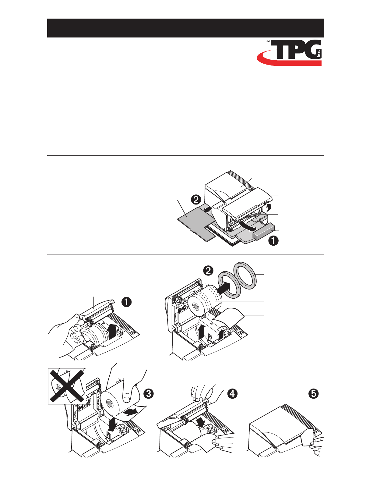
Receipt
Cover
Front Cover
(non-flip model
shown)
Cardboard
Support
Carriage
Foam
Restraint
Receipt
Cover
Starter Roll
Thermal Paper
Paper Roll
Supports
Test Printout
A758 Thermal Receipt and Impact Slip Printer
Setting up the printer
The following instructions will provide a quick reference for setting up the A758 printer.
You will need to refer to the Owner’s Guide or USB Setup Guide downloadable from the
TPG, Inc. web site (http:// www.TPGprinters.com) for specific details for the USB setup
procedures, troubleshooting tips, configuration adjustments, and command
designations. Pages referenced are from the Owner’s Guide, unless noted.
1
Unpack the printer, saving all packing materials for future
shipping or storage (page 13).
2
Load the starter roll of paper (pages 13 & 23).
Setup Guide
Page 2
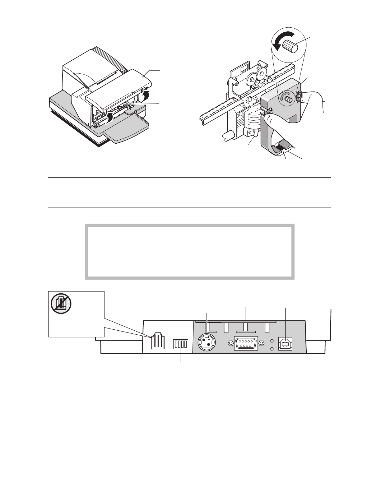
Front Cover
(non-flip model
shown)
Ribbon
Cassette
(Shown in
Position)
Ribbon
Cassette
Knob
Mylar
Shield
Printhead
3
Install the ribbon cassette (page 24).
4
Choose a location for the printer (page 12).
5
Connect the following cables.
When using USB (step “b” below), use caution to ensure
the USB cable is connected to the USB connector
on the back right of the printer and not into the cash
drawer connector that is on the left back of the printer.
a Cash drawer (if your installation includes this feature, page 16).
b 9-pin or 25-pin Serial or USB cable (serial: page 14; USB: page 15).
Note: For USB connection instructions refer to the “A758 Setup Guide with USB”
downloadable from the TPG, Inc. web site (http://www.TPGprinters.com).
c Connect the power cable (page 16).
USB
connector
RS-232C communication
connector
(9-pin shown)
Power
supply
connector
Back of printer
Strain
relief
DIP
switches
Cash drawer
connector
CAUTION:
DO NOT plug the
USB cable here.
Page 3
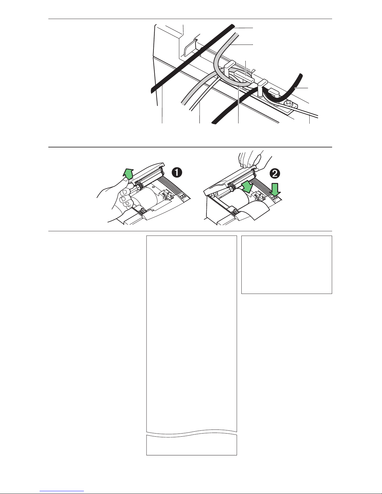
Open
Receipt
Cover
Push and hold
Paper Feed Button
while closing
Receipt Cover
USB
Communication
Cable
To the USB
Connector (when used)
Strain
Relief
Cash Drawer
Cable
Power
Supply
or Adapter
Cable
Cash Drawer
Cable
To the RS-232C
Connector (when used)
RS-232C
Communication
Cable
Print Test and Configuration Menu Sample.
Samples will vary depending on the printer model.
d
Route cables as shown
for your setup configuration
(page 15).
6
Run a diagnostic test to test the printer (page 32).
7
Configure the printer if
necessary (page 33 and
Communication Interface
(page 36) for commands
descriptions and usage).
*** A758 - Diagnostics Form ***
Model number : A758-0000
Serial number : 0000000000
Boot Firmware
Revision : V3.12
CRC : 814C
P/N : 189-1076109C
Flash Firmware
Revision : V4.21
CRC : 19AB
P/N : 189-1076110E
H/W parameters
Flash Memory Size : 512 Mbyte
Flash Logos/Fonts : 64 kbytes
Flash User Storage : 64 kbytes
SRAM Size : 256 kbytes
CPU Clock Freq. : 50 MHz
Head setting : A
Print Density : 100 %
Max Speed : 130 mm/sec
Max Power : 55 W
Alternate Reset : Disabled
Knife : Enabled
Paper Low Sensor : Disabled
MICR : Disabled
Check Flip : Disabled
MICR Dual Pass : Disabled
MICR DC offset : 7F
Slip Position Option : Disabled
Comm. Interface
RX Buffer Size : 4096
Interface type : RS232/USB
Parameters
Baud Rate : 9600
Data Bits : 8
Stop Bit(s) : 1
Parity : NONE
Flow Control : DTR/DSR
Reception Errors : Ignore
Alternate DTR/DSR : Disabled
Resid. Code Pages : 437, 850, 852, 858
860, 863, 865, 866
1252,862,
737
Logo(s) defined : NO
User Char(s) defined : NO
To enter Printer Config Menu :
1) Flip DIP switch #1 down
2) Reset the printer, while holding
the Paper Feed button down
*********
MAIN MENU
**********
*******************************
Select a sub-menu :
- EXIT -> 1 click
- Print Current Configuration -> 2 clicks
- Set Communication Interface -> 3 clicks
- Set Diagnostics Modes -> 4 clicks
- Set Emulation/Software Options -> 5 clicks
- Set Hardware Options -> 6 clicks
Enter code, then hold Button DOWN
at least 1 second to validate
}
Current Printer tallies are
printed after the Diagnostic
information and will vary
per printer use.
Page 4
A758-D110 189-9200390 Rev. B 09/29/04 Printed in USA
Federal Communications Commission (FCC) Radio Frequency Interference Statement Warning
Changes or modifications to this unit not expressly approved by the party responsible for compliance could void the user’s authority to operate the
equipment.
Note
This equipment has been tested and found to comply with the limits for a Class A digital device, pursuant to Part 15 of the FCC Rules. These limits
are designed to provide reasonable protection against harmful interference when the equipment is operated in a commercial environment. This
equipment generates, uses, and can radiate radio frequency energy and, if not installed and used in accordance with the instruction manual, may
cause harmful interference to radio communications. Operation of this equipment in a residential area is likely to cause harmful interference in
which case the user will be required to correct the interference at his own expense.
Information to the User
This equipment must be installed and used in strict accordance with the manufacturer’s instructions. However, there is no guarantee that
interference to radio communications will not occur in a particular commercial installation. If this equipment does cause interference, which can be
determined by turning the equipment off and on, the user is encouraged to contact TPG, Inc. immediately.
TPG, Inc. is not responsible for any radio or television interference caused by unauthorized modification of this equipment or the substitution or
attachment of connecting cables and equipment other than those specified by TPG, Inc. The correction of interferences caused by such
unauthorized modification, substitution or attachment will be the responsibility of the user.
In order to ensure compliance with the Product Safety, FCC and CE marking requirements, you must use the power supply, power cord, and
interface cable which are sold for use with this product or which meet the following parameters:
Power Supply
UL Listed (QQGQ), Class 2 power supply with SELV (Secondary Extra Low Voltage), non-energy hazard output, limited energy source, input rated
100-240 Vac, 1.5/0.8 A, 50/60 Hz, output rated 24 Vdc, 2.3 A for 55 watt unit; 100-240 Vac, 2.0A, 50/60 Hz, output rate 24 Vdc, 3.125 A for 75 watt
unit.
Use of this product with a power supply other than the TPG, Inc. power supply will require you to test the power supply and TPG, Inc. printer for
FCC and CE mark certification.
Communication Interface Cable
A shielded (360 degree) interface cable must be used with this product. The shield must be connected to the frame or earth ground connection or
earth ground reference at EACH end of the cable.
Use of a cable other than described here will require that you test the cable with the TPG, Inc. printer and your system for FCC and CE mark
certification.
Power Cord
A UL listed, detachable power cord must be used. For applications where the power supply module may be mounted on the floor, a power cord with
Type SJT marking must be used. For applications outside the US, power cords which meet the particular country’s certification and application
requirements should be used.
Use of a power cord other than described here may result in a violation of safety certifications which are in force in the country of use.
Industry Canada (IC) Radio Frequency Interference Statement
This Class A digital apparatus meets all requirements of the Canadian Interference-Causing Equipment Regulations.
Cet appareil numérique de la classe A respecte toutes les exigences du Règlement sur le matériel brouilleur du Canada.
Voluntary Control Council for Interference (VCCI) Radio Frequency Interference Statement
This is a Class A product based on the standard of the Voluntary Control
Council for Interference by Information Technology Equipment (VCCI). If this
equipment is used in a domestic environment, radio disturbance may arise.
When such trouble occurs, the user may be required to take corrective actions.
Disclaimer
Information in this document is subject to change without notice. Consult your TPG, Inc. sales representative for information that is applicable and
current. TPG, Inc. reserves the right to improve products as new technology, components, software, and firmware become available.
No part of this document may be reproduced, transmitted, or translated in any form or by any means, electronic or mechanical, for any purpose
without the express written permission of TPG, Inc.
Copyright
Copyright © 2004 by TPG, Inc.
950 Danby Road, Ithaca, New York 14850, USA. All rights reserved. Printed in USA. Confidential, Unpublished. Property of TPG, Inc.
Trademarks
TPG, Inc.™ is a trademark of TPG, Inc.and its subsidiaries.
Microsoft, Windows NT are registered Trademarks of Microsoft Corporation in the U.S.A. and/or other countries.
Inside Out Networks, Inside Out, EPIC, and Edgeport are trademarks of Inside Out Networks.
All other trademarks and registered trademarks are the property of their respective holders.
Patents
Made under one or more of the following U.S. patents: 4886381, 5579043, 5613787, 5651624, 5713678, 5752779, 5789916, 5800080, 5879090,
5887999, 5975776, 6027266, 6085973, 6089450, 6129465, 6155483, 6404452, 6,486,902, 6,504,331, 5,749,277, 6,722,754, 6,739,773, 6,784,909.
Other U.S. and International patents pending.
Web Site
http://www.TPGprinters.com
 Loading...