

Page 1
!
1!
www.tpcdental.com!www.tpcdental.com!
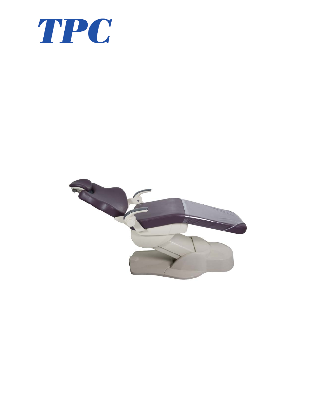
Laguna!2000!
Electromechanical!
Patient!Chair!
!
Installation,!Operation!&!User!Manual!!
TPC!
851 S. Lawson St.
City Of Industry, CA 91748
P626-810-4337 Fax 626-810-4245
Page 2

!
2!
www.tpcdental.com!www.tpcdental.com!
Table!on!Contents:!!! ! ! ! ! ! ! Page!
GENERAL'INFORMATION''' ' ' ' ' ! 3!
! Installation!and!coordination!! ! ! ! 5!
Motion!Limit!Controls! ! ! ! ! ! 10!
! Operation!instructions! ! ! ! ! ! 11!
! Overview!of!controls!! ! ! ! ! ! 12!
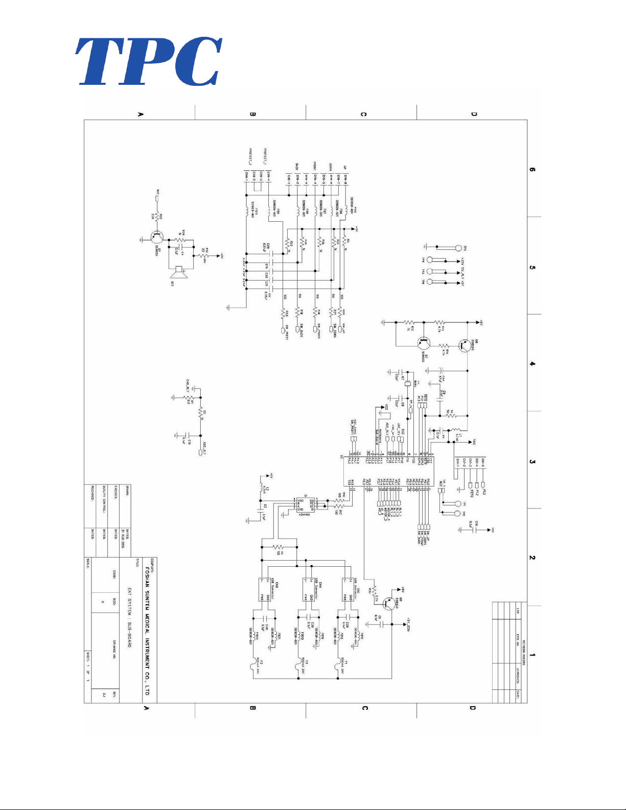
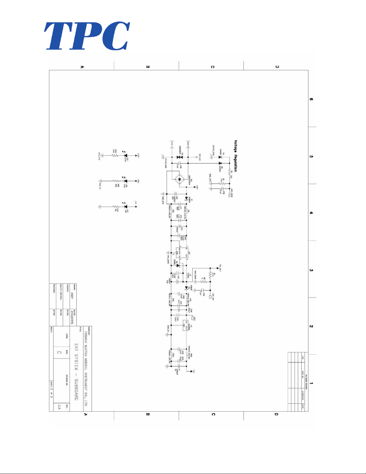
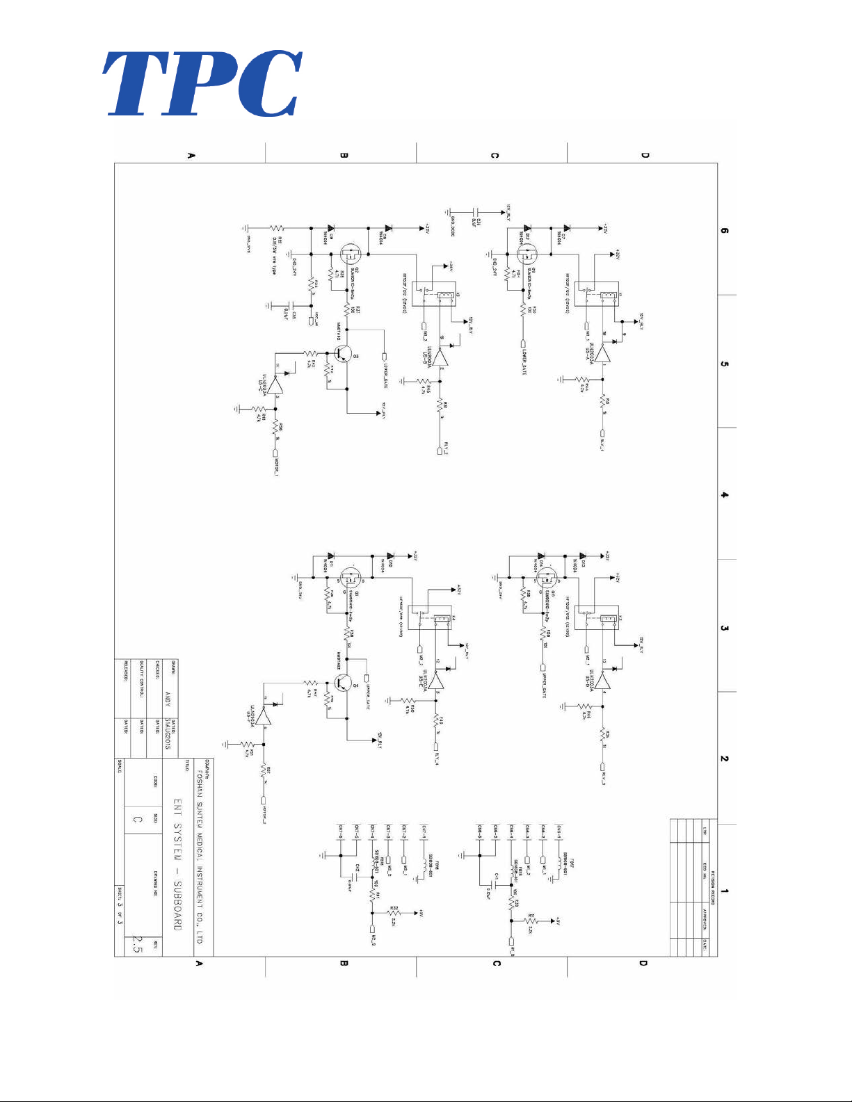
! Main!PCB!Board!!! ! ! ! ! ! ! 14!
CLEANING'&'DISINFECTING'GUIDE' ' ' ' 18!
Warranty'' ' ' ' ' ' ' ' ' ! 19!
TROUBLE'SHOOTING'GUIDE' ' ' ' ' 20!
!
!
!
!
!
!
!
Page 3
!
3!
www.tpcdental.com!www.tpcdental.com!
GENERAL!INFORMATION!
!
!!!!!!!!!!!!!!
!
! ! ! ! ! ! !
!
!
! !
!
!
! ! ! ! !
!
!
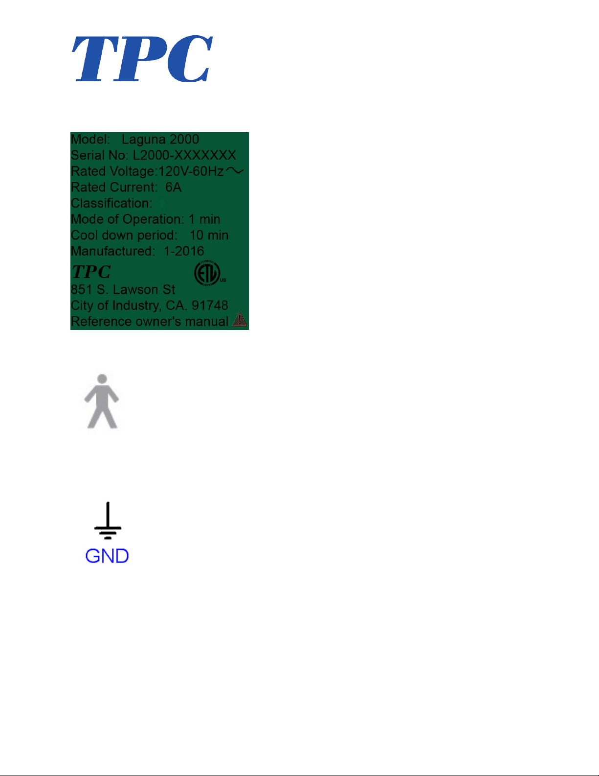
The'dental'chair'is'marked'
with'a'product'identification'
label'including'manufacture,'
serial'number'and'date'of'
manufacture.'This'label'is'
located'on'the'front'lower'left'
cover'under'the'seat'cushion.''
The'dental'chair'is'marked'with'a'
Risk'Class'symbol.'This'lab el'is'
located'on'the'front'of'the'd en ta l'
chair'base'next'to'the'main'
power'switch.''
The'dental'chair'is'marked'with'a'
main'electrical'grounding'point'
symbol.'This'label'is'located'on'
the'front''left'side'of'the'dental'
chair'steel'base'frame,'under'the'
plastic'cover.''
Page 4

!
4!
www.tpcdental.com!www.tpcdental.com!
!
!
!
!
!
!
Transportation!/!Storage!Information!
• Do!not!store!the!dental!chair!in!temperatures!exceeding!130!degrees.!!
• Do!not!store!the!dental!chair!on!its!side.!Always!store!upright!on!pallet.!
• Do!not!stack!more!than!5!packaged!chairs!at!a!time!on!top!of!each!other.!!
• Use!approved!pallet!jack!or!forklift!to!move!the!dental!chair.!!
• Do!not!attempt!to!move!stacked!dental!chairs.!!
• Only!store!the!dental!chair!in!dry!cool!place.!!
!
!
!
!
!
!
!
!
!
The'dental'chair'is'marked'with'a'
main'electrical'grounding'point'
symbol.'This'label'is'located'on'
the'front''left'side'of'the'dental'
chair'steel'base'frame,'under'the'
plastic'cover.''
The!fuse!is!a!6!amp!time!lag,!Fuse,!3AG,!1!
1/4"!L!x!1/4"!Dia.!(31.8mm!x!6.4mm)!
The'dental'chair'is'marked'with'a'
fuse'label'symbol.'This'labe l'is'
located'under'the'pump'cover'on'
the'front'left'side'of'the'chair'
frame.''
Page 5
!
5!
www.tpcdental.com!www.tpcdental.com!
Laguna!2000!Installation!Instructions!
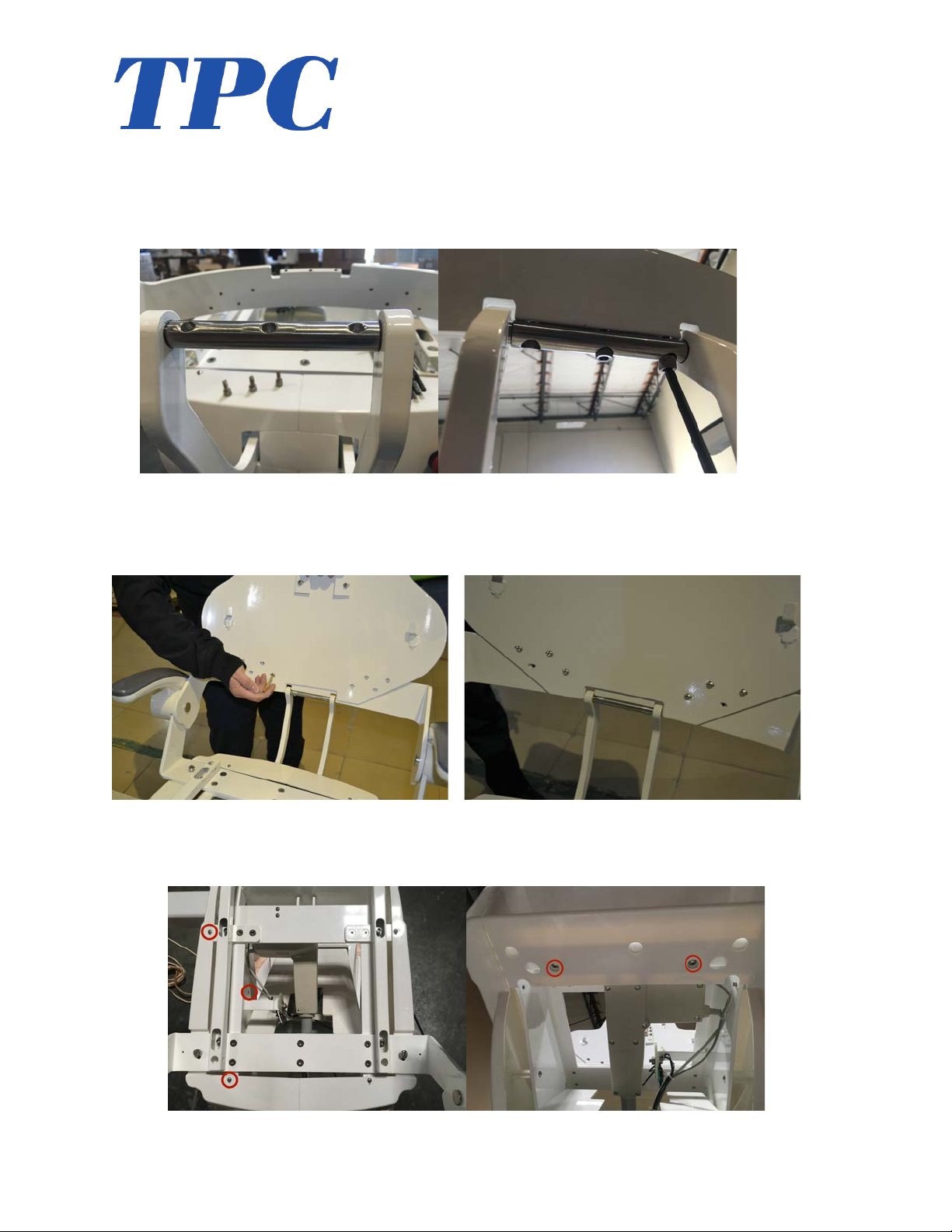
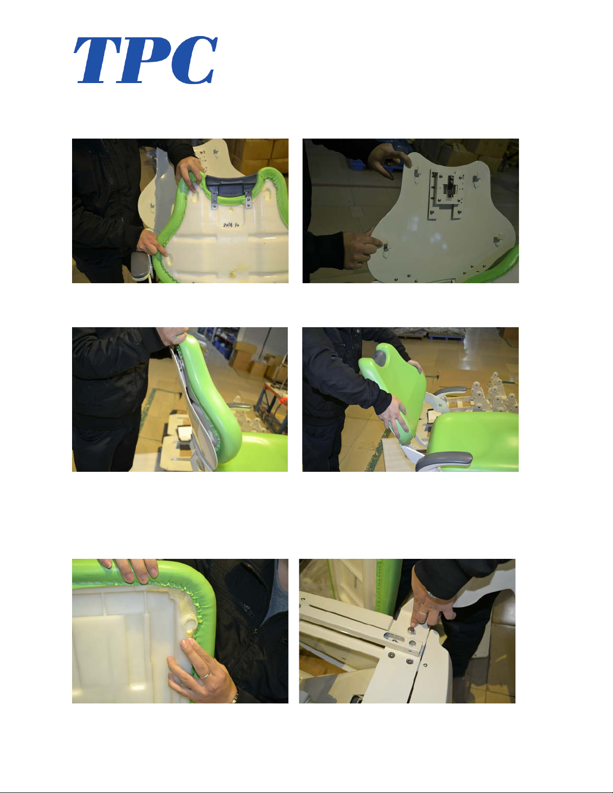
1. Con nect!the!backrest!support!arm!to!the!backrest!bracket.!Use!
the!three!supplied!Allen!screws.!!
!
2. In stall!ch air!ba ckre st!as!sh ow n !in!the!im ag es!be low .!Us ing!th e!
8!Allen!screws,!secure!the!backrest!frame!in!place.!!
!!! !
3. Remove!the!side!cover!where!chair!bracket!is!to!be!installed.!
You!will!also!need!to!remove!the!lower!front!panel!shown.!!
!
Page 6
!
6!
www.tpcdental.com!www.tpcdental.com!
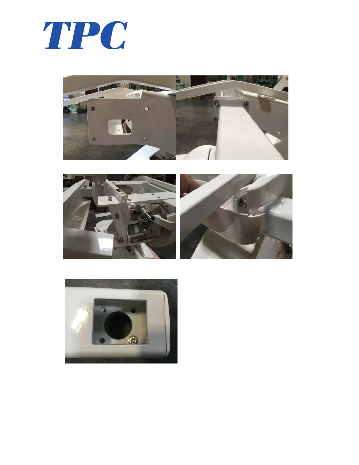
4. In stall!th e!cha ir!brack et!as !shown,!use!the!included!4!Allen!
screws.!!
!
5. Re!install!the!chair!side!cover!once!the!bracket!is!installed.!!
!! !
6. Mount!the!Cup!to!the!chair!bracket.!!
!!!!!!!!!!! !
!
!
Page 7
!
7!
www.tpcdental.com!www.tpcdental.com!
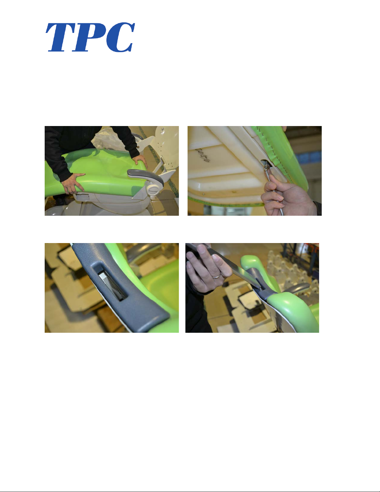
7. In stall!th e!backrest!cushion!onto!the!frame.!Make!sure!you!
align!the!mounting!points!before!sliding!into!place.!!
!!!! !
!
!!!! !
8. In stall!th e!sea t!cush ion!o nto!th e!sea t!fram e.!M ake !sure!y ou!
align!the!mounting!points!before!sliding!into!place.!!
!
!!! !
Page 8
!
8!
www.tpcdental.com!www.tpcdental.com!
!
!
9. Once!you!have!confirmed!the!seat!cushion!is!in!place!slide!it!
toward!the!backrest!to!lock!it!in!place.!!Secure!the!seat!cushion!
in!place!using!the!two!supplied!Allen!screws.!!
!!!! !
10. Insert!the!headrest!stem!as!shown.!!
!!! !
!
!
!
!
!
Page 9
!
9!
www.tpcdental.com!www.tpcdental.com!
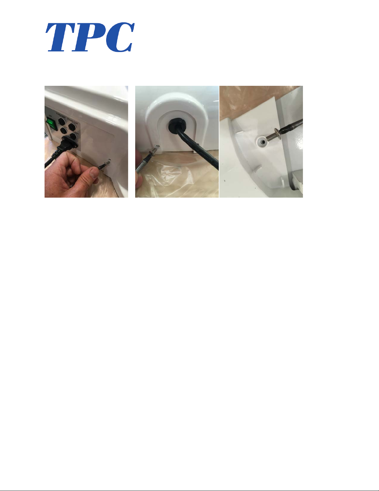
11. Install!the!Pump!cover!and!rear!base!covers.!Use !the!
supplied!screws!to!secure!the!covers!in!place.!!
!!! !
!
!
!
!
!
!
!
!
!
!
!
!
Page 10
!
10!
www.tpcdental.com!
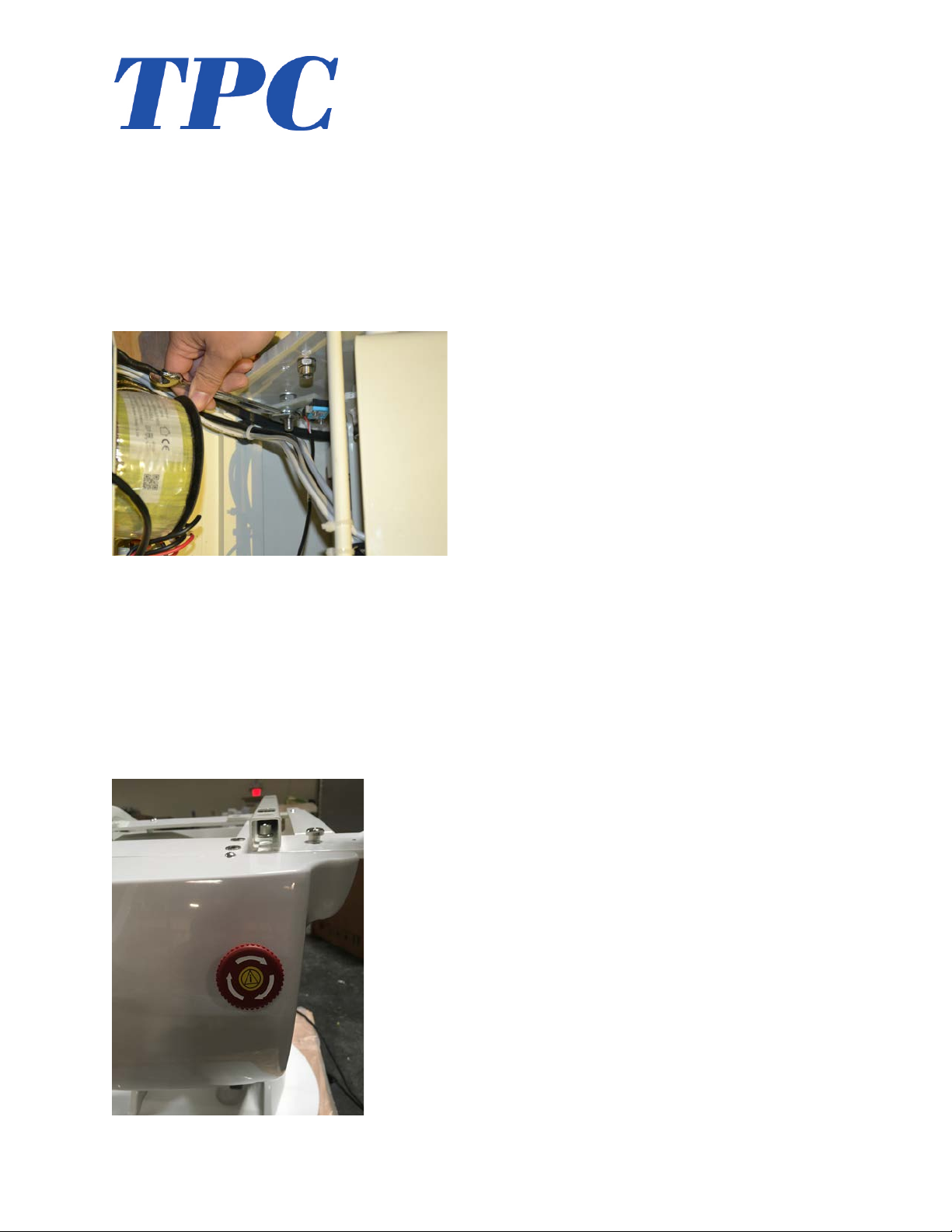
Adjusting!the!chair!limits!
1. To!adjust!the!seat!height!limit,!loosen!nut!as!shown.!Once!the!
nut!is!not!secured,!you!can!adjust!the!switches!position!to!
activate!at!a!different!height.!Once!adjusted,!secure!the!
adjusting!nut.!!
!
!
Emergency'Stop'Button'
The!dental!chair!possesses!an!emergency!stop!button.!In!the!event!
that!you!need!to!stop!the!chair!movement!push!in!the!stop!sw itch.!
To!disengage,!turn!clockwise.!
!
Page 11
!
11!
www.tpcdental.com!
!
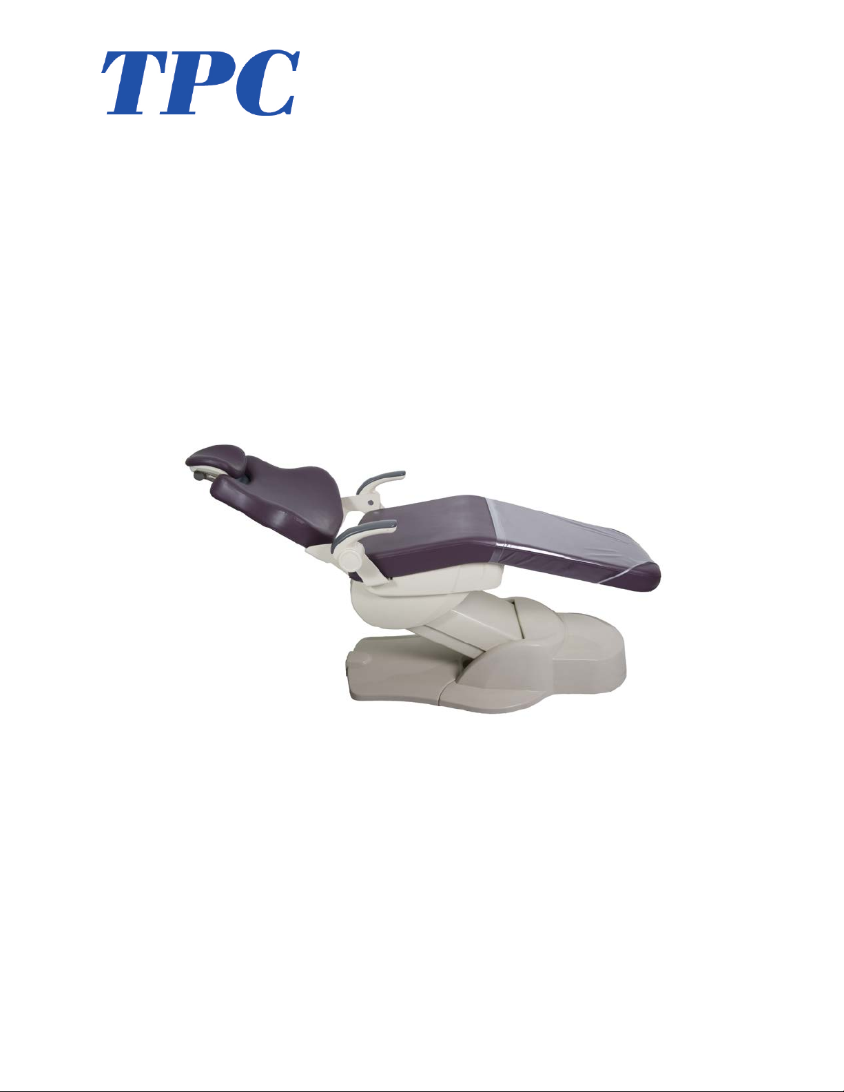
Laguna!2000!
Electromechanical!Patient!Chair!
Operating!instructions!
!
!
!
!
!
!
!
!
!
!
Page 12
!
12!
www.tpcdental.com!
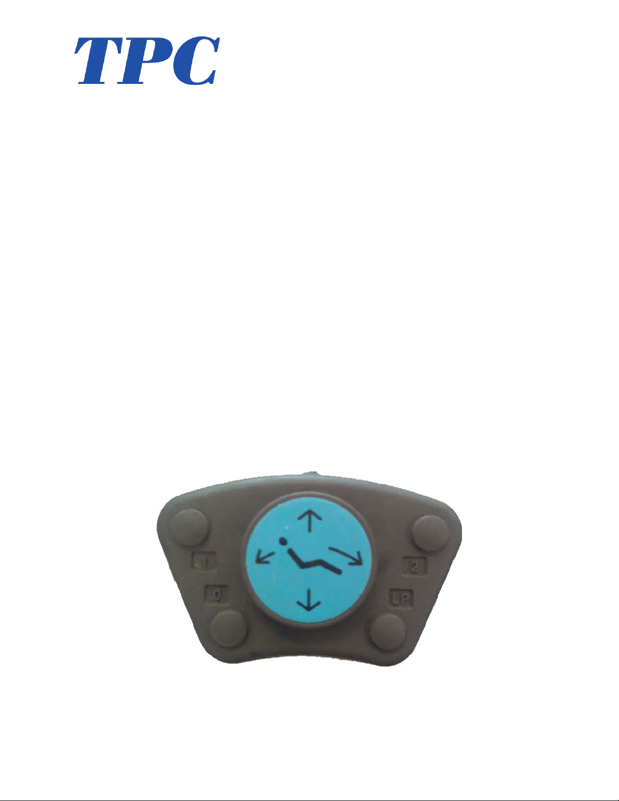
Overview!of!Foot!controls!!
Overview!of!foot!control!operations!!
1. Seat Height Adjustments
- To!raise,!press!down!on!upper!area!of!the!foot!control!disc.!
- To!lower,!press!down!on!the!lower!area!of!the!foot!control!disc.!
!
2. Backrest Adjustments
- To!raise,!press!down!on!right!side!of!the!foot!control!disc.!
- To!recline,!press!down!on!left!side!of!foot!control!disc.!
!
3. Preset Operation
- Momentarily!press!pre!set!switch!(#1,!or!#2)!on!the!foot!control.!
!
4. Automatic Return
Momentarily press 0 switch on foot control to activate chair to return to normal position.
5. LP Program
To program a preset, move chair to desired position. Press LP, then Press the memory position 1
or 2. Then Press LP again, this will be accompanied by a longer tone when complete.
!
!
!
!
!
!
Chair!Base!up!!
Preset!1!
Preset!2!
Chair!Base!Down!
Back!Up!
Program!!
Page 13
!
13!
www.tpcdental.com!
'
Safety'Plate!
Safety plate is provided in the backrest cover to stop motion of chair when object is accidentally
caught underneath.
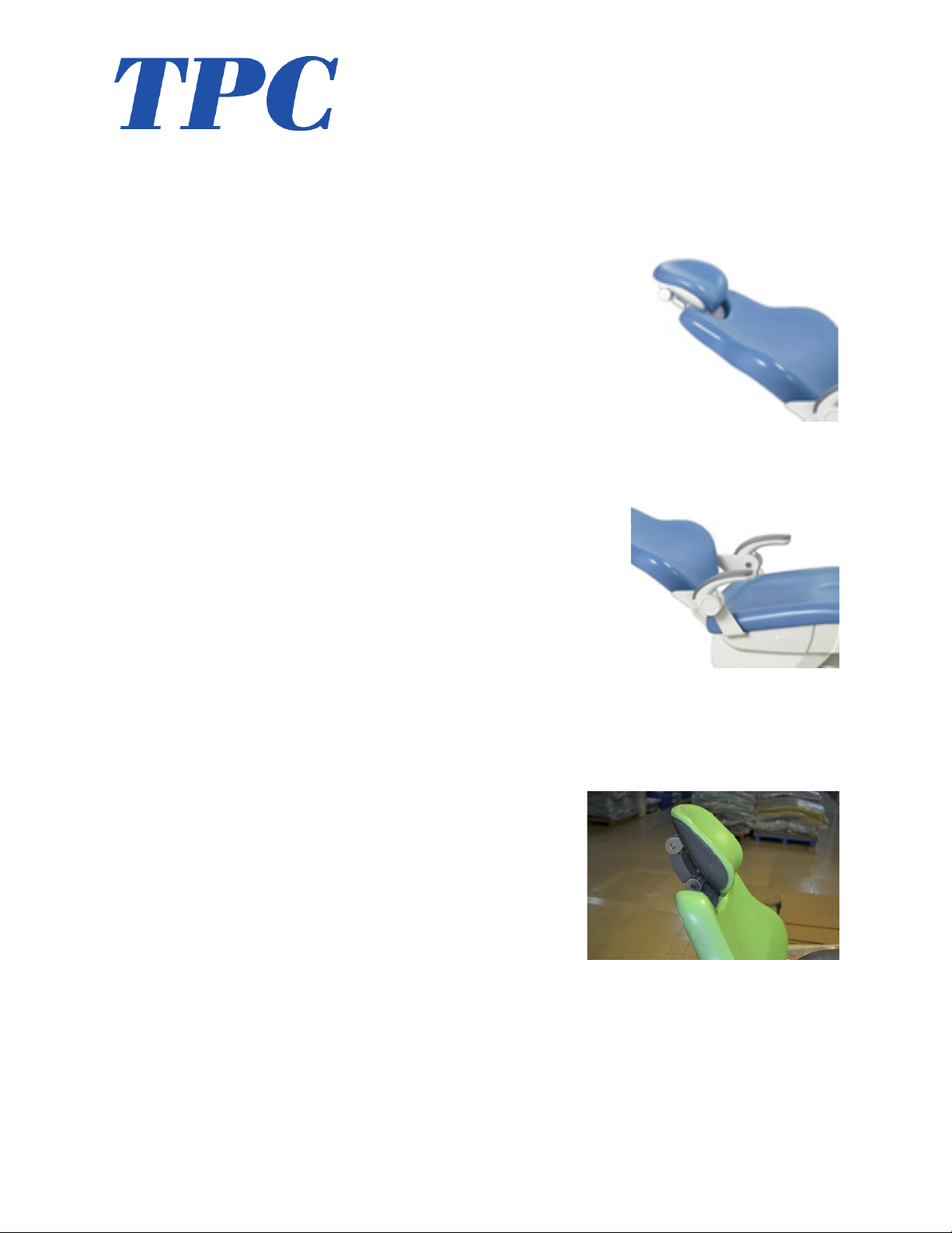
7.''Armrest'Rotation!
Either armrest can be rotated upward by grasping the end portion of armrest, pulling upward.
8.''Headrest'Adjustments'
Height!of!headrest!can!be!adjusted!simply!by!pulling!headrest!up!or!down!due!to!friction!mount!
incorporated!in!back re st .!!An g le !of!a rt iculating!headrest!can!be!changed!by!releasing!slide!bar!on!
headrest!stem'
!
!!
!
Page 14
!
14!
www.tpcdental.com!
!
Page 15
!
15!
www.tpcdental.com!
!
Page 16
!
16!
www.tpcdental.com!
!
Page 17
!
17!
www.tpcdental.com!
!
Page 18

!
18!
www.tpcdental.com!
Laguna 2000 Patient Chair – Care and Maintenance
No maintenance is required except normal care and cleaning.
Clean vinyl upholstery and plastic components with mild soap and water.
Barrier covers should be used on chairs for asepsis.
Surface disinfecting chemical will eventually cause some discoloring of upholstery.
Suggested Disinfectant Application
Clean dirt and stains with mild soap and water.
Moisten an applicator with disinfectant; mildly wipe the material with the disinfectant.
Do not allow the disinfectant to soak in or dry on the surface; wipe off with soap and water.
PLEASE KEEP LIQUIDS AWAY FROM ELECTRICAL CONNECTIONS!
Most electrical control switches ARE NOT hermetically sealed.
When a switch gets wet, it can self-activate, or perhaps short out and damage other system
components. Keep switches dry. Avoid costly equipment damage or failure. Avoid downtime by
following these guidelines:
Please DO NOT spray disinfectants directly AT OR INTO electrical switches and controls.
Simply spray these solutions onto a cloth and wipe down the control surfaces. Be careful not to
saturate the cloth.
• Any action not recommended by the manufacture may cause risk of injury or shock!
FOR ADDITIONAL INFORMATION CONTACT YOUR TPC DEALER
Page 19

!
19!
www.tpcdental.com!
TPC 5 YEAR LIMITED WARRANTY
Warranty Information
All of our products sold are guaranteed to be free from defects in workmanship and materials for
a 1 year from date of purchase, unless otherwise stated. TPC will repair or replace any defective
part at no charge. TPC will not be responsible for labor charges or shipping charges to / from the
TPC facility. This guarantee does not cover normal wear or stains on surface finish. The
guarantee does not cover damage resulting from improper installation, misuse or accidents
incurred in shipping and handling. All claims against the freight carrier must be initiated at the
time the damaged items are received. The claim is the responsibility of the customer. We are
improving our products on a continuous basis. We reserve the right to make modifications
without the need for prior notification and are not obliged to modify previously manufactured
items. Main drive motors parts are covered under the 5 year warranty. Main chair PCB,
transformer are also covered under a 5 year warranty. Major cast components are covered under
the TPC limited 5 year warranty. Upholstery, arm rests and any plastic components are covered
under a 1 year warranty. Only authorized service technicians should attempt to service TPC
equipment. Service performed by any unauthorized technicians may result in a voided warranty.
Page 20

!
20!
www.tpcdental.com!
Laguna 2000 Chair Troubleshooting
Problem
Cause
Solution
Dental Chair does not move
up or down. Chair makes no
sound.
No power
Blown fuse
Power switch off
Blown transformer
Check power source
Check fuse
Check power switch
Check transformer voltage
12vac
Dental Chair will not move,
but makes a beep sound when
controls are pressed
Safety switch plate
Limit switch memory erased
Check safety plate
Re-program limit switches.
Refer to motions of limit
controls
Chair makes noise when
motor is running. Squealing
Damage to drive extension
Check drive extension for
damage
Dental Chair does not go low
or high enough
Limit switch moved or is
damaged
Adjust limit switch or replace
is damaged
Unable to program pre set
position 1, 2 and 3
Press SET to program presets.
Button may be damaged
Press Set. Replace set button
on touchpad.
My chair is on but there is no
control out of the touch pad
Touch pad is not connected
Touch pad is burnt out
Connect touch pad
Replace touch pad
My head rest does not stay in
the position that I put it in
Set screws in backrest are
loose.
Tighten set screws
Chair arm rest moves very
Easley.
Screw is loose that holds
assembly together
Tighten screw
Page 21

!
21!
www.tpcdental.com!
Laguna 2000 Chair Limitations
• Don’t exceed the maximum weight capacity of 600 lbs or damage may occur.
• Don’t let more than one patient sit in the chair at one time.
• Don’t stand anywhere on the dental chair.
• Don’t operate the dental chair around any flammable liquids.
• Don’t exceed the maximum mode of operation time “3 min”.
• Keep liquids away from electrical components.
!
Page 22
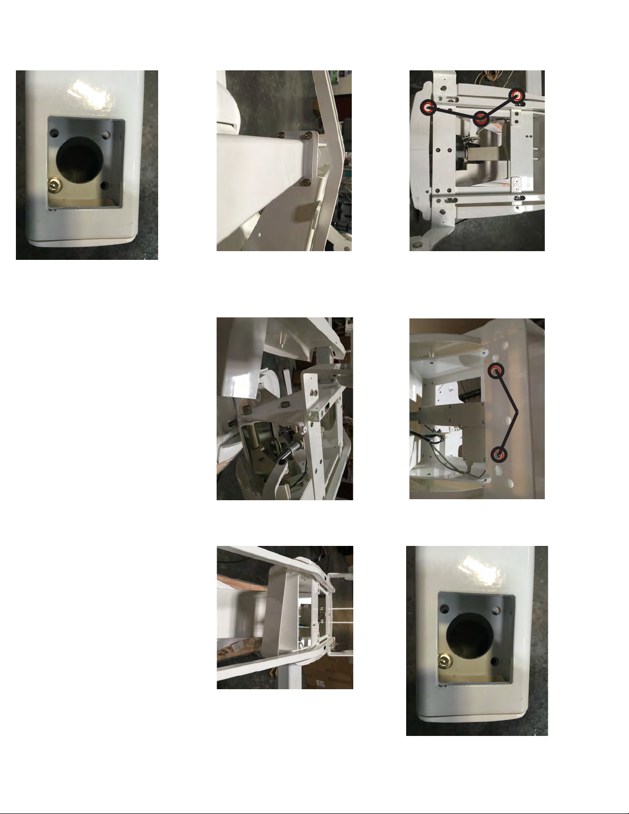
bracket as shown. Repalce screws
4. Install bracket onto the dental chair. 5. Install the side cover over the
1. Remove the three screws shown. 2. Remove the front cover
Laguna 2000 Chair Bracket Installation procedure
7. Re install the chair bracket cup to the bracket.
6. Install Front cover
3. Remove the bracket cup from the chair bracket.
Page 23
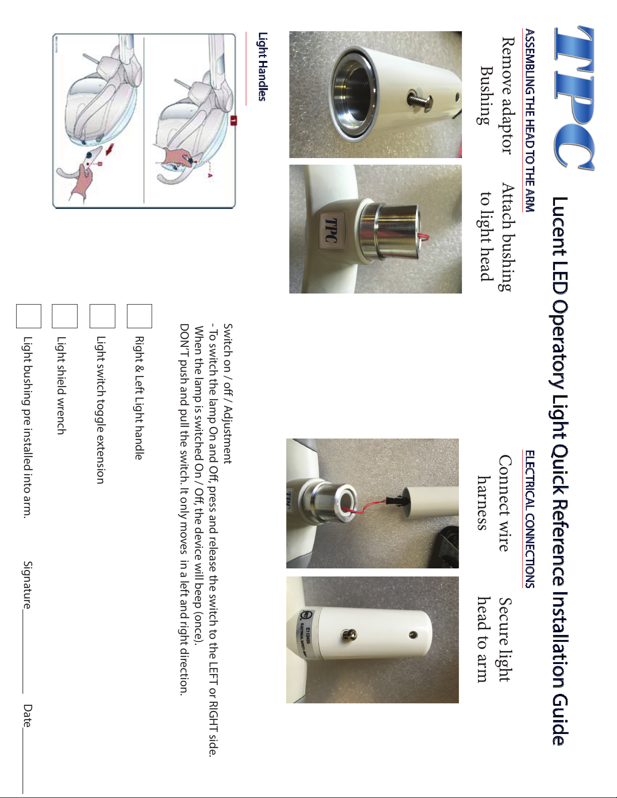
Lucent LED Operatory Light Quick Reference Installation Guide
ASSEMBLING THE HEAD TO THE ARM ELECTRICAL CONNECTIONS
Light Handles
Remove adaptor
Bushing
Attach bushing
to light head
Connect wire
harness
Secure light
head to arm
Switch on / o / Adjustment
- To switch the lamp On and O, press and release the switch to the LEFT or RIGHT side.
When the lamp is switched On / O, the device will beep (once).
DON’T push and pull the switch. It only moves in a left and right direction.
Right & Left Light handle
Light switch toggle extension
Light shield wrench
Light bushing pre installed into arm. Signature______________ Date___________
Page 24
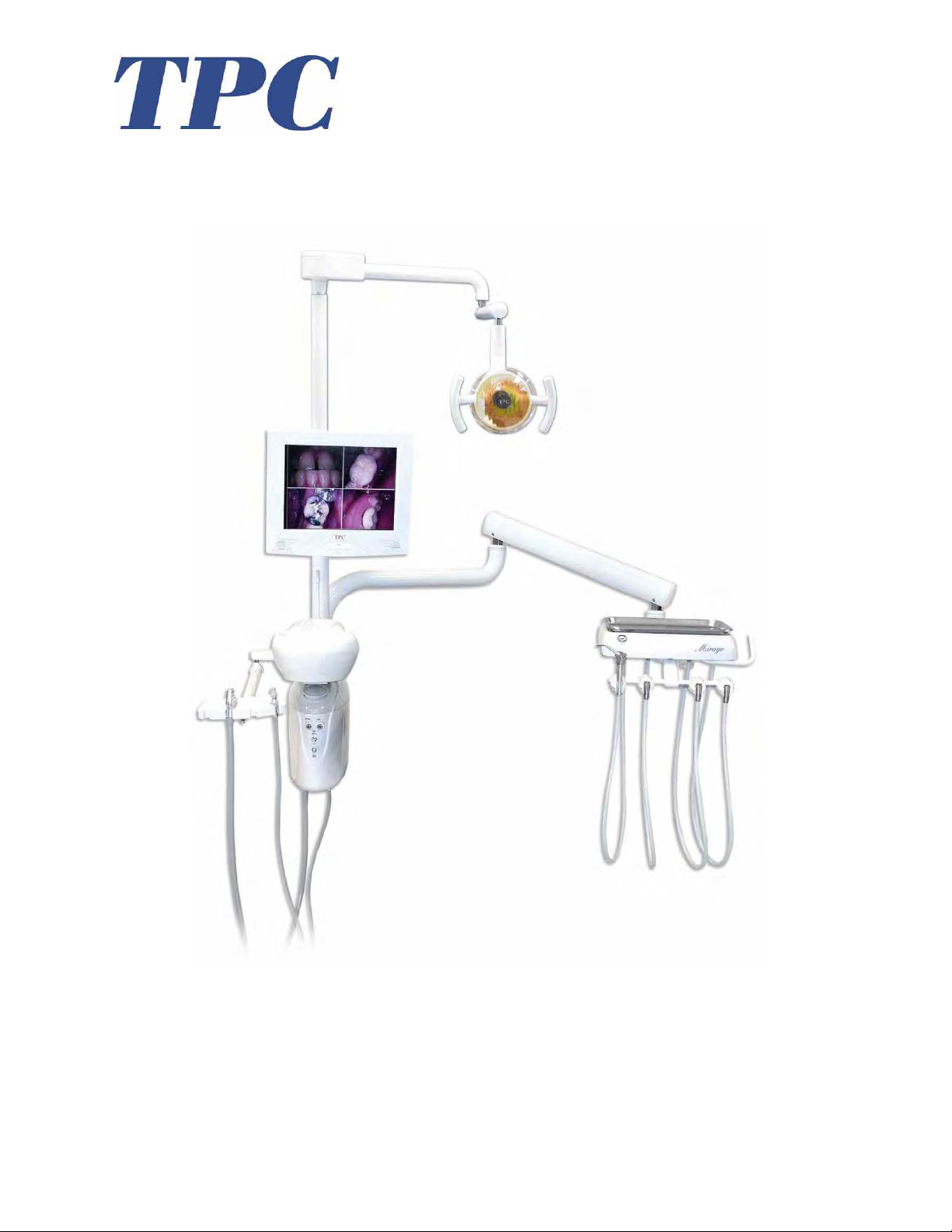
Mirage Dental Delivery Unit
Model 2000 / 2015 Installation Instructions
TPC
851 S. Lawson St.
City Of Industry, CA 91748
P626-810-4337 Fax 626-810-4245
1
www.tpcdental.com
Page 25

Table on Contents: Page
GENERAL INFORMATION
Unpacking and Inventory 3
Installation and coordination 4
Optional Cuspidor Installation 10
Cuspidor Plumbing Connections 11
Junction Box Connections 12
Post Mount Utility Center Adjustments 13
Pressure Adjustments / Tension Screws 13
Delivery Head / Tilt Adjustments 14
Tubing / Connections 15
www.tpcdental.com
2
Page 26

Unpacking and Inventory
Each Mirage delivery unit will contain the following items in each box.
1. Flex arm box. This is the largest box that you will receive with the delivery unit.
• Delivery unit flex arm
• Assistance arm
• Light post
• Foot control
• Stainless steel tray
• Cosmetic beauty ring
2. Post mount utility center
• Utility center
• Junction box (frame & cover)
• Master controls attached to the umbilical
• Misc beauty rings and quick connects
• HEV/SE valves with tubing
• Water Bottle (750 ml)
3. Optional 2000-C Cuspidor
• Cuspidor
• Cup fill spout
• Bowl rinse spout
• Cuspidor bowl strainer
• 2 fastening screws
• If at any time you have questions regarding
your installation please dont hesitate to
contact TPC toll free @ 800-560-8222 or via Email @ [email protected]
3
www.tpcdental.com
Page 27
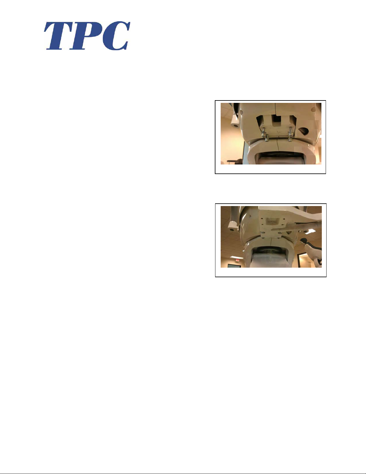
Installation Instructions.
1. Locate the four mounting bolts that were included with your dental chair. These bolts are
attached to all model 4000 dental chairs. See image below for the location.
2. Remove the mounting bolts and mount the bracket as shown in the image below.
3. Leveling Chair bracket.
• The chair bracket has a total of 8 set screws.
• Use the lower set screws to adjust the PMU left, right, front and back. This will make
large adjustments to the tilt of the post that is inserted into the bracket cup.
• Use the upper set screws to make fine adjustments and lock the post in place.
• Once the post is level you may fasten the set screws tightly to ensure the post stays level.
If your post is not level your unit will not be level and the flex arm will drift.
4
www.tpcdental.com
Page 28
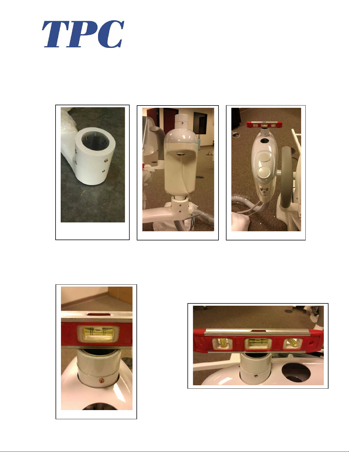
4. Loosen the 8 leveling set screws, and then place the PMU (Post mount utility center) in
the cup of the chair bracket. Figure1 Shown in the image below. Center the mounting
post in the cup. Also verify if the PMU is aligned straight with dental chair armrest. Then
proceed to tighten the set screws.
5. Verify the PMU is level before tightening the set screws on chair bracket. There are 8 set
screws that will be used for leveling. If the PMU is not level the unit arms may drift.
Small adjustments to the set screws will level the PMU. Level the PMU in the following
directions. (left to right and front to back).
5
www.tpcdental.com
Page 29
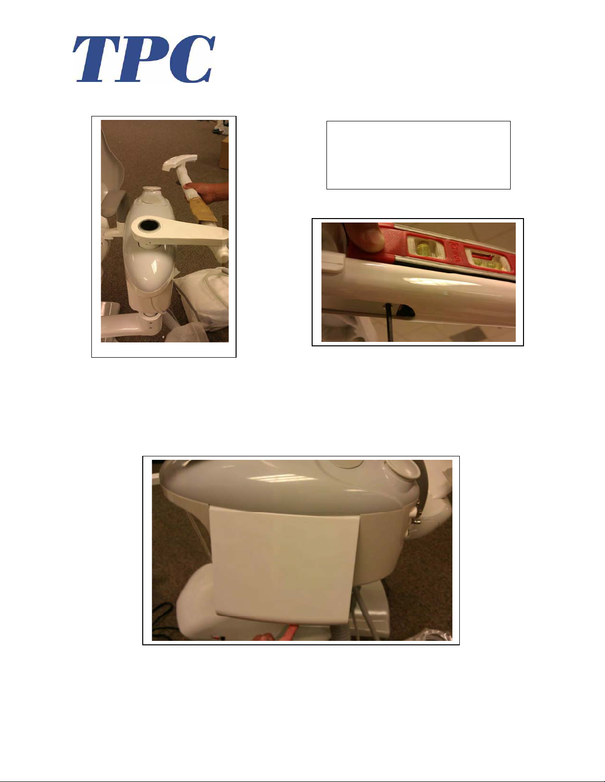
6. Place the assistant's suction arm on the PMU as shown in the image below. If the arm is
not level use the leveling screw shown below (right) to adjust its angle.
Turning this screw clockwise will raise
the angle of the arm. Turning counter
clockwise will lower the angle of the
arm.
7. Remove the PMU side cover. To remove it, pull on the lower lip to detach its magnetic
connection. Place it out of the way to ensure it does not get damaged. This side cover will
remain detached until the end of the installation.
6
www.tpcdental.com
Page 30
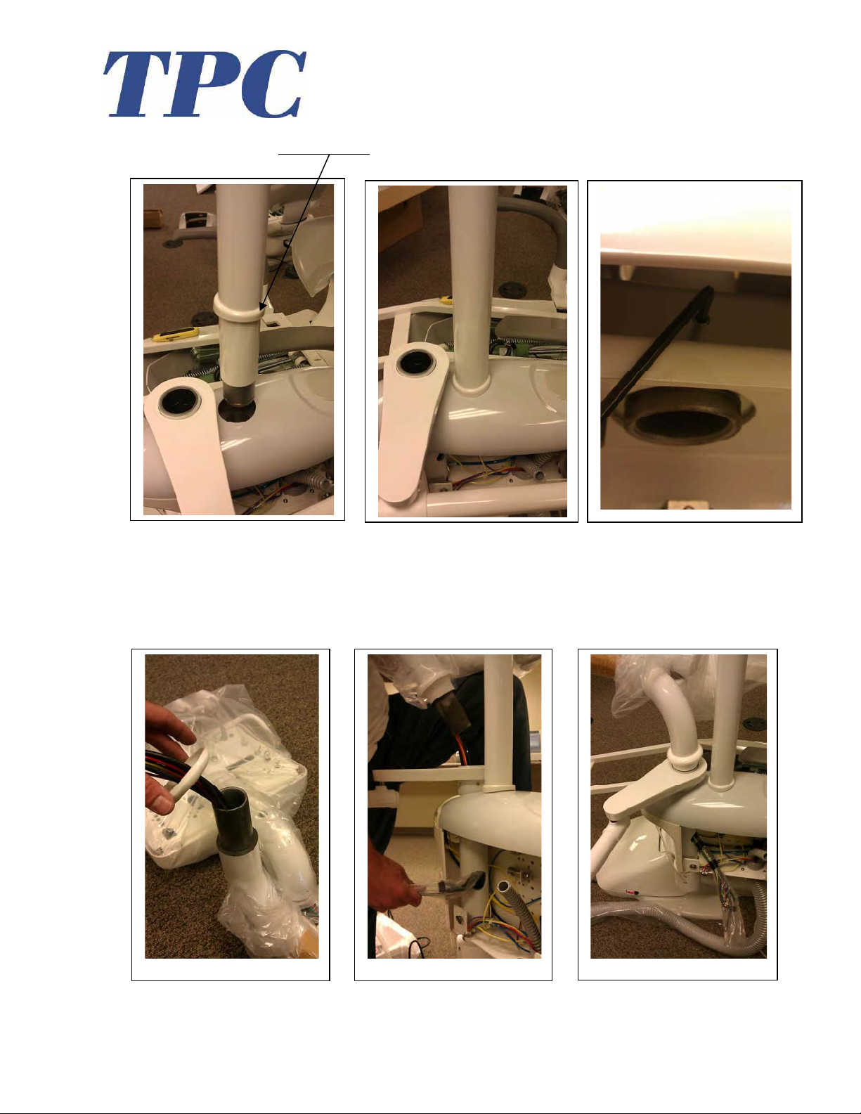
8. If you are installing a post mounted light insert it as shown in the images below. Make
sure you place the cosmetic ring over the light post before inserting. Tighten the set screw
to secure the light post in place.
9. Take the delivery unit flex arm out, and place the additional cosmetic ring on it as shown
below. Once in place, take all lines and feed it through the bushing assembly as shown.
Verify that the arm seats completely down in the bushing assembly. Lower the cosmetic
ring to cover the seam between the assistant's arm and the delivery unit flex arm.
7
www.tpcdental.com
Page 31
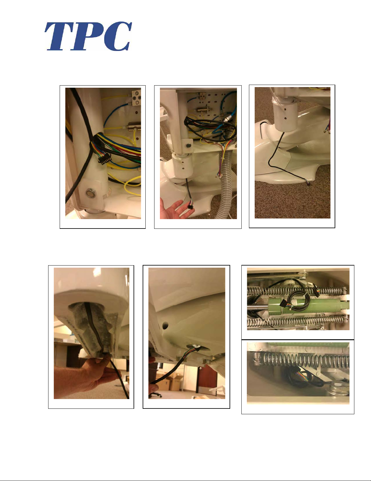
10. You may now remove the plastic from the bundle of tubings that you fed through in the
previous step. Take the touch pad wire shown below and feed it through the chair bracket
as shown.
11. Route the touch pad cable along the chair bracket channel. Then feed it through the "cut
out" in the plastic shroud. Connect the touchpad wire and place it aside as shown.
8
www.tpcdental.com
Page 32
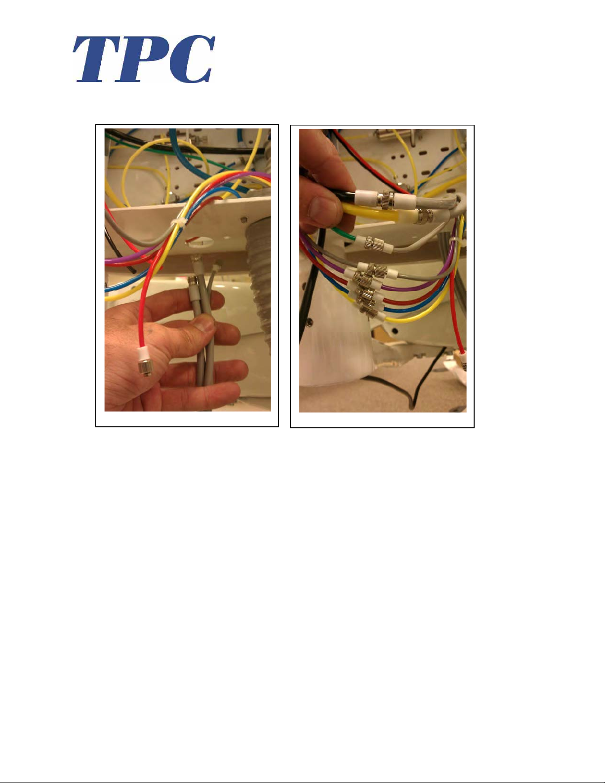
12. Take the delivery systems foot control and feed it through the bottom of the PMU. Make
the following connections from your foot control to the tubing within the PMU side box.
13. Tubing connections
• Grey female from foot control to Black supply to the flex arm.
• Grey male from foot control to Yellow supply from Umbilical.
• Green female from foot control to Green male from the flex arm.
• Grey female from umbilical to Grey male from the flex arm.
• Purple female from umbilical to Purple male from the flex arm.
• Dark Red female from umbilical to Dark Red male from the flex arm.
• Blue female from umbilical to Blue male from the flex arm.
• Yellow female from umbilical to Yellow male from the flex arm.
• You will have two spare lines available the event of a tubing failure.
14. There is also two additional lines that will be left unused if you are not installing the
optional 2000-C cuspidor. One large water supply line and a small yellow air supply line
that has a cap on it.
9
www.tpcdental.com
Page 33
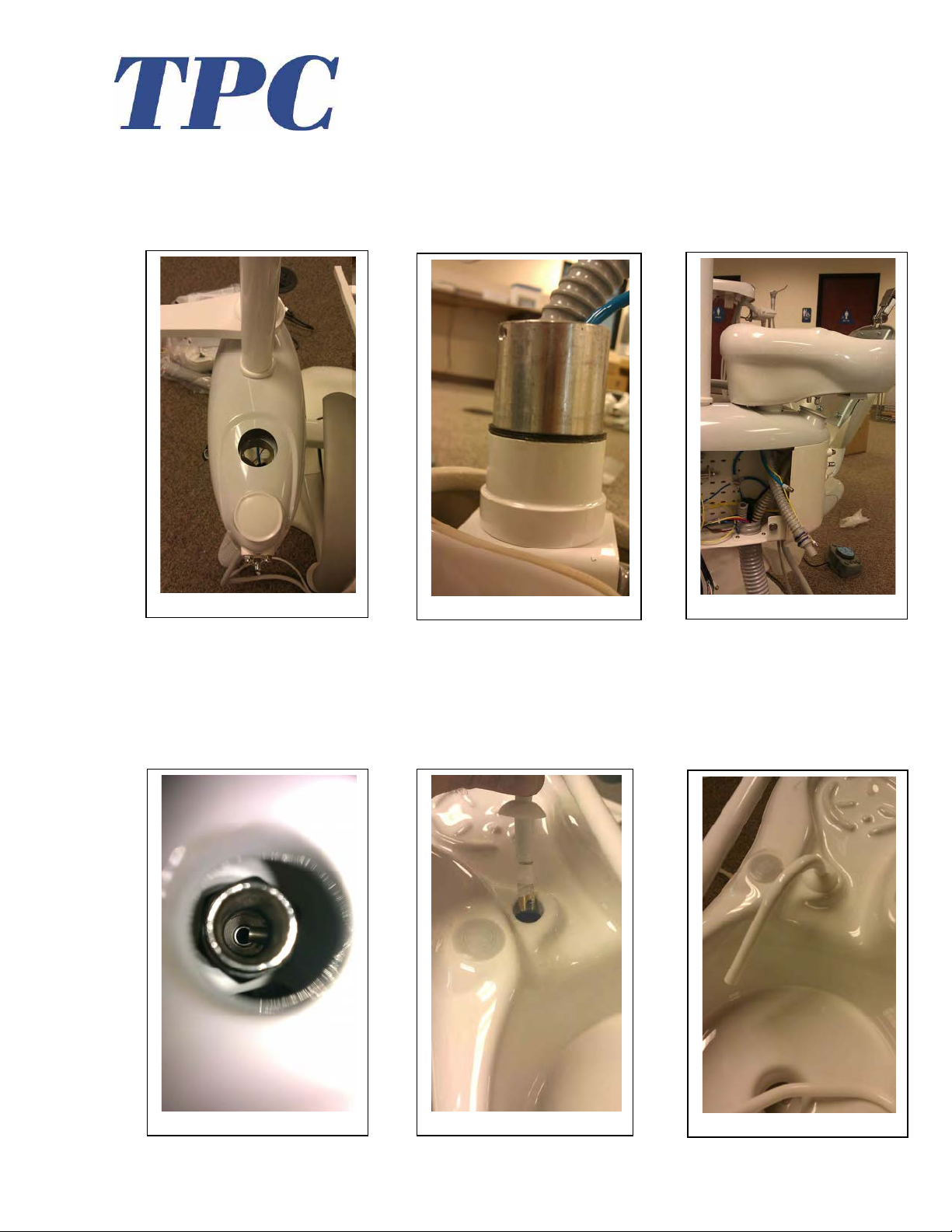
Optional Cuspidor Installation
If you are installing the optional 2000-C cuspidor, remove the Cuspidor housing cover as
shown. To install the cuspidor, slide the cuspidor into the cuspidor bushing housing.
Make sure the cuspidor is completely seated in the bushing.
15. Take the cup fill and bowl rinse spout and insert them into the corresponding sockets.
When inserting the spouts into the sockets make note of the notches in the cuspidor
socket and the spouts that are being inserted into them. They will only seat properly one
way. Do not remove the Teflon tape that is wrapped around the spouts. See images
below. Place the cuspidor strainer in the bowl.
10
www.tpcdental.com
Page 34
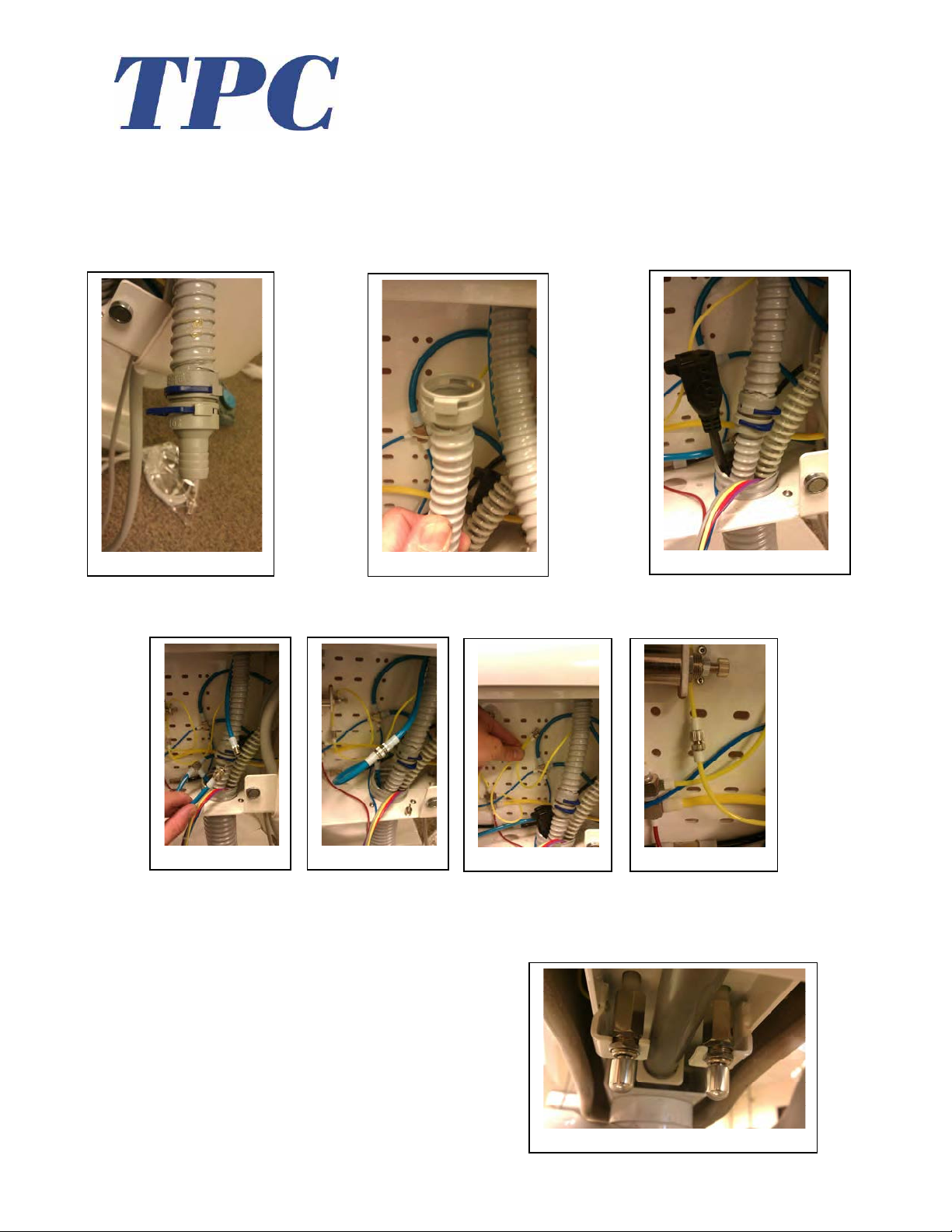
Cuspidor Plumbing Connections
16. Connect the drain line. Remove the blue locking tab to separate the quick connect from
the junction. Insert the removed end into the drain line tubing. Connect the two ends
together and replace the locking clip.
17. Remove the cap from the large water supply line, Connect the water supply line to the
cuspidor. Remove the cap from the signal air line, then connect it to the cuspidor.
18. The 2000C cuspidor possesses timing adjustments. In the event that you need to make
adjustments, the timing pressure release valves are located on the bottom of the cuspidor.
These adjustments will shut off the water flow so that you may fill a specified cup size, or
bowl rinse cycle time.
11
www.tpcdental.com
Page 35
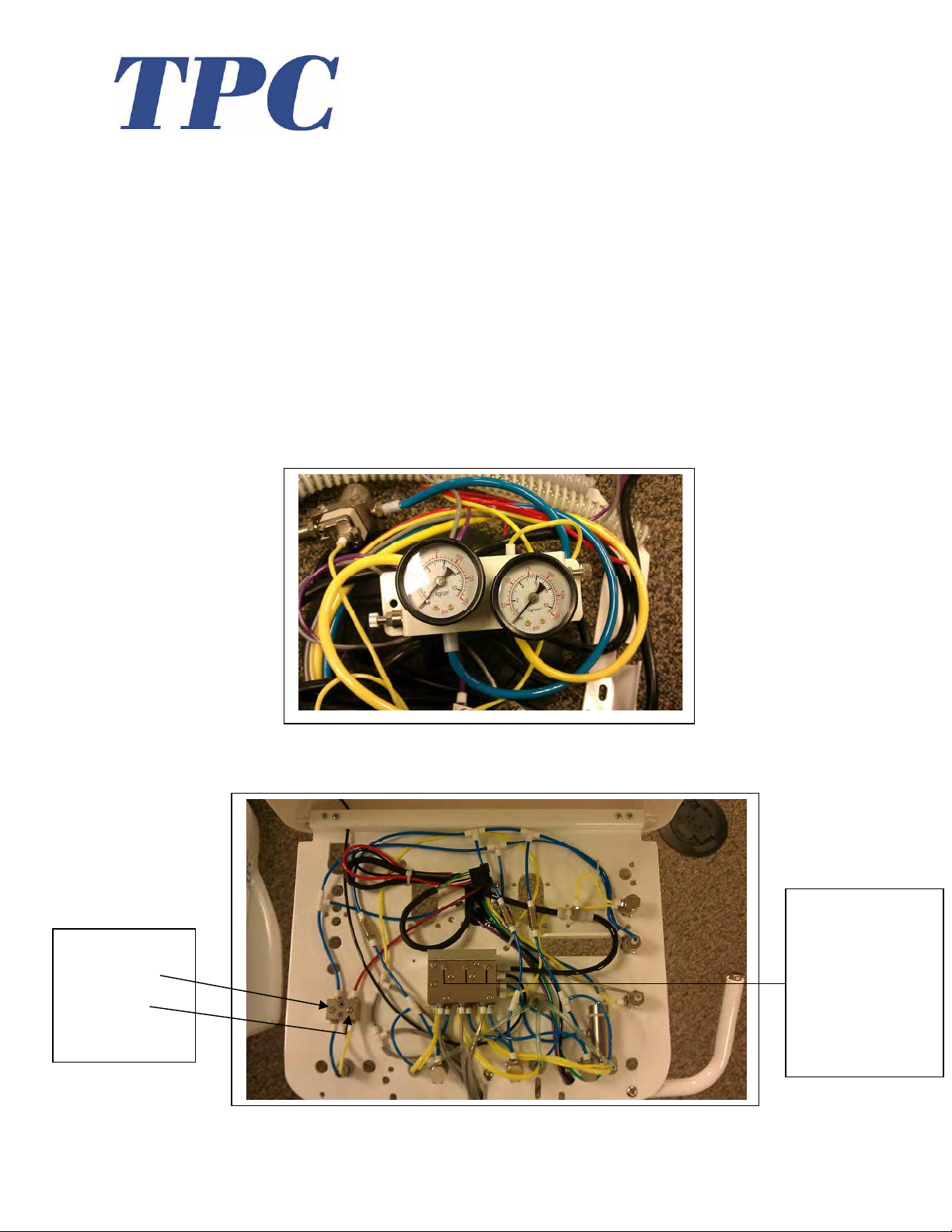
pressur e.
19. Before making any connections in the junction box, be sure to clear the supply lines. If
20. Once the line are verified and cleared, you may connect the master controls. The master
21. Once the connections are made you may open the angle stops or
22. Once air and water pressure are set, you may now make adjustments to the syringe blocks
Syringe Block:
Water Adjustment
Air Adjustment
Junction Box Connections
there is any debri in the air line it will collect on the micron filter. Verify the line is clear.
controls are similar looking. One is for the Air which is identified by the large yellow
tubing that exits the back end of the master control valve. The master control for the
water line is identified by the large blue line that exits the back of the master control
valve.
equivalent
valve. Once the valve is open you may check the mater control gauges and verify that the
pressures are set accordingly. Air pressure should read approximately 80 PSI. Water
pressure should read 40 PSI.
if necessary. Also check your handpiece pressure and adjust accordingly.
shut off
Handpiece
Pressure Adjustment
Use a flat head screw
drive to make adjustments.
Turning clockwise will
decrease the pressure.
Turning counter clockwise
will increase the air
12
www.tpcdental.com
Page 36
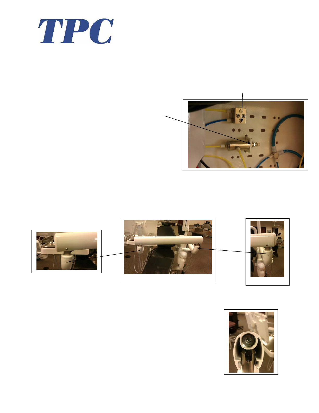
Post mount utility center adjustments (PMU)
1. There are two main adjustments that can be made in the PMU.
• Assistant's side syringe block adjustments
Turning the screw counter clockwise will increase the air / water pressure.
Turning the screw clockwise will decrease the air / water pressure.
• Water bottle pressure adjustments
Loosen the lock nut, then turn the
knob counter clockwise to decrease
the air pressure. Turn the knob
clockwise to increase pressure.
DONT allow more then 40PSI of air
pressure to supply the bottle.
Tension Adjustments
2. In a situation that you need to add tension to the delivery unit flex arms please see the
following locations. NOTE: tension adjustments are only a temporary fix for drifting
arms. If your arms are drifting first verify the PMU is level. Check the light post to verify
its plum. If light post is not level make the proper adjustments by re-leveling the unit.
Tension spring adjustment
3. If you need to make adjustments to the tension spring in the flex arm follow the
procedure below.
• Remove the flex arm cap cover.
• Use a 3/8" ratchet with 2" extension
• Turn clockwise to increase the tension
• Turn counter clockwise to decrease tension.
• Only make adjustments in half turn increments.
13
www.tpcdental.com
Page 37
delivery head leveling and tilt adjustments
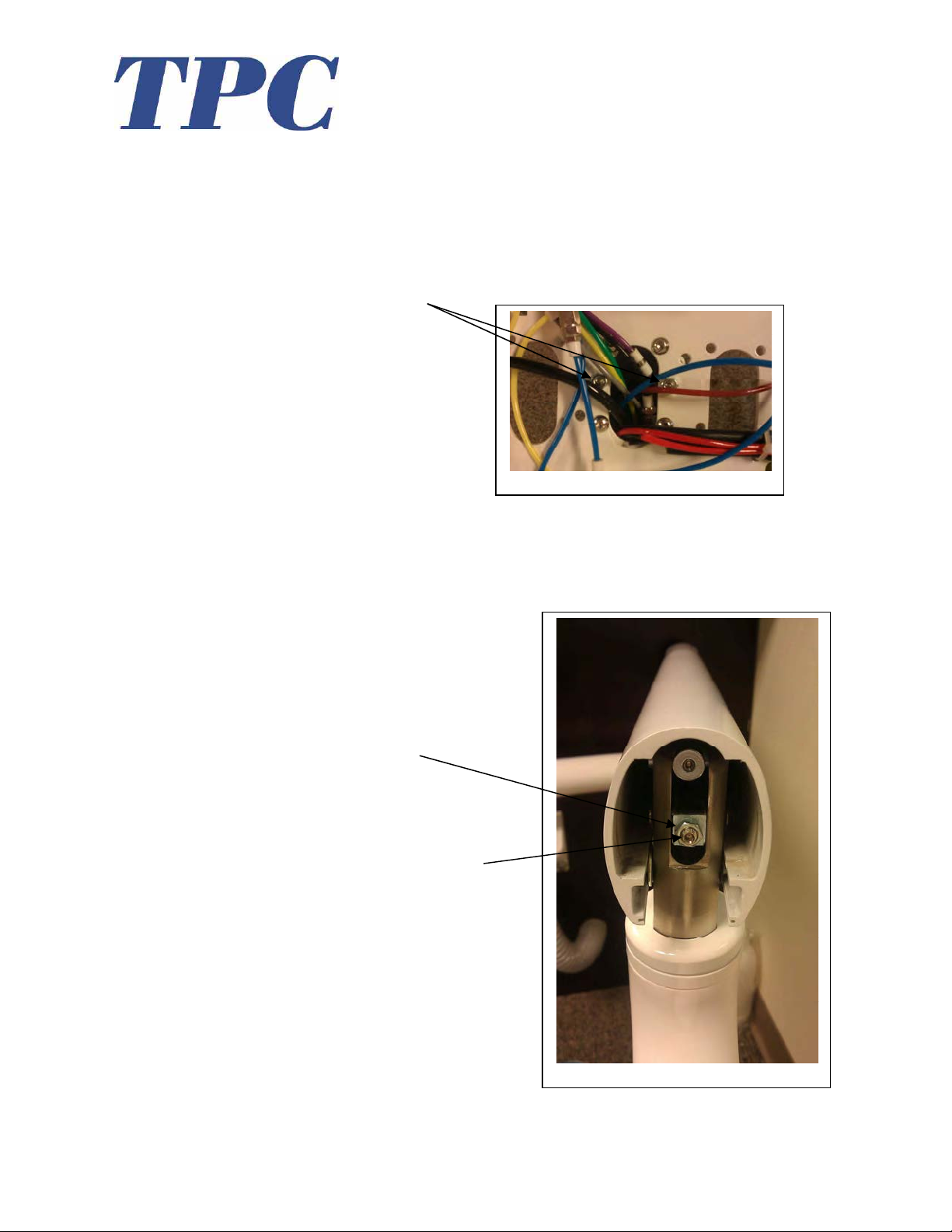
4. If you need to level the unit head or adjust the tilt use the following adjustments.
• Loosen the 4 Allen screws that attach the unit head to the short control arm. See
image. Once the screws are loose, use the two adjustment screws in the center on
each side to level the head.
• To adjust the unit head tilt, remove the flex arm end cap closest to the delivery
unit head. Loosen the stop nut, and using an Allen wrench turn the adjustment
screw clockwise to increase the tilt of the delivery unit head. Turn the adjustment
screw counter clockwise decrease the tilt.
*Stop Nut
*Adjustment Screw
14
www.tpcdental.com
Page 38

Tubing and connections
Junction Box
1. Yellow 6 X 4 Air Supply line
2. Blue 6 X 4 Water Supply line
3. Grey Master Switch Supply
4. Yellow Master switch return
5. Purple Air brake supply
6. Red Spare
Post mount utility center (from umbilical to delivery unit arm)
1. Yellow 6 X 4 Supply line T to unit head.
2. Black 6 X 4 from output from foot control
3. Small Yellow / Small Yellow Master Switch return
4. Small Gray / Small Gray supply line to master switch
5. Small Purple / Small purple Supply to break
6. Small Blue / Small blue water supply line
7. Small burgundy Spare line
8. Small Green / Gray (wet dry toggle from F.C)
9. Small Black Spare (to flex arm)
10. Small Red Spare (to flex arm)
15
www.tpcdental.com
 Loading...