

Page 1
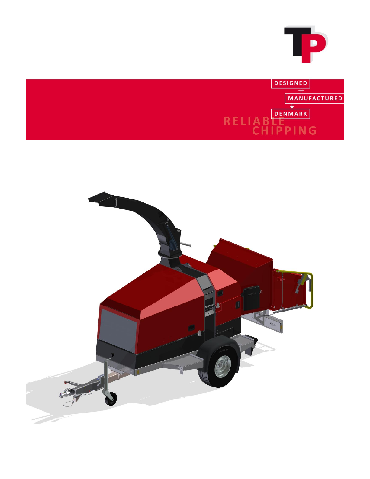
User Manual and Spare Parts Catalogue
TP 235 MOBILE
TP 275 MOBILE
1 User Manual: TP 235 MOBILE / TP 275 MOBILE from date 01.12.2016
Page 2
Ó
Copyright 2015
1 Introduction
Congratulations on your new TP wood chipper.
Linddana produces TP wood chippers of the finest quality by using the most modern production
technologies, such as laser cutting, CNC technology and robot technology in bright and open
production facilities.
For safety reasons and in order to get the maximum benefit from your wood chipper, it is
important you read the user manual before use.
Originally written in Danish, the user manual provides an explanation of safety, use and
maintenance, to ensure working with the wood chipper will be safe and profitable.
Linddana A/S
Hans Anker Holm, CEO
Your local dealer is always available with spare parts, advice and guidance.
Dealer stamp
Applies to Denmark (for all other countries contact the local TP dealer):
Linddana provides a knife sharpening service, so your knives can be sharpened and sent back on
the same day as they are received (for more details tel.: +45 76904045).
To keep your wood chipper in top condition and prolong its lifetime, Linddana offers a service
contract, under which the wood chipper will be checked once a year by our technician, ideally in
collaboration with the user. In addition to a technical check, the user will be given advice on the
use and maintenance of the wood chipper.
2 User Manual: TP 235 MOBILE / TP 275 MOBILE from date 01.12.2016
Page 3

Ó
Copyright 2015
2 EU DECLARATION OF CONFORMITY
Manufacturer:
LINDDANA A/S, Ølholm Bygade 70, Ølholm, DK-7160 Tørring, Denmark
hereby declares that
Wood chipper:
______________________________________________
and accompanying extra equipment is in conformity with the requirements of the Machinery
Directive (Directive 06/42/EC) and with the national legislation which translates this directive;
furthermore, is in conformity with the following EC Directives:
2000/14/EC
Furthermore it is stated that
EN 13525 (harmonised standard), has been applied.
Title: CEO
Name: Hans Anker Holm
Ølholm, 1. December 2016
User Manual: TP 235 MOBILE / TP 275 MOBILE from date 01.12.2016 3
Page 4

Ó
Copyright 2015
3 Contents
1 Introduction .................................................................................................... 2
2 EU DECLARATION OF CONFORMITY ................................................................. 3
3 Contents .......................................................................................................... 4
4 Use and safety ................................................................................................. 6
4.1 Mandatory Instructions and Warnings ............................................................................. 6
4.2 Pictograms used ............................................................................................................ 16
5 Noise level ..................................................................................................... 18
5.1 Environmental instructions ............................................................................................ 18
6 Handling ........................................................................................................ 19
7 Before start-up .............................................................................................. 20
7.1 Check the wood chipper before start-up........................................................................ 20
7.2 Opening and closing of disc housing .............................................................................. 21
7.3 Opening and closing by TP EASY SERVICE ....................................................................... 24
7.4 Opening and closing the revolving roller. ....................................................................... 26
8 Operating the wood chipper .......................................................................... 28
8.1 Safety bar ...................................................................................................................... 28
8.2 TP VARIO SPOUT ............................................................................................................ 29
8.3 In-feed speed ................................................................................................................. 30
8.4 Start-up and commissioning the wood chipper .............................................................. 30
8.5 Connecting and disconnecting instructions .................................................................... 31
8.6 Foldable funnel .............................................................................................................. 33
8.7 TP TURNTABLE ............................................................................................................... 34
9 TP NAVIGATOR .............................................................................................. 36
9.1 Key ................................................................................................................................ 36
9.2 Operating TP NAVIGATOR .............................................................................................. 36
9.3 Top menu ...................................................................................................................... 37
9.4 Page menu..................................................................................................................... 37
10 Maintenance .............................................................................................. 43
10.1 Maintenance schedule for wood chipper ....................................................................... 44
10.2 Hydraulic oil table .......................................................................................................... 44
10.3 Maintenance schedule for engine .................................................................................. 45
10.4 Engine oil level ............................................................................................................... 46
10.5 Hydraulics ...................................................................................................................... 46
10.6 Knives ............................................................................................................................ 48
10.7 Counterknife .................................................................................................................. 50
10.8 Square and triangle scrapers and scrapers ..................................................................... 51
10.9 Cleaning the filter in front of the radiator ...................................................................... 52
10.10 Related to battery ...................................................................................................... 53
11 Hydraulics .................................................................................................. 54
11.1 Replacing hydraulic hoses .............................................................................................. 54
11.2 Hydraulics diagram, TP 235 MOBILE .............................................................................. 55
11.3 Hydraulics diagram, TP 275 MOBILE .............................................................................. 56
12 Electrical diagram TP 235 and TP 275 ......................................................... 57
12.1 Diagram engine ............................................................................................................. 57
12.2 Power line on engine ..................................................................................................... 60
4 User Manual: TP 235 MOBILE / TP 275 MOBILE from date 01.12.2016
Page 5

Ó
Copyright 2015
12.3 Diagram TP NAVIGATOR ................................................................................................ 63
12.4 Electrical diagram trailer ................................................................................................ 65
13 Troubleshooting ......................................................................................... 67
14 Warranty terms wood chipper ................................................................... 68
15 Technical data wood chipper ...................................................................... 69
16 Extra equipment ......................................................................................... 72
16.1 TP CHIP KIT .................................................................................................................... 72
16.2 TP TOOLKIT .................................................................................................................... 74
16.3 TP SPARE WHEEL ........................................................................................................... 75
16.4 TP SPARE WHEEL (TP TURNTABLE) ................................................................................. 77
17 Spare Parts Catalogue ................................................................................ 80
User Manual: TP 235 MOBILE / TP 275 MOBILE from date 01.12.2016 5
Page 6
Ó
Copyright 2015
4 Use and safety
This TP wood chipper is specially designed as a stationary wood chipper, which chips wood in the
form of branches, bushes and waste wood from windbreaks, parks, roadside trees, etc.
Any modification to the design of the machine is strictly prohibited. In the event that modifications
are made, Linddana A/S disclaims all liability.
4.1 Mandatory Instructions and Warnings
4.1.1 Before use
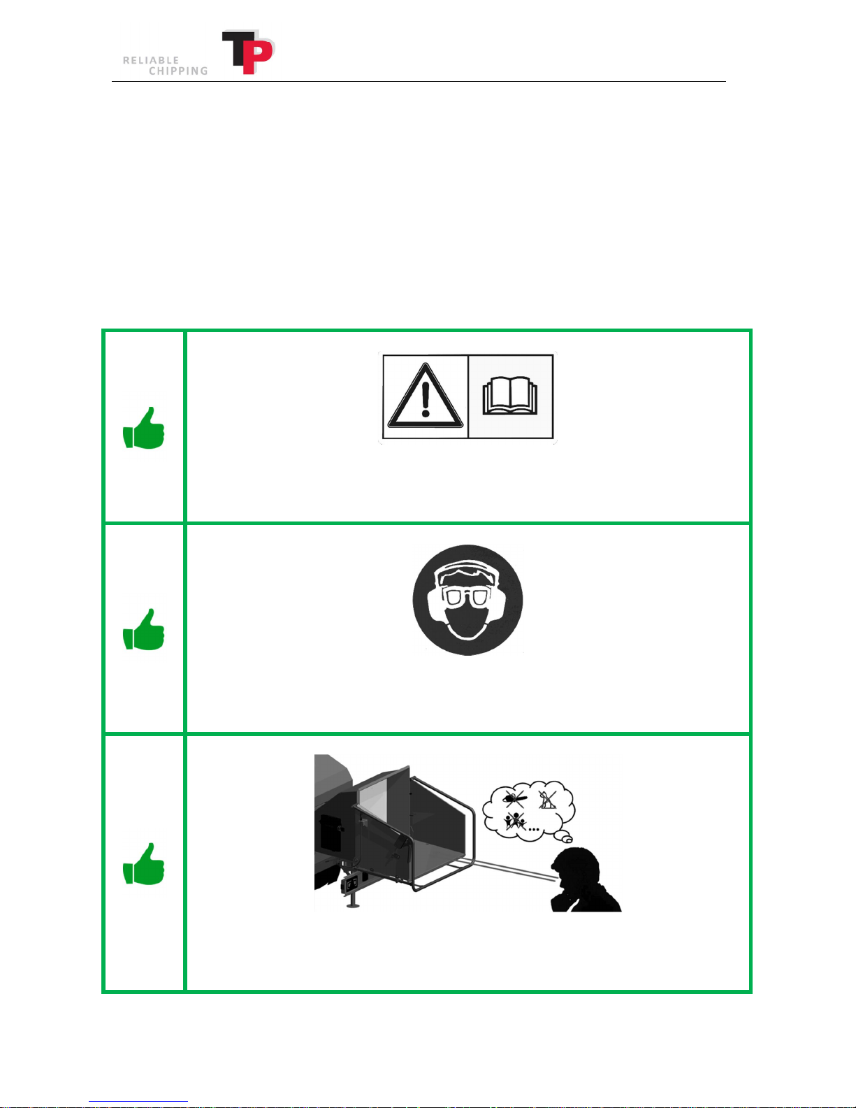
ALWAYSread the user manual before using the wood chipper.
Remember to store the user manual in the manual box.
ALWAYS wear ear protectors, safety goggles, close fitting safety clothing and safety
shoes.
ALWAYS ensure that the funnel is free of people, animals and other foreign bodies
before starting the wood chipper.
6 User Manual: TP 235 MOBILE / TP 275 MOBILE from date 01.12.2016
Page 7
Ó
Copyright 2015
ALWAYS ensure that all of the guards are securely closed/fitted before starting the
wood chipper
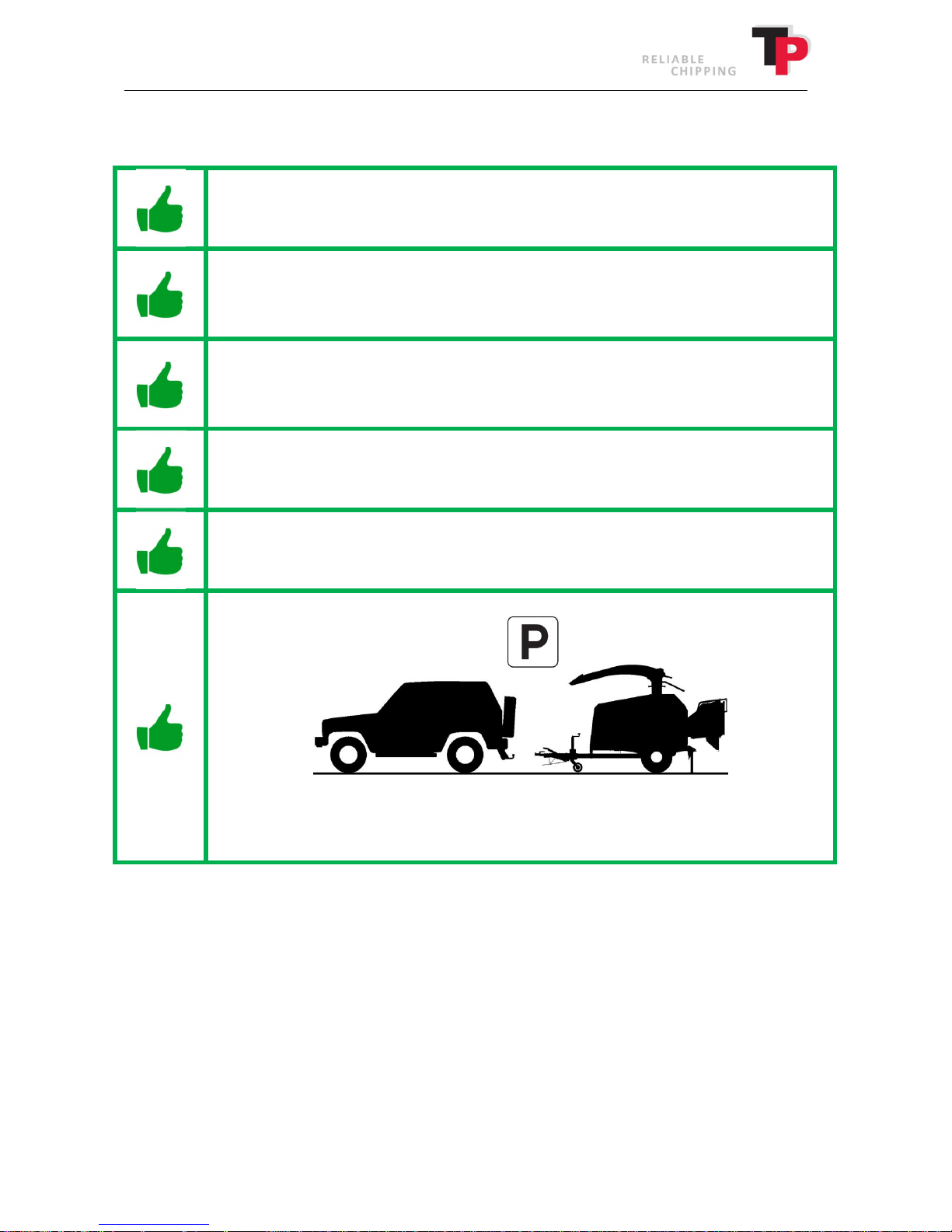
ALWAYS ensure that the wood chipper is safely parked before starting the wood
chipper.
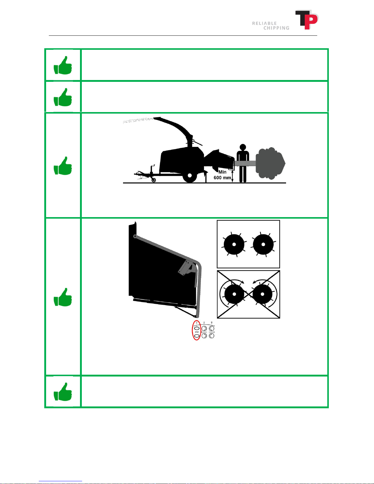
ALWAYS ensure there is more than 600 mm of clearance between the ground and the
wood chipper's lowest funnel edge and that it stands on a level surface.
ALWAYS ensure that all of the safety devices function correctly before starting the
wood chipper. This applies in particular to the safety bar's STOP function.
ALWAYS observe the ground conditions around the wood chipper. Falling down in the
vicinity of the wood chipper is hazardous.
User Manual: TP 235 MOBILE / TP 275 MOBILE from date 01.12.2016 7
Page 8
Ó
Copyright 2015
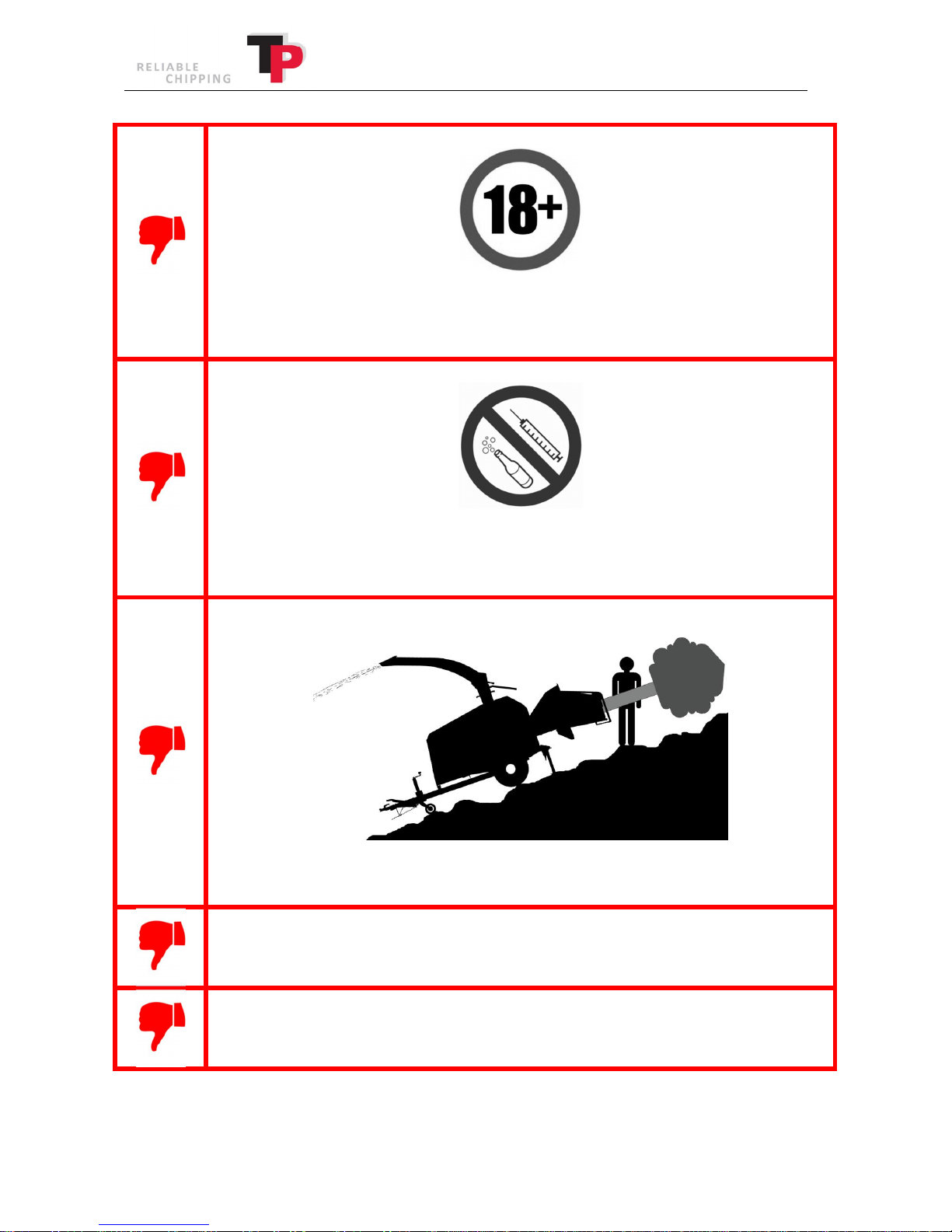
NEVER allow anyone under 18 years of age to operate the wood chipper (however,
anyone who is 16 years old and over may do so under the supervision of an adult).
NEVER operate the wood chipper if under the influence of alcohol or narcotic
substances.
NEVER operate the wood chipper on uneven or inclined surfaces.
NEVER start the wood chipper without the ejector spout fitted.
NEVER use the wood chipper in enclosed or poorly ventilated spaces, because of the
danger of carbon monoxide poisoning.
8 User Manual: TP 235 MOBILE / TP 275 MOBILE from date 01.12.2016
Page 9
Ó
Copyright 2015
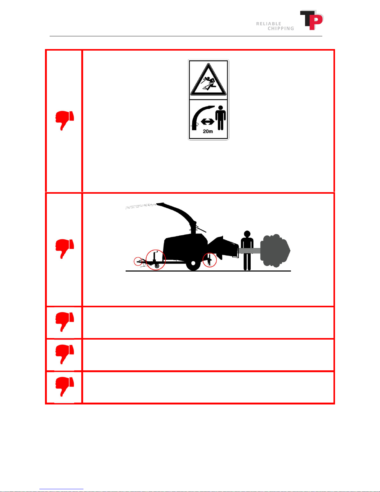
NEVER point the ejector spout in the same direction as people or at an area that
people move around in.
A safe distance of 20 m must be maintained in the direction of where the woodchip is
ejected.
NEVER operate the wood chipper without support from the jack and support leg or
from the vehicle's trailer hitch.
NEVER use the wood chipper with material that is not wood.
NEVER use the wood chipper to push trees, stumps, etc.
NEVER transport equipment in the funnel, such as forest chains, axes, chainsaws, etc.
User Manual: TP 235 MOBILE / TP 275 MOBILE from date 01.12.2016 9
Page 10
4.1.2 During operation
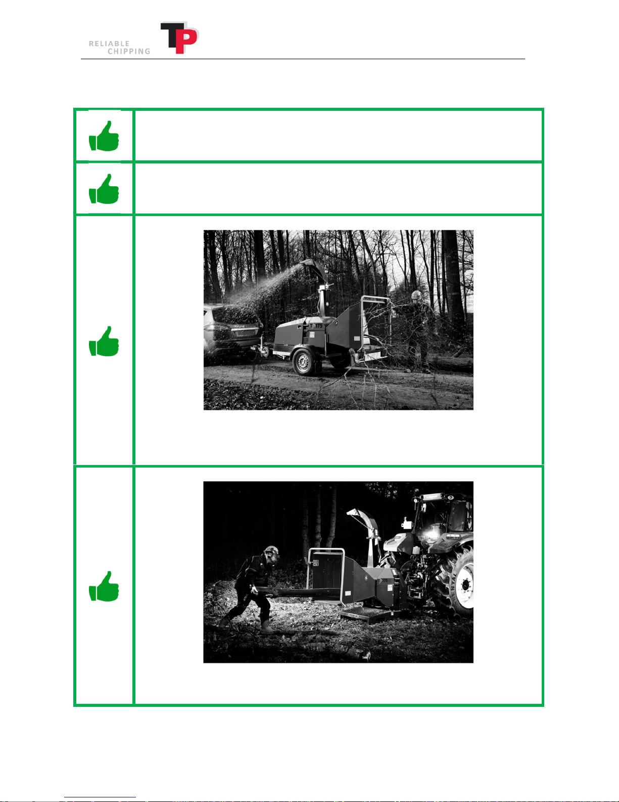
ALWAYS push the safety bar into the STOP position if a dangerous situation arises
(see chapter 8).
ALWAYS keep body parts away from the funnel and wood chipper's other moving
parts.
Ó
Copyright 2015
ALWAYS stand at the side of the funnel when the wood chipper is chipping trees that
have branches.
ALWAYS push logs in from the rear of the log.
10 User Manual: TP 235 MOBILE / TP 275 MOBILE from date 01.12.2016
Page 11
Ó
Copyright 2015
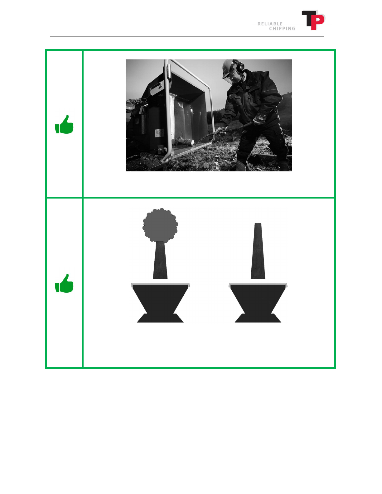
ALWAYS use a rod to push short pieces of tree into the rollers.
ALWAYS feed the wood chipper with the thick end of the log first.
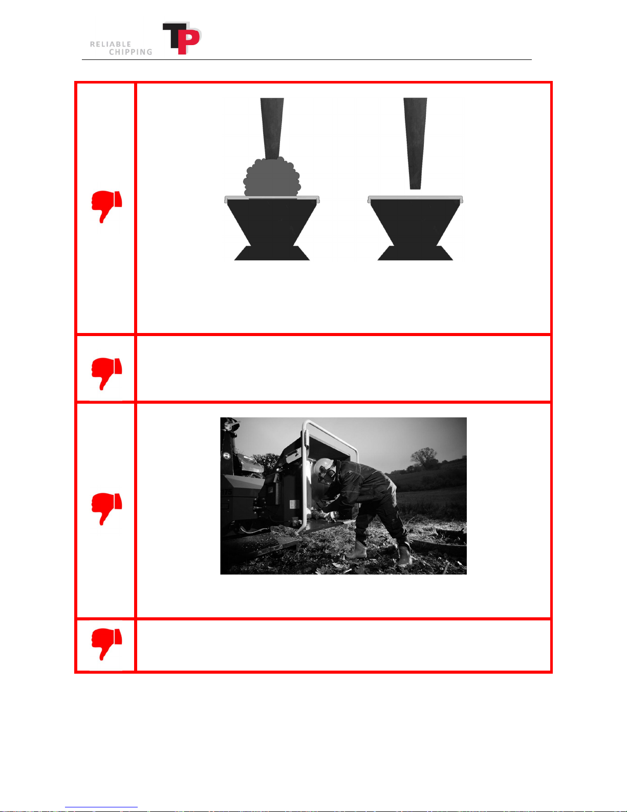
ALWAYS feed the wood chipper so that the tree crown points away from the funnel.
User Manual: TP 235 MOBILE / TP 275 MOBILE from date 01.12.2016 11
Page 12
Ó
Copyright 2015
NEVER feed the tree crown into the wood chipper first.
NEVER feed the wood chipper with the thin end of the log first.
NEVER attempt to remove any trapped material from between the feed rollers before
the wood chipper has stopped, the key has been removed and the revolving roller has
been opened as described in chapter 7.4.
NEVER reach into the funnel to push wood into the rollers.
NEVER open or remove the guard while the wood chipper is operating.
12 User Manual: TP 235 MOBILE / TP 275 MOBILE from date 01.12.2016
Page 13
Ó
Copyright 2015
4.1.3 Transport and parking
ALWAYS comply with local public authority regulations when transporting the wood
chipper on public roads.
ALWAYS keep the ejector spout completely down in the bottom during transport.
Remember to ensure that the transport lock is engaged.
ALWAYS keep the ejector spout within the width of the machine during transport.
Remember to ensure that the ejector spout is securely fastened.
ALWAYS place the foldable funnel in the transport position during transport (the
funnel must be folded up and locked with pin).
ALWAYS ensure that all of the wood chipper lights work correctly before operating.
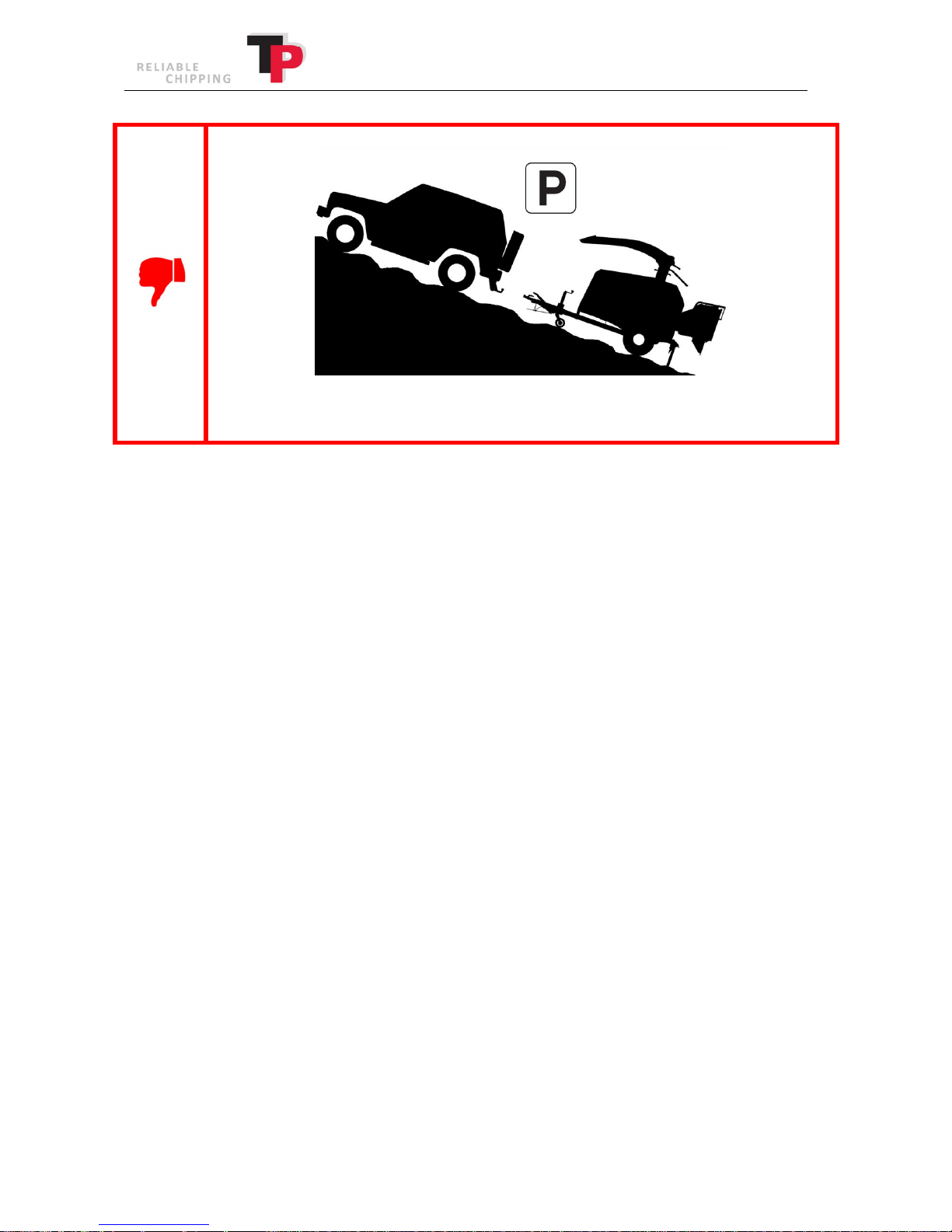
ALWAYS park the wood chipper on a level surface.
User Manual: TP 235 MOBILE / TP 275 MOBILE from date 01.12.2016 13
Page 14
Ó
Copyright 2015
NEVER park the wood chipper on inclined or uneven surfaces.
14 User Manual: TP 235 MOBILE / TP 275 MOBILE from date 01.12.2016
Page 15
Ó
Copyright 2015
4.1.4 Service and repairs
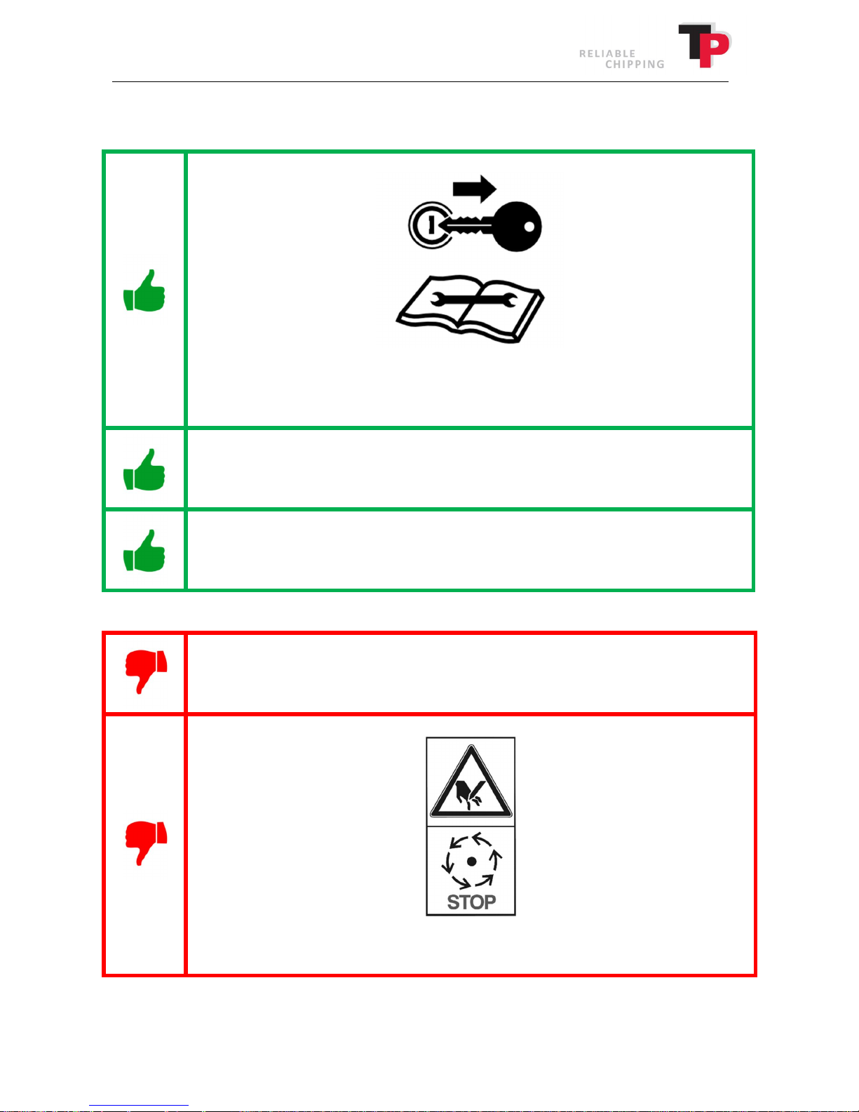
ALWAYS remove the key from the ignition and ensure the disc has stopped moving
before carrying out service or repairs.
ALWAYS after service or repair, ensure that all of wood chipper bolts are fitted and
tightened securely and that all of the safety devices are fitted and function properly.
ALWAYS ensure that the knives, counterknives and rollers are kept sharp. This results
in smoother in-feed, higher woodchip quality and less fuel consumption.
NEVER carry out service or repairs on the wood chipper while the key is in the ignition
lock.
NEVER remove or open the guards before the disc has stopped moving.
User Manual: TP 235 MOBILE / TP 275 MOBILE from date 01.12.2016 15
Page 16
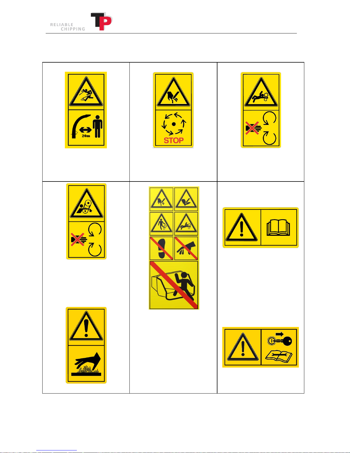
4.2 Pictograms used
Ó
Copyright 2015
Warning: Ejected Objects!
Warning: Safe distance of 20 m!
Warning: Crushing hazard!
Warning: Rotating belts!
Warning: Hot surface!
Warning: Rotating knives!
Warning: Wait for disc to stop!
Warning: Danger of severed
limbs!
Warning: Crushing hazard!
Warning: Do not step on the
funnel!
Warning: Do not touch the
funnel!
Warning: Do not climb into the
funnel!
Warning: Crushing hazard!
Warning: Rotating rollers!
Warning: Read the instruction
manual before use!
Warning: Remove the ignition
key and read the user manual
before service or repairs
16 User Manual: TP 235 MOBILE / TP 275 MOBILE from date 01.12.2016
Page 17
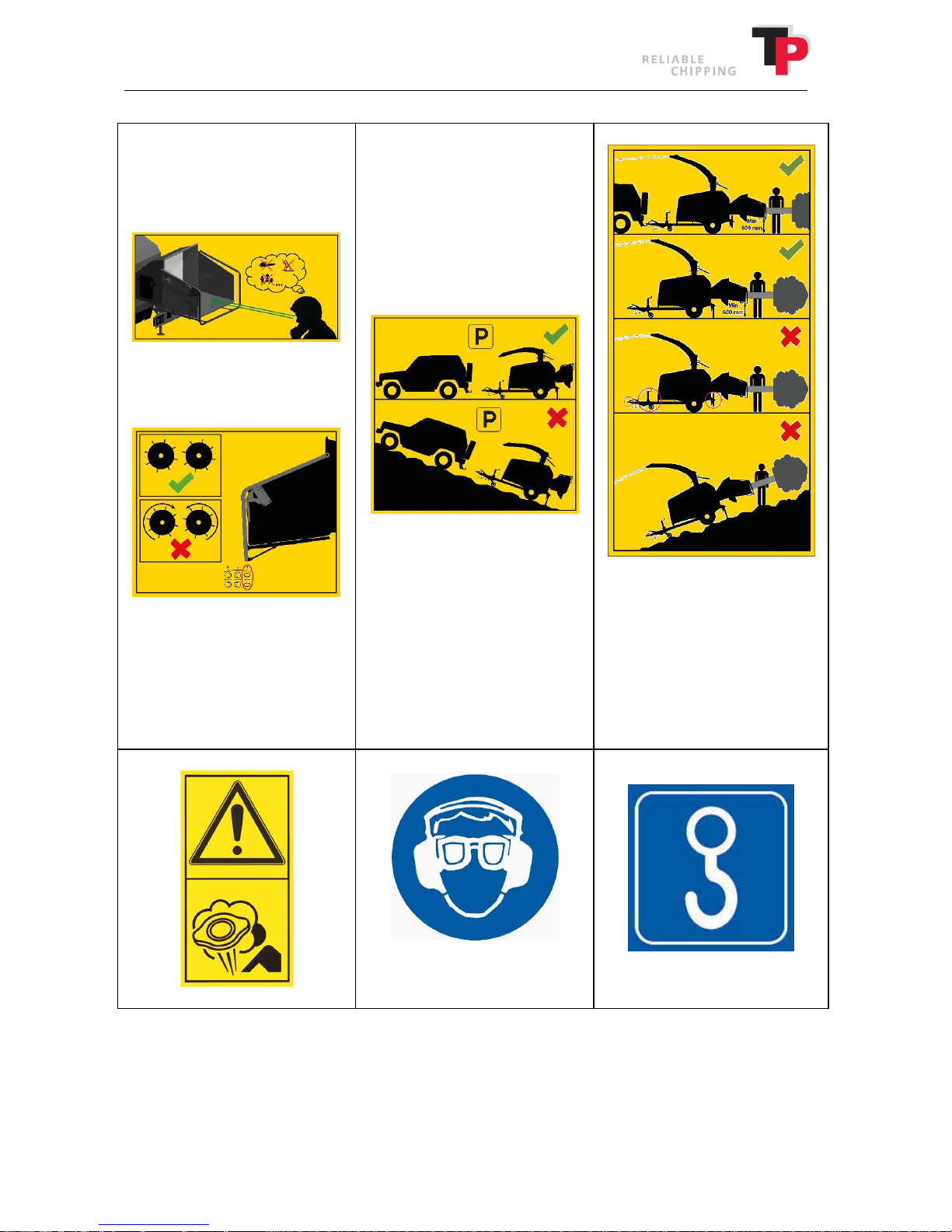
inclined surfaces!
Ó
Copyright 2015
Warning: Ensure that the funnel
is free of people, animals and
other foreign bodies!
Warning: Do not park on
uneven or inclined surfaces!
Warning: Do not operate the
Warning: Ensure the safety
bar works!
wood chipper without support
from the jack and support leg
or from the vehicle's trailer
hitch!
Warning: Do not operate the
wood chipper on uneven or
Ear and eye protection
Warning: Danger of scalding!
mandatory!
Lifting point for crane!
For safety information and pictograms on the engine, see engine manual.
User Manual: TP 235 MOBILE / TP 275 MOBILE from date 01.12.2016 17
Page 18

Ó
Copyright 2015
5 Noise level
The sound output level and the sound pressure level for every wood chipper has been measured
during use with the disc at nominal rpm, powered by the engine. For specific rpm values and
engine types (see technical data wood chipper in chapter 15).
The measurements have been conducted in accordance with testing provisions
Directive 2000/14/EC, 3 July 2000
EN ISO 3744, 1995
ISO 11201, 1995
ISO 4871, 19 March 1997
EN 13525, 17 February 2005
The guaranteed sound output level which must be stated by the manufacturer in accordance with
Directive 2000/14/EC is as follows:
TP 235 MOBILE: 128 dB (A) relative to 1 pW
TP 275 MOBILE: 129 dB (A) relative to 1 pW
The wood chipper’s sound pressure level at the operator’s position is measured in accordance
with ISO 11201 and measured as:
TP 235 MOBILE: 109 dB (A)
TP 275 MOBILE: 110 dB (A)
The values stated above are subject to the common uncertainty of the measuring method and the
estimated variation in a product series for the type of machine. Detailed information about the
measurements and results and estimation of uncertainty are found in a detailed report which can
be supplied on request.
As a result of the actual sound levels, the wearing of ear protectors is mandatory when using the
wood chipper.
5.1 Environmental instructions
When changing hydraulic oil or engine oil, oil and used oil filters and air filters must be disposed of
at an approved waste disposal station.
Oil spillage must be avoided as far as possible. Should oil spillage occur, the spilled oil must be
cleaned up and disposed of at an approved waste disposal station.
Worn out parts must be disposed of for recycling.
When the wood chipper is worn out it must be disposed of responsibly. Hydraulic oil and engine
oil must be drained and disposed of along with oil filters and air filters at an approved waste
disposal station.
The rest of the wood chipper must be disposed of at an approved recycling centre.
18 User Manual: TP 235 MOBILE / TP 275 MOBILE from date 01.12.2016
Page 19
Ó
Copyright 2015
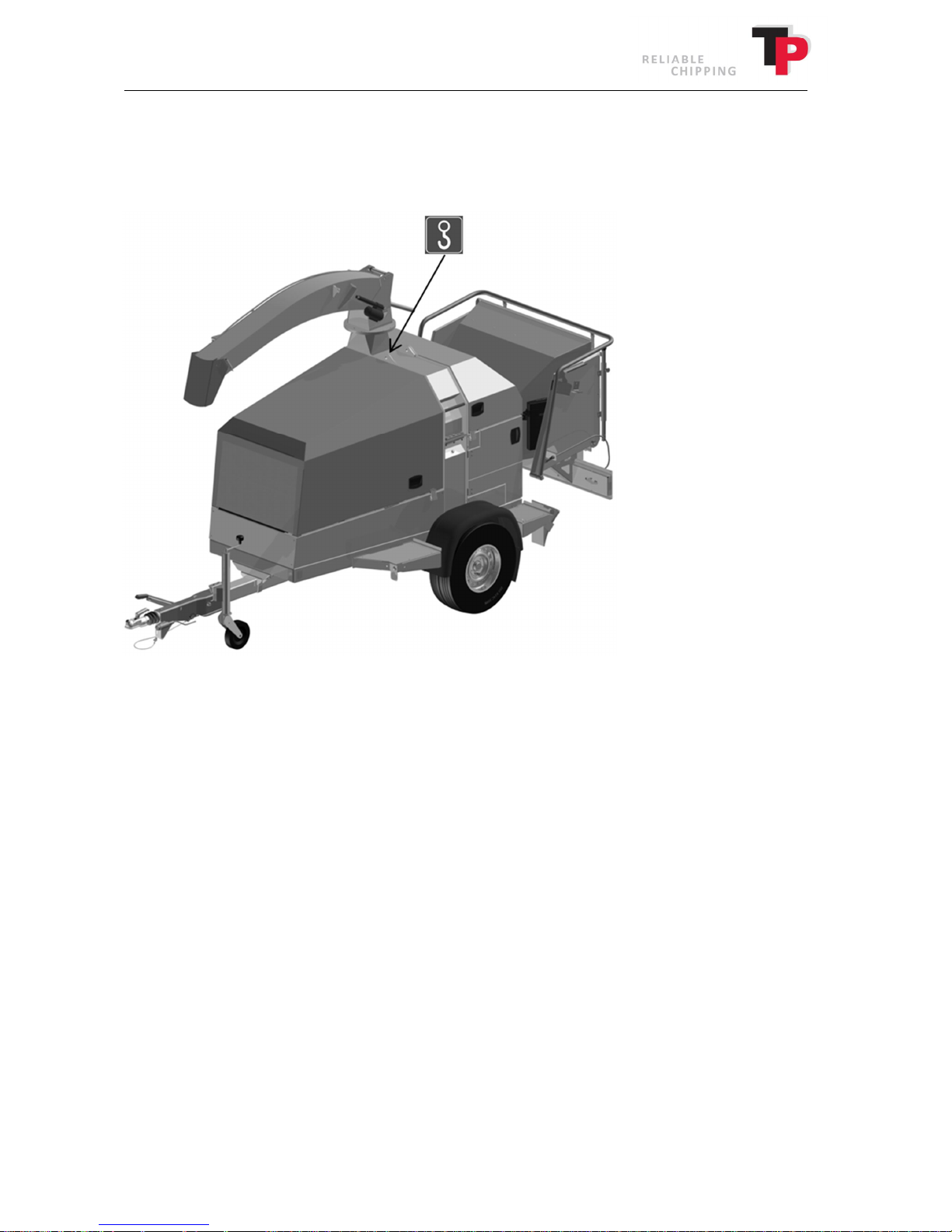
6 Handling
Lifting point
The wood chipper is equipped with a lifting point, which must be used whenever it is lifted by a
crane or other lifting gear (with hooks).
User Manual: TP 235 MOBILE / TP 275 MOBILE from date 01.12.2016 19
Page 20

Ó
Copyright 2015
7 Before start-up
7.1 Check the wood chipper before start-up.
Chipping unit
1. Open the disc housing, as described later in this chapter.
2. Ensure that the wood chipper is free of any foreign bodies by turning the disc a few times
by hand. Remove any foreign bodies.
3. Check that the knives run clear of the counterknives.
4. Ensure that the distance between the knives and counterknives is correct. The distance is
stated in chapter 10.
5. Close the disc housing, as described later in this chapter.
6. Ensure that all of the bolts, nuts and screws are tightened securely.
7. NB: Lubricate all of the lubrication points (see maintenance schedule, chapter 10).
Engine
1. Check the engine's oil level.
2. Check the coolant's level.
3. Check the fuel level.
20 User Manual: TP 235 MOBILE / TP 275 MOBILE from date 01.12.2016
Page 21
Ó
Copyright 2015
7.2 Opening and closing of disc housing
The wood chipper's key must be removed from the ignition when the disc housing is opened and
may only be re-inserted after the disc housing has been closed again!
Opening the disc housing
1. Check that the wood chipper's key is removed from the ignition and the disc has stopped
moving.
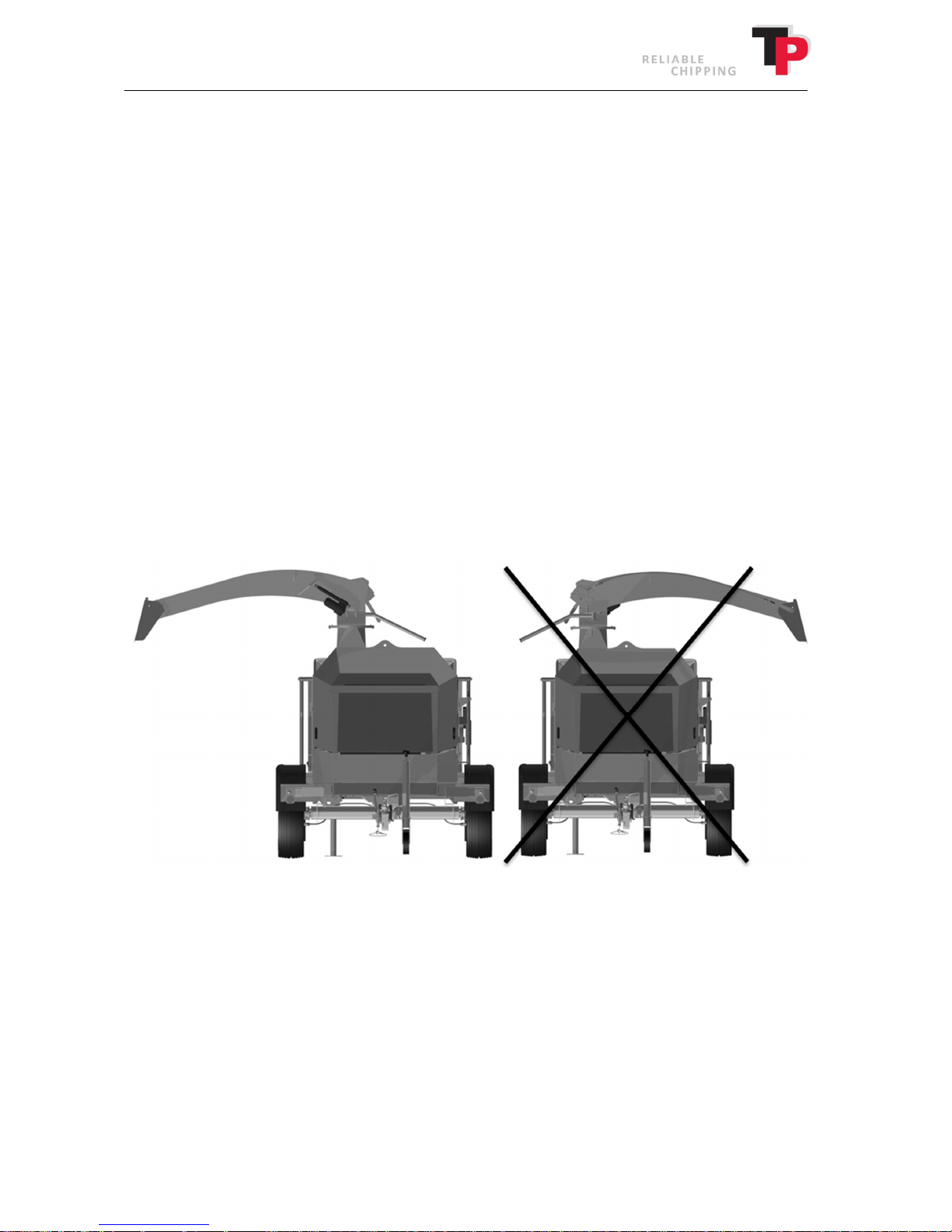
2. Lower the ejector spout all the way to the bottom. (If the model is equipped with TP VARIO
SPOUT). (See Operating the wood chipper in chapter 8).
3. Turn the ejector spout so that it faces the opposite direction of the disc housing (see
illustration below).
4. Open the bonnet. The bonnet is locked with an external catch on each side.
User Manual: TP 235 MOBILE / TP 275 MOBILE from date 01.12.2016 21
Page 22
Ó
Copyright 2015
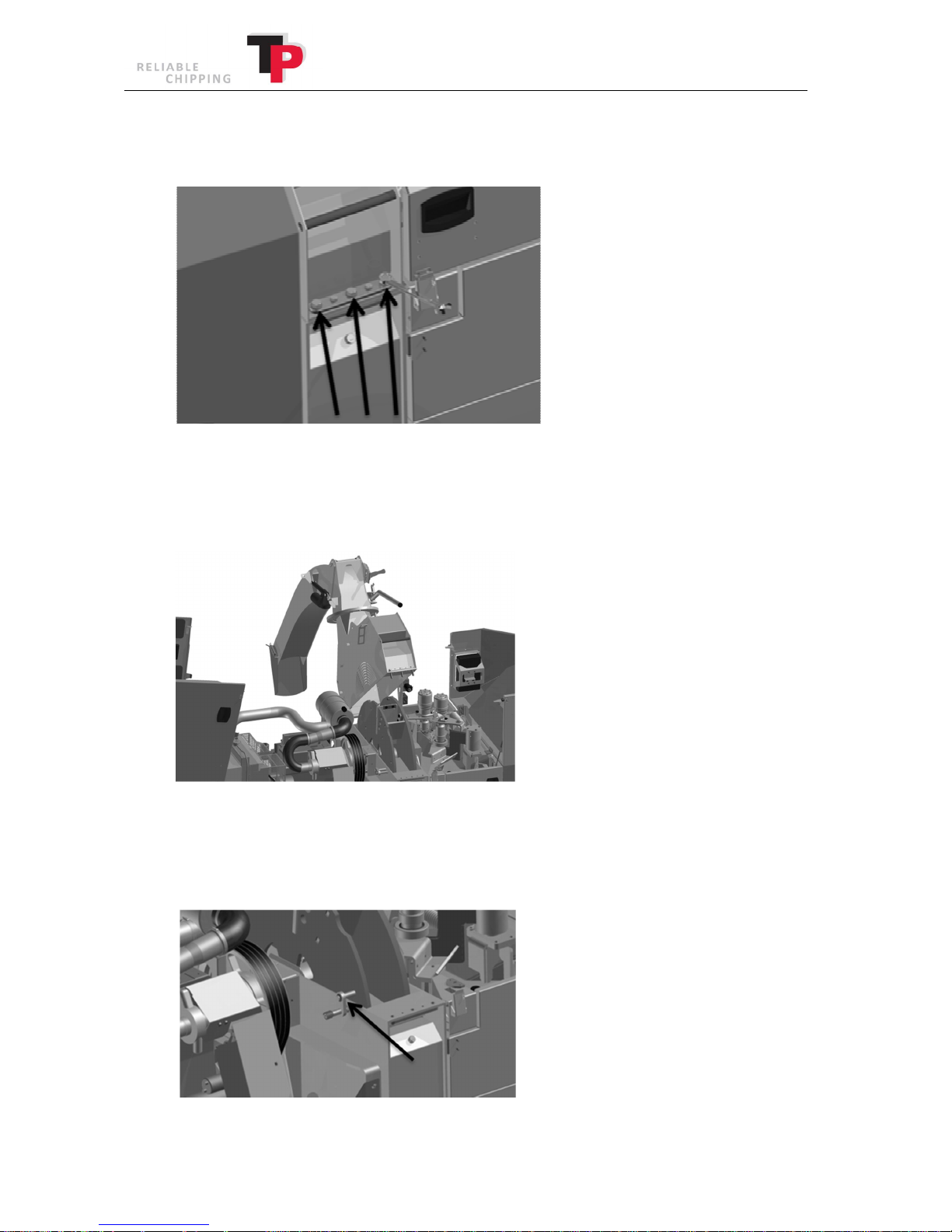
5. Loosen the three bolts that secure the disc housing top and bottom parts together (see the
illustration below).
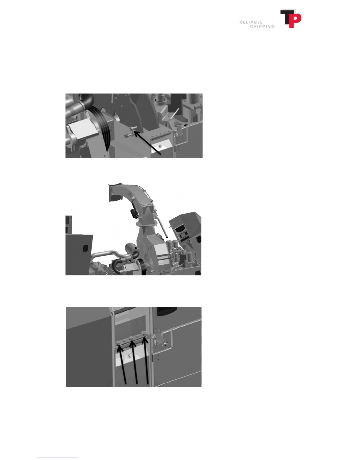
6. For easier access to the disc, open the cover over the in-feed. The cover is locked with an
external catch on each side.
7. Open the top part of disc housing until it meets the stop (see illustration below).
8. Turn the disc until the yellow disc lock can go into one of the holes on the disc. The disc is
now locked. Keep fingers away from the knives when the disc is being turned.
As far as possible, the disc must always be locked when the disc housing is open (see
illustration below).
22 User Manual: TP 235 MOBILE / TP 275 MOBILE from date 01.12.2016
Page 23
Ó
Copyright 2015
Closing the disc housing
1. Free the yellow disc lock from the disc and turn the disc a few times to make sure that
there are no objects in the disc housing. Exercise caution and keep fingers away from the
knives when the disc turns (see illustration below).
2. Lock the top part of the disc housing (see illustration below).
3. Tighten the three bolts to secure together the top and bottom parts of the disc housing
(see the illustration below).
4. Close the bonnet and the cover above the in-feed section and lock them securely using the
external catches. Turn the ejector spout into place and lock it. (See Operating the wood
chipper in chapter 8).
User Manual: TP 235 MOBILE / TP 275 MOBILE from date 01.12.2016 23
Page 24
Ó
Copyright 2015
7.3 Opening and closing by TP EASY SERVICE
The wood chipper is equipped with TP EASY SERVICE, which makes it easier to access to the
control/replacement of the counterknives and the rear of the in-feed.
Opening TP EASY SERVICE
To open TP EASY SERVICE, the left side cover has to be opened. The cover is locked with an
external catch on each side. Opening the cover over the in-feed will make accessing the disc
easier. The cover is locked with an external catch on each side.
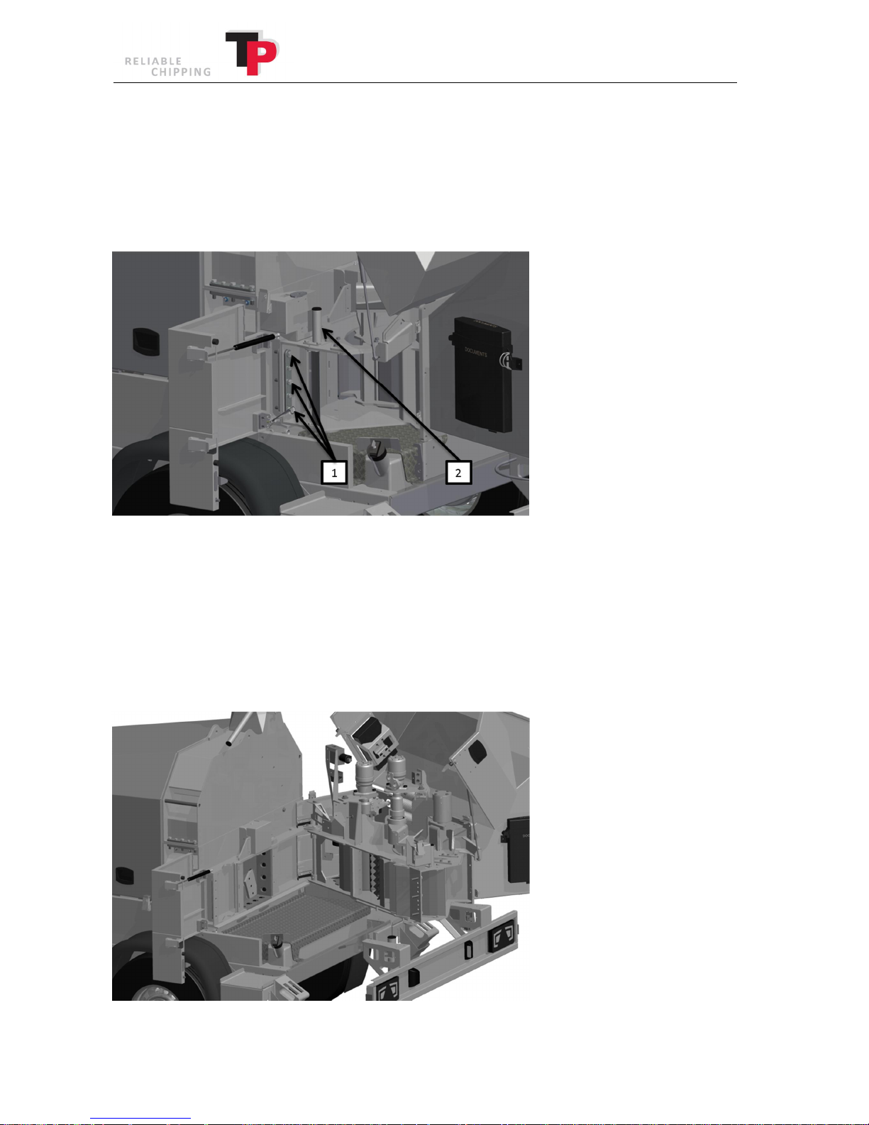
1. Loosen the three bolts (1) that secure the in-feed and disc housing.
2. Hold the handle (2) and pull the in-feed back until it meets the mechanical stop. The in-
feed is now fully open and automatically locked in this position (see illustration below).
24 User Manual: TP 235 MOBILE / TP 275 MOBILE from date 01.12.2016
Page 25
Ó
Copyright 2015
Closing TP EASY SERVICE
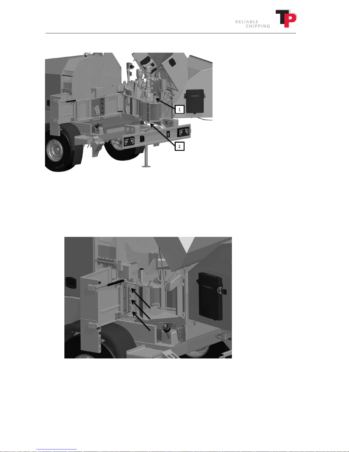
1. Hold the handle (1) and release the lock by pulling the locking handle (2).
2. Push the in-feed back into position against the disc housing.
3. Tighten the three bolts to secure together the in-feed and disc housing (see the illustration
below).
5. Close the left side screen and the cover above the in-feed and lock them securely using the
external catches.
User Manual: TP 235 MOBILE / TP 275 MOBILE from date 01.12.2016 25
Page 26
Ó
Copyright 2015
7.4 Opening and closing the revolving roller.
Opening the revolving roller
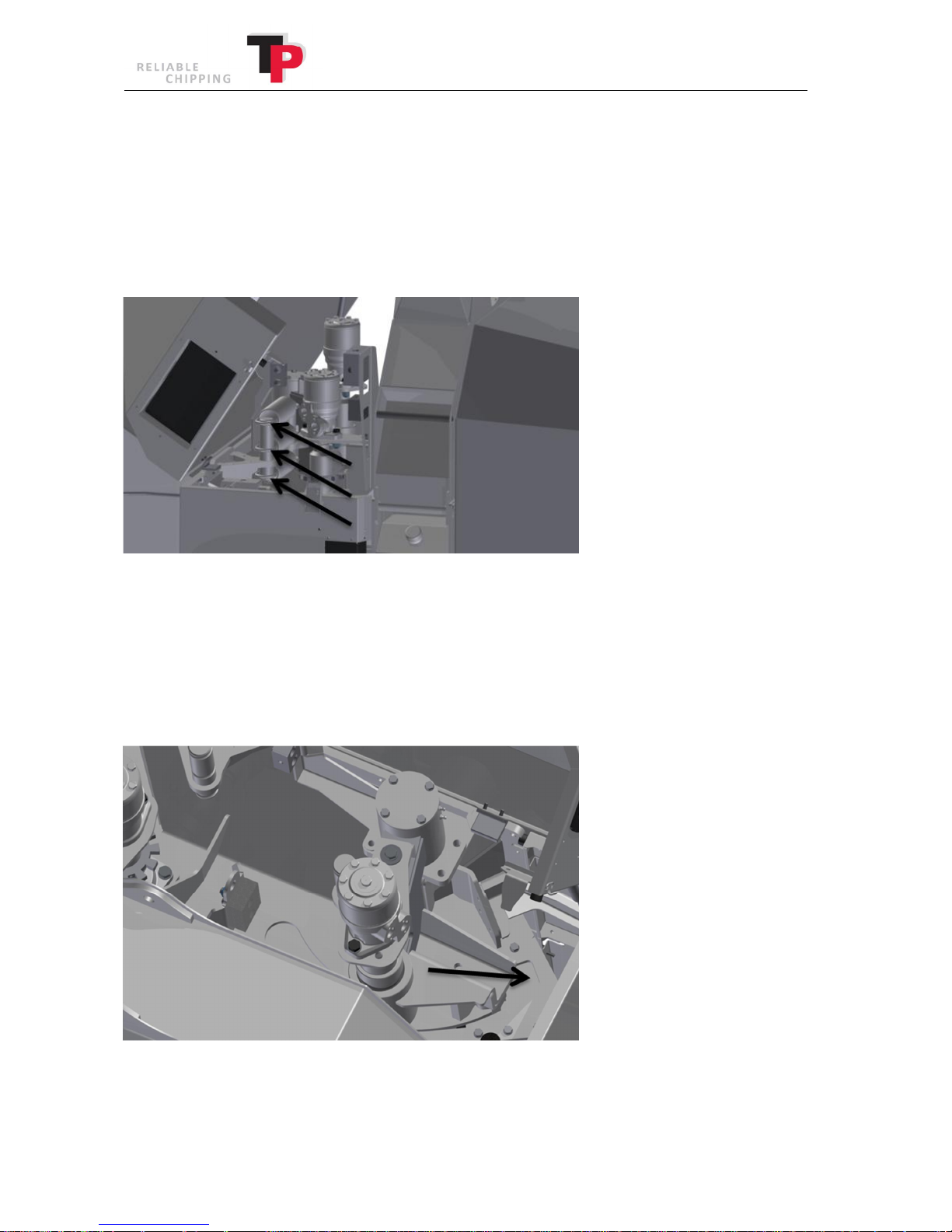
The revolving roller's retention force is created by springs. If the revolving roller needs to be
opened so that foreign bodies can be removed from the in-feed, the springs must be removed (see
illustration below).
1. Open the cover over the in-feed. The cover is locked with an external catch on each side.
2. Using multigrip pliers or similar, lift the springs from the spring holder (exercise caution
and keep fingers away from the springs when the spring holder is lifted).
3. The revolving roller is now free to open up against the secured opening stop (see
illustration below).
26 User Manual: TP 235 MOBILE / TP 275 MOBILE from date 01.12.2016
Page 27
Ó
Copyright 2015
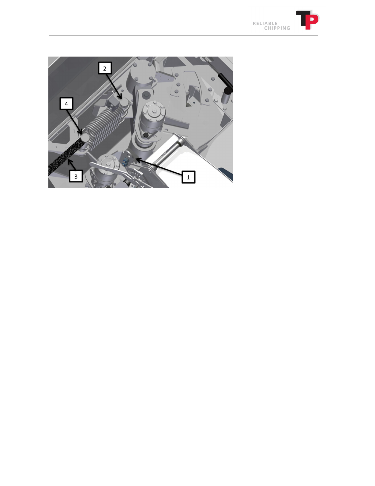
Closing the revolving roller
1. Close the revolving roller against the inside closing stop (1).
2. Fit the springs on the revolving roller's spring holder (2).
3. Using a flat fibre strap (3), pull the springs one after another, by placing the strap around
the spring's eyes and pulling on both ends of the fibre strap (the strap is a part of the TP
TOOLBOX). Once the spring has been pulled in across the spring holder on the in-feed (4),
release one end of the fibre strap and then pull it out of the spring's eye by pulling the
other end of the fibre strap. The springs can then slide into place in the spring guides.
4. Close the cover above the in-feed and lock securely using the external catches.
User Manual: TP 235 MOBILE / TP 275 MOBILE from date 01.12.2016 27
Page 28
8 Operating the wood chipper
8.1 Safety bar
Ó
Copyright 2015
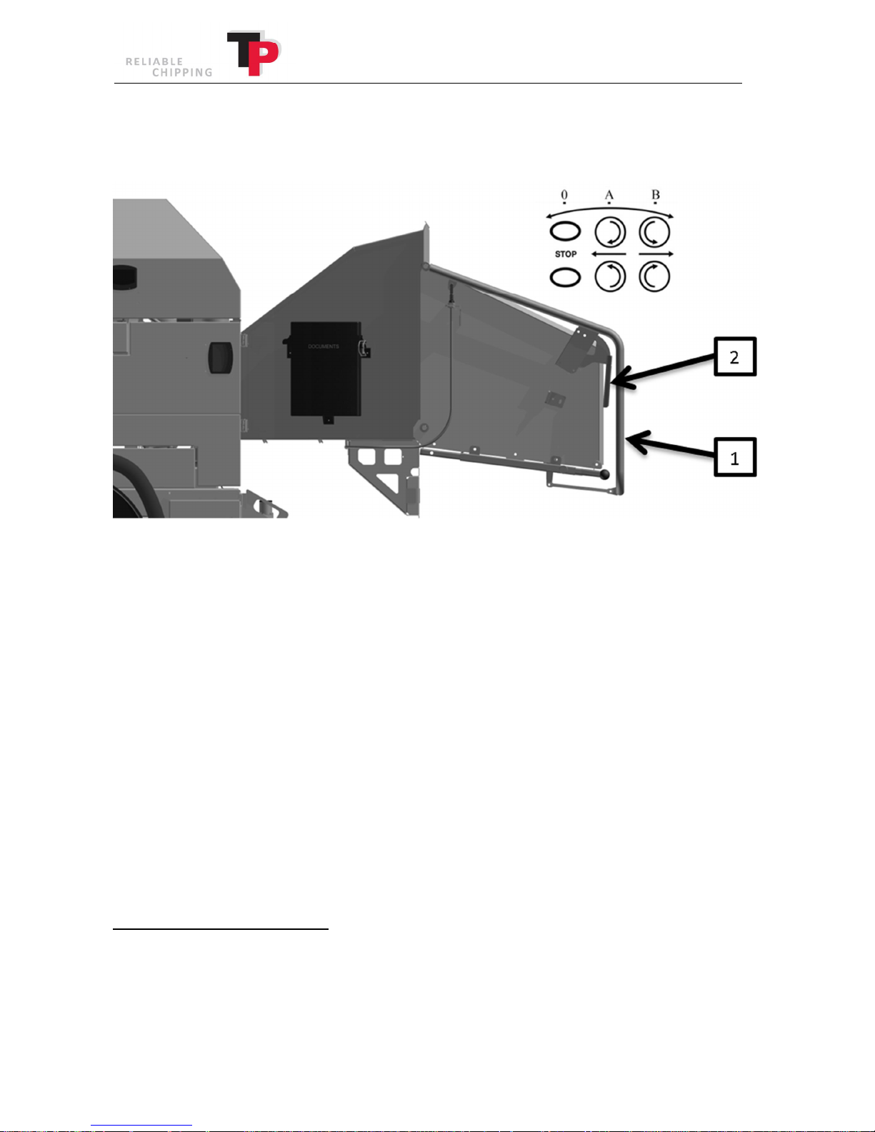
The wood chipper is equipped with two hydraulic rollers, which are controlled by a safety bar (1)
with a reset handle (2) and a TP CSC, which is programmed from the TP NAVIGATOR (see
instructions for TP NAVIGATOR in chapter 9).
Position A
The rollers rotate inwards and the material is drawn into the wood chipper.
Position B
The rollers rotate outwards and the material is pushed out of the wood chipper.
Position 0
The rollers stop.
When the safety bar has been pushed into position 0, the bar is locked. This is to ensure the rollers
are not unintentionally re-started.
To subsequently move the safety bar into position A or B, activate the reset handle.
During start-up, the safety bar must always be in position 0.
IN CASE OF POTENTIAL HAZARDS PUSH THE SAFETY BAR INTO THE STOP POSITION (position 0).
28 User Manual: TP 235 MOBILE / TP 275 MOBILE from date 01.12.2016
Page 29
Ó
Copyright 2015
8.2 TP VARIO SPOUT
TP 235 MOBILE and TP 275 MOBILE are equipped with TP VARIO SPOUT, which is a variable heightadjustable ejector spout, which is controlled via TP NAVIGATOR. TP VARIO SPOUT’s height is
controlled via TP NAVIGATOR (see chapter 9). NB: When operating the TP VARIO SPOUT, there
must not be any people inside the ejection area. At the same time, exercise caution when the TP
VARIO SPOUT is lowered down into the transport position, because the end of the ejector spout
reaches head height and this is a potential hazard.
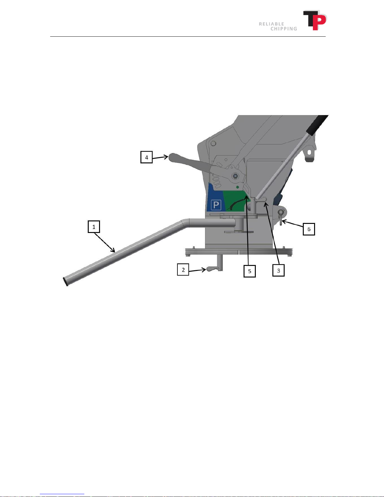
To turn the TP VARIO SPOUT use the handle (1), once the sliding bolt (2) is loosened. To re-secure
the TP VARIO SPOUT, lock the sliding bolt (2) in the desired position. The handle (1) can be turned
in the opposite direction for operating from the rear of the TP VARIO SPOUT. To do this, loosen
the sliding bolt (3) and turn the handle (1) 180 degrees until the sliding bolt (3) one again can lock
the handle (1).
The tilting spout is operated using the handle (4), which tilts away from the front position plate.
Next, move the handle (4) to the desired position and again release, the handle (4) subsequently
locks the tilting spout in the desired ejection position.
Before starting the wood chipper, the TP VARIO SPOUT must be raised to the operating height.
Before raising the ejector spout to operating height using TP NAVIGATOR the transport lock (6)
must be triggered. The transport lock (6) is released and locked in disengaged position by pulling
the sliding bolt on the transport lock (6) and then turn the sliding bolt 90 degrees
counterclockwise. Then the ejector spout can be raised to operating height using TP NAVIGATOR.
Note that the transport lock (6) automatically locks the ejector spout in transport position when
the ejector spout again is lowered to the transport position. The operating height is found by
looking at the indicator (5) positioned on the side of the ejector spout.
User Manual: TP 235 MOBILE / TP 275 MOBILE from date 01.12.2016 29
Page 30
Woodchip length
Disc
6 mm
8 mm
10 mm
12 mm
14 mm
16
TP 235 MOBILE
1160
17 22 28 33 39 44
TP 275 MOBILE
1372
20 26 33 40 46 52
Ó
Copyright 2015
Note the machine may only be operated when the indicator (5) is in the green area.
Once the wood chipper shall be parked or transported, lower the ejector spout all the way down
so that the indicator (5) is at the rear in the blue P area. The transport lock on TP VARIO SPOUT is
activated automatically when the ejector spout is lowered completely. Check before transport on
public roads that the transport lock (6) is engaged. During transport, the TP VARIO SPOUT must
always be within the machine's width and the sliding bolt (2) shall be locked.
8.3 In-feed speed
The wood chipper's in-feed speed is controlled by the TP CSC, which automatically regulates the
amount of oil to the feed rollers’ oil motors. TP CSC is programmed in TP NAVIGATOR, where the
desired chip length is entered (see instructions for TP NAVIGATOR in chapter 9). This ensures that
there is always the correct in-feed speed, independent of the disc's rpm.
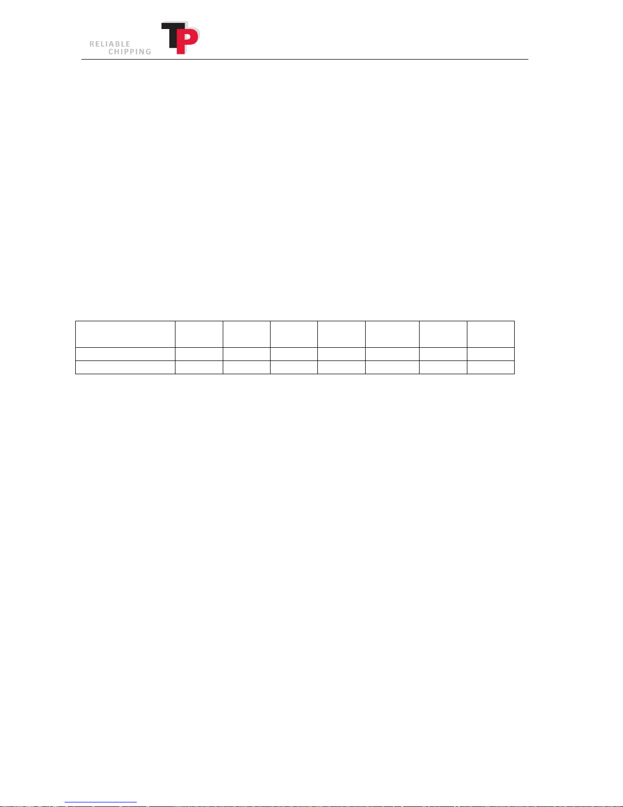
The table shown below provides the actual rpm of the feed rollers with the entered woodchip
length.
Model
rpm
rpm
rpm
rpm
rpm
rpm
rpm
8.4 Start-up and commissioning the wood chipper
Start the engine with the ignition key and let it run idle for a few minutes. Coupling of the wood
chipper's disc can be subsequently activated in TP NAVIGATOR (see instructions for TP NAVIGATOR
in chapter 9).
In TP NAVIGATOR, the start-up process is activated automatically, where the belts between the
wood chipper and the engine are automatically coupled at the same time as the engine's rpm is
increased from idle to nominal rpm. TP NAVIGATOR ensures that the belts have the correct
pre-tension.
Prior to the wood chipper starting, it must be ensured that the TP VARIO SPOUT is at the operating
height (see TP VARIO SPOUT in chapter 8).
30 User Manual: TP 235 MOBILE / TP 275 MOBILE from date 01.12.2016
Page 31
Ó
Copyright 2015
8.5 Connecting and disconnecting instructions
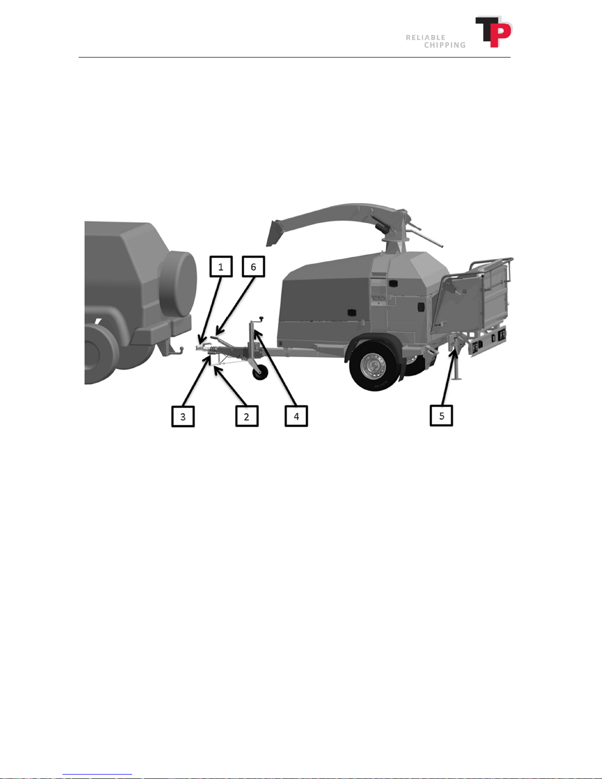
The wood chipper is a trailer hitched wood chipper and is designed to be fitted behind a vehicle
with a trailer hitch, as a coupling without requiring inspection. The wood chipper with trailer and
own engine is registered as a trailer tool.
REMEMBER: The wood chipper must always be coupled/uncoupled on a level surface!
Coupling with straight drawbar
1. Connect the wood chipper to the vehicle by securing the wood chipper's socket
coupling (1) onto the trailer hitch on the vehicle.
2. Fit the safety wire (2) to the trailer hitch.
3. Connect the 13-pin connector (3) to the vehicle.
4. Screw up the front jack (4).
5. Push down the rear support leg (5) and turn to the transport position.
6. Loosen the handbrake (6).
Uncoupling the wood chipper from the vehicle
To correctly uncouple the wood chipper, repeat the coupling procedure in reverse order.
User Manual: TP 235 MOBILE / TP 275 MOBILE from date 01.12.2016 31
Page 32
Ó
Copyright 2015
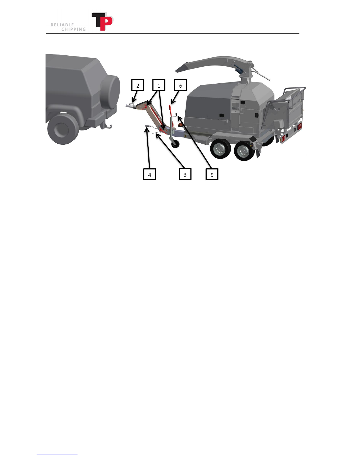
Coupling with a height-adjustable drawbar
1. Adjust the height-adjustable drawbar using the two turn joints (1), so that the wood
chipper is in a horizontal position when it is connected to the vehicle’s trailer hitch.
2. Connect the wood chipper to the vehicle by securing the wood chipper's socket/eye
coupling (2) onto the trailer hitch on the vehicle.
3. Fit the safety wire (3) to the trailer hitch.
4. Connect the 13-pin connector (4) to the vehicle.
5. Screw up the jack (5).
6. Loosen the handbrake (6).
Uncoupling the wood chipper from the vehicle
To correctly uncouple the wood chipper, repeat the coupling procedure in reverse order.
32 User Manual: TP 235 MOBILE / TP 275 MOBILE from date 01.12.2016
Page 33
Ó
Copyright 2015
8.6 Foldable funnel
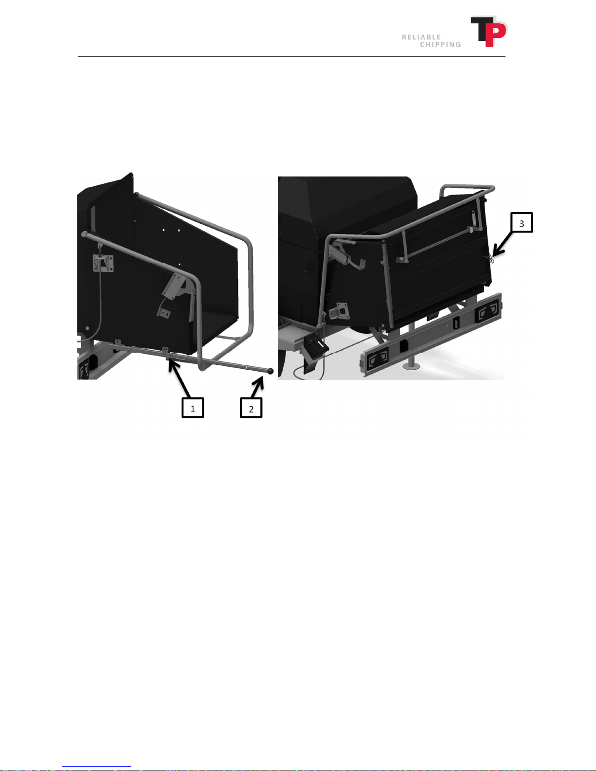
The aim of the foldable funnel is to minimise the total length of the mobile wood chipper during
transport and when storing it.
The foldable funnel must always be in the transport position during transport on public roads.
Transport position
1. Pull the sliding bolt (1) out while pulling the lever (2) out.
2. Now fold up the funnel by lifting the lever (2) (use both hands).
3. Once the funnel is folded up, secure it using the ring pin (3) in the right side.
4. Pull the sliding bolt (1) out and push the lever (2) back into its starting position. The funnel
is now in the transport position.
Operating position
To put the foldable funnel into the operating position, repeat the transport position procedure in
reverse order.
User Manual: TP 235 MOBILE / TP 275 MOBILE from date 01.12.2016 33
Page 34
Ó
Copyright 2015
8.7 TP TURNTABLE
If the wood chipper is equipped with the TP TURNTABLE, the wood chipper can rotate
independently of the trailer frame. This is an advantage where the operator wishes to feed the
wood chipper from the side rather than from the rear.
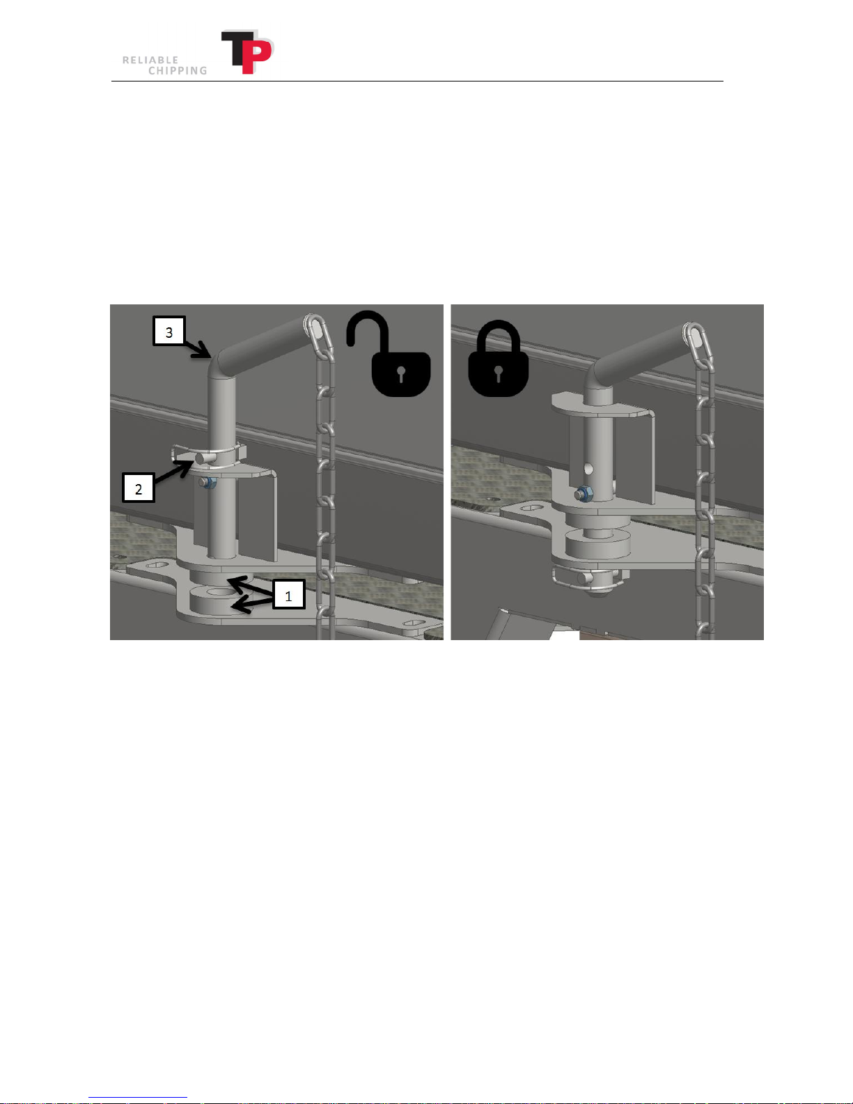
8.7.1 Transport lock
The transport lock always be in the transport position during transport on public roads.
Transport position
1. Ensure the wood chipper is in position with the front at the ball and socket coupling and
that the two locking eyes (1) are aligned.
2. Take the pin (2) out of the top hole in the locking ring (3).
3. Take hold of the locking ring (3) move it all the way to the bottom.
4. Put the pin (2) in the bottom hole in the locking ring (3). The turntable is now locked in the
transport position.
Operating position
To unlock the transport position, follow the transport position procedure in reverse order.
34 User Manual: TP 235 MOBILE / TP 275 MOBILE from date 01.12.2016
Page 35
Ó
Copyright 2015
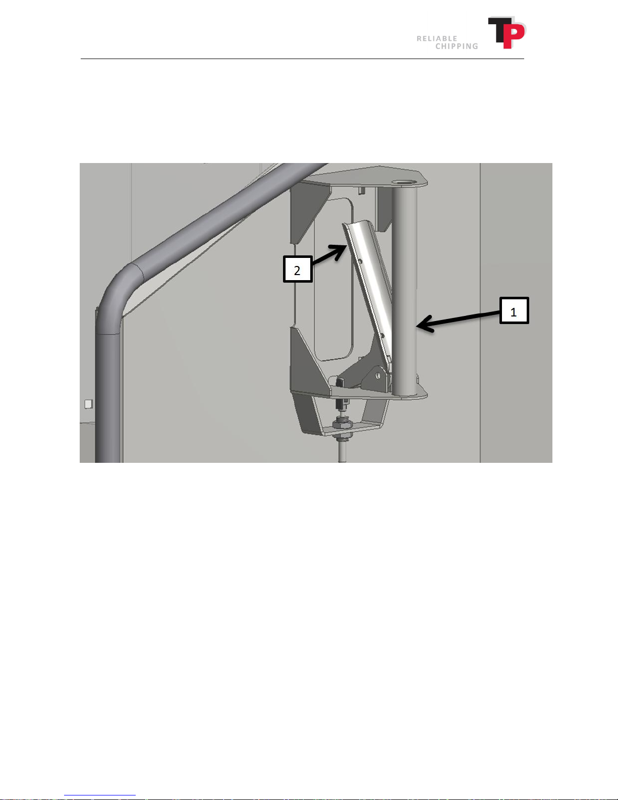
8.7.2 Use of the TP TURNTABLE
There is a handle positioned on the right side of the funnel, which is used to turn the funnel to the
desired position.
Before using the TP TURNTABLE, ensure that the transport lock has been unlocked.
1. Take hold of the handle (1) press down the release (2) all the way to the bottom.
2. Next, turn the funnel to the desired position by either pushing or pulling on the handle
(use both hands).
3. Once the funnel is in the desired position, let go of the release (2). Remember to ensure
that the release is locked before the wood chipper starts to be used.
User Manual: TP 235 MOBILE / TP 275 MOBILE from date 01.12.2016 35
Page 36

Ó
Copyright 2015
9 TP NAVIGATOR
TP NAVIGATOR is a fully functional control system with a touchscreen and associated key.
The system controls and monitors a large number of the wood chipper's instruments.
9.1 Key
The key is used the same way any other ignition key with ignition lock is used, and has the
following positions:
First position = Off
Second position = On
Third position = Start
The key is equipped with an ignition lock, so that if an attempt has been made to start the wood
chipper, the key must be turned to the off position, before another attempt at ignition can be
made.
The key functions as an emergency stop for the machine. If a dangerous situation arises, switch off
using the key!
9.2 Operating TP NAVIGATOR
TP NAVIGATOR is equipped with a touchscreen, which is operated by touch. Because the screen
functions using resistive technology, the operator can wear gloves.
Navigate in TP NAVIGATOR by:
· Pressing the buttons directly on the screen.
· Browse between different functions by swiping a finger across the screen.
36 User Manual: TP 235 MOBILE / TP 275 MOBILE from date 01.12.2016
Page 37
Ó
Copyright 2015
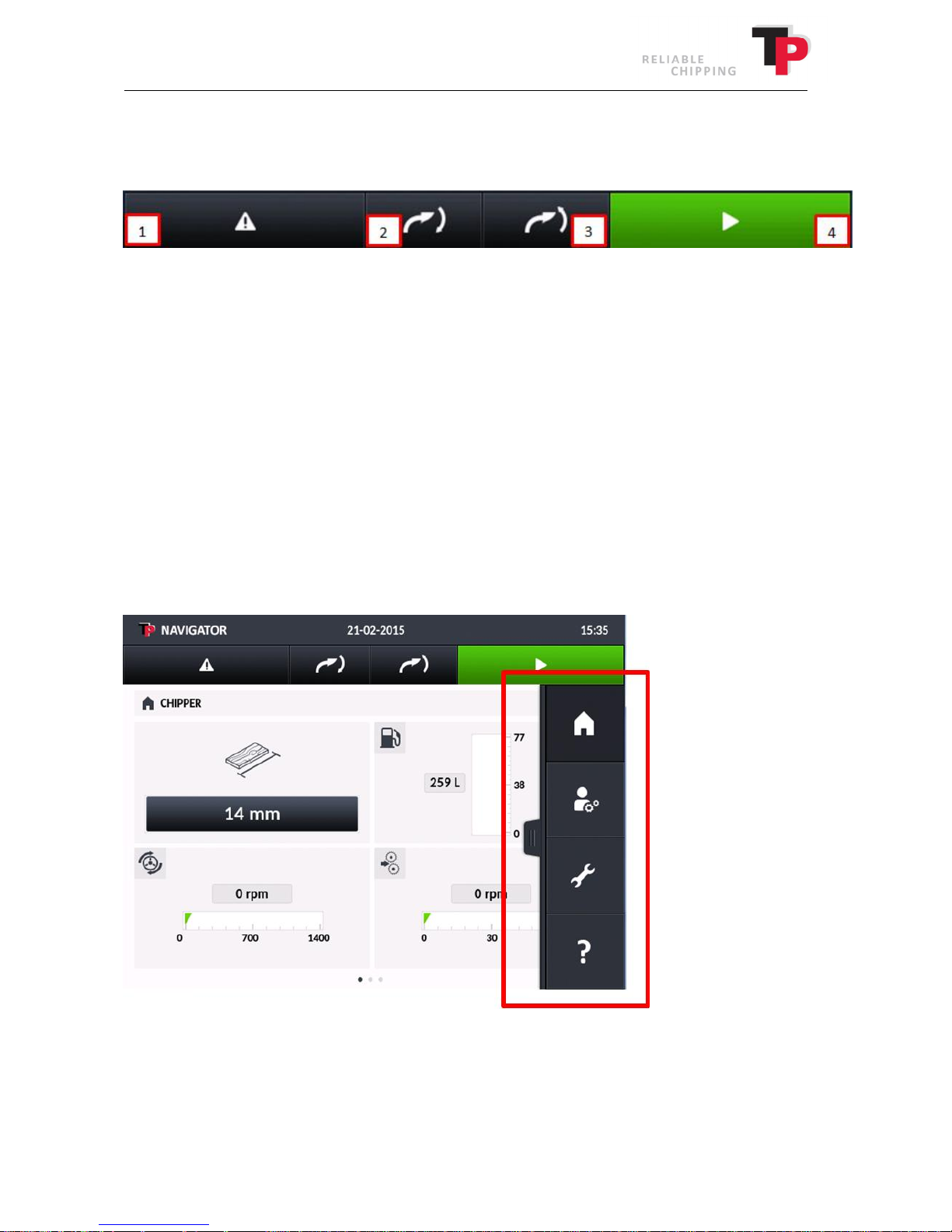
9.3 Top menu
The top menu is the stationary menu, which is positioned at the top of the screen.
1. Warning indicator
If there is a problem with the wood chipper, the warning indicator will be red. Press the
indicator to see the failure.
2. TP VARIO SPOUT down (Note that the transport lock as described under TP VARIO SPOUT
in Sec. 8, automatically engages when the ejector spout is lowered to the lowest position)
3. TP VARIO SPOUT up (Note that the transport lock as described under TP VARIO SPOUT in
Sec. 8, must be triggered in order to raise the ejector spout from the lowest transport
position)
4. Start/stop of wood chipper
9.4 Page menu
Tapping once the top right side of the screen with a finger will cause the side menu to enter the
screen from the right. The menu is always accessible and contains the following sub-menus:
User Manual: TP 235 MOBILE / TP 275 MOBILE from date 01.12.2016 37
Page 38
Ó
Copyright 2015
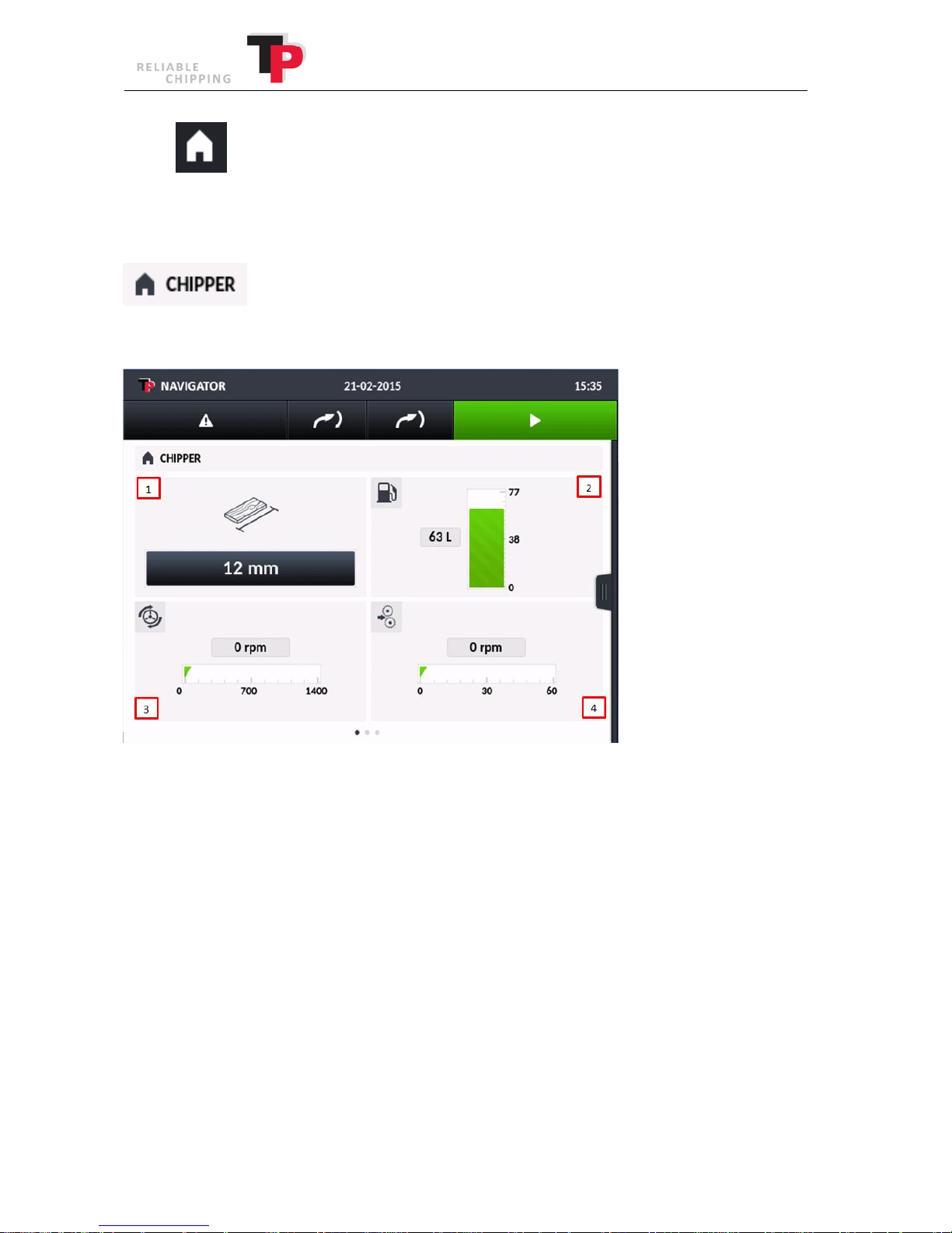
9.4.1 HOME
Pressing HOME will always return the user to the start screen. The start screen contains three
different pages: CHIPPER, ENGINE and SERVICE. The three pages are explained below.
The CHIPPER page is the first page the operator sees when the wood chipper is switched on or
when HOME is pressed. This page contains all of the information about the wood chipper.
The CHIPPER page displays the following four instruments:
1. TP CHIP SIZE CONTROLLER (TP CSC).
TP CSC indicates the desired size of the wood chips. TP CSC automatically adjusts the roller
rpm to achieve the desired woodchip size. Press the number to choose another size of
woodchip than the current size.
2. Fuel level is in litres.
3. The disc's actual rpm.
4. The rollers' actual rpm
38 User Manual: TP 235 MOBILE / TP 275 MOBILE from date 01.12.2016
Page 39
Ó
Copyright 2015
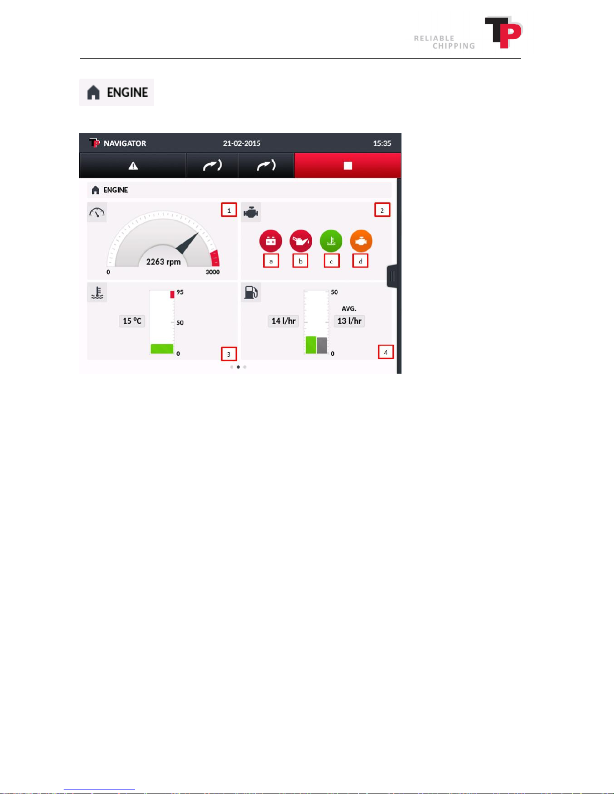
ENGINE page is on the other page in HOME. This page shows information about the engine.
The ENGINE page displays the following four instruments:
1. The engine's actual rpm.
2. Engine lights.
Green = OK, Red/orange = not OK.
a. Battery requires charging.
b. Oil pressure too low.
c. Engine temperature too high.
d. Engine failure.
3. The engine's actual temperature.
4. Actual and average fuel consumption.
User Manual: TP 235 MOBILE / TP 275 MOBILE from date 01.12.2016 39
Page 40
Ó
Copyright 2015
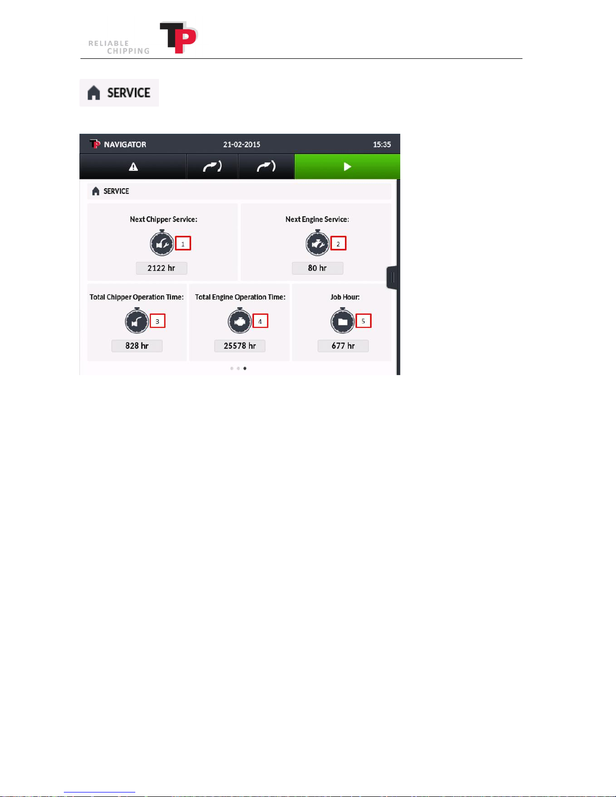
The SERVICE page is the third page in HOME. This page shows information about service routines.
The SERVICE page displays the following five instruments:
1. Total number of working hours before the next service of the wood chipper.
The service interval can be reset. See PROTECTED SETTINGS.
2. Total number of working hours until the next service of the engine.
The service interval can be reset. See PROTECTED SETTINGS.
3. Total number of work hours for the wood chipper unit.
4. Total number of work hours for the engine.
5. Job hour counter.
40 User Manual: TP 235 MOBILE / TP 275 MOBILE from date 01.12.2016
Page 41
Ó
Copyright 2015
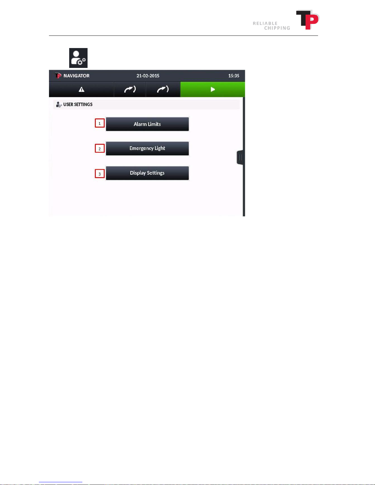
9.4.2 USER SETTINGS
Here the user has the opportunity to adjust a number of settings.
1. Set when the TP NAVIGATOR must warn of low diesel level.
Recommended value is 10 l.
2. Only for TP TURNTABLE models. The user can switch on/off the rotary light.
The light is used to warn other road users that the wood chipper has turned across the
driving lane when wood chipping along a busy road.
3. Calibrate and set the touchscreen's light strength.
User Manual: TP 235 MOBILE / TP 275 MOBILE from date 01.12.2016 41
Page 42
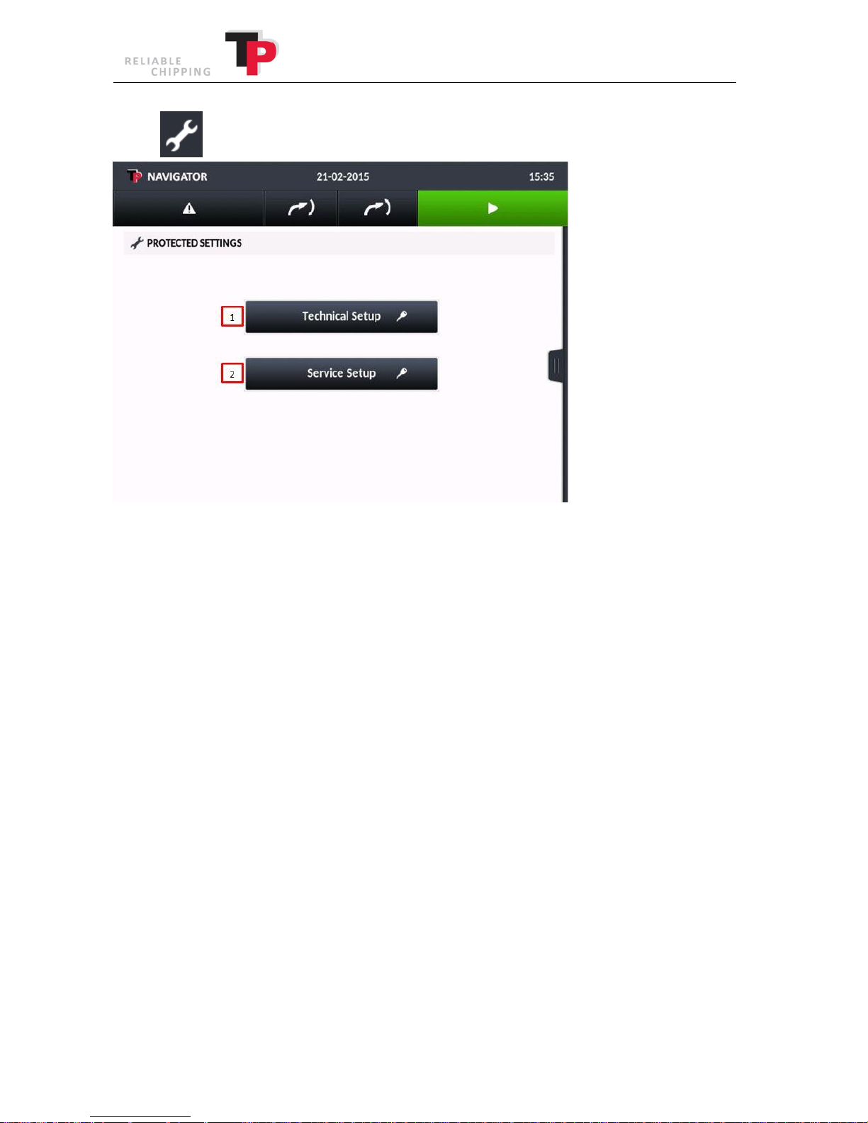
9.4.3 PROTECTED SETTINGS
Ó
Copyright 2015
This menu allows technical or service personnel access to the settings on the wood chipper. Both
menus are password protected.
1. Access only for authorised personnel! The technical parameters related to the wood
chipper's function can be adjusted.
2. The service counter for the engine and the wood chipper unit can be reset. In addition, the
counter for the next service can be set. To ensure the 3-year warranty remains valid, all of
the service intervals must be complied with! The code is 9320.
42 User Manual: TP 235 MOBILE / TP 275 MOBILE from date 01.12.2016
Page 43
Ó
Copyright 2015
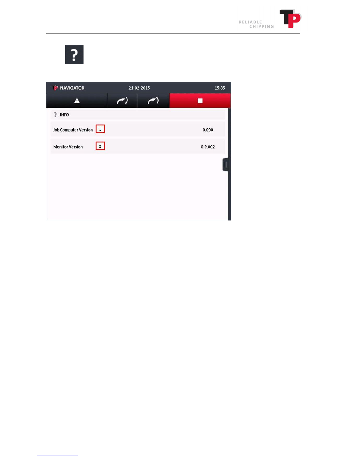
9.4.4 INFO
This menu contains information about the current software version used in the wood chipper.
1. Version no. of software in the de-central box
The de-central box is located in the engine compartment.
2. Version no. of control system in the TP NAVIGATOR screen.
10 Maintenance
The wood chipper must be inspected every day. This includes opening the disc housing and
checking the feed, disc, knives, counterknives, triangle scraper and square scrapers. This will
ensure that unexpected stoppages are avoided and prolong the life of the wood chipper.
When carrying out maintenance and repairs, the wood chipper must be stopped, and the wood
chipper key must be removed from the ignition before the rotor housing is opened. (see opening
and closing of disc housing chapter). 7). In addition, the wood chipper must also be positioned on
a level, flat surface when carrying out maintenance and repairs.
User Manual: TP 235 MOBILE / TP 275 MOBILE from date 01.12.2016 43
Page 44
Interval=
> hours
10* 6
50 6
250 6
1000
1
equipment)
Lubricate disc main bearings
2
X
2
3
2
Lubricate safety switches
X
7
2
Lubricate the TP EASY
SERVICE
2
X
Reverse/replace triangle scrapers, square scrapers and scrapers
X
5
Replace facing plate in top disc housing (extra equipment)
X
Check ejector wings for wear and tear
X
Model type
Standard oil type
Bio-oil (optional)
8
Quantity in l
TP 275 MOBILE
Hydraway HVXA 46
Hydraway SE 46 HP
28 l
Ó
Copyright 2015
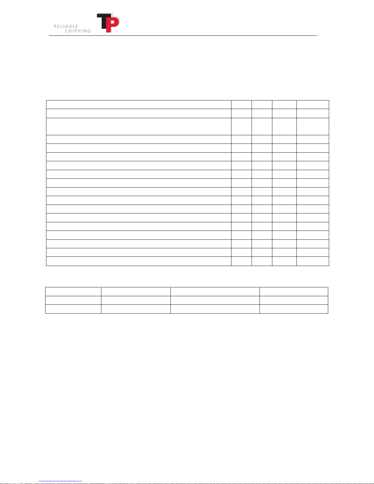
10.1 Maintenance schedule for wood chipper
X = for each stated time interval
(X) = Only for the first time
* = or once a week
Check safety bar's function
Check the knives and counterknives (and sliver breaker - extra
Tighten all bolts and nuts (X) (X)
X
X
6
Lubricate the fixed roller bearings
Lubricate the revolving roller bearings
Lubricate TP VARIO SPOUT
4
Replace the return filter for the hydraulic pump
Lubricate the revolving roller foot
X
X
X
(X) X
X
Reverse/replace counterknife X
Change hydraulic oil
6
X
Check casing for wear and tear X
10.2 Hydraulic oil table
TP 235 MOBILE Hydraway HVXA 46 Hydraway SE 46 HP 28 l
1
Always execute before use! Pay particular attention to ensuring that the rollers do not rotate when the safety bar is in the stop
position.
2
Lubricate two lubrication nipples with Uniway Li62 or equivalent lubricant.
In case of light use: Lubricate after 12 months.
3
Lubricate lubrication nipples with Uniway Li62 or equivalent lubricant.
In case of light use: Lubricate after 12 months.
4
Safety switch at the bonnet, fuel hatch, and at the cover above the infeed, must be lubricated with spray lube or chain lube.
If the safety switch is defective, it must be changed immediately.
5
Drain the hydraulic oil and fill with new oil. See above for the hydraulic oil table for oil type and amount.
6
If fitted, change the facing plate in the top disc housing as necessary.
7
Replace after 12 months.
8
The interval between changing oil can be extended by using biodegradable oil, which can be purchased as extra equipment.
44 User Manual: TP 235 MOBILE / TP 275 MOBILE from date 01.12.2016
Page 45
Interval=> hours
10 6
250 6
500 6
1000
1500
5000
inter
-
radiator
Check/clean the air filter (external and internal)
1
X
Check alternator's belt tension
2
X
Check fuel hose
X
3, 4
3, 4
Replace fuel filter
3, 4
X
4
4
4
1
Ó
Copyright 2015
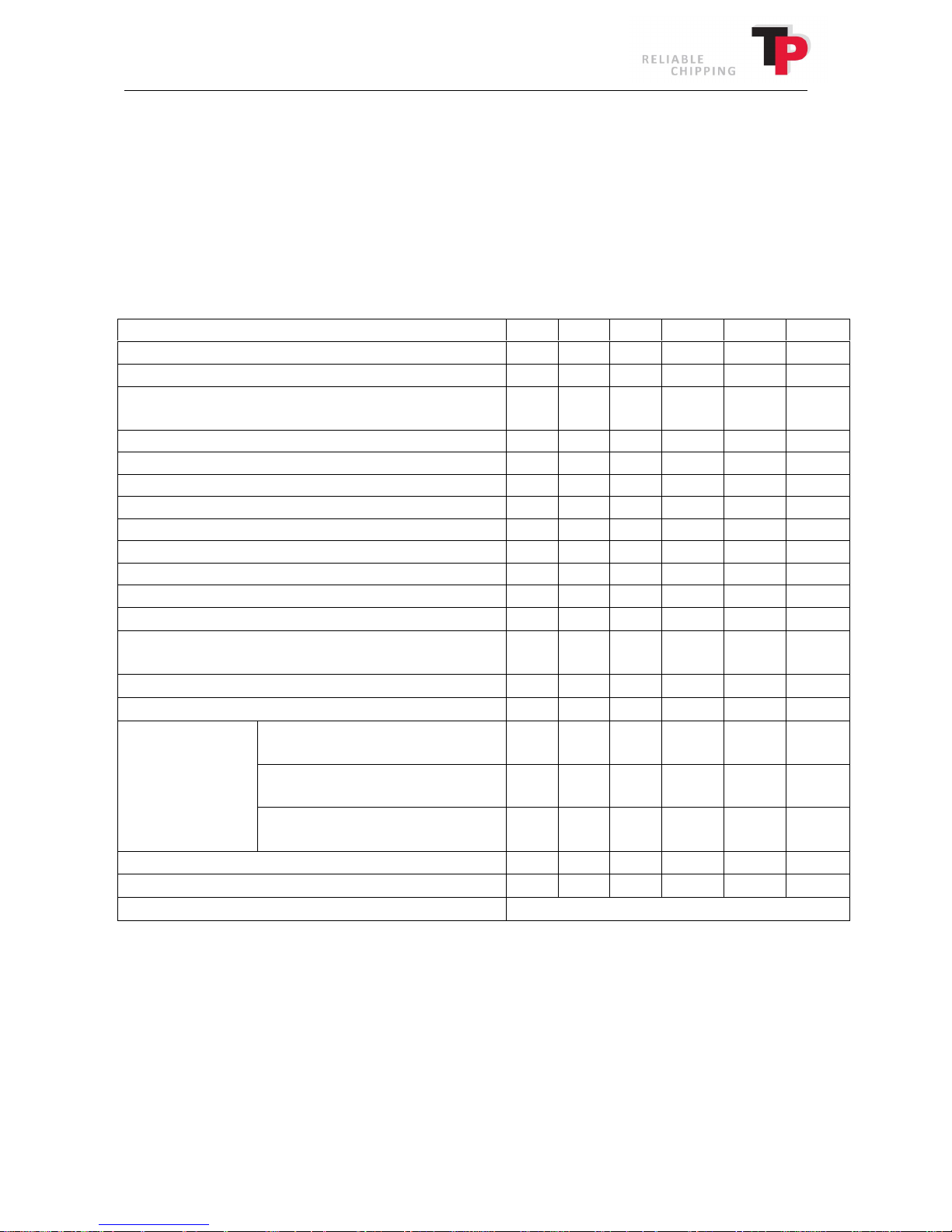
10.3 Maintenance schedule for engine
For the correct execution of the maintenance of the engine, refer to the engine manual. The
engine manual contains precise instructions for how the engine in your TP wood chipper is best
serviced.
X = for each stated time interval
(X) = Only for the first time
6
Check oil level X
Check the coolant condition X
Check/clean filter in front of the radiator and
1
X
Check/clean radiator and inter-radiator1 X
6
6
Check rubber hoses at air intake and radiator X
Replace engine oil
Replace oil filter
X
Replace coolant
Replace the hose to the intake manifold (hose
between the air filter and intake manifold)
4
X
X
X
Replace radiator hoses4 X
Replace fuel hoses4 X
Alternator belt
Check the engine starter
Check the alternator
Replace external air filter
1
The length of time between a check of the filter elements may vary depending on the conditions the engine operates
in. The air filter must be cleaned and replaced more frequently in very dusty conditions.
2
Not Poly-V belt type.
3
In case of light use: Replace after 12 months.
4
For replacement, refer to the engine manual.
5
In case of light use: Replace after 36 months.
Standard alternator belt
(trapezium shape)
4, 5
Poly-V belt (unclean working
environment)
4
Poly-V belt (clean working
environment)
4
X
X
X
X
X
After six, check when the filter was cleaned.
User Manual: TP 235 MOBILE / TP 275 MOBILE from date 01.12.2016 45
Page 46
TP 235 MOBILE
KDI 1903
TCR SAE 5W-
30 CJ
-4
8.9 l
10.4 Engine oil level
Ó
Copyright 2015
Model type
Engine type
Oil type:
(maximum level)
With oil filter
Oil capacity
TP 275 MOBILE KDI 2504 TCR SAE 5W-30 CJ-4 11.5 l
10.5 Hydraulics
The wood chipper is filled at the factory with mineral hydraulic oil as standard (bio-oil may be
purchased as extra equipment). See hydraulic oil table in chapter 10. When replacing the oil, use
the same type of oil or an oil with equivalent specifications. Do not mix oils of different
types/brands.
Old hydraulic oil must be handed in to the municipal receiving station.
Replacing of hydraulic oil and return filter
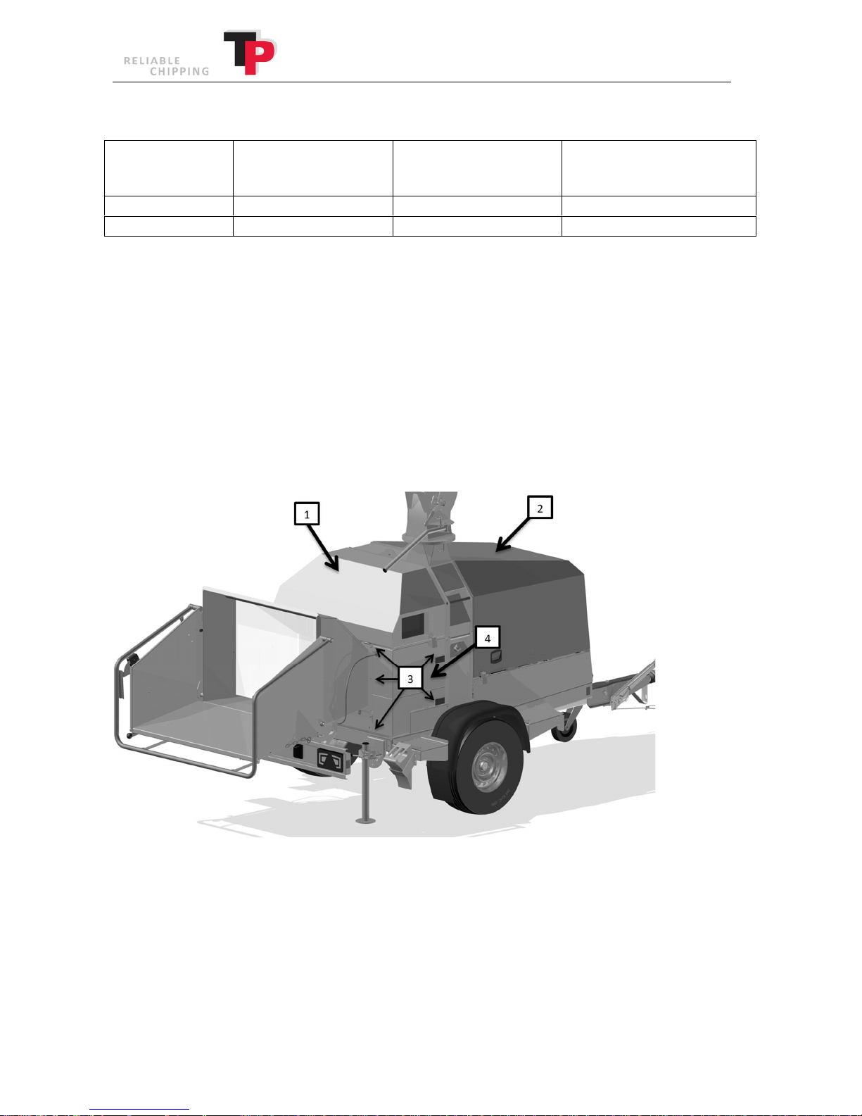
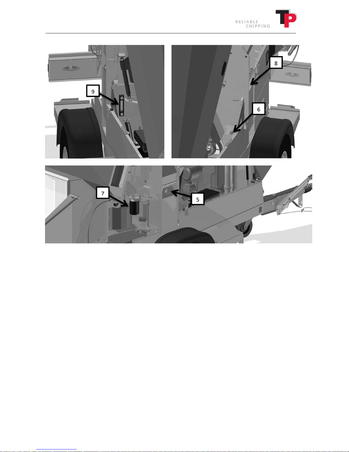
1. Open the cover above the in-feed (1) and the bonnet (2). The cover above the in-feed and
bonnet is locked using an external catch on each side.
2. Loosen the five bolts (3) and remove the side cover (4), which opens up access to the
return filter.
46 User Manual: TP 235 MOBILE / TP 275 MOBILE from date 01.12.2016
Page 47
Ó
Copyright 2015
3. Remove the filler neck (5).
4. Unscrew the drain plug (6) and capture the oil in a container for suitable disposal.
5. When the tank is almost empty, suck the tank empty using an oil suction device.
6. Replace the return filter (7) with a new filter.
7. Screw the drain plug (6) back on.
8. Remove the breather plug (8) and slowly fill with new hydraulic oil. Fill the oil until the oil
level is at the middle of the level glass (9).
9. Lastly, fit the filler neck (5), breather plug (8), side cover (4) re-using the five bolts (3).
User Manual: TP 235 MOBILE / TP 275 MOBILE from date 01.12.2016 47
Page 48
Ó
Copyright 2015
10.6 Knives
The wood chipper is fitted with four knives.
The knives must always be changed as a set. The knives belong together in sets, also when they
are ground so that they are always of equal width. If the knives are not of equal width, the disc will
be out of balance, which will lead to unnecessary strain on the bearings and vibrations in the
whole wood chipper.
Replacing the knives
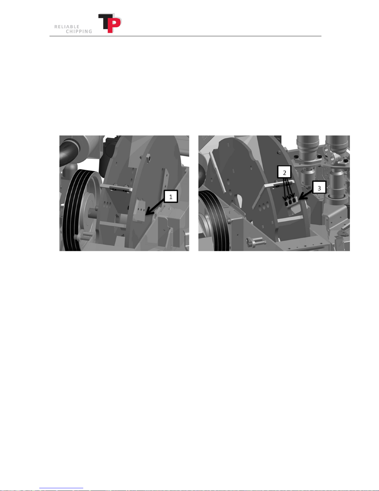
1. Open the disc housing as described in chapter 7.
2. Remove the bolts (2) that hold the knives and clamping plates (3)/sliver breaker securely to
the disc.
3. Remove the knives and sharpen/replace.
4. Carefully clean the knives (1), clamping plates (3)/sliver breaker and contact faces.
5. When fitting the knives (1), the bolts (2) must be lightly oiled (m=0.125), i.e. light oil, WD 40
or an equivalent product. Do not use copper grease, MoS2 or similar low friction grease.
6. Check that the distance between the knife edge and the counterknife is set correctly to D
(see chapter 10). Check all of the knives.
7. Tighten the bolts (2) to 110 Nm / 11 KPm. Use a torque spanner for this purpose (available
as extra equipment).
8. Finally, close the disc housing as described in chapter 7.
48 User Manual: TP 235 MOBILE / TP 275 MOBILE from date 01.12.2016
Page 49
Ó
Copyright 2015
Sharpening knives
It is very important for the quality of woodchip that the knives are sharp. They must be checked at
least once a day. The grinding interval of the knives can be prolonged by grinding them regularly
with a carborundum stone.
The grinding process must be wet grinding with a header. Never use an angle grinder or a similar
tool for grinding the knives.
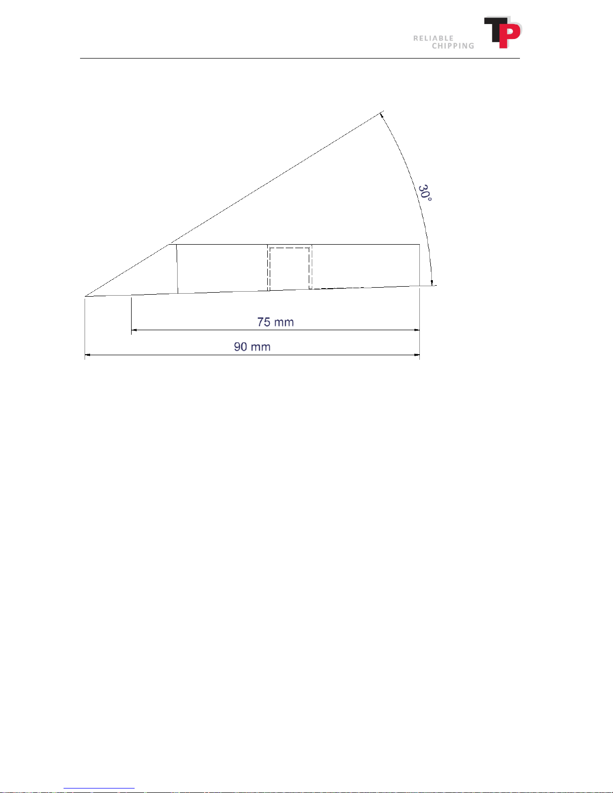
When grinding knives, ensure that the width of the knives in the set are uniform. Their widths
must be the same to keep the disc in balance. This means that the knives must always to be
ground in sets. The knives must not be ground down to a width of less than 75 mm. After that they
must be discarded.
The edge of the knives must be ground at an angle of 30°
User Manual: TP 235 MOBILE / TP 275 MOBILE from date 01.12.2016 49
Page 50
Ó
Copyright 2015
10.7 Counterknife
The counterknife in the wood chipper is used by the knife to cut the wood. The counterknife must
have a sharp edge otherwise the wood will bend and the cutting face become frayed. The wood
chipper is equipped with a vertical counterknife in one side of the in-feed and a horizontal
counterknife in the base. The horizontal counterknife has two cutting edges and therefore can be
reversed.
Changing the counterknife
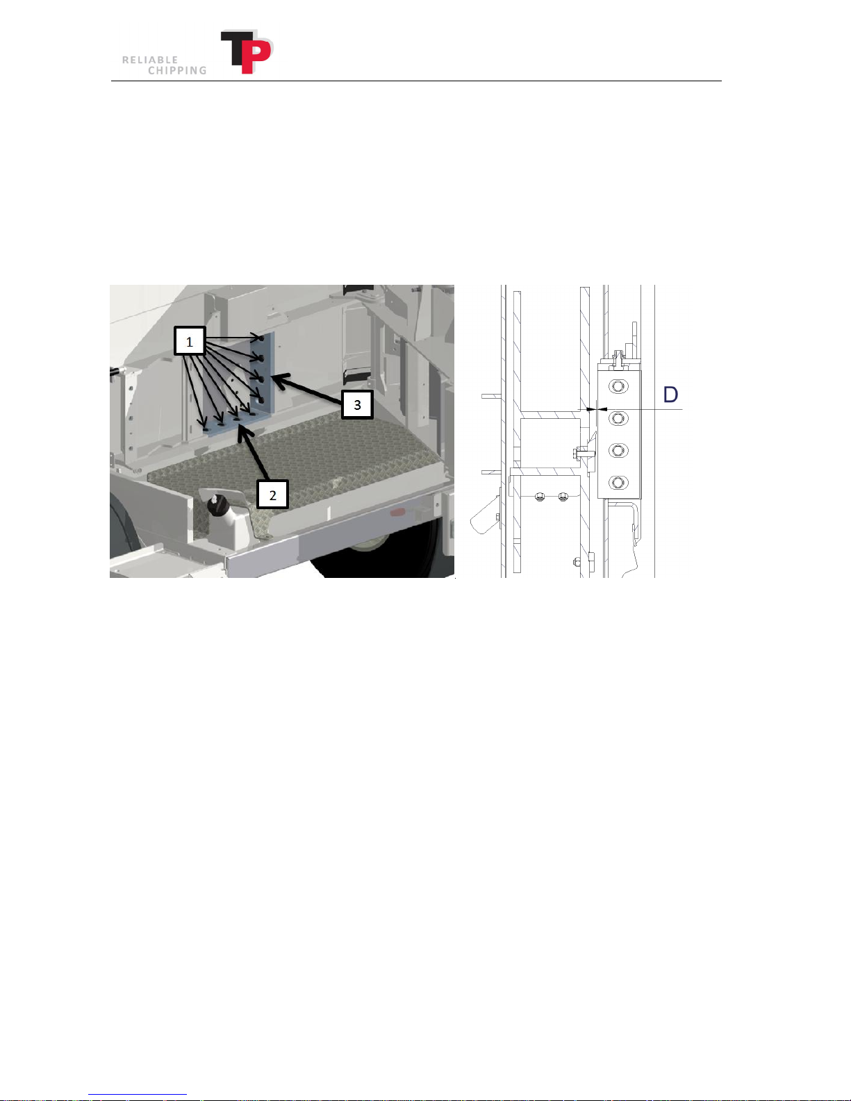
D = 1.5 mm
1. Open the TP EASY SERVICE as described in chapter 7.
2. Remove the bolts (1) that hold the respective counterknife (2, 3) in place.
3. Take out the counterknife (2,3) and reverse/replace.
4. Carefully clean the counterknife (2,3) and contact surface.
5. Re-fit the counterknife (2,3) and adjust the distance between the knife edge and the
counterknife to distance D using a precision feeler gauge (see illustration above).
6. The bolts in the horizontal (2) and vertical (3) counterknife must be tightened to 110 Nm /
11 KPm Use a torque spanner for this purpose (available as extra equipment).
7. Once the counterknives (2, 3) have been reversed or replaced and all of the bolts (1) have
been tightened, close the TP EASY SERVICE as described in chapter 7.
8. Finally, close the disc housing as described in chapter 7.
50 User Manual: TP 235 MOBILE / TP 275 MOBILE from date 01.12.2016
Page 51
Ó
Copyright 2015
10.8 Square and triangle scrapers and scrapers
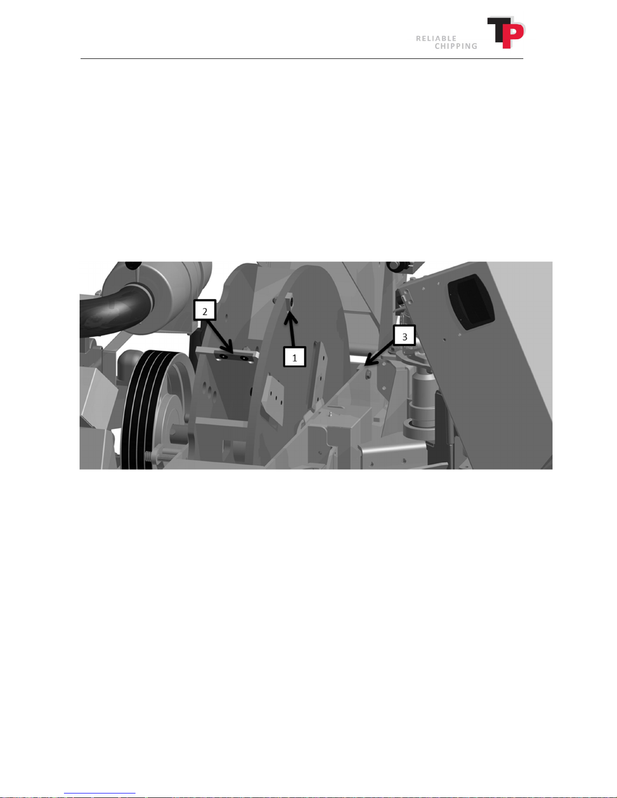
The wood chipper is equipped with two square scrapers on the disc and a triangle scraper in the
disc housing.
The purpose of the square and triangle scrapers is to remove material that can get stuck by the
knives.
At the same time, the square scraper removes material which falls off in front of the disc.
This reduces fuel consumption and wear on the casing.
A square scraper can be reversed once, before being replaced, while the triangle scraper should
always be replaced when it is worn. The square scrapers belong together as a set and must always
be replaced in pairs.
Changing the square and triangle scrapers
1. Open the disc housing as described in chapter 7.
2. Remove the two square scrapers (1) and the four scrapers (2) and triangle scrapers (3).
3. Reverse the square scraper (1) 180 degrees around the bolt hole, so that the worn corners
face in towards the disc's centre of rotation. If both corners or sides are worn, replace the
scrapers.
Reverse the scraper (2) 180 degrees so that the worn side faces into the disc's centre of
rotation. If both sides are worn, replace the scrapers.
The triangle scraper (3) cannot be reversed and must always be replaced.
4. Clean the contact surfaces and the square and triangle scrapers (1, 3)/scrapers (2) and
re-fit.
5. Finally, close the disc housing as described in chapter 7.
User Manual: TP 235 MOBILE / TP 275 MOBILE from date 01.12.2016 51
Page 52
Ó
Copyright 2015
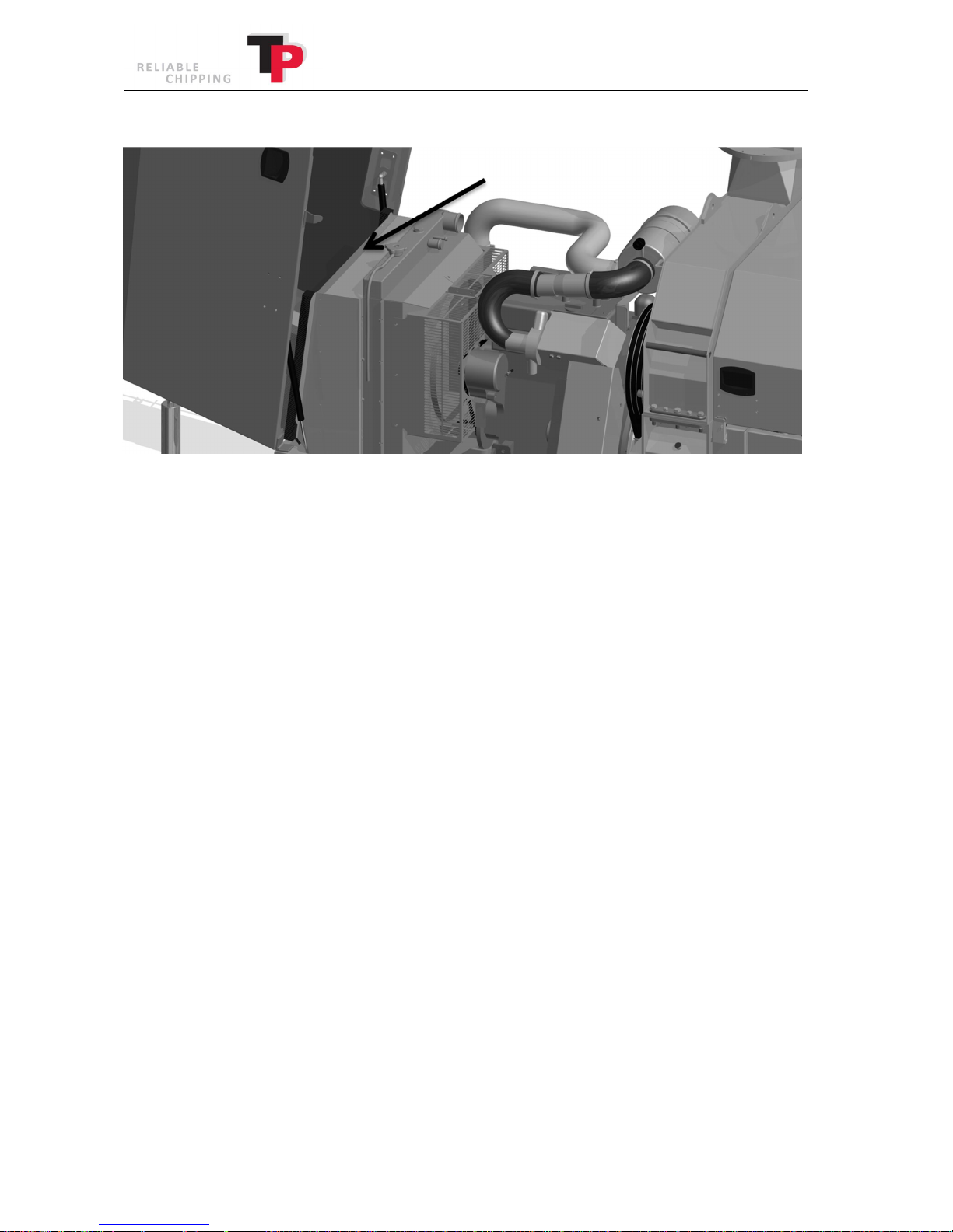
10.9 Cleaning the filter in front of the radiator
There is a fitted filter in front of the radiator that collects particles that are too big to pass through
the actual radiator. The arrow on the illustration above indicates the positioning of the filter.
Cleaning procedure:
1. Stop the wood chipper and the engine. Open the bonnet and lift the filter out of the
“track”.
2. Filter cleaning procedure:
· Knock the dust off carefully by hitting the frame of the filter on the ground or on a
piece of wood.
· Clean using compressed air from the "cooling side".
· Clean using a high-pressure cleaner. Only used for extreme clogging and must be
dried before starting the wood chipper.
Generally you get fewer stoppages by ensuring the wind does not blow dust from the ejector
spout directly into the cooler.
52 User Manual: TP 235 MOBILE / TP 275 MOBILE from date 01.12.2016
Page 53
Ó
Copyright 2015
10.10 Related to battery
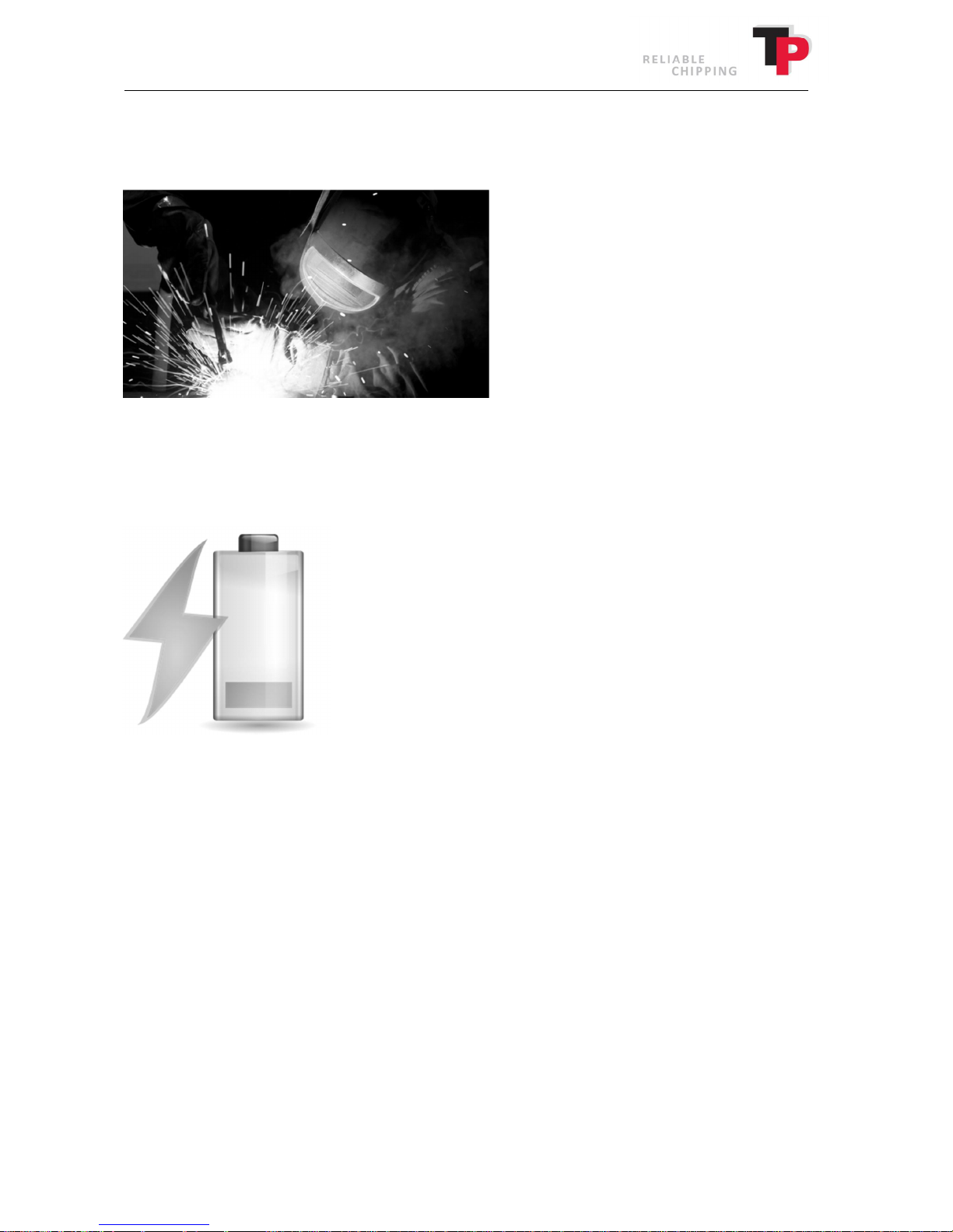
Welding
When welding on the wood chipper, the cable that is connected to the battery's negative pole
must always be disconnected (look for the " - " symbol on the battery).
Charging the battery
If the battery is to be charged from another power source, the cable that is connected to the
battery's negative pole must always be disconnected (look for the " - " symbol on the battery).
User Manual: TP 235 MOBILE / TP 275 MOBILE from date 01.12.2016 53
Page 54

Ó
Copyright 2015
11 Hydraulics
11.1 Replacing hydraulic hoses
If a hydraulic hose bursts, it must be replaced. All TP hydraulic hoses are stamped with a product
number in the hose's fitting. This product number is used to identify the hydraulic hoses.
When replacing hydraulic hoses, always use original TP hoses.
54 User Manual: TP 235 MOBILE / TP 275 MOBILE from date 01.12.2016
Page 55
Ó
Copyright 2015
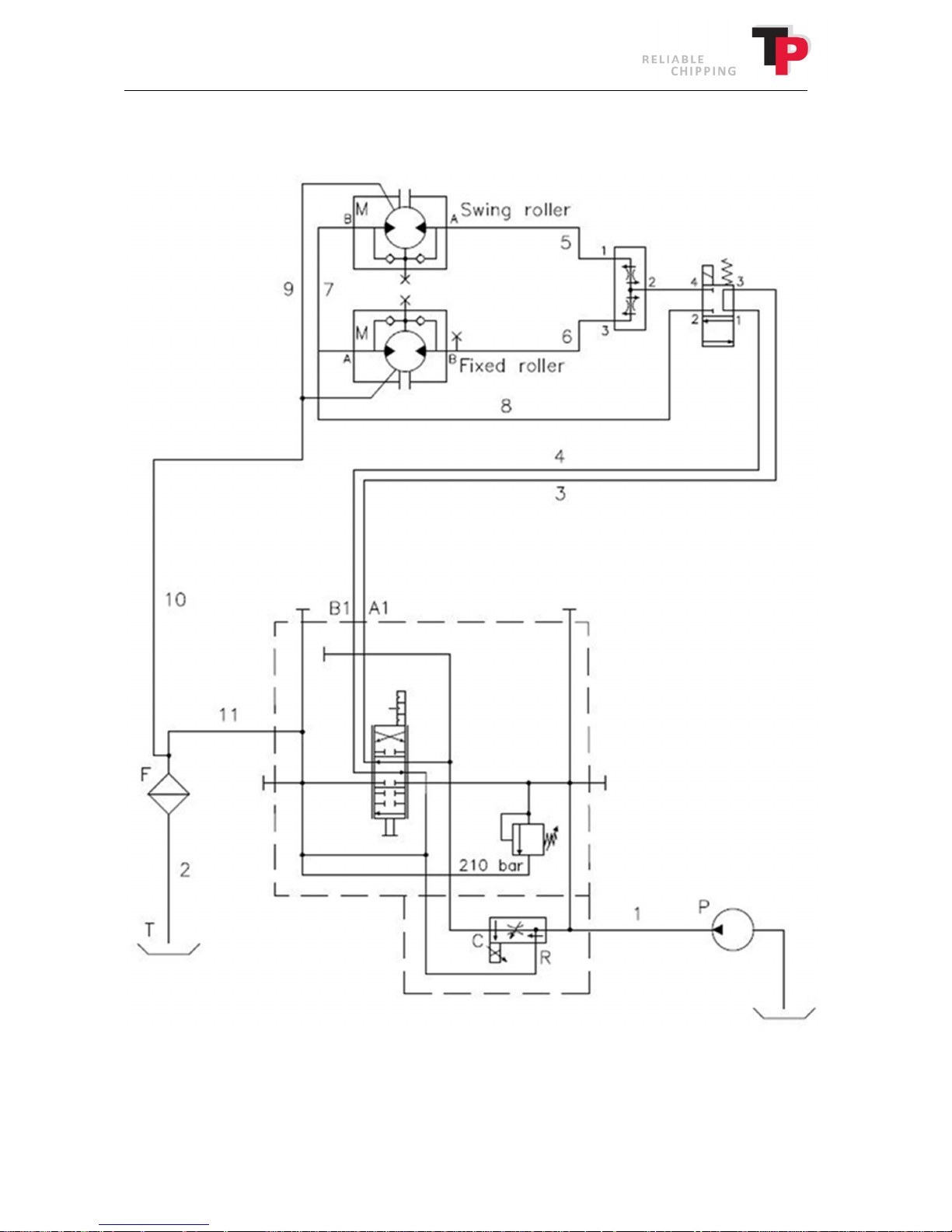
11.2 Hydraulics diagram, TP 235 MOBILE
User Manual: TP 235 MOBILE / TP 275 MOBILE from date 01.12.2016 55
Page 56
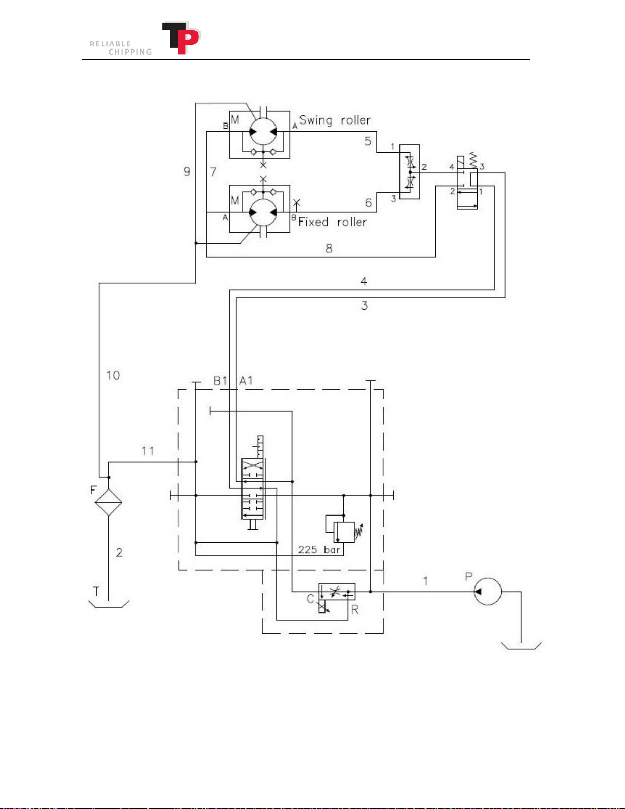
11.3 Hydraulics diagram, TP 275 MOBILE
Ó
Copyright 2015
56 User Manual: TP 235 MOBILE / TP 275 MOBILE from date 01.12.2016
Page 57
Ó
Copyright 2015
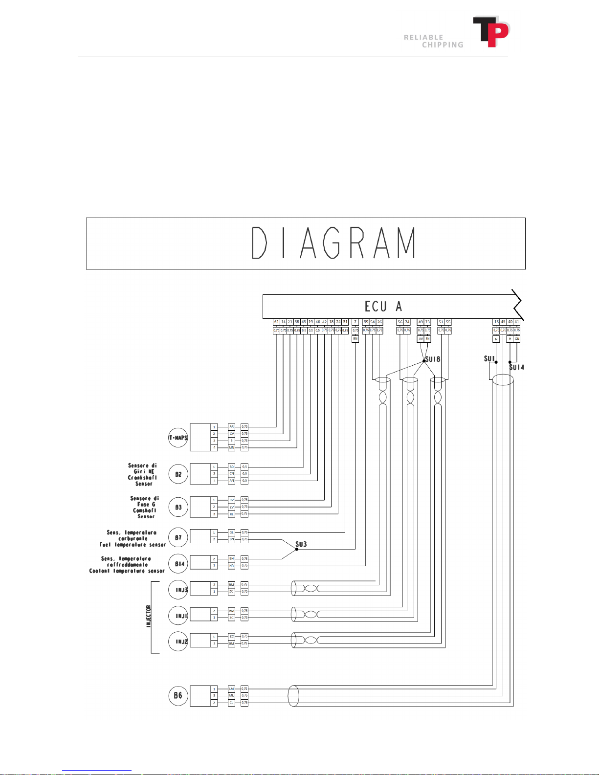
12 Electrical diagram TP 235 and TP 275
The electrical diagram for both the engine and TP NAVIGATOR is shown here. For the engine both
in diagram form and the full power line. TP NAVIGATOR has the diagram and overview of the
connections.
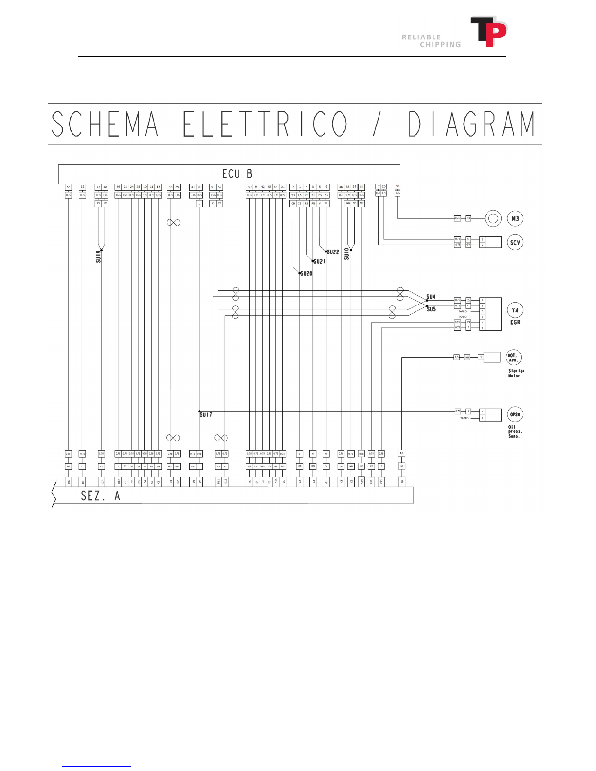
The diagrams and power line are so comprehensive that they are divided into several images, with
interfaces where appropriate. NB: SEZ. A = Molex connector, connects the TP NAVIGATOR and
engine.
12.1 Diagram engine
SEZ. A is divided into several illustrations. Part 1 is shown below.
User Manual: TP 235 MOBILE / TP 275 MOBILE from date 01.12.2016 57
Page 58
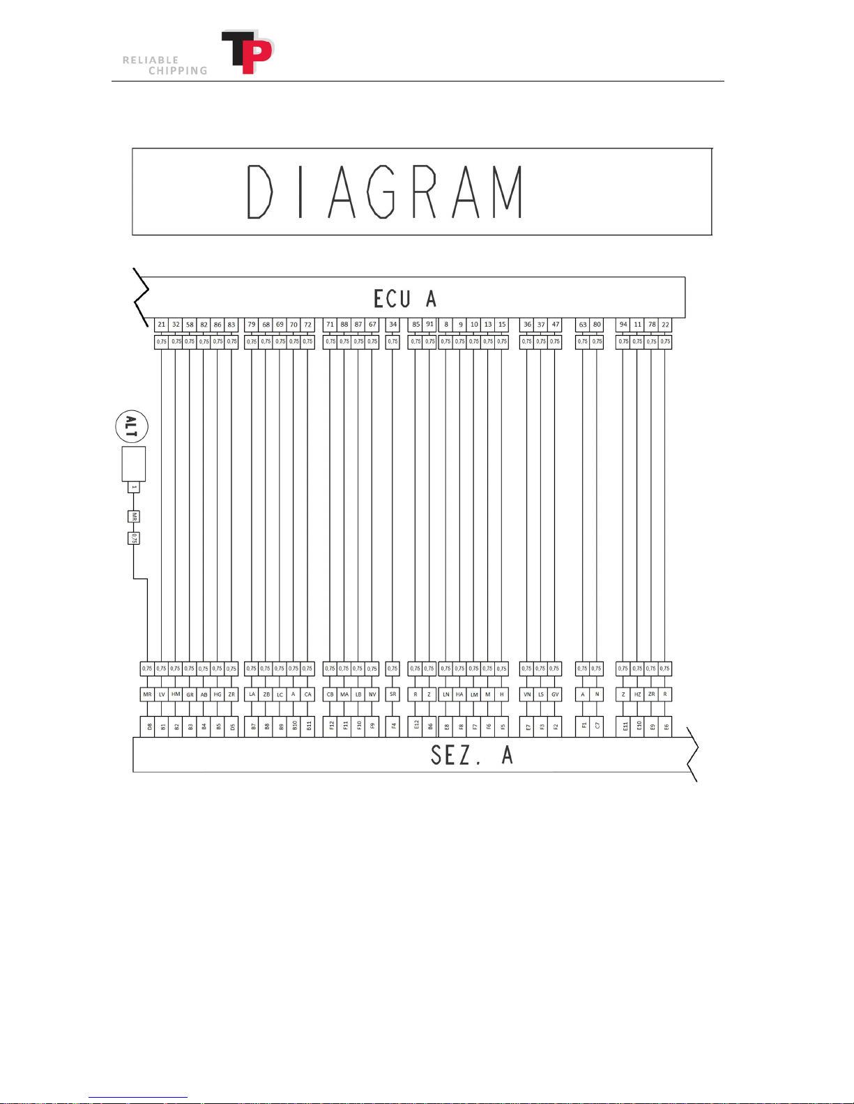
Part 2 of engine diagram:
Ó
Copyright 2015
58 User Manual: TP 235 MOBILE / TP 275 MOBILE from date 01.12.2016
Page 59
Ó
Copyright 2015
Part 3 of engine diagram.
User Manual: TP 235 MOBILE / TP 275 MOBILE from date 01.12.2016 59
Page 60
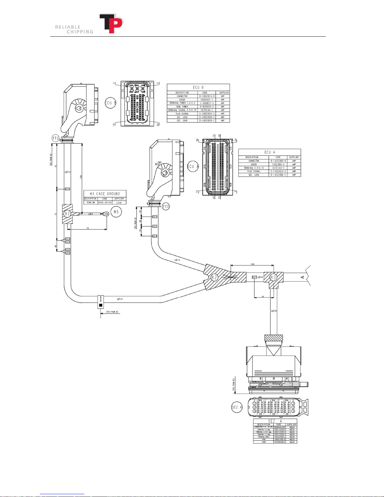
12.2 Power line on engine
The power line from the engine is also divided into several illustrations. Part 1:
Ó
Copyright 2015
60 User Manual: TP 235 MOBILE / TP 275 MOBILE from date 01.12.2016
Page 61
Ó
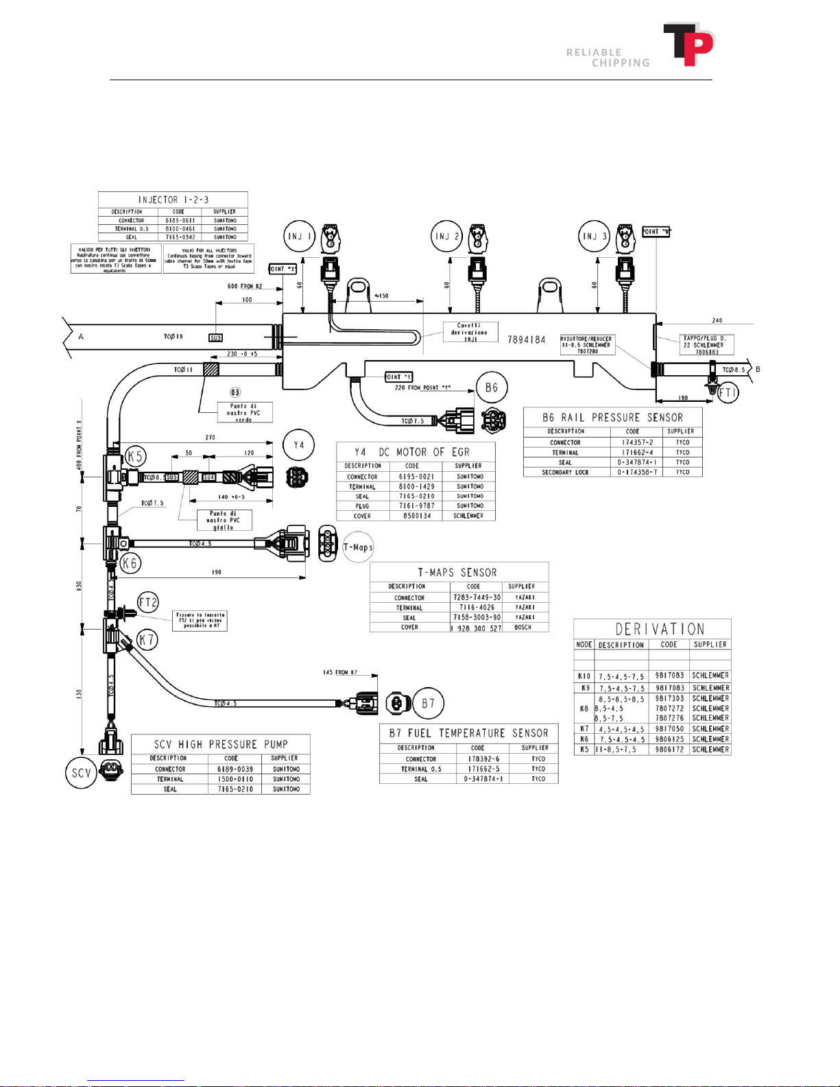
Copyright 2015
Part 2 power line engine. The only difference on the TP 235 and TP 275 is that the TP 235 has 3 INJ
(injector, injector valves) and TP 275 has 4 INJ (injector, injector valves). The model shown is a TP
235. The last injector valve on the TP 275 is positioned following on from the other injection
valves.
User Manual: TP 235 MOBILE / TP 275 MOBILE from date 01.12.2016 61
Page 62
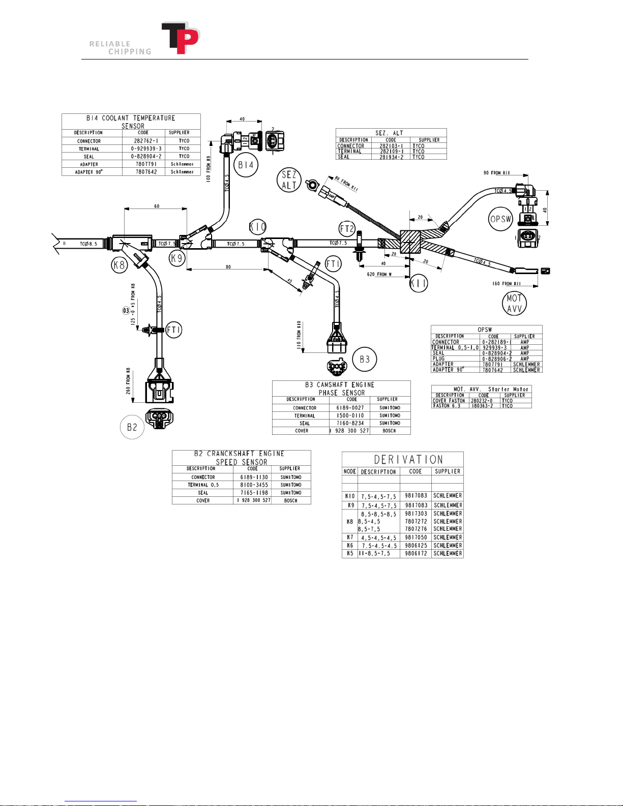
Part 3 power line engine:
Ó
Copyright 2015
62 User Manual: TP 235 MOBILE / TP 275 MOBILE from date 01.12.2016
Page 63
Ó
Copyright 2015
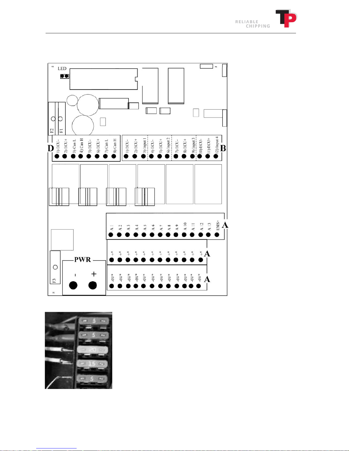
12.3 Diagram TP NAVIGATOR
Diagram of de-central job computer (Jobmini)
Diagram of fuses.
Ignition fuse
EGR valve fuse
Main relay fuse
Start relay fuse
Screen and OBD2 fuse
User Manual: TP 235 MOBILE / TP 275 MOBILE from date 01.12.2016 63
Page 64
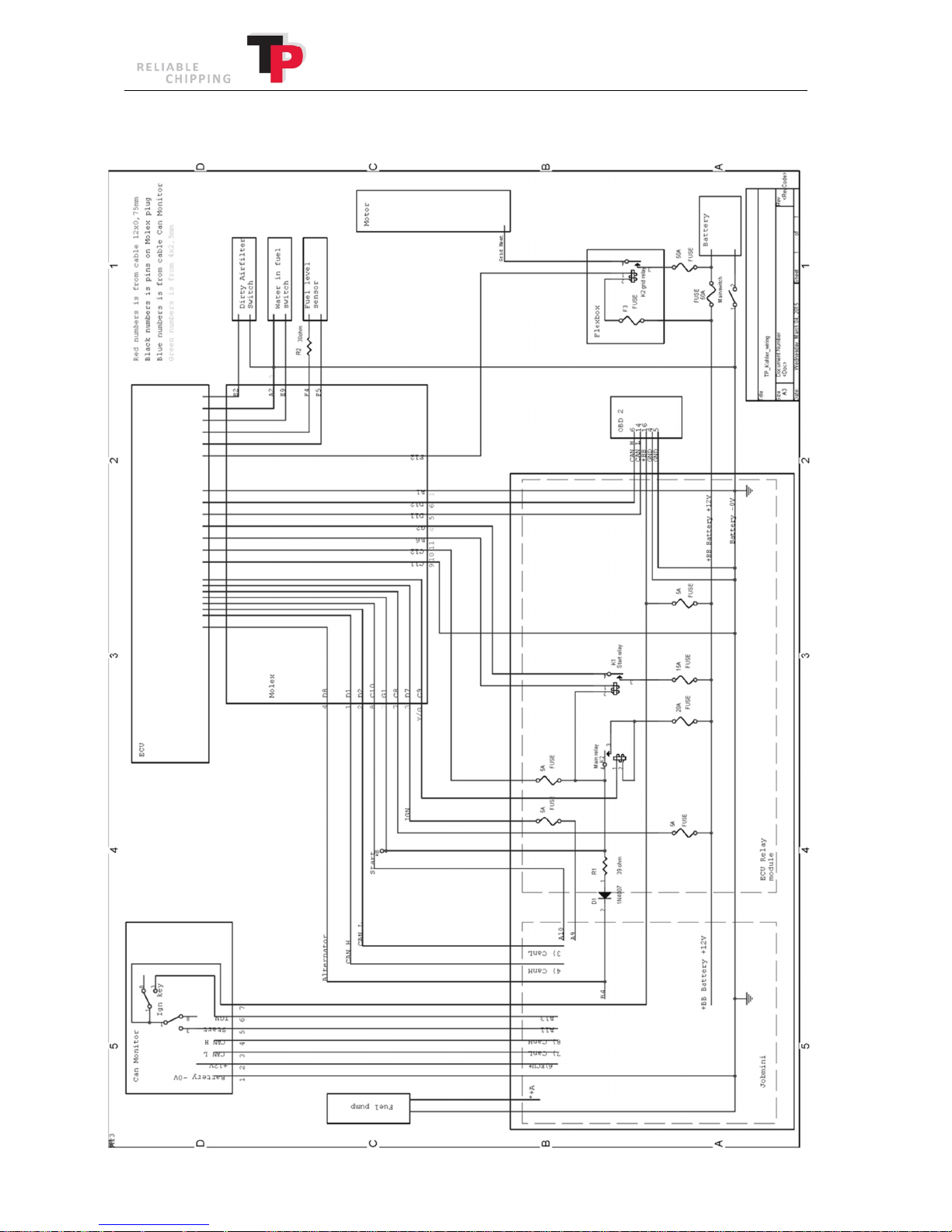
Connections diagram TP NAVIGATOR.
Ó
Copyright 2015
64 User Manual: TP 235 MOBILE / TP 275 MOBILE from date 01.12.2016
Page 65
Ó
Copyright 2015
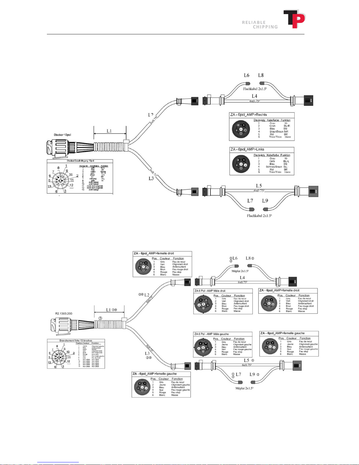
12.4 Electrical diagram trailer
12.4.1 TP 235/275 MOBILE
12.4.2 TP 235/275 T MOBILE
User Manual: TP 235 MOBILE / TP 275 MOBILE from date 01.12.2016 65
Page 66
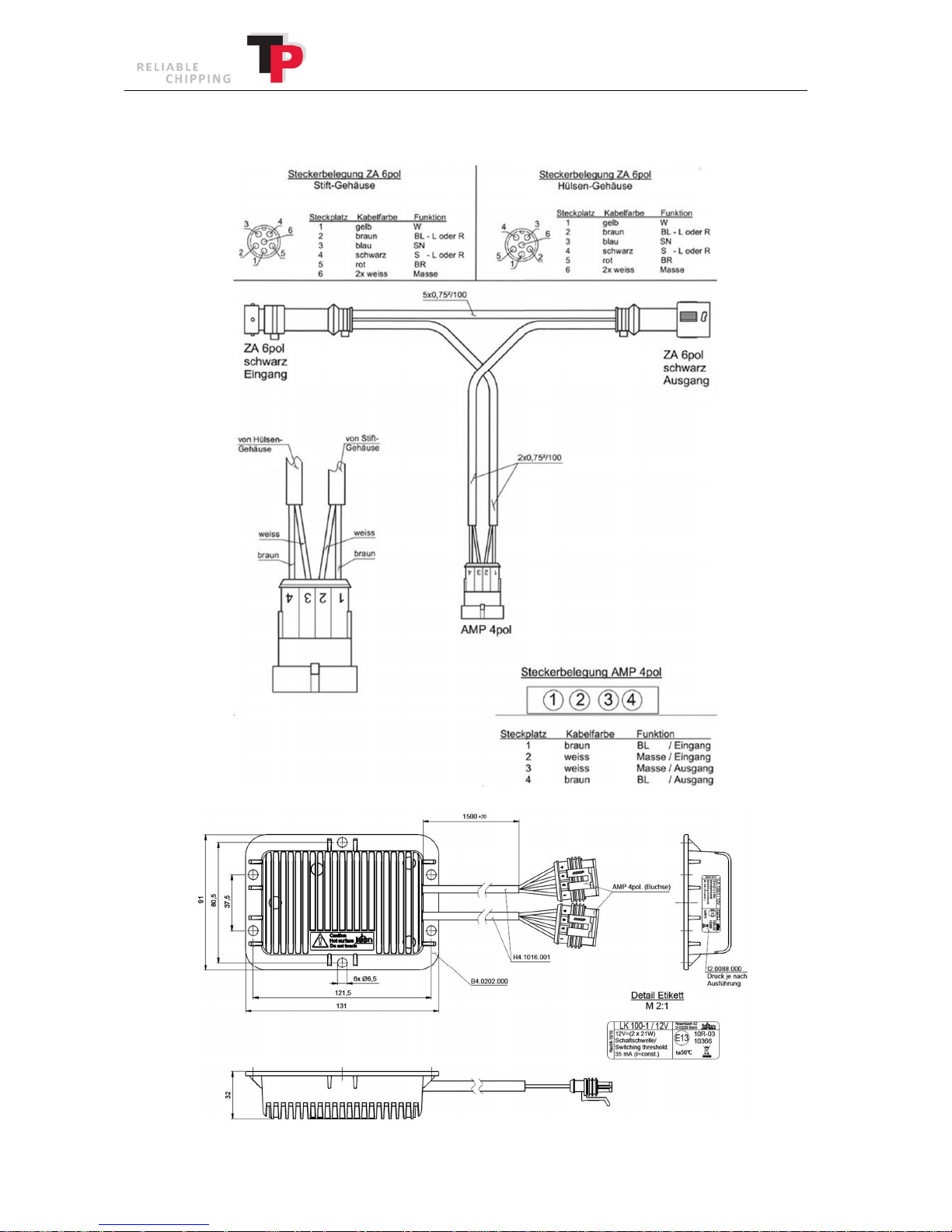
12.4.3 Indicator relay TP 235/275 MOBILE og TP 235/275 T MOBILE
Ó
Copyright 2015
66 User Manual: TP 235 MOBILE / TP 275 MOBILE from date 01.12.2016
Page 67
Chip Size Controller valve coil defect.
Check for voltage on valve coil. (4
–
12 V)
The oil engine is worn or damaged.
Replace the oil engine.
The facing plate in the top part
Remove the facing plate from the top part
Ó
Copyright 2015
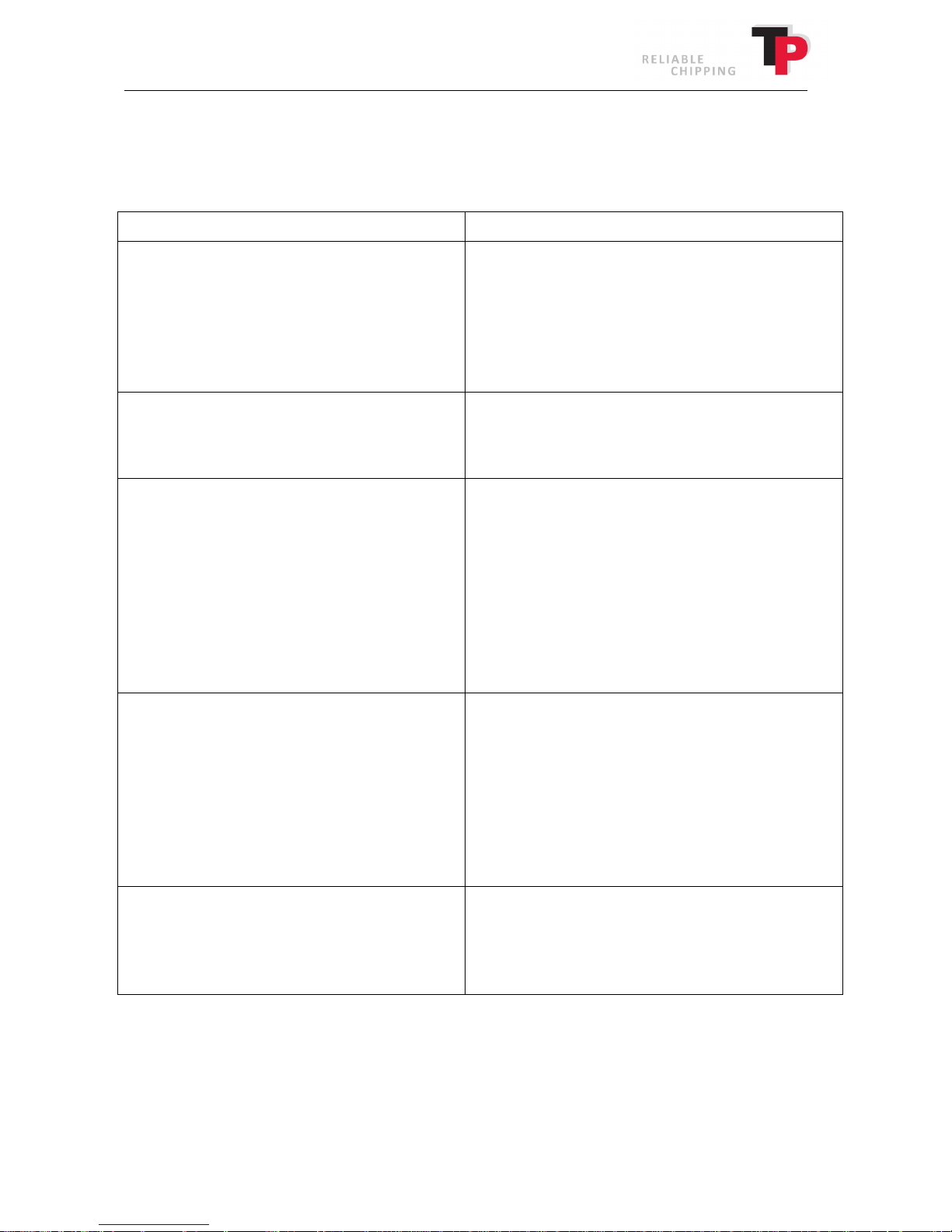
13 Troubleshooting
Check possible causes before contacting the supplier.
Problem/Possible cause Solution
The rollers do not turn:
The operation bar is in the 0 position.
The rollers are blocked.
Bypass valve to rpm monitor is dirty.
rpm monitor is not connected to the rollers.
Put the operation bar in the A position
Clean below and behind the blocked roller(s).
Clean the bypass valve.
Check rpm value on disc/engine.
The rollers rotate too slowly:
Chip size set for two low a value.
Not enough oil in the hydraulics system.
Pulling power in the rollers is impaired:
The hydraulic oil is becoming too hot.
The hydraulic filter is blocked.
The pressure control valve at the roller speed
regulator is dirty.
Hydraulic oil is worn.
The oil pump is worn or damaged.
Unsatisfactory woodchip quality:
The knives are blunt.
The counterknife is worn.
The knives are worn down too far.
The distance between knife and counterknife is
too big.
Sliver breaker not mounted or worn.
Facing plate is not fitted.
Poor ejection of woodchip:
Not enough driving power.
Square and triangle scrapers/scrapers are worn.
Increase chip size in TP NAVIGATOR.
Fill up with hydraulic oil.
Let the wood chipper cool down while checking
why.
Replace the hydraulic filter.
Clean the pressure control valve.
Change the hydraulic oil.
Replace the hydraulic pump.
Sharpen the knives.
Reverse/replace counterknife.
Replace the knives.
Adjust the distance between the knives and
counterknife.
Fit or replace the sliver breaker.
Fit facing plate.
The engine does not provide sufficient power.
Replace the square and triangle scrapers/scrapers
User Manual: TP 235 MOBILE / TP 275 MOBILE from date 01.12.2016 67
Page 68

14 Warranty terms wood chipper
Refer to the delivered warranty certificate.
Ó
Copyright 2015
68 User Manual: TP 235 MOBILE / TP 275 MOBILE from date 01.12.2016
Page 69
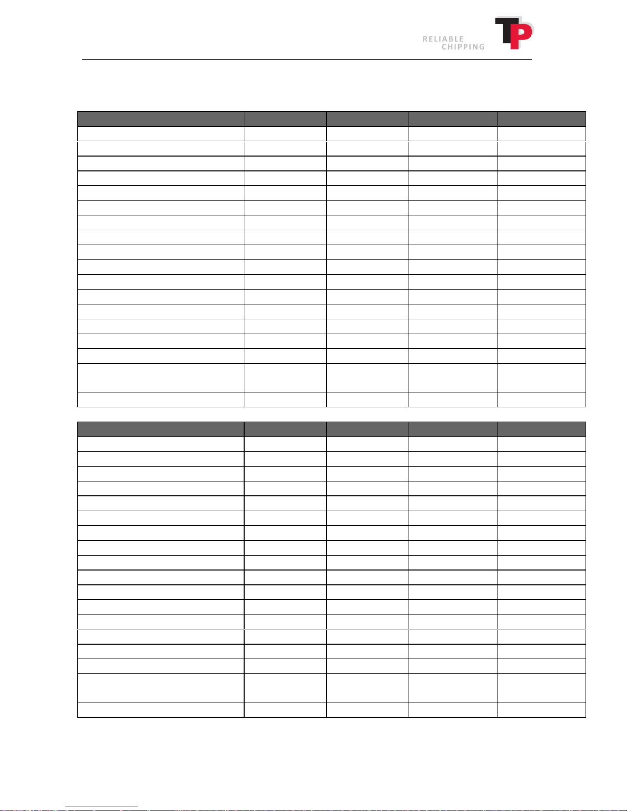
Rotation angle
0° 0°
270°
270°
Disc diameter, mm
835 835 835 835 Disc weight, kg
193 193 193 193
Total number of knives
4 4 4 4
Engine
KDI 1903TCR
KDI 1903TCR
KDI 1903TCR
KDI 1903TCR
Max. wood diameter, mm
235 235 235 235
Chip length, mm
6–16 6–16 6–16 6–16
Tyre fitting
205 R14C
225/75 R16C
195/50 R13C
195/50 R13C
Tyre pressure, bar/PSI
4.5/65
6.5/95
6.5/95
6.5/95
equipment, kg
Type
TP 275 MOBILE
TP 275 MOBILE
TP 275 T MOBILE
TP 275 T MOBILE
Height
-
adjustable drawbar
No
Yes No Yes Chipping principle
Disc chipper
Disc chipper
Disc chipper
Disc chipper
Disc weight, kg
193 193 193 193 rpm disc
1370
1370
1370
1370
Power, kW/(HP)
55/(74)
55/(74)
55/(74)
55/(74)
Chip length, mm
6–16 6–16 6–16 6–16
Tyre pressure, bar/PSI
4.5/65
6.5/95
6.5/95
6.5/95
Permitted total weight, kg
1950
2200
2400
2400
Ó
Copyright 2015
15 Technical data wood chipper
Type TP 235 MOBILE TP 235 MOBILE TP 235 T MOBILE TP 235 T MOBILE
Turntable No No Yes Yes
Height-adjustable drawbar No Yes No Yes
Chipping principle Disc chipper Disc chipper Disc chipper Disc chipper
rpm disc 1160 1160 1160 1160
Power, kW/(HP) 41/(56) 41/(56) 41/(56) 41/(56)
Fuel type Diesel Diesel Diesel Diesel
Knife position, mm 16 16 16 16
Deadweight without extra
1860 2002 2219 2272
Permitted total weight, kg 1950 2200 2400 2400
Turntable No No Yes Yes
Rotation angle 0° 0° 270° 270°
Disc diameter, mm 835 835 835 835
Total number of knives 4 4 4 4
Engine KDI 2504TCR KDI 2504TCR KDI 2504TCR KDI 2504TCR
Fuel type Diesel Diesel Diesel Diesel
Max. wood diameter, mm 275 275 275 275
Knife position, mm 16 16 16 16
Tyre fitting 205 R14C 225/75 R16C 195/50 R13C 195/50 R13C
Deadweight without extra
equipment, kg
We reserve the right to make changes to the design and specifications without notice.
User Manual: TP 235 MOBILE / TP 275 MOBILE from date 01.12.2016 69
1900 2054 2273 2318
Page 70
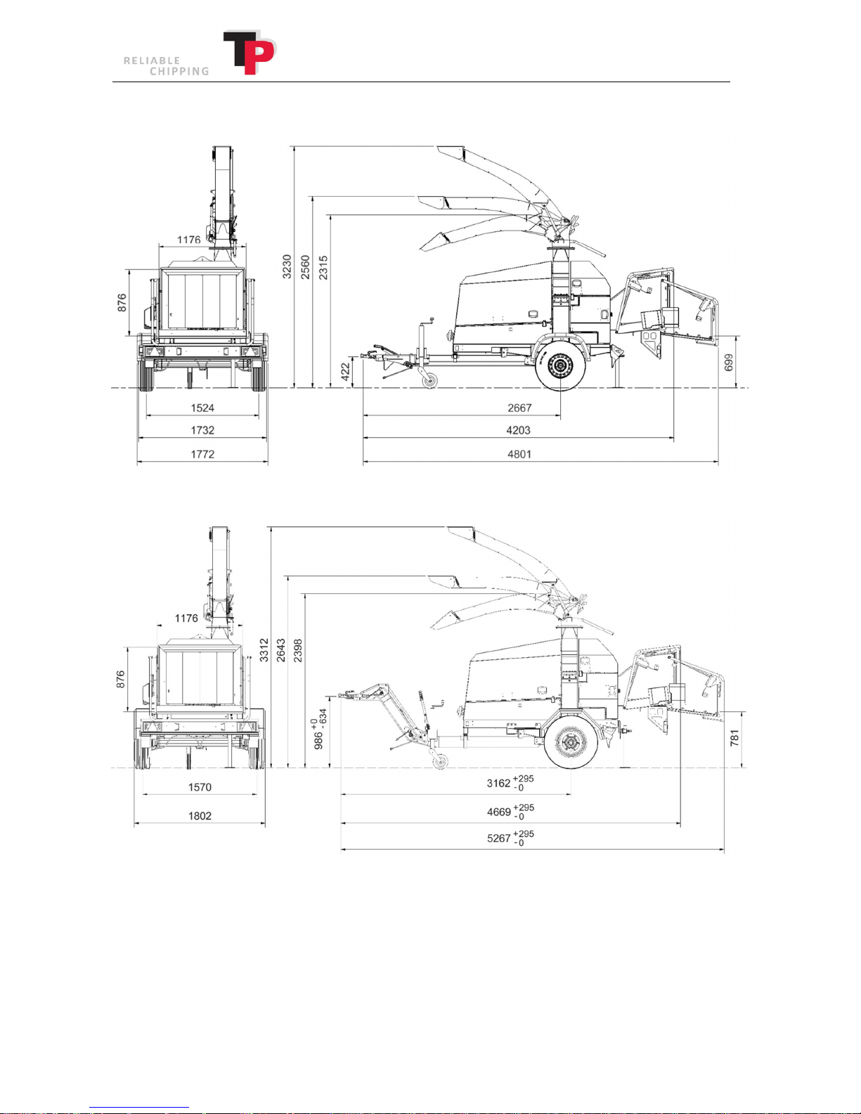
Dimensional drawing for TP 235/275 MOBILE
Ó
Copyright 2015
70 User Manual: TP 235 MOBILE / TP 275 MOBILE from date 01.12.2016
Page 71
Ó
Copyright 2015
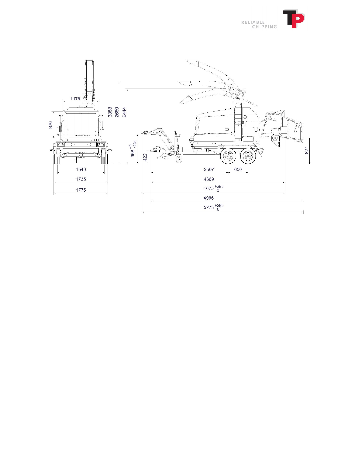
Dimensional drawing for TP 235/275 T MOBILE
User Manual: TP 235 MOBILE / TP 275 MOBILE from date 01.12.2016 71
Page 72
Ó
Copyright 2015
16 Extra equipment
16.1 TP CHIP KIT
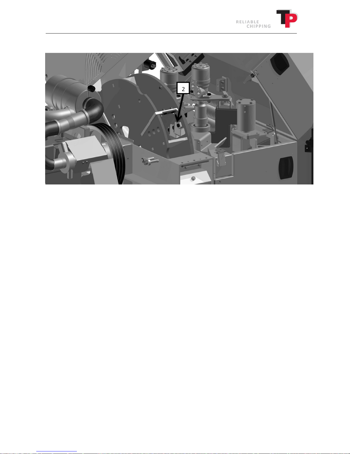
The TP CHIP KIT includes four sliver breakers which are fitted to the knife opening in the disc and a
facing plate, which is fitted to the top in the disc housing.
The TP CHIP KIT provides significantly improved wood chip quality. If woodchip quality is not an
important factor, it will be beneficial if the facing plate and the sliver breakers are removed. This
will increase the capacity of the wood chipper and save fuel.
It is also recommended that the facing plate and the sliver breakers are removed when chipping
wet wood with a lot of needles/leaves. This ensures good ejection.
Replacing the facing plate
1. Open the disc housing as described in chapter 7.
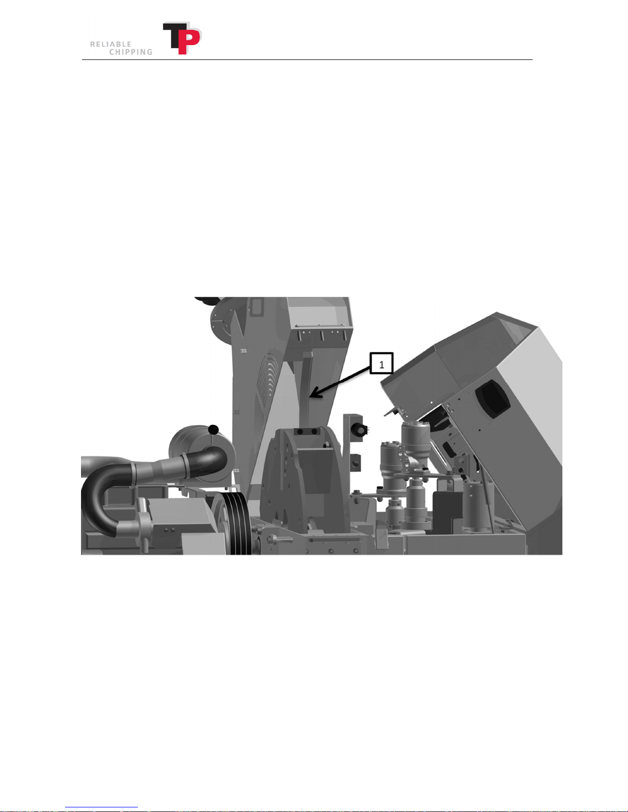
2. Remove the facing plate (1), which is fitted with three bolts in the side of the top disc
housing.
3. Replace the facing plate (1) if it is worn.
4. Fit the new facing plate (1).
5. Finally, close the disc housing as described in chapter 7.
72 User Manual: TP 235 MOBILE / TP 275 MOBILE from date 01.12.2016
Page 73
Ó
Copyright 2015
Replacing the sliver breakers
1. Open the disc housing as described in chapter 7.
2. Remove the bolts that secure the knife and clamping plate/sliver breaker (2) to the disc.
3. Replace the sliver breakers (2).
4. Carefully clean the knife, sliver breaker (2) and contact surface.
5. When fitting the sliver breaker, the bolts must be lightly oiled (m=0.125), i.e. light oil,
WD 40 or an equivalent product. Do not use copper grease, MoS2 or similar low friction
grease.
6. Check that the distance between the knife edge and the counterknife is set correctly to D
(see point 10).
7. Tighten the bolts to 110 Nm / 11 KPm Use a torque spanner for this purpose (available as
extra equipment).
8. Finally, close the disc housing as described in chapter 7.
User Manual: TP 235 MOBILE / TP 275 MOBILE from date 01.12.2016 73
Page 74
16.2 TP TOOLKIT
Ó
Copyright 2015
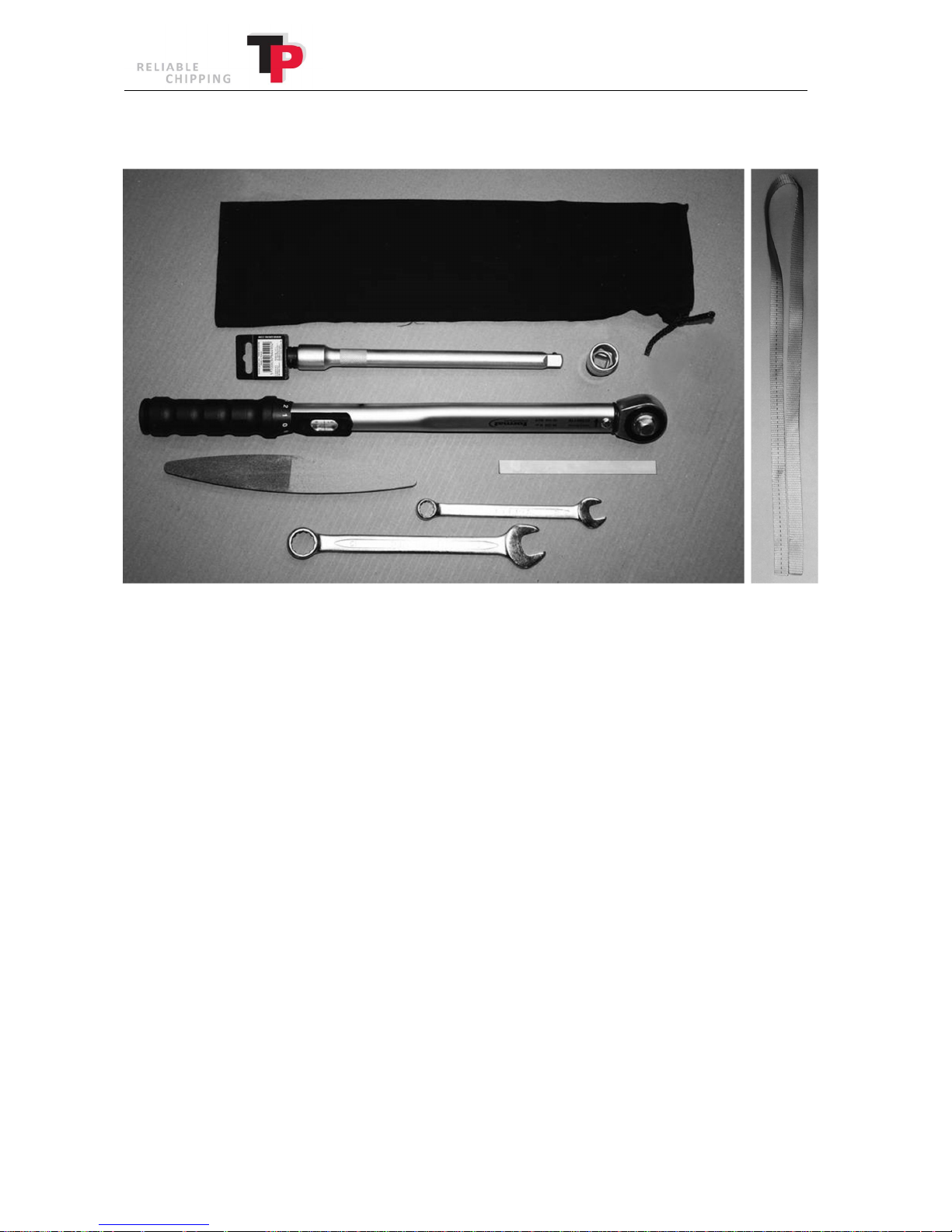
The TP TOOLKIT contains:
· Tool bag
· Combination wrench 13 mm
· Combination wrench 19 mm
· Grinding stone "Flexovit"
· Precision feeler gauge 1.5 x 150 mm
· Torque wrench 5-30 kPm
· WBW-VLL extender 1/2" - 250 mm
· WBM TOP 1/2" - 6 KT/19 mm
· Spring strap
74 User Manual: TP 235 MOBILE / TP 275 MOBILE from date 01.12.2016
Page 75
Ó
Copyright 2015
16.3 TP SPARE WHEEL
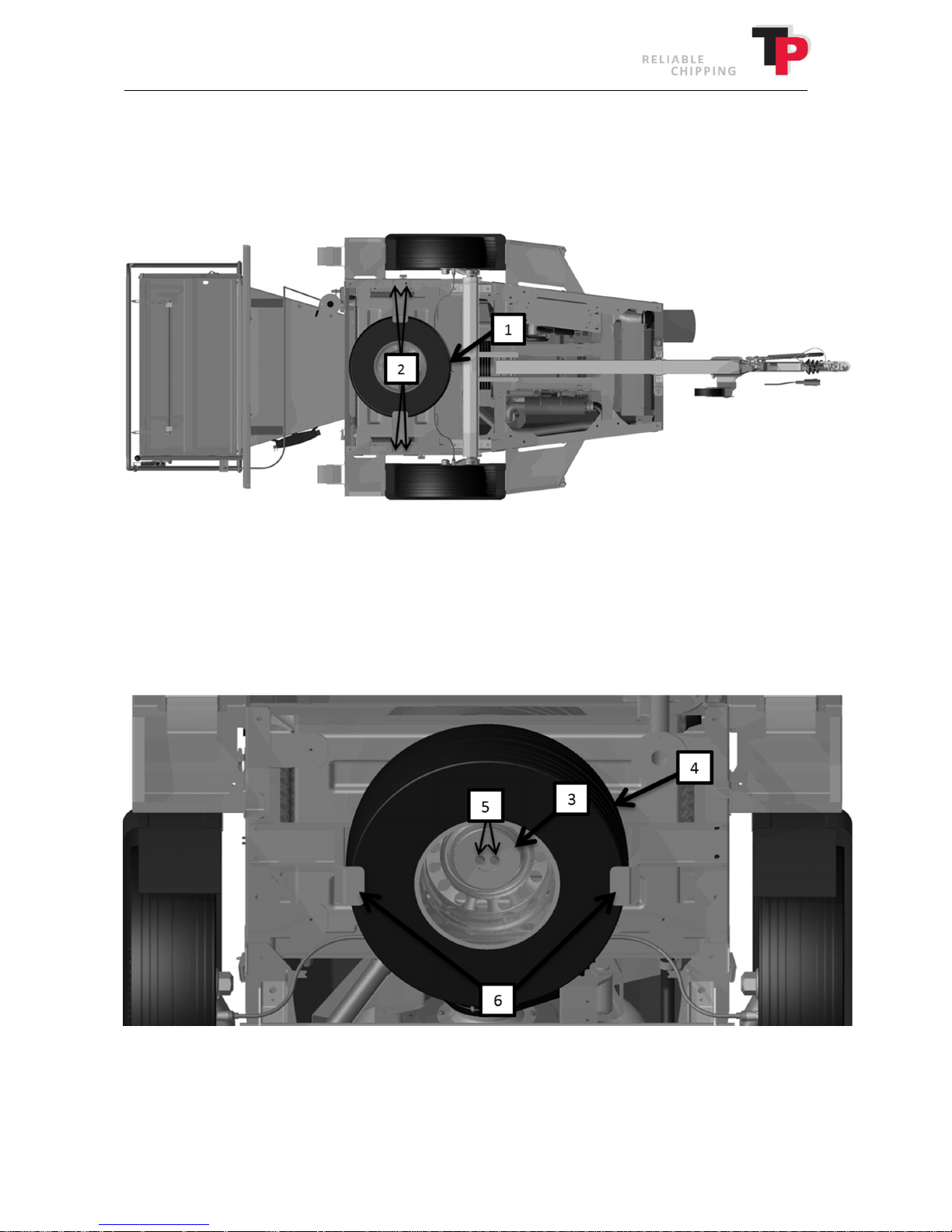
TP SPARE WHEEL contains the spare wheel and fitting for fitting the wheel.
Fitting TP SPARE WHEEL
1. Ensure that the wood chipper is stabilised with the support leg and nose wheel set, so that
it cannot tip over.
2. Fit the TP SPARE WHEEL(1) onto the wood chipper using four bolts (2).
Removing the spare wheel
1. Ensure that the wood chipper is stabilised with the support leg and nose wheel set, so that
it cannot tip over.
2. Remove the wheel holder (3) which holds the wheel (4) by removing the bolts (5). Now
hold the wheel (4) up from the wheel carriage (6).
User Manual: TP 235 MOBILE / TP 275 MOBILE from date 01.12.2016 75
Page 76
Ó
Copyright 2015
3. Pull the wheel (4) out of the wheel carriage (6) so that it lands on the ground. The wheel is
now ready to replace the punctured or damaged wheel on the wood chipper.
Wheel change
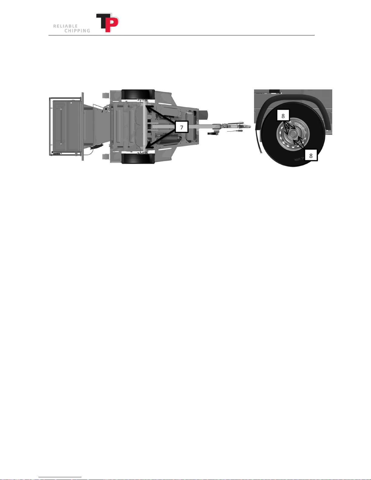
1. Use the jack to lift wood chipper using one of the two lifting points (7) depending on which
wheel is to be replaced. Always put blocks against the wheel until you change the wheel!
2. Remove the wheel bolts (8) that secure the wheel to the wheel axle.
3. Now replace the wheel with the spare wheel and secure the spare wheel using the wheel
bolts (8). Tighten the wheel bolts to 120 Nm.
4. Finally, fit the punctured/damaged wheel inside the spare wheel holder.
76 User Manual: TP 235 MOBILE / TP 275 MOBILE from date 01.12.2016
Page 77
Ó
Copyright 2015
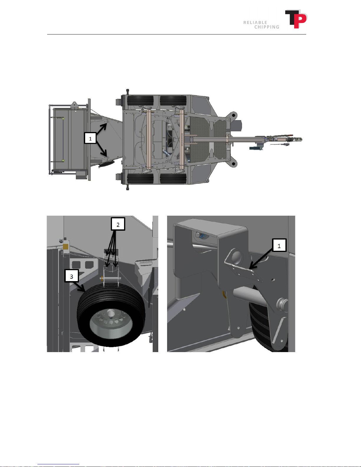
16.4 TP SPARE WHEEL (TP TURNTABLE)
TP SPARE WHEEL contains the spare wheel and fitting for fitting the wheel.
Fitting TP SPARE WHEEL
1. Remove the two hydraulic hose supports (1) below the funnel.
2. Fit the TP SPARE WHEEL(3) onto the underside of the wood chipper using four bolts (2) on
each side.
3. Fit the last two hydraulic hose supports (1) as shown in the image. There must be a support
on each side of the TP SPARE WHEEL(3).
User Manual: TP 235 MOBILE / TP 275 MOBILE from date 01.12.2016 77
Page 78
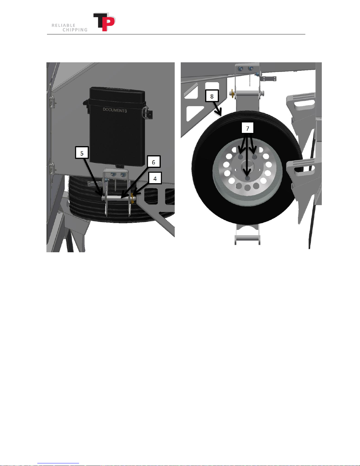
Removing the spare wheel
Ó
Copyright 2015
1. Stand on the left side of the funnel, which faces out to the road.
2. Remove the pin (4) in either end of the shaft (5) in the spare wheel support.
3. Next, pull the shaft (5) while holding the handle (6).
4. Lower the handle (6) by hand as slowly as possible, then let go.
5. Go to the opposite side of the funnel to remove the wheel.
6. Remove the three bolts (7) and pull out the wheel (8). The wheel (8) is now ready to
replace the punctured or damaged wheel on the wood chipper.
78 User Manual: TP 235 MOBILE / TP 275 MOBILE from date 01.12.2016
Page 79
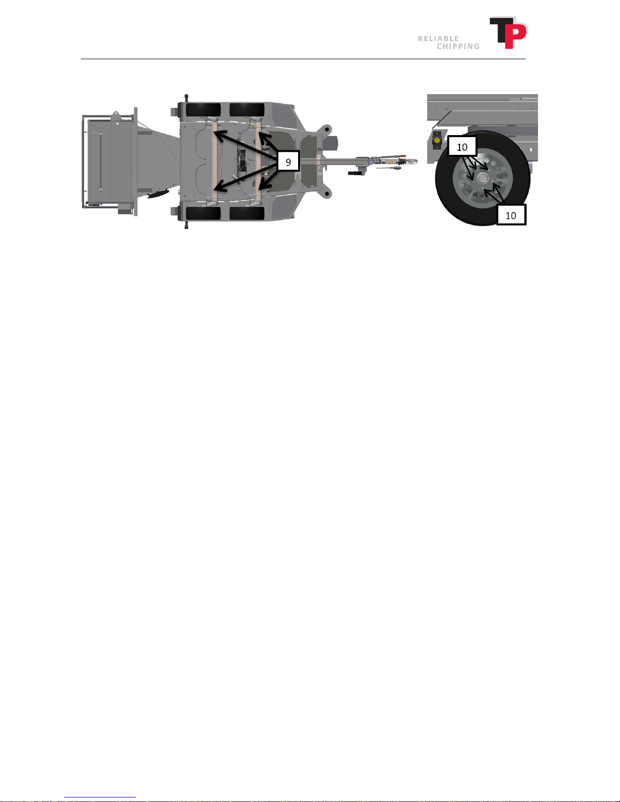
Ó
Copyright 2015
Wheel change
1. Use the jack to lift wood chipper using one of the four lifting points (9) depending on which
wheel is to be replaced. Always put blocks against the wheel until you change the wheel!
2. Remove the wheel bolts (10) that secure the wheel to the wheel axle.
3. Now replace the wheel with the spare wheel and secure the spare wheel using the wheel
bolts (10). Tighten the wheel bolts to 120 Nm.
4. Finally, fit the punctured/damaged wheel inside the spare wheel holder.
User Manual: TP 235 MOBILE / TP 275 MOBILE from date 01.12.2016 79
Page 80

17 Spare Parts Catalogue
80 User Manual: TP 235 MOBILE / TP 275 MOBILE from date 01.12.2016
 Loading...