

Toyotomi MTN A371DV, MTG A371DV Service Manual
Service Manual
Model:
MTN MTG - A371DV

CONTENTS
1. Precaution .................................................................................................................................................... 1
1.1 Safety Precaution ........................................................................................................................ 1
1.2 Warning ....................................................................................................................................... 1
2. Function ........................................................................................................................................................ 5
3. Dimension .................................................................................................................................................... 6
3.1 Indoor Unit ................................................................................................................................... 6
3.2 Outdoor Unit ................................................................................................................................ 7
4. Refrigerant Cycle Diagram ......................................................................................................................... 8
5. Wiring Diagram ............................................................................................................................................ 9
5.1 Indoor Unit ................................................................................................................................... 9
6 Installation Details ....................................................................................................................................... 11
6.1 Wrench torque sheet for installation .......................................................................................... 11
6.2 Connecting the cables ............................................................................................................... 11
6.3 Pipe length and the elevation .................................................................................................... 12
6.4 Installation for the first time........................................................................................................ 13
6.5 Adding the refrigerant after running the system for many years ................................................ 16
6.6 Re-installation while the indoor unit need to be repaired ........................................................... 17
6.7 Re-installation while the outdoor unit need to be repaired ......................................................... 19
7. Operation Characteristics ......................................................................................................................... 21
8. Electronic function .................................................................................................................................... 22
8.1 Abbreviation .............................................................................................................................. 22
8.2 Display function ......................................................................................................................... 22
8.3 Main Protection ......................................................................................................................... 23
8.4 Operation Modes and Functions ............................................................................................... 24
9. Troubleshooting ......................................................................................................................................... 37
9.1 Indoor Unit Error Display ........................................................................................................... 37
9.2 Diagnosis and Solution .............................................................................................................. 38

1
1. Precaution
1.1 Safety Precaution
To prevent injury to the user or other people and property damage, the following
instructions must be followed.
Incorrect operation due to ignoring instruction will cause harm or damage.
Before service the unit, be sure to read this service manual at first.
1.2 Warning
¾ Installation
Do not use a defective or underrated circuit breaker. Use this appliance on a dedicated
circuit.
There is risk of fire or electric shock.
For electrical work, contact the dealer, seller, a qualified electrician, or an authorized
service center.
Do not disassemble or repair the product, there is risk of fire or electric shock.
Always ground the product.
There is risk of fire or electric shock.
Install the panel and the cover of control box securely.
There is risk of fire of electric shock.
Always install a dedicated circuit and breaker.
Improper wiring or installation may cause fore or electric shock.
Use the correctly rated breaker of fuse.
There is risk of fire or electric shock.
Do not modify or extend the power cable.
There is risk of fire or electric shock.
Do not install, remove, or reinstall the unit by yourself (customer).
There is risk of fire, electric shock, explosion, or injury.
Be caution when unpacking and installing the product.
Sharp edges could cause injury, be especially careful of the case edges and the fins on the
condenser and evaporator.

2
For installation, always contact th e dealer or an authorized service center.
Do not install the product on a defective installation stand.
Be sure the installation area does not deteriorate with age.
If the base collapses, the air conditioner could fall with it, causing property damage, product failure,
and personal injury.
Do not let the air conditioner run for a long time when the humidity is very high and a
door or a window is left open.
Take care to ensure that power cable could not be pulled out or damaged during
operation.
There is risk of fire or electric shock.
Do not place anything on the power cable.
There is risk of fire or electric shock.
Do not plug or unplug the power supply plug during operation.
There is risk of fire or electric shock.
Do not touch (operation) the product with wet hands.
Do not place a heater or other appliance near the power cable.
There is risk of fire and electric shock.
Do not allow water to run into electrical parts.
It may cause fire, failure of the product, or electric shock.
Do not store or use flammable gas or combustible near the product.
There is risk of fire or failure of product.
Do not use the product in a tightly closed space for a long time.
Oxygen deficiency could occur.
When flammable gas leaks, turn off the gas and open a window for ventilation before
turn the product on.
If strange sounds or smoke comes from product, turn the breaker off or disconnect the
power supply cable.
There is risk of electric shock or fire.
Stop operation and close the window in storm or hurricane. If possible, remove the
product from the window before the hurricane arrives.
There is risk of property damage, failure of product, or electric shock.

3
Do not open the inlet grill of the product during operation. (Do not touch the electrostatic
filter, if the unit is so equipped.)
There is risk of physical injury, electric shock, or product failure.
When the product is soaked, contact an authorized service center.
There is risk of fire or electric shock.
Be caution that water could not enter the product.
There is risk of fire, electric shock, or product damage.
Ventilate the product from time to time when operating it together with a stove etc.
There is risk of fire or electric shock.
Turn the main power off when cleaning or maintaining the product.
There is risk of electric shock.
When the product is not be used for a long time, disconnect the power supply plug or
turn off the breaker.
There is risk of product damage or failure, or unintended operation.
Take care to ensure that nobody could step on or fall onto the outdoor unit.
This could result in personal injury and product damage.
¾ CAUTION
Always check for gas (refrigerant) leakage after installation or repair of product.
Low refrigerant levels may cause failure of product.
Install the drain hose to ensure that water is drained away properly.
A bad connection may cause water leakage.
Keep level even when installing the product.
It can avoid vibration of water leakage.
Do not install the product where the noise or hot air from the outdoor unit could damage
the neighborhoods.
It may cause a problem for your neighbors.
Use two or more people to lift and transport the product.
Do not install the product where it will be exposed to sea wind (salt spray) directly.
It may cause corrosion on the product. Corrosion, particularly on the condenser and evaporator fins,
could cause product malfunction or inefficient operation.

4
¾ Operational
Do not expose the skin directly to cool air for long time. (Do not sit in the draft).
Do not use the product for special purposes, such as preserving foods, works of art etc.
It is a consumer air conditioner, not a precision refrigerant s ystem.
There is risk of damage or loss of property.
Do not block the inlet or outlet of air flow.
Use a soft cloth to clean. Do not use harsh detergents, solvents, etc.
There is risk of fire, electric shock, or damage to the plastic parts of the product.
Do not touch the metal parts of the product when removing the air filter. They are very
sharp.
Do not step on or put anything on the product. (outdoor units)
Always insert the filter securely. Clean the filter every two weeks or more often if
necessary .
A dirty filter reduces the efficiency of the air conditioner and could cause product malfunction or
damage.
Do not insert hands or other objects through air inlet or outlet while the product is
operated.
Do not drink the water drained from the product.
Use a firm stool or ladder when cleaning or maintaining the product.
Be careful and avoid personal injury.
Replace the all batteries in the remote control with new ones of the same type. Do not
mix old and new batteries or different types of batteries.
There is risk of fire or explosion.
Do not recharge or disassemble the batteries. Do not dispose of batteries in a fire.
They may burn of explode.
If the liquid from the batteries gets onto your skin or clothes, wash it well with clean
water. Do not use the remote of the batteries have leaked.
5
2. Function
Model Names of Indoor/Outdoor Units
DC
Inverter
Capacity Indoor units Outdoor units
24k MTN A371DV MTG A371DV
Filter
Ionizer(O)
Silver Ico Filter(O)
Vitamin C Filter(O)
3M HAM Filter(O)
Bio Filter(O)
Golden Fin(O)
killer of formaldehyde
Compressor Crankcase Heater(O)
Self Clean
Follow me
8 degree heating(O)
Heat compensation(O)
Self-diag. function
Hydrophilic aluminum fin
Anti-rust cabinet
Valve protection cover
PTC Heating Belt(O)
O: optional function
6
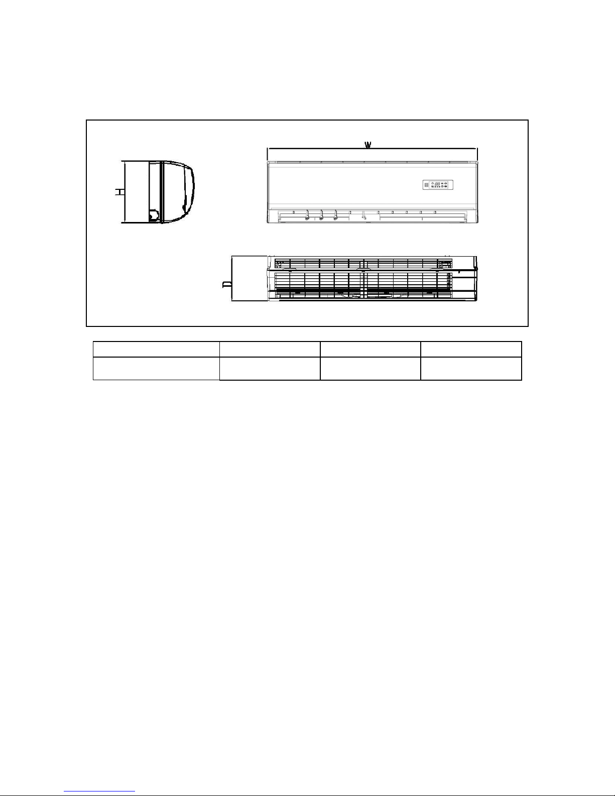
3. Dimension
3.1 Indoor Unit
Model W D H
MTN A371DV 998 235 322
7
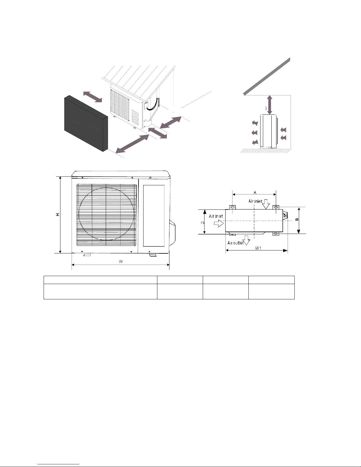
3.2 Outdoor Unit
More than 30cm
More than 60cm
More than 70cm
More than 30cm
More than 60cm
(Service space
︶
F
e
n
c
e
o
r
o
b
s
t
a
c
l
e
s
Model W D H
MTG A371DV 900 315 860

8
4. Refrigerant Cycle Diagram
INDOO
R
OUTDOOR
LIQUID SIDE
GAS SIDE
HEAT
EXCHANGE
(EVAPORATOR)
HEAT
EXCHANGE
(CONDENSER)
COMPRESSOR
2-WAY VALVE
3-WAY VALVE
CHECK VALVE
(Heating Model only)
CAPILIARY TUBE
REVERSING VALVE
(Heating Model only)
COOLING
HEATING
ACCUMULATOR
9
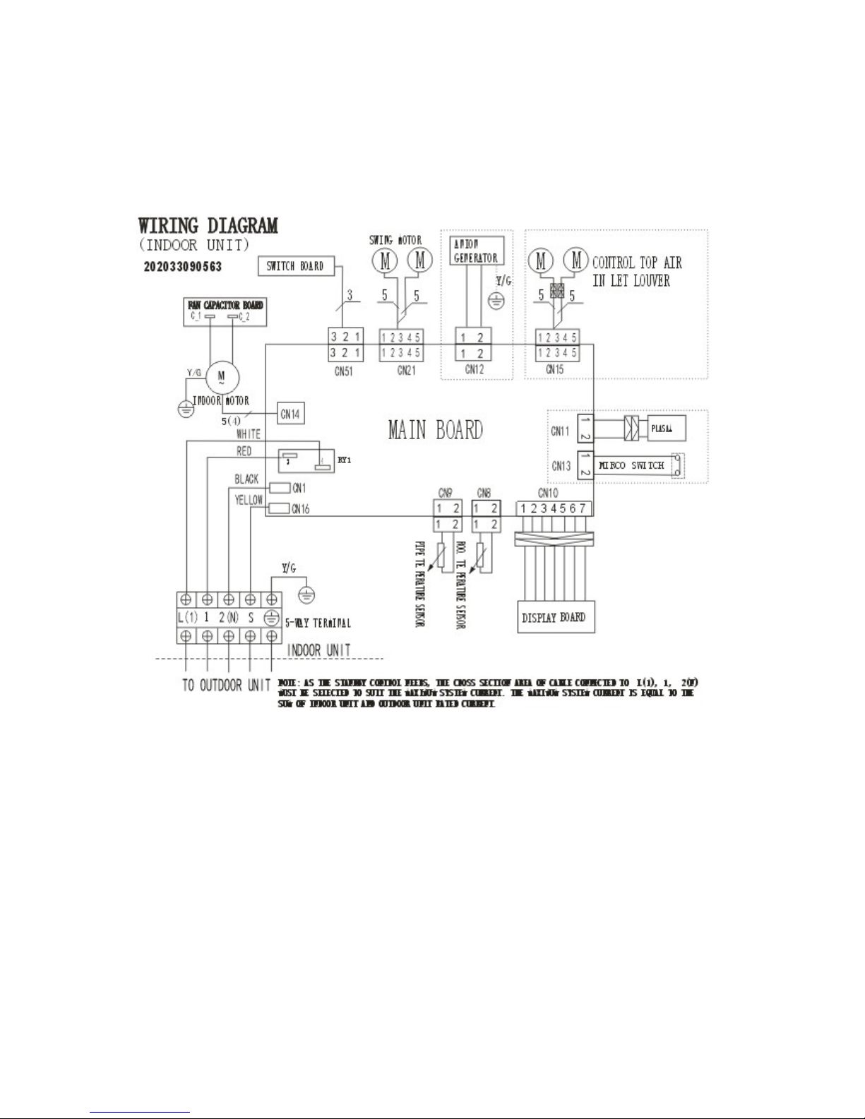
5. Wiring Diagram
5.1 Indoor Unit
MTN-A371DV

10
5.2 Outdoor Unit
MTG A371DV
1
2
3
U(R)
W(C)
4
-
W
A
Y
OUTDOOR
FAN
BLUE
BROWN
BLUE
YELLOW
Y/G
U
V
W
RY3
4
CN6
CN7
CN5
CN4
C
N
1
0
N
-
B
1
2
3
RED
YELLOW
ORANGE
RED
YELLOW
ORANGE
C
N
3
C
N
2
C
N
1
CN15
CN14
CN16
Ct1
N-A
YELLOW
ORANGE
OUTDOOR
MAI
N
PCB
COMPRESSOR
Y/G
R
E
D
B
L
U
E
B
L
A
C
K
W
H
I
T
E
B
L
A
C
K
CAPACITOR
HEATER 1
OPTI ONAL: HEATER
HEATER 2
5
Y/G
B
L
U
E
CN31
CN33
CN32
CN34
W
H
I
T
E
W
H
I
T
E
1
2
3
B
L
U
E
TO INDOOR UNIT
POWER SUPPLY
R
E
D
B
L
U
E
R
E
D
B
L
A
C
K
BLUE
BLUE
11
6 Installation Details
6.1 Wrench torque sheet for installation
Outside diameter Torque Additional tightening torque
mm inch N.cm N.cm
Ф6.35 1/4 1500(153kgf.cm) 1600(163kgf.cm)
Ф9.52 3/8 2500(255kgf.cm) 2600(265kgf.cm)
Ф12.7 1/2 3500(357kgf.cm) 3600(367kgf.cm)
Ф16 5/8 4500(459kgf.cm) 4700(479kgf.cm)
Ф19 3/4 6500(663kgf.cm) 6700(683kgf.cm)
6.2 Connecting the cables
The power cord of connect should be selected according to the following specifications sheet.
Rated current of appliance Nominal cross-sectional area (mm²)
>3 and ≤6 0.75
>6 and ≤10 1
>10 and ≤16 1.5
>16 and ≤25 2.5
The cable size and the current of the fuse or switch are determined by the maximum current indicated
on the nameplate which located on the side panel of the unit. Please refer to the nameplate before
selecting the cable, fuse and switch.

12
6.3 Pipe length and the elevation
The pipe length and refrigerant amount:
Capacity
Btu/h
Pipe size
Standard
length
(m)
Max.
Elevation
B (m)
Max.
Length
A (m)
Additional
refrigerant
(g/m)
Gas Liquid
MTN A371DV + MTG A371DV
5/8’’
(Ф16)
3/8’’
(Ф9.53)
5 10 25 40
Caution:
The capacity test is based on the standard length and the maximum permissive length is based on the
system reliability.
The oil trap should be installed per 5-7 meters.
 Loading...