

Toyotomi Kuro MTN A228DV, MTN A235DV, MTG A228DV, MTG A235DV Service Manual

SERVICE MANUAL
DC INVERTER
SPLIT WALL-MOUNTED TYPE
AIR CONDITIONER
MTN/MTG A228DV
MTN/MTG A235DV
V1.0 2009

CONTENTS
1. Precaution ................................................................................................................................................. 1
1.1 Safety Precaution ................................................................................................................................................ 1
1.2 Warning ............................................................................................................................................................... 1
2. Function .................................................................................................................................................... 3
3. Dimension ................................................................................................................................................. 5
3.1 Indoor Unit ........................................................................................................................................................... 5
3.2 Outdoor Unit ........................................................................................................................................................ 6
4. Specification ............................................................................................................................................. 7
5. Refrigerant cycle diagram ....................................................................................................................... 8
6. Wiring diagram ......................................................................................................................................... 9
6.1 Indoor Unit ........................................................................................................................................................... 9
6.2 Outdoor Unit ........................................................................................................................................................ 9
7. Installation details .................................................................................................................................. 10
7.1 Wrench torque sheet for installation .................................................................................................................. 11
7.2 Connecting the cables ....................................................................................................................................... 11
7.3 Pipe length and the elevation ............................................................................................................................ 11
7.4 Air purging of the piping and indoor unit ............................................................................................................ 11
7.5 Pumping down (Re-installation) ......................................................................................................................... 13
7.6 Re-air purging (Re-installation) ................................................................ .......................................................... 14
7.7 Balance refrigerant of the 2-way, 3-way valves ................................................................................................. 15
7.8 Evacuation ......................................................................................................................................................... 16
7.9 Gas charging ..................................................................................................................................................... 17
8. Operation characteristics ...................................................................................................................... 18
8.1 MTN/MTG A228DV ............................................................................................................................................ 18
8.2 MTN/MTG A235DV ............................................................................................................................................ 19
9. Electronic function ................................................................................................................................. 20
9.1 Abbreviation....................................................................................................................................................... 20
9.2 Display function ................................................................................................................................................. 20
9.3 Protection .......................................................................................................................................................... 20
9.4 Fan-Only Mode .................................................................................................................................................. 21
9.5 Cooling Mode .................................................................................................................................................... 22
9.6 Drying mode ...................................................................................................................................................... 23
9.7 Heating mode .................................................................................................................................................... 23
9.8 Auto mode function ............................................................................................................................................ 27
9.9 Forced operation function .................................................................................................................................. 27
9.10 Action of 4-way valve ....................................................................................................................................... 27
9.11 Two speeds outdoor fan function ..................................................................................................................... 27
9.12 Timer function .................................................................................................................................................. 28
9.13 Sleep function mode ........................................................................................................................................ 28
9.14 Auto-Restart function ....................................................................................................................................... 28
9.15 Ionizer/Plasma dust collector function(optional) .............................................................................................. 29
9.16 Outdoor chassis heating cable ....................................................................................................................... 29
10. Troubleshooting ................................................................................................................................... 30
10.1 Indoor Unit Error Display ................................................................................................................................. 31

10.2 Diagnosis and Solution .................................................................................................................................... 32
10.3 Key parts checking. ......................................................................................................................................... 35

1
1. Precaution
1.1 Safety Precaution
To prevent injury to the user or other
people and property damage, the following instructions
must be followed.
Incorrect operation due to ignoring
instruction will cause harm or damage.
Before service unit, be sure to read
this service manual at first.
1.2 Warning
Installation
Do not use a defective or underrated
circuit breaker. Use this appliance on a dedicated
circuit.
There is risk of fire or electric shock.
For electrical work, contact the dealer,
seller, a qualified electrician, or an Authorized service
center.
Do not disassemble or repair the product, there is risk of
fire or electric shock.
Always ground the product.
There is risk of fire or electric shock.
Install the panel and the cover of
control box securely.
There is risk of fire of electric shock.
Always install a dedicated circuit and
breaker.
Improper wiring or installation may cause fore or electric
shock.
Use the correctly rated breaker of
fuse.
There is risk of fire or electric shock.
Do not modify or extend the power
cable.
There is risk of fire or electric shock.
Do not install, remove, or reinstall the
unit by yourself(customer).
There is risk of fire, electric shock, explosion, or injury.
Be caution when unpacking and
installing the product.
Sharp edges could cause injury, be especially careful of the
case edges and the fins on the condenser and evaporator.
For installation, always contact the
dealer or an Authorized service center.
There is risk of fire, electric shock, explosion, or injury.
Do not install the product on a
defective installation stand.
It may cause injury, accident, or damage to the product.
Be sure the installation area does not
deteriorate with age.
If the base collapses, the air conditioner could fall with it,
causing property damage, product failure, and personal
injury.
Do not let the air conditioner run for a
long time when the humidity is very high and a door or
a window is left open.
Moisture may condense and wet or damage furniture.
Take care to ensure that power cable
could not be pulled out or damaged during operation.
There is risk of fire or electric shock.
Do not place anything on the power
cable.
There is risk of fire or electric shock.
Do not plug or unplug the power
supply plug during operation.
There is risk of fire or electric shock.
Do not touch (operation) the product
with wet hands.
There is risk of fire or electric shock.
Do not place a heater or other
appliance near the power cable.
There is risk of fire and electric shock.
Do not allow water to run into electric
parts.
It may cause fire, failure of the product, or electric shock.
Do not store or use flammable gas or
combustible near the product.
There is risk of fire or failure of product.
Do not use the product in a tightly
closed space for a long time.
Oxygen deficiency could occur.
When flammable gas leaks, turn off
the gas and open a window for ventilation before turn
the product on.
Do not use the telephone or turn switches on or off.
There is risk of explosion or fire.
If strange sounds, or small or smoke
comes from product. Turn the breaker off or disconnect
the power supply cable.
There is risk of electric shock or fire.
Stop operation and close the window
in storm or hurricane. If possible, remove the product
from the window before the hurricane arrives.
There is risk of property damage, failure of product, or

2
electric shock.
Do not open the inlet grill of the
product during operation. (Do not touch the
electrostatic filter, if the unit is so equipped.)
There is risk of physical injury, electric shock, or product
failure.
When the product is soaked (flooded
or submerged), contact an Authorized service center.
There is risk of fire or electric shock.
Be caution that water could not enter
the product.
There is risk of fire, electric shock, or product damage.
Ventilate the product from time to time
when operating it together with a stove, etc.
There is risk of fire or electric shock.
Turn the main power off when cleaning
or maintaining the product.
There is risk of electric shock.
When the product is not be used for a
long time, disconnect the power supply plug or turn off
the breaker.
There is risk of product damage or failure, or unintended
operation.
Take care to ensure that nobody could
step on or fall onto the outdoor unit.
This could result in personal injury and product damage.
CAUTION
Always check for gas (refrigerant)
leakage after installation or repair of product.
Low refrigerant levels may cause failure of product.
Install the drain hose to ensure that
water is drained away properly.
A bad connection may cause water leakage.
Keep level even when installing the
product.
To avoid vibration of water leakage.
Do not install the product where the
noise or hot air from the outdoor unit could damage the
neighborhoods.
It may cause a problem for your neighbors.
Use two or more people to lift and
transport the product.
Avoid personal injury.
Do not install the product where it will
be exposed to sea wind (salt spray) directly.
It may cause corrosion on the product. Corrosion,
particularly on the condenser and evaporator fins, could
cause product malfunction or inefficient operation.
Operational
Do not expose the skin directly to cool
air for long periods of time. (Do not sit in the draft).
This could harm to your health.
Do not use the product for special
purposes, such as preserving foods, works of art, etc.
It is a consumer air conditioner, not a precision
refrigerant system.
There is risk of damage or loss of property.
Do not block the inlet or outlet of air
flow.
It may cause product failure.
Use a soft cloth to clean. Do not use
harsh detergents, solvents, etc.
There is risk of fire, electric shock, or damage to the plastic
parts of the product.
Do not touch the metal parts of the
product when removing the air filter. They are very
sharp.
There is risk of personal injury.
Do not step on pr put anything on the
product. (outdoor units)
There is risk of personal injury and failure of product.
Always insert the filter securely. Clean
the filter every two weeks or more often if necessary.
A dirty filter reduces the efficiency of the air conditioner and
could cause product malfunction or damage.
Do not insert hands or other object
through air inlet or outlet while the product is operated.
There are sharp and moving parts that could cause
personal injury.
Do not drink the water drained from
the product.
It is not sanitary could cause serious health issues.
Use a firm stool or ladder when
cleaning or maintaining the product.
Be careful and avoid personal injury.
Replace the all batteries in the remote
control with new ones of the same type. Do not mix old
and mew batteries or different types of batteries.
There is risk of fire or explosion.
Do not recharge or disassemble the
batteries. Do not dispose of batteries in a fire.
They may burn of explode.
If the liquid from the batteries gets
onto your skin or clothes, wash it well with clean water.
Do not use the remote of the batteries have leaked.
The chemical in batteries could cause burns or
other health hazards
3
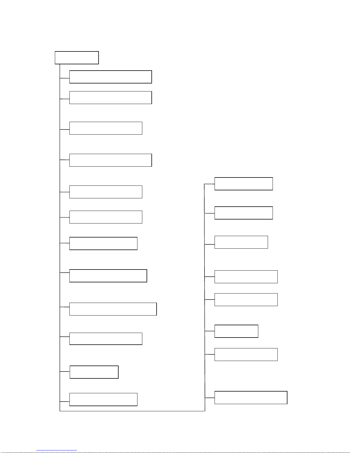
2. Function
When the power supply is
interrupted and then restore, the air
conditioners automatically restore
the previous function setting.
BLDC fan motor
Maintain the room temperature in accordance w
ith the setting temperature.
The mode can be change by the room temperature.
The louver can be set at the desired position or
swing up and down automatically
The function is usually used in rainy days in
springtime or damp areas.
The fan is turn to low speed (cooling/heating).
The unit will be turn off at the seventh hour.
The unit will decide the louver direction according to
operation mode.
Turbo wind, high, med, low, breeze.
Restarting is for approx. 3 minutes..
Prevent the water being frozen on evaporator by sensing
the evaporator pipe temperature in cooling mode
Room temperature sensor.
Pipe temperature sensor.
Indoor unit
Operation by remote controller
Sensing by room temperature
Room temperature control
Anti-freezing control in cooling
Time Delay Safety control
Indoor fan speed control
Two-direction air vane
Sleep mode auto control
Independent dehumidification
Air flow Direction control
Auto mode
Temp. Compensation
Flexible wiring connection
Auto defrost
Plasma (Optional)
Anti-cold function
Self-diag. function
Auto-restart function
Prevent the cold wind at the
beginning of unit start.
4
It protects the valves and prevents water from dripping.
The unit has 3 mins delay between continuously ON/OFF operations.
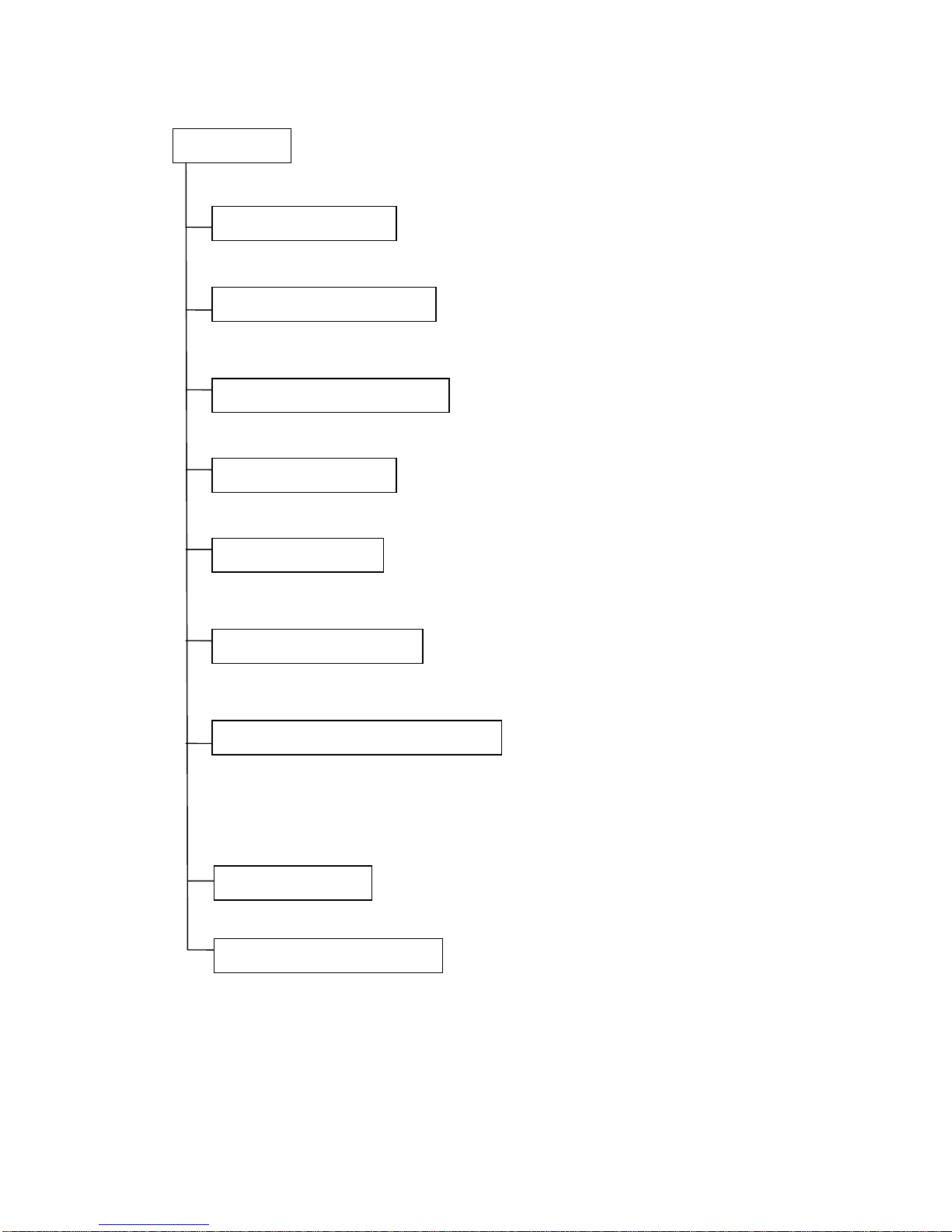
Outdoor unit
Power relay control
The hydrophilic fin can improve the heating efficiency at operation mode.
Hydrophilic aluminum fin
It is only operated in the heating operation mode except defrosting operation.
Anti-rust cabinet
Valve protection cover
4 way valve control
Made from electrolytic zinc steel sheet and anti-rust coated components.
Low noise air flow system
Bird tail propeller fan makes the outdoor unit run more quietly.
Discharge pipe temperature protect
Driving heating at -15℃

5
3. Dimension
3.1 Indoor Unit
MTN A228DV MTN A235DV
Dimension
Mode
W H L
9K 790 213 252
12K 790 213 252
W L H

6
3.2 Outdoor Unit
MTG A228 DV MTG A235 DV

7
4. Specification
Sale model MTN/MTG A228DV MTN/MTG A235DV
V-Ph-Hz
1Ph, 220-240V~, 50Hz 1Ph, 220-240V~, 50Hz
Capacity Btu/h 9000(3100~11200) 12000(3800~14700)
Power consumption W 660(300~1100) 970(400~1480)
Operating current A 2.9(1.3~4.8) 4.3(1.8~6.5)
EER W/W 4.01 3.61
Capacity Btu/h 10000(3300~12300) 13000(4000~15200)
Power consumption W 690(310~1150) 950(390~1460)
Operating current A 3.0(1.4~5.0) 4.2(1.7~6.4)
COP W/W 4.21 4.01
W 1500 1600
A 8.0 8.5
A 8.0 8.0
g R410A/1100g R410A/1100g
MPa 4.2/1.5 4.2/1.5
Air flow (High/Mid/Low) m3/h 550/400/280 580/400/280
Noise level (High/Mid/Low) dB(A) 36/31/35 38/33/27
Air flow (High/Mid/Low) m3/h 1800/-/1400 1800/-/1400
Noise level (High/Mid/Low) dB(A) 53 54
Operation temp
℃
17-30 17-30
Ambient temp(Cooling/Heating)
℃
18-50/-15-34 18-50/-15-34
Application area m2 13-22 18-29
Dimension (W*D*H) mm 790x213x252 790x213x252
Packing (W*D*H) mm 863x273x323 863x273x323
Net/Gross weight Kg 8.5/10.5 8.5/10.5
Dimension (W*D*H) mm 760x285x590 760x285x590
Packing (W*D*H) mm 887x355x645 887x355x645
Net/Gross weight Kg 40.5/43 40.5/43
Model DA108X1C-20FZ3 DA108X1C-20FZ3
Type ROTARY ROTARY
Brand TOSHIBA TOSHIBA
Capacity Btu/h 10918 ±5% 10918 ±5%
Input W 855±5% 855±5%
Rated current(RLA) A 5.30±5% 5.30±5%
Locked rotor Amp(LRA) A 10 10
Thermal protector position EXTERNAL EXTERNAL
Capacitor μF 45μF/450V 45μF/450V
Refrigerant oil/oil charge ml ESTER OIL VG74 / 480 ESTER OIL VG74 / 480
Model RPG20N RPG20N
Brand Welling Welling
Input W 45±10% 45±10%
Capacitor μF 1.5μF/450V 1.5μF/450V
Speed(High/Mid/Low) r/min 1300/1050/850 1300/1050/850
Model YDK24-6G YDK24-6G
Brand Welling Welling
Input W 67±10%/48±10% 67±10%/48±10%
Capacitor μF 2.5μF/450V 2.5μF/450V
Speed(High/Mid/Low) r/min 800/550 800/550
Liquid side/ Gas side mm(inch) φ6.35/φ9.53(1/4"/3/8") φ6.35 / φ12.7(1/4"/1/2")
Max. refrigerant pipe length m 10 10
Max. difference in level m 5 5
Outdoor
Power supply
Cooling
Heating
Max. input consumption
Max. current
Starting current
Refrigerant type
Design pressure
Indoor
Outdoor fan motor
Refrigerant piping
Applicable Ambient
Indoor unit
Outdoor unit
Compressor
Indoor fan motor
The above design and specifications are subject to change without prior notice for product improvement.
8
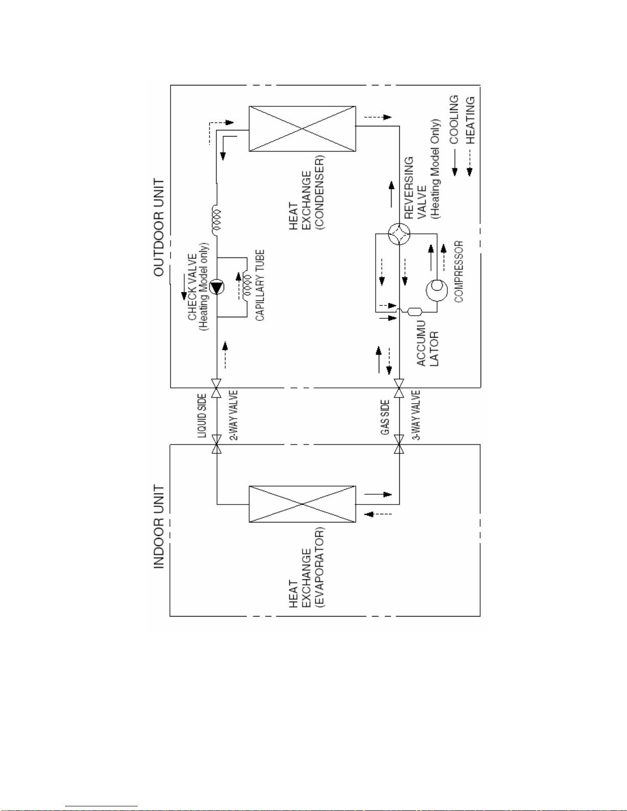
5. Refrigerant cycle diagram

9
6. Wiring diagram
6.1 Indoor Unit
MTN A228DV MTN A235DV
NOTES:
1. The Color Of Power Supply Cord(L N E) Measur es Up To The I EC St andards BROWN
BI UE Y/ G Or The UL St anda rds BLACK WHITE GREEN ;
2. The Functi ons I n The Rectangle Are Avail able For Par ti cu lar Ai r-conditi on;
、、 ( 、
、 ) ( 、 、 )
CN1
RED
BLUE(OR WHI TE)
BLACK
TO OUTDOOR UNIT
LSN
YELLOW
TERMINAL
MAIN BOARD
( I NDOOR UNI T)
CN9
EVAPORATOR SENSOR
2
1
2
1
CN11
AMBIENT SENSOR
21
2
1
CN7
MI RCO SWI TCH
2
1
1 2 3 4 5
SWI NG MOTOR
M
5
1 2 3 4 5
CN5
This symbol indicates the element
is optional,the actual shape shall
be prevail.
Notes:
DISPLAY
CN10
BOARD
REC
BOARD
1 2 3 4 5 6 7 8 9 10
CN3
PLASMA
1234
INDOOR UNIT
Y/G
CN6
CN2
CN8
INDOOR MOTOR
3 2 1
3 2 1
M
1 3 5
1 3 5
RY1
3
4
BROWN(OR BLACK)
Y/G(OR GREEN)
POWER SUPPLY
OPTIONAL
202032390830
 Loading...