

Page 1
Page 2
Page 3
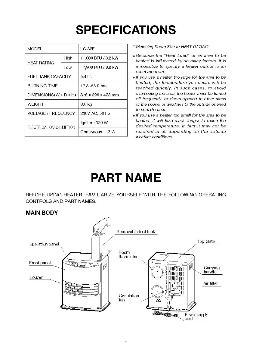
OPERATION PANEL
Timer Key
Key-lock Button
Digital Indicator
Adjustment Keys
ON/OFF Lamp —flashing : Preheating mode
constant : Heater in operation
key-lock Indicator —constant : Childproof Lock is on.
Temperature Indicator —constant : The Digital Indicator shows Set
temperature and Room temperature.
Clock Indicator —constant : The Digital Indicator shows current time.
Timer Lamp —constant : Heater in operation in timer mode.
Ventilation Indicator —flashing : Oxygen level in room is insufficient. Heater
shuts off automatically.
Fuel Indicator —constant : Fuel tank empty. Only 10 minutes burning
time remaining. Digital indicator shows the
remaining burning time in minutes.
You can hear the alarm every 2 minutes.
ON/OFF
Button/Lamp
flashing : Heater extinguished due to lack of fuel. (10
seconds alarm)
2
Page 4
UNPACKING AND PLACEMENT
1. Take out heater from box carefully to avoid damage.
2. Remove all packing materials from heater.
3. Make sure all screws are tight and all parts intact.
NOTE:Save shipping carton and all packing materials for future storage of your heater.
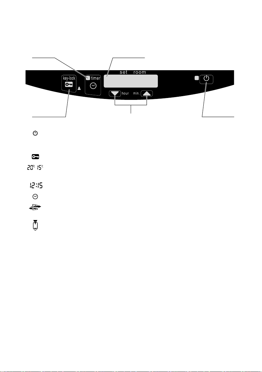
4. When positioning your heater for use, keep it away from walls and all other materials as
illustrated below.
150 cm
20 cm
50 cm
50 cm
150 cm
5. The floor should be firm and completely level. Reposition the heater, when it is not level.
NOTE:If your heater is not on a level surface, change its location. Do not attempt to prop
heater up with books or other objects.
3
Page 5
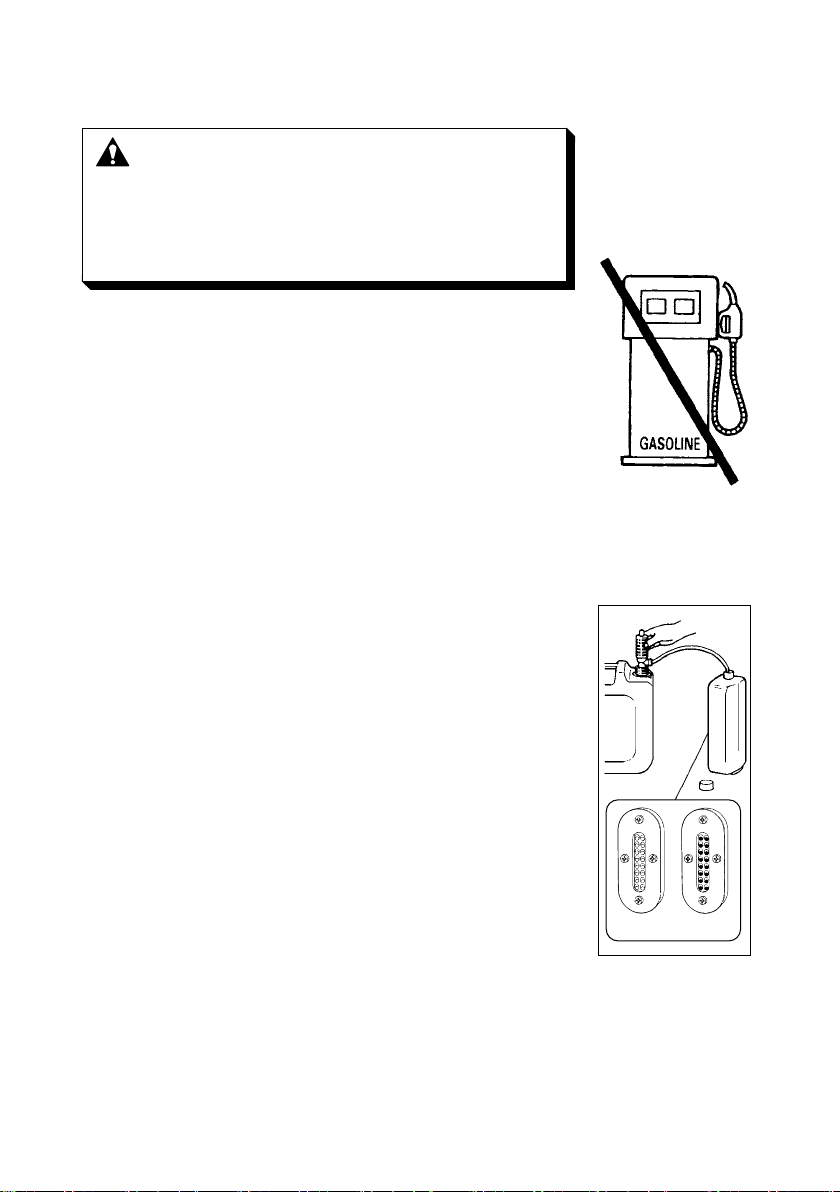
FUELING
WARNING :
1. Open the fuel tank lid on the top of heater cabinet and lift out the
removable fuel tank. Turn the removable tank upside down and
remove the fuel tank cap.
2. Insert the straight tube of the manual siphon into the jerrycans;
insert the siphon’s flexible hose into the removable fuel tank
opening.
3. Turn the air vent knob on the top of the siphon clockwise to
close the vent. Start the flow of kerosene (paraffin) by squeezing
the bulb of the siphon vigorously six or seven times. Once flow
begins, it is no longer necessary to squeeze the bulb.
4. Check the removable tank fuel gauge while filling the tank. Stop
filling by loosening the switch button on top of the pump (turn
anti-clockwise), once the gauge indicates that the tank is full.
Never overfill the tank, especially not when the fuel is very cold
(fuel expands when it heats up).
Use only water-clear kerosene (paraffin).
Never use gasoline or other flammable
liquids.
ALWAYS extinguish heater before refill
heater fuel tank.
Fuel heater outside the living area.
NOTE:Be careful to avoid overfilling the tank, especially with
very cold kerosene (paraffin). Overflow might occur due
to expansion when the fuel warms up.
5. Remove the siphon carefully, allowing excess kerosene (paraffin)
to drain from the tube back into the jerrycans. Replace fuel tank
cap and tighten it securely. Be sure to wipe away any spilled
kerosene (paraffin) from tank and other heater parts.
6. After making sure fuel tank cap is tightly fastened, invert tank
and replace into heater body.
4
empty full
Page 6

OPERATION
CAUTION :Always make sure that there is sufficient ventilation.
SET CLOCK
It is only possible to set the correct time, when the heater is
connected to the mains and not burning.
1. Use the Adjustment Keys (▼ hour /▲ min.) to set the time.
2. To set the time, press “hour” and “min.” set
buttons. Individual motions will increase the
time by one unit; holding continuously will
raise either the “hour” or “min.” rapidly. After
approximately 10 seconds the blinking will
stop and the setting will be locked. 5 Minutes
after switching off the heater, the information
on the display will disappear and the heater will automatically switch into the stand-by
position.
IGNITION
21
1. Just press the button to ignite the heater. The button will start blinking, indicating
that the ignition procedure has started. This will take a short while.
2. After this time heater will automatically ignite and The button will cease its flashing. The
Operation Lamp will remain alight so long as heater is burning.
NOTE:If using your heater for the first time, or after long term storage, ignition may not
take place on the first try. Press the button again.
NOTE:Fuel pump may produce an audible operating noise at ignition. This is only
temporary.
5
Page 7

TIMER IGNITION
Your heater can be arranged to ignite automatcally at a chosen time by use of a pre-set
“Timer”. This “Timer” can only be set after the clock setting has been completed.
1
2
1. Press the button and then the “Timer” key immediately after
that. The Timer Lamp and Digital Indicator will start blinking.
3 4
2. To set the
the same procedure as given earlier for “Clock” time setting.
After approximately 10 seconds, the digital indicator will return to
“Clock” mode, displaying the present time.
3. Your heater will now automatically start up the pre-set time.
4. If you wish to start up the heater at the pre-set time again, repeat the same procedure 1.
mentioned above.
NOTE:The pre-set time will remain so long as the heater receives electrical power. In the
NOTE:If normal ignition was used to set the heater burning (i.e. the heater is burning but
“
Timer” to the chosen igntion time, you should follow
event of power failure or disconnection of heater for more than 10 minutes, timer
setting will be cancelled.
the Timer Lamp on the Indicator panel is out), pressing the Timer key will
extinguish the heater, and the heater will be put into the “Timer”mode.
6
Page 8

TEMPERATURE REGULATION
1. Use the Adjustment keys (▼ hour / ▲ min.) to adjust the
temperature.
2. Adjust the temperature using the key on the right ( ▲ min.) to set
the temperature to a higher setting and the key on the left
(▼ hour ) to lower the temperature.
3. Until the room temperature has reached the set temperature, the heater will burn at either
high or medium burning mode. When the room temperature reaches or slightly exceeds
the set temperature, the heater will automatically shift to maintain the desired
temperature.
NOTE:The standard setting of the heater is 20°C. However, once the set temperature has
been changed the new setting will remain in effect unless changed.
NOTE:Room temperature measurements are taken directly behind the heater. These
measurements may not represent the true room temperature.
1 2
7
Page 9

CHILDPROOF LOCK
The childproof lock can be used to prevent children accidentally
changing the heater settings. When the heater is burning and the
childproof lock is on, the heater can only be switched off. Other
functions are blocked then. If the heater has already been switched
off, the childproof lock also prevents accidental ignition of the
heater.
Activate the childproof lock by pressing the Key-lock button and holding it down for more 3
seconds. The Key-lock indicator will light up indicating that the childproof lock has been
activated. Switch off the childproof lock by pressing the Key-lock button and holding it down
for more than 3 seconds once again.
VENTILATION INDICATOR
When the VENT indicator starts blinking, this is a sign that the room
is not vented sufficiently. If you do not provide additional ventilation,
the heater will switch off automatically after some time. If the
indicator light continues blinking after extra ventilation, please
contact your dealer.
FUEL INDICATOR
When the Fuel indicator lights up, there is enough fuel left for
another 10 minutes of heater use. The count-down of the remaining
heating time can be seen in the information display. Every two
minutes an alarm signal is sounded, warning you to refill the
removable tank. If you do not react, the heater will extinguish by
itself. The heater will also sound a warning signal, when it switches off. The Fuel indicator will
blink, while four lines are blinking in the information display. You can stop this by pressing
the button once.
Once the heater has used up all its fuel and extinguished, it will take some time, after the
refill, before the heater is completely ready for use again.
8
Page 10

AUTOMATIC CLEANING MODE
When the heater has been burning continuously for two hours at its highest setting, the
burner will automatically start an autoclean procedure. The display will show the
autocleaningcode running back to . The procedure takes 5 minutes, during
which the heater will burn at its lowest setting, while the burner autocleans. When the burner
is clean again, the heater will automatically switch back to the highest setting again.
TURNING OFF HEATER
While heater is burning, press power switch to “OFF” position. This will extinguish heater and
ON/OFF Lamp on the indicator panel will go out.
The circulation fan motor will operate further, for approximately 90 seconds to assist in
cooling down heater.
NEVER:Turn heater off by disconnecting the heater plug from the main elecrical supply.
DO NOT:Restart your heater for at least ten minutes.
AUTOMATIC DEACTIVATION
This heater is fitted with a safety system that ensures that it swiches
off automatically after 65 hours continuous operation. The following
will then appear in the display: . If desired, you can switch the
heater on again by pressing the button.
9
Page 11

EMERGENCY MESSAGE
In the event that heater should extinguish itself, without any action or your part, you should
look to the digital indicator for any of the following messages.
MESSAGE
(Digital Indicator)
e-0
f-0
e- 1
f- 1
e-2
e-5
e-6
e-7
MESSAGE MEANING
Temperature within the heater too high.
Power interrupted. You can re-ignite the heater.
Thermostat is broken or disconnected. Contact your
dealer.
Faulty burner thermistor. Contact your dealer.
Primary flame rod is malfunctioning and /or dirty.
You have accidentaly activated your safety tip-over
switch. You should reset this device as described, press
the “OFF” button and restart your heater.
Burner flame has been extinguished during operation.
Check to see if air filter is clogged with dust. If so, clean
air filter.
Room temperature above 32°C
Failure of blower motor.
e-8
e-9
-- :--
(& blinking FUEL-indicator)
-- :--
(& blinking VENT-indicator)
Air filter dirty; or Fuel pump dirty.
The heater has been in operation continuously for a
period of 65 hours and has turned itself off
automatically. Switch the heater back on.
Out of fuel. Refill removable fuel tank.
Too little ventilation. Ventilate better.
10
Page 12

ROUTINE MAINTENANCE
CAUTION:Be sure to unplug heater before performing any checks or cleaning.
CAUTION:Do not remove any parts from the heater except removable fuel tank, fuel
acceptance fitting and air filter.
WARNING:Allow heater to cool completely before cleaning or maintenance.
1. Clean Air Filter
Clean the air filter with a vacuum cleaner on a weekly basis. If
filter is clogged with dust or lint, smoking and improper
combustion may result.
NOTE:If filter was washed in water, dry thoroughly before
replacing.
NOTE:Never wipe with cloth, it will clog filters further.
2. Clean Fan Cover
Using a vacuum cleaner, remove any dust from the fan cover at
the back of the heater.
3. Clean Fuel Acceptance Fitting
When dirt or dust accumulates in the fuel acceptance fitting, it
should be cleaned, Check fuel acceptance fitting each time your
refuel.
4. Check for fuel leaks
Make it a habit to check for signs of fuel leakage. Wipe off any
spilled fuel on the sub tank and removable fuel tank. Spilled fuel
may cause odor or risk of fire.
5. Clean Louvers
Dust and stains should be wiped off louvers with a damp cloth. If
dust and stains are allowed to build up over a period of time,
removal will become difficult. Make it a point to wipe clean
regularly.
11
Page 13

TROUBLESHOOTING
Remove fuel and refuel
using fresh, water-clear
fresh, water-clear kerosene
Should problems arise during operation or ignition, use this chart to determine the cause and
the proper steps to take. Be sure to unplug heater and allow to cool completely before taking
corrective measures.
PROBLEM CAUSE SOLUTION
POWER LAMP FAILS
TO TURN ON
NO IGNITION
ODOR
EXTINGUISHED
AFTER IGNITION
POOR COMBUSTION/
NOISY COMBUSTION
— Disconnected power plug
— Incorrect wiring
— Circuit board malfunction
— Out of fuel
— Clogged air filter
— Use of inferior kerosene
(paraffin)
— Incorrect wiring
— Circuit board, ignition heater
or fuel pump malfunction
— Clogged air filter
— Spilled kerosene (paraffin)
— Use of inferior kerosene
(paraffin)
— Excessive room temperature
— Oxygen shortage in room
— Tip-over switch activated
— Water in fuel acceptance
fitting
— Out of fuel
— Flame sensor or fuel pump
malfunction
— High limit switch activated
— Clogged air filter
— Loose screws or incorrect
assembly
— Incorrect wiring
— Circuit board or fuel pump
malfunction
— Altitude too high
— Plug into 230V AC outlet.
— Consult your dealer.
— Consult your dealer.
— Refuel
— Clean air filter.
—
Remove fuel and refuel using
fresh, clear kerosene (paraffin).
— Consult your dealer.
— Consult your dealer.
— Clean air filter
—
Wipe off any kerosene (paraffin)
spills from fuel sub tank, remov able fuel tank and drip tray.
—
kerosene (paraffin).
— Allow room to cool.
— Open doors and windows to
ventilate room thoroughly.
— Reignite.
—
Remove fuel and refuel using
(paraffin).
— Refuel
— Consult your dealer.
— Clean circulation fan cover,
remove any obstructions.
— Clean air filter.
— Consult your dealer.
— Consult your dealer.
— Consult your dealer.
— Consult your dealer.
If the corrective measures outlined above do not solve the problem, please consult your dealer.
12
Page 14

LONG TERM STORAGE
At the end of the heating season, you must store the heater in a
dust-free plece, if possible in its original packaging. The
following procedures are recommended.
1. Drain Fuel Tank
Remove any kerosene (paraffin), dust or water remaining in the
fuel sub tank and removable fuel tank to prevent rusting.
2. Clean Heater
Wipe off any dirt or dust on heater with a damp cloth, then wipe
again using a dry cloth.
3. If your heater needs any service or repair, now is the time to call
your dealer to have it done before storage. That way, it will be
ready for immediate use when the next heating season begins.
4. Store Heater
The original shipping carton is the best plase to store your
heater. If you do not have the original packing materials, cover
heater with a large plastic bag and store in a dry place.
Fuel
acceptance fitting
13
Page 15

TOYOTOMI CO., LTD.
5-17, Momozono-cho, Mizuho-ku, Nagoya, Japan
New 08/11
REV.09/12
Printed in Japan
8513001921
 Loading...