

Toyotomi HC-20 Installation And Operation Instructions Manual
MODEL HC-20
CONTENTS
IMPORTANT
READ AND UNDERSTAND INSTRUCTIONS BEFORE INSTALLING OR USING UNIT.
RETAIN INSTRUCTIONS FOR FUTURE REFERENCE. CHECK LOCAL CODES AND ORDINANCES FOR PERMITTED USE.
SECTION A:
Specifications
SECTION B:
Unpacking
SECTION C:
Safety Tips for Installation
SECTION D:
Installation
Selecting a Location
Plumbing
Removing Trapped Air
Permanent Wiring Installation
External Output Terminal Wiring
Wiring For External Output
SECTION E:
Operating Controls and Part Names
SECTION F:
Safety Tips for Operation
SECTION G:
Before use
Operation
SECTION H:
Test Run
SECTION I:
Routine Maintenance
SECTION J:
Troubleshooting
················································ 1
····················································· 2
································ 3
····················································· 4
········································ 4
······················································· 5
····································· 5
···························· 6
························· 7
······························· 7
··················· 8
································ 10
···················································· 11
····················································· 11
······················································· 14
····································· 15
············································· 16
HEAT CONVECTOR
INSTALLATION AND OPERATION INSTRUCTIONS
HC-20_US.qxd 14.7.1 9:13 ページ a

Model: HC-20
Type: Hot Water Heating, Floor Standing Type
Heat Rating Range: 3,000 to 20,000 BTU/h (0.88 to 5.9 kW)
*See the chart below for details.
Max. Allowable Pressure: 142 PSI (0.98 MPa)
Heat Exchanger Capacity: 0.16 gal. (0.6 L)
Flow Rate Range: 0.5 gal./min. to 1.5 gal./min. (1.89 to 5.68 L/min.)
Hot Water Temperature: 110˚F – 190˚F (43˚C – 87.8˚C)
Noise Level High: 39 dBA Med: 28 dBA Low: 19 dBA
NOTE: Noise levels tested at 2.5 m.
Air Volume High: 226 CFM Med: 141 CFM Low: 64 CFM
Operation Mode: Auto Fan Mode – 4 fan speeds (High/Med/Low/Off)
Manual Fan Mode – 3 fan speeds (High/Med/Low)
Dimensions (W x H x D): 28-3/8” x 15-1/4” x 7-3/16” (720 x 387 x 182 mm)
Weight: 27.5 lbs. (12.5 kg)
Set Temperature Range: 50˚F – 90˚F (12˚C – 30˚C)
Electrical Rating: 120 Volts AC, Single phase 60 Hz
High - 37W (0.4A)
Med - 16W
Low - 9W
Electrical Current Fuse: 5A
Heating Performance:
Hydraulic Resistance
Circulation Water Volume Resistance
1.5 G (5.68 L/min)
1.0 G (3.79 L/min)
0.5 G (1.89 L/min)
7.0 PSI/48 kPa
3.2 PSI/22 kPa
0.9 PSI/6 kPa
GPM (L/min)
Fan Speed
Circulation Water Volume Temperature of Circulation Water
GPM (L/min)
Fan Speed
Circulation Water Volume Temperature of Circulation Water
110˚F (43˚C) 120˚F (49˚C) 130˚F (54˚C) 140˚F (60˚C) 150˚F (66˚C) 160˚F (71˚C) 170˚F (77˚C) 180˚F (82˚C)
Low 2939 BTU 3646 BTU 4353 BTU 5059 BTU 5766 BTU 6473 BTU 7179 BTU 7886 BTU
0.5 GPM (1.89 L/min) Medium 5081 BTU 6099 BTU 7116 BTU 8133 BTU 9151 BTU 10168 BTU 11185 BTU 12203 BTU
High 6002 BTU 7368 BTU 8733 BTU 10099 BTU 11464 BTU 12830 BTU 14195 BTU 15561 BTU
Low 3429 BTU 4105 BTU 4780 BTU 5456 BTU 6132 BTU 6808 BTU 7484 BTU 8160 BTU
1 GPM (3.79 L/min) Medium 5932 BTU 7096 BTU 8260 BTU 9424 BTU 10588 BTU 11752 BTU 12916 BTU 14080 BTU
High 7561 BTU 9155 BTU 10749 BTU 12344 BTU 13938 BTU 15532 BTU 17126 BTU 18720 BTU
Low 3866 BTU 4532 BTU 5198 BTU 5863 BTU 6529 BTU 7195 BTU 7860 BTU 8526 BTU
1.5 GPM (5.68 L/min) Medium 6485 BTU 7956 BTU 9427 BTU 10899 BTU 12370 BTU 13841 BTU 15313 BTU 16784 BTU
High 8305 BTU 9998 BTU 11691 BTU 13385 BTU 15078 BTU 16771 BTU 18464 BTU 20158 BTU
(BTU)
Room Temperature: 68˚F (20˚C)
110˚F (43˚C) 120˚F (49˚C) 130˚F (54˚C) 140˚F (60˚C) 150˚F (66˚C) 160˚F (71˚C) 170˚F (77˚C) 180˚F (82˚C)
Low 0.87 kW 1.08 kW 1.28 kW 1.49 kW 1.70 kW 1.91 kW 2.11 kW 2.32 kW
0.5 GPM (1.89 L/min) Medium 1.50 kW 1.80 kW 2.10 kW 2.40 kW 2.70 kW 2.99 kW 3.29 kW 3.59 kW
High 1.77 kW 2.17 kW 2.57 kW 2.97 kW 3.37 kW 3.77 kW 4.17 kW 4.57 kW
Low 1.01 kW 1.21 kW 1.41 kW 1.61 kW 1.81 kW 2.00 kW 2.20 kW 2.40 kW
1 GPM (3.79 L/min) Medium 1.75 kW 2.09 kW 2.43 kW 2.78 kW 3.12 kW 3.46 kW 3.80 kW 4.14 kW
High 2.23 kW 2.70 kW 3.16 kW 3.63 kW 4.10 kW 4.57 kW 5.03 kW 5.50 kW
Low 1.14 kW 1.34 kW 1.53 kW 1.73 kW 1.92 kW 2.12 kW 2.31 kW 2.51 kW
1.5 GPM (5.68 L/min) Medium 1.91 kW 2.35 kW 2.78 kW 3.21 kW 3.64 kW 4.07 kW 4.50 kW 4.93 kW
High 2.45 kW 2.94 kW 3.44 kW 3.94 kW 4.43 kW 4.93 kW 5.42 kW 5.92 kW
(kW)
Room Temperature: 68˚F (20˚C)
SECTION A:
SPECIFICATIONS
1
HC-20_US.qxd 14.7.1 9:13 ページ 1
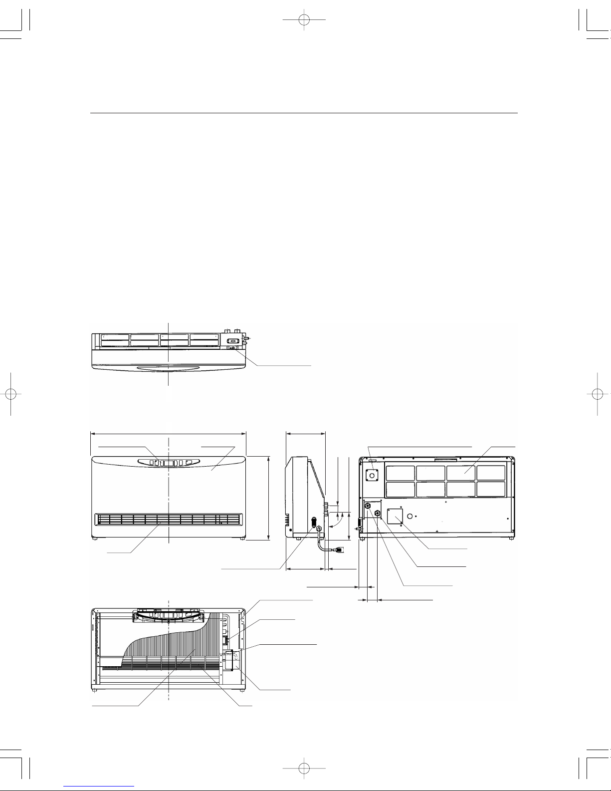
Operation panel Front panel Air filter
External output
(for circulation control or zone valve)
Main circuit board
Transformer
Thermistor
(Water Temperature)
Air release screw
Fan
Junction box
Water return
(NPT 1/2 female)
Water supply
(NPT 1/2 female)
Thermistor
(Room Temperature)
Louvers
Heat exchanger
Fan moter
28 - 3/8” (720 mm)
7 - 3/16”
(182 mm)
7 - 3/16”
(182 mm)
9/16”
(15 mm)
1-13/16” (46 mm)
1-9/16” (40 mm)
15 - 1/4” (387 mm)
4 - 7/8” (124 mm)
1-3/8” (35 mm)
90˚
SECTION B:
UNPACKING
UNPACKING
1. Unpack the unit carefully.
2. Check to see if there are any loose screws that may have occurred in transit.
3. Take accessories and the instruction manual out of the carton.
ACCESSORY PARTS
1. Installation and Operation Instructions
2. Warranty Card
3. Wall Fixing Kit (Wall bracket – 2 sets, Screw – 2 pcs., Wooden screw – 2 pcs.)
DIMENSIONAL OUTLINE
2
HC-20_US.qxd 14.7.1 9:13 ページ 2
The instructions which are contained in this manual are classified into the following two types, which are “WARNING”
and “CAUTION”. These instructions are intended to provide important information for safe operation.
“WARNING”
indicates the possibility of causing the user a fatal accident or serious injury if the unit is incorrectly
operated.
“CAUTION”
indicates the possibility of causing the user injuries or material damages if the unit is incorrectly
operated.
WARNING
1. Improper installation, adjustment, modification, or service and maintenance by an unauthorized person may cause
SERIOUS UNIT DAMAGE, BODILY INJURY, HAZARD OR PROPERTY DAMAGE. This unit should be installed by a
licensed, authorized person(s) due to the necessity of making electrical and water connections. Refer to the
installation and operation instructions for assistance, or consult your dealer for further information.
2. HAZARD OF ELECTRICAL SHOCK! Before removing any access panels of unit for service, make sure the
electrical supply to the unit is shut off. Failure to do this may result in HAZARD, SERIOUS BODILY INJURY, OR
PROPERTY DAMAGE.
3. Check and comply with all state, and local codes before beginning the installation.
CAUTION
1. Keep the area around the unit clean and free of flammable materials.
2. RISK OF FIRE AND ELECTRIC SHOCK. DO NOT apply any excessive force or pressure to the power supply cord.
Make sure the plug is free of dust. Be sure plug fits the receptacle securely.
SECTION C:
SAFETY TIPS FOR INSTALLATION
3
HC-20_US.qxd 14.7.1 9:13 ページ 3
WARNING: This unit must be installed in accordance with these instructions, local codes, ordinances and/or in the
absence of local codes National Plumbing standards.
Check and comply with all state and local codes before beginning the installation.
This unit should be installed by a licensed, authorized person(s) due to the necessity of making
electrical and water connections.
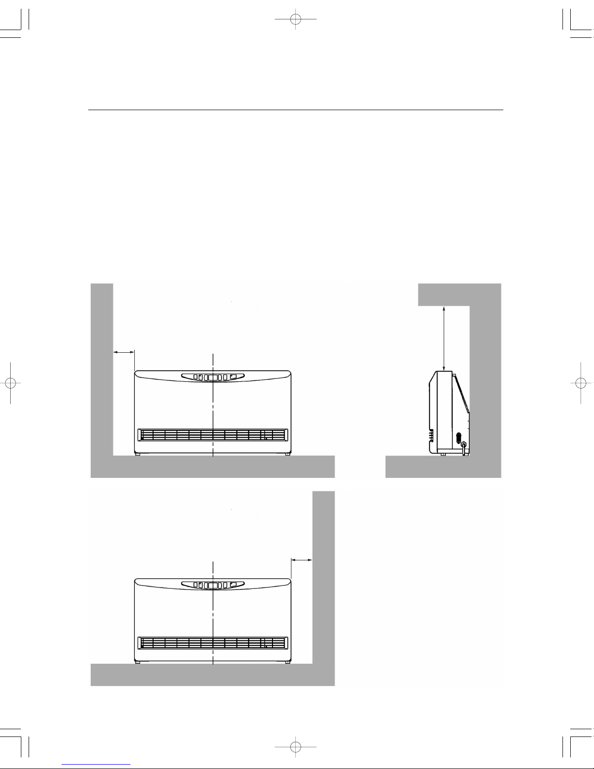
SELECTING A LOCATION
Select a place to install the unit where hot water and electric supply are easily available.
1. Select a place which is free of combustible substances.
2. Select a place where proper maintenance and repair can be provided for the unit after installation.
3. Install the unit on level floor.
NOTE: The unit may be installed on the wall directly.
Not less
than 4 in.
Not less than 12 in.
(1 ft.)
Not less
than 4 in.
SECTION D:
INSTALLATION
4
HC-20_US.qxd 14.7.1 9:13 ページ 4

Supply opening NPT 1/2” Female Return opening NPT 1/2” Female
Air Release Screw
PLUMBING
NOTE: Make sure the piping for the unit is laid out properly, and also check for any water leakage.
1. Install heat insulation material on the water piping to prevent heat loss.
2. Copper or polyethylene pipe should be used for connecting pipes.
3. It is recommended to install shut-off valves on the supply and return sides for easy removal.
4. It is recommended to install a bypass loop in the water pipes with a shut-off valve.
5.
Be sure to use anti-freezing solution, or non-scale block, or non-slime block, or corrosion-free water for the circulation
water.
Temperature of circulation water has to be less than 190˚F (87.8˚C)
Maximum allowable working pressure has to be less than 142 PSI
REMOVING TRAPPED AIR
When operating for the first time, air may be trapped in the system. To release the air out of the piping and the unit,
follow the procedures below.
1. To remove the air release cover, remove the two (2) screws.
2. Loosen the Air release screw by using the flat head screwdriver. Release the air out of the piping.
3. Tighten the Air release screw after removing all trapped air.
4. Immediately wipe off any spilled water.
5. Attach the Air release cover.
5
HC-20_US.qxd 14.7.1 9:13 ページ 5
 Loading...