

Page 1

toyota :: Toyota Truck Tundra Access Cab SR5
4WD V6-3.4L (5VZ-FE) (2000)
Page 2

> Relays and Modules > Relays and Modules - Accessories and Optional Equipment > Alarm Module, (Vehicle Antitheft) > Component Information > Technical Service Bulletins > Antitheft - Automatic Door Lock Feature
Programming
Alarm Module: Technical Service BulletinsAntitheft - Automatic Door Lock Feature Programming
BULLETIN NUMBER:AX005-00
DATE:April 14, 2000
TITLE:RS3OOO TVIP AUTOMATIC DOOR LOCK FEATURE PROGRAMMING
MODELS:All Models
Introduction
As a convenience feature, the RS3OOO TVIP system is programmed to automatically lock all of the vehicle's doors (for vehicles equipped with powerdoor locks) when the ignition key is turned to "ON" or "START", and unlock them when the key is turned back to "ACC" or "LOCK". The initial factorysetting of this programmable feature is "ON". For some customers however, this feature is not desirable due to instances of passenger lockout when thedriver enters the vehicle first and starts the ignition.
For vehicles equipped with RS3OOO TVIP, this bulletin advises the dealers to communicate the following information to the customers at vehicledelivery:
1. Inform the customers of the RS3OOO system's automatic (ignition controlled) door lock/unlock feature.
2. Inquire about the customers' preference for it to be set "ON" or "OFF".
3. Reprogram the feature's setting according to the customer's preference.
To change the feature's operation mode, follow the programming procedures.
Verification of the Dealer-Installed Option (DIO) or Port-Installed Option (PIO) RS3OOO TVIP System can easily be performed by identifying thestatus monitor and remote transmitter.
The remote transmitter has two buttons, Top and Bottom.
Page 3

> Relays and Modules > Relays and Modules - Accessories and Optional Equipment > Alarm Module, (Vehicle Antitheft) > Component Information > Technical Service
Bulletins > Antitheft - Automatic Door Lock Feature Programming > Page 8
Tundra Access Cab SR5 4WD V6-3.4L (5VZ-FE) (2000)
The status monitor has a Toyota label, LED, and microphone.
APPLICABLE VEHICLES
All models equipped with DIO or PIO RS3000 TVIP
Page 4

WARRANTY INFORMATION
PROGRAMMING PROCEDURE
AUTOMATIC (IGNITION-CONTROLLED) DOOR LOCKING/UNLOCKING FUNCTION
The factory setting for the AUTOMATIC DOOR LOCKING/UNLOCkING FUNCTION is "ON".
To change this feature's operation, follow the steps below:
1. Sit in the driver's seat with driver's door open.
2.
Insert the key into the ignition switch, and turn it to 'ON" position (not "ACC") 5 times (ON > LOCK > ON > LOCK> ON > LOCK > ON>LOCK > ON) within a 10 second period.
System Response: The STATUS MONITOR's LED turns on, and the PIEZO BUZZER sounds once.
NOTE:
You must perform the next steps within 30 seconds.
3. Select the customer's preferred operating mode.
Page 5

Page 6

> Relays and Modules > Relays and Modules - Accessories and Optional Equipment > Alarm Module, (Vehicle Antitheft) > Component Information > Technical Service Bulletins > Antitheft - Automatic Door Lock Feature
Programming > Page 9
Alarm Module: Technical Service BulletinsAntitheft - Control Module New Location & Mounting
ACCESSORIESAX006-00
Title:RS3000 TVIP ECU MOUNTING
Models:'00 Tundra
July 7, 2000
Introduction To improve mounting stability on 2000 MY Tundra vehicles equipped with a Post Production Option (PPO) or Dealer Installed Option (DIO); RS3000TVIP, the location of the V3 ECU was changed from the left cluster panel to the vehicle instrument panel cross-member on the right side of the steeringcolumn. The mounting method has changed from butyl tape to a solid bracket screwed to the V3 ECU. Refer to the installation instructions for details onthe installation.
Verification of the PPO and DIO RS3000 TVIP System can easily be performed by identifying the remote transmitter and status monitor.
Applicable Vehicles
^ All 2000 model year Tundra vehicles equipped with DIO or PPO RS3000 TVIP.
Parts Information
Page 7

> Relays and Modules > Relays and Modules - Accessories and Optional Equipment > Alarm Module, (Vehicle Antitheft) > Component Information > Technical Service
Bulletins > Antitheft - Automatic Door Lock Feature Programming > Page 10
Tundra Access Cab SR5 4WD V6-3.4L (5VZ-FE) (2000)
Warranty Information
Installation Instructions
These illustrations call out the change in location and new mounting method of the ECU.
Previous Method
Page 8

The Previous method was to insert the V3 ECU into the dash through the left cluster panel opening and secure it to the plastic using butyl tape.
New Method
1. Prepare the V3 ECU as described in the installation instructions.
2. Remove the connector block mounted near the firewall to the right side of the steering column.
3. Connect the V3 harness ECU connectors (10P, 10p, 4P) to the V3 ECU.
Page 9

4.
With the connectors facing left, slide the ECU mounting bracket over the existing stud bolt, then secure it and the connector block with thepreviously removed nut.
Page 10

> Relays and Modules > Relays and Modules - Accessories and Optional Equipment > Keyless Entry Module > Component Information > Technical Service Bulletins > Antitheft - Control Module New Location & Mounting
Keyless Entry Module: Technical Service BulletinsAntitheft - Control Module New Location & Mounting
ACCESSORIESAX006-00
Title:RS3000 TVIP ECU MOUNTING
Models:'00 Tundra
July 7, 2000
Introduction To improve mounting stability on 2000 MY Tundra vehicles equipped with a Post Production Option (PPO) or Dealer Installed Option (DIO); RS3000TVIP, the location of the V3 ECU was changed from the left cluster panel to the vehicle instrument panel cross-member on the right side of the steeringcolumn. The mounting method has changed from butyl tape to a solid bracket screwed to the V3 ECU. Refer to the installation instructions for details onthe installation.
Verification of the PPO and DIO RS3000 TVIP System can easily be performed by identifying the remote transmitter and status monitor.
Applicable Vehicles
^ All 2000 model year Tundra vehicles equipped with DIO or PPO RS3000 TVIP.
Parts Information
Page 11

> Relays and Modules > Relays and Modules - Accessories and Optional Equipment > Keyless Entry Module > Component Information > Technical Service Bulletins >
Antitheft - Control Module New Location & Mounting > Page 15
Tundra Access Cab SR5 4WD V6-3.4L (5VZ-FE) (2000)
Warranty Information
Installation Instructions
These illustrations call out the change in location and new mounting method of the ECU.
Previous Method
Page 12

The Previous method was to insert the V3 ECU into the dash through the left cluster panel opening and secure it to the plastic using butyl tape.
New Method
1. Prepare the V3 ECU as described in the installation instructions.
2. Remove the connector block mounted near the firewall to the right side of the steering column.
3. Connect the V3 harness ECU connectors (10P, 10p, 4P) to the V3 ECU.
Page 13

4.
With the connectors facing left, slide the ECU mounting bracket over the existing stud bolt, then secure it and the connector block with thepreviously removed nut.
Page 14

> Relays and Modules > Relays and Modules - Body and Frame > Keyless Entry Module > Component Information > Technical Service Bulletins > Antitheft - Control Module New Location & Mounting
Keyless Entry Module: Technical Service BulletinsAntitheft - Control Module New Location & Mounting
ACCESSORIESAX006-00
Title:RS3000 TVIP ECU MOUNTING
Models:'00 Tundra
July 7, 2000
Introduction To improve mounting stability on 2000 MY Tundra vehicles equipped with a Post Production Option (PPO) or Dealer Installed Option (DIO); RS3000TVIP, the location of the V3 ECU was changed from the left cluster panel to the vehicle instrument panel cross-member on the right side of the steeringcolumn. The mounting method has changed from butyl tape to a solid bracket screwed to the V3 ECU. Refer to the installation instructions for details onthe installation.
Verification of the PPO and DIO RS3000 TVIP System can easily be performed by identifying the remote transmitter and status monitor.
Applicable Vehicles
^ All 2000 model year Tundra vehicles equipped with DIO or PPO RS3000 TVIP.
Parts Information
Page 15

> Relays and Modules > Relays and Modules - Body and Frame > Keyless Entry Module > Component Information > Technical Service Bulletins > Antitheft - Control
Module New Location & Mounting > Page 21
Tundra Access Cab SR5 4WD V6-3.4L (5VZ-FE) (2000)
Warranty Information
Installation Instructions
These illustrations call out the change in location and new mounting method of the ECU.
Previous Method
Page 16

The Previous method was to insert the V3 ECU into the dash through the left cluster panel opening and secure it to the plastic using butyl tape.
New Method
1. Prepare the V3 ECU as described in the installation instructions.
2. Remove the connector block mounted near the firewall to the right side of the steering column.
3. Connect the V3 harness ECU connectors (10P, 10p, 4P) to the V3 ECU.
Page 17

4.
With the connectors facing left, slide the ECU mounting bracket over the existing stud bolt, then secure it and the connector block with thepreviously removed nut.
Page 18

> Relays and Modules > Relays and Modules - Body and Frame > Power Door Lock Relay > Component Information > Testing and Inspection
Power Door Lock Relay: Testing and Inspection
INSPECT INTEGRATION RELAY CIRCUIT
Page 19

> Relays and Modules > Relays and Modules - Body and Frame > Power Door Lock Relay > Component Information > Testing and Inspection > Page 25
Tundra Access Cab SR5 4WD V6-3.4L (5VZ-FE) (2000)
a. Disconnect the connector from the integration relay and inspect the connector on the wire harness side, as shown in the chart.
Page 20

b. Disconnect the connector from integration relay and remove the front cover on the junction block, as show in the chart.
If continuity is not as specified, replace the driver side junction block.
Page 21

Page 22

> Relays and Modules > Relays and Modules - Body and Frame > Trailer Towing Relay > Component Information > Technical Service Bulletins > Trailer Towing - Wire Harness Power Converter
Trailer Towing Relay: Technical Service BulletinsTrailer Towing - Wire Harness Power Converter
ACCESSORIESAX008-00
September 29, 2000
Title:TRAILER TOWING WIRE HARNESS POWER CONVERTER
Models:'00 Tundra
Introduction To simplify application, ordering and serviceability, Toyota is consolidating the Trailer Towing Wire Harness Power Converter vendor for both hitchand bumper towing applications of the 2000 model year Tundra.
Applicable Vehicles^
2000 model year Tundra vehicles with a Toyota Trailer Wire Harness Converter.
Installation Procedure
Installation instructions are included in the Converter Service kit.
Parts Information
Page 23

Warranty Information
Applicable Warranty*:This repair is covered under the Toyota Basic Warranty. This warranty is in effect for 36 months or 36,000 miles, whichever occurs first, from thevehicle's in-service date.
* Warranty application is limited to correction of a problem based upon a customer's specific complaint.
Page 24

> Relays and Modules > Relays and Modules - Brakes and Traction Control > Brake Fluid Pump Relay > Component Information > Description and Operation
Brake Fluid Pump Relay: Description and Operation
ABS Motor Relay
ABS With Electronic Brake Force Distribution
ON
The ABS motor relay supplies power to the ABS pump motor. When the ABS is activated, the ECU switches the ABS motor relay and operates theABS pump motor.
ABS With EBD, BA, TRAC & VSC Systems
The ABS motor relay supplies power to the brake actuator pump motor. While the ABS & BA & TRAC & VSC are activated, the ECU switches themotor relay and operates the brake actuator pump motor.ON
ABS With BA, TRAC & VSC Systems
The ABS motor and ABS motor 2 relay supplies power to the hydraulic brake booster pump motor. While the ABS & BA & TRAC & VSC areactivated, the ECU switches the motor relay and operates the hydraulic brake booster pump motor.ON
Anti-Lock Brake System
The ABS motor relay supplies power to the ABS pump motor or hydraulic brake booster pump. While the ABS is activated, the ECU switches the ABSmotor relay and operates the ABS pump motor.ON
ABS With TRAC System
The ABS & TRAC motor relay supplies power to the ABS & TRAC pump motor. While the ABS is activated, the ECU switches the ABS & TRACmotor relay and operates the ABS & TRAC pump motor.ON
Page 25

Page 26

> Relays and Modules > Relays and Modules - Brakes and Traction Control > Brake Fluid Solenoid Valve Relay > Component Information > Description and Operation
Brake Fluid Solenoid Valve Relay: Description and Operation
ABS Solenoid Relay
This relay supplies power to each ABS solenoid. After the ignition switch is turned , if the initial check is OK, the relay goes on.ON
Page 27

Page 28

> Relays and Modules > Relays and Modules - HVAC > Blower Motor Relay > Component Information > Testing and Inspection
Blower Motor Relay: Testing and Inspection
1. REMOVE HEATER MAIN RELAY FROM NO.2 RELAY BLOCK
2. INSPECT HEATER MAIN RELAY (Making: HTR) CONTINUITY
If continuity is not as specified, replace the relay.
Page 29

Page 30

> Relays and Modules > Relays and Modules - Lighting and Horns > Backup Lamp Relay > Component Information > Testing and Inspection
Backup Lamp Relay: Testing and Inspection
INSPECT BACK-UP LIGHT RELAY CONTINUITYIf continuity is not as specified, replace the relay.
Page 31

Page 32

> Relays and Modules > Relays and Modules - Lighting and Horns > Daytime Running Lamp Relay > Component Information > Testing and Inspection
Daytime Running Lamp Relay: Testing and Inspection
Terminal Identification
INSPECT DAYTIME RUNNING LIGHT RELAY CIRCUITConnector DisconnectedDisconnect the connector from the relay and inspect the connector on the wire harness side.If circuit is as specified, perform inspections.
Page 33

> Relays and Modules > Relays and Modules - Lighting and Horns > Daytime Running Lamp Relay > Component Information > Testing and Inspection > Page 48
Tundra Access Cab SR5 4WD V6-3.4L (5VZ-FE) (2000)
INSPECT DAYTIME RUNNING LIGHT RELAY CIRCUITConnector ConnectedConnect the wire harness side connector to the relay and inspect wire harness side connector from the back side, as shown.If circuit is not as specified, trying replacing the relay with a new one.
Page 34

INSPECT DAYTIME RUNNING LIGHT RELAY NO.4 CONTINUITYIf continuity is not as specified, replace the relay.
Page 35

Page 36

> Relays and Modules> Relays and Modules - Lighting and Horns> Fog LIght Relay <--> [Fog/Driving Lamp Relay] > Component Information > Testing and Inspection
Fog LIght Relay: Testing and Inspection
Fog Light System
INSPECT FOG LIGHT RELAY CONTINUITYIf continuity is not as specified, replace the relay.
Page 37

Page 38

> Relays and Modules > Relays and Modules - Lighting and Horns > Automatic Light Control System <--> [Headlamp Control Module] > Component Information > Locations > Component Locations
Automatic Light Control System: Component Locations
Page 39

Page 40

> Relays and Modules > Relays and Modules - Lighting and Horns > Automatic Light Control System <--> [Headlamp Control Module] > Component Information > Locations > Component Locations > Page 56
Automatic Light Control System: Connector Locations
Page 41

Page 42

> Relays and Modules > Relays and Modules - Lighting and Horns > Automatic Light Control System <--> [Headlamp Control Module] > Component Information > Locations > Component Locations > Page 57
Automatic Light Control System: Fuse and Fusible Link Locations
Page 43

Page 44

> Relays and Modules > Relays and Modules - Lighting and Horns > Automatic Light Control System <--> [Headlamp Control Module] > Component Information > Locations > Component Locations > Page 58
Automatic Light Control System: Ground Locations
Page 45

Page 46

> Relays and Modules > Relays and Modules - Lighting and Horns > Automatic Light Control System <--> [Headlamp Control Module] > Component Information > Locations > Component Locations > Page 59
Automatic Light Control System: Locations
Component Locations
Connector Locations
Fuse and Fusible Link Locations
Ground Locations
Splice Locations
Harness Locations
Page 47

Page 48

> Relays and Modules > Relays and Modules - Lighting and Horns > Automatic Light Control System <--> [Headlamp Control Module] > Component Information > Diagrams > Diagram Information and Instructions
Automatic Light Control System: Diagram Information and Instructions
Key to Diagrams
Page 49

> Relays and Modules > Relays and Modules - Lighting and Horns > Automatic Light Control System <--> [Headlamp Control Module] > Component Information >
Diagrams > Diagram Information and Instructions > Page 62
Tundra Access Cab SR5 4WD V6-3.4L (5VZ-FE) (2000)
Key to Diagrams
System Title.A:
Indicates a Relay Block. No shading is used and only the Relay Block No. is shown to distinguish it from the J/BB:
Example: (1) Indicates Relay Block No.1
( ) is used to indicate different wiring and connector, etc. when the vehicle model, engine type, or specification is different.C:
Page 50

Indicates related system.D:
Wiring Harness Connector
Indicates the wiring harness and wiring harness connector. The wiring harness with male terminal is shown with arrows (V).E:
Outside numerals are pin numbers.The first letter of the code for each wiring harness and wiring harness connector(s) indicates the component's location, e.g, "E" for the EngineCompartment, "I" for the Instrument Panel and Surrounding area, and "B" for the Body and Surrounding area.When more than one code has the first and second letters in common, followed by numbers (e.g, IH1, 1H2), this indicates the same type of wiringharness and wiring harness connector.
Represents a part (all parts are shown in sky blue). The code is the same as the code used in parts position.F:
Junction Block (The number in the circle is the J/B No. and the connector code is shown beside it). Junction Blocks are shaded to clearly separateG:
them from other parts.
When 2 parts both use one connector in common, the parts connector name used in the wire routing section is shown in square brackets [ ].H:
Wiring Color
Indicates the wiring color.I:
Wire colors are indicated by an alphabetical code.
B = Black
BR = Brown
G = Green
GR = Gray
L = Blue
LG = Light Green
O = Orange
P = Pink
R = Red
SB = Sky Blue
Page 51

> Relays and Modules > Relays and Modules - Lighting and Horns > Automatic Light Control System <--> [Headlamp Control Module] > Component Information >
Diagrams > Diagram Information and Instructions > Page 63
Tundra Access Cab SR5 4WD V6-3.4L (5VZ-FE) (2000)
V = Violet
W = White
Y = Yellow
The first letter indicates the basic wire color and the second letter indicates the color of the stripe.
Page 52

Splice Point
Indicates a wiring Splice Point (Codes are "E"for the Engine Room, "I" for the Instrument Panel, and "B" for the Body).J:
The Location of splice Point I 5 is indicated by the shaded section.
Indicates a shielded cable.K:
Indicates the pin number of the connector.L:
The numbering system is different for female and male connectors.
Indicates a ground point.M:
The first letter of the code for each ground point(s) indicates the component's location, e.g, "E" for the Engine Compartment, "I" for the InstrumentPanel and Surrounding area, and "B" for the Body and Surrounding area.
N: Page No.
How to Read Ground Points
How to Read Ground Points
Page 53

> Relays and Modules > Relays and Modules - Lighting and Horns > Automatic Light Control System <--> [Headlamp Control Module] > Component Information >
Diagrams > Diagram Information and Instructions > Page 64
Tundra Access Cab SR5 4WD V6-3.4L (5VZ-FE) (2000)
Page 54

The ground points circuit diagram shows the connections from all major parts to the respective ground points.
When troubleshooting a faulty ground point checking the system circuits which use a common ground may help you identify the problem ground quickly.
Page 55

> Relays and Modules > Relays and Modules - Lighting and Horns > Automatic Light Control System <--> [Headlamp Control Module] > Component Information >
Diagrams > Diagram Information and Instructions > Page 65
Tundra Access Cab SR5 4WD V6-3.4L (5VZ-FE) (2000)
The relationship between ground points (EA, IB and IC shown) can also be checked this way.
How to Read Power Source
How to Read Power Source
Page 56

The "Current Flow Chart", describes which parts each power source (fuses, fusible links, and circuit breakers) transmits current to.
The chart shows the route by which current flows from the battery to each electrical source (Fusible Link, Circuit Breaker, Fuse, etc.) and other parts.
In the Power Source circuit diagram, the conditions when battery power is supplied to each system are explained. Since all System Circuit diagrams startfrom the power source, the power source system must be fully understood.
Page 57

> Relays and Modules > Relays and Modules - Lighting and Horns > Automatic Light Control System <--> [Headlamp Control Module] > Component Information >
Diagrams > Diagram Information and Instructions > Page 66
Tundra Access Cab SR5 4WD V6-3.4L (5VZ-FE) (2000)
Page 58

Page 59

> Relays and Modules > Relays and Modules - Lighting and Horns > Automatic Light Control System <--> [Headlamp Control Module] > Component Information >
Diagrams > Diagram Information and Instructions > Page 67
Tundra Access Cab SR5 4WD V6-3.4L (5VZ-FE) (2000)
Page 60

Page 61

Page 62
> Relays and Modules > Relays and Modules - Lighting and Horns > Automatic Light Control System <--> [Headlamp Control Module] > Component Information > Diagrams > Diagram Information and Instructions > Page 68
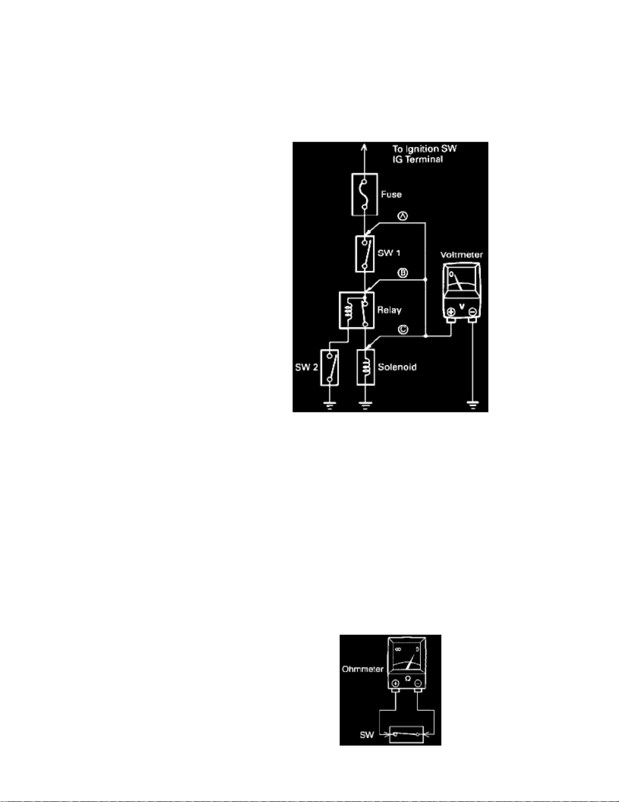
Automatic Light Control System: Diagnostic Aids
Voltage Check
Voltage Check
Voltage Check
A. Establish conditions in which voltage is present at the check point.
ON
Example:A - Ignition SW B - Ignition SW and SW 1 C - Ignition SW, SW 1 and Relay (SW 2 )ON ON OFF
B. Using a voltmeter, connect the negative lead to a good ground point or negative battery terminal, and the positive lead to the connector or
Continuity and Resistance Check
Continuity and Resistance Check
Page 63

> Relays and Modules > Relays and Modules - Lighting and Horns > Automatic Light Control System <--> [Headlamp Control Module] > Component Information >
Diagrams > Diagram Information and Instructions > Page 69
Tundra Access Cab SR5 4WD V6-3.4L (5VZ-FE) (2000)
component terminal.This check can be done with a test light instead of a voltmeter.
Continuity And Resistance Check
A. Disconnect the battery terminal or wire so there is no voltage between the check points.B. Contact the two leads of an ohmmeter to each of the check points.
Page 64

Continuity And Resistance Check
If the circuit has diodes, reverse the two leads and check again.
When contacting the negative lead to the diode positive side and the positive lead to the negative side, there should be continuity.
When contacting the two leads in reverse, there should be no continuity.
Continuity And Resistance Check
C. Use a volt/ohmmeter with high impedance ( minimum) for troubleshooting of the electrical circuit.10 k ohm/V
Finding A Short Circuit
Finding A Short Circuit
Page 65

> Relays and Modules > Relays and Modules - Lighting and Horns > Automatic Light Control System <--> [Headlamp Control Module] > Component Information >
Diagrams > Diagram Information and Instructions > Page 70
Tundra Access Cab SR5 4WD V6-3.4L (5VZ-FE) (2000)
Finding A Short Circuit
A. Remove the blown fuse and disconnect all loads of the fuse.
Page 66

B. Connect a test light in place of the fuse.C. Establish conditions in which the lest light comes .ON
ON
Example:A - Ignition SW B - Ignition SW and SW 1 C - Ignition SW, SW 1 and Relay (Connect the Relay) and SW 2 (or Disconnect SW 2)ON ON OFF
D. Disconnect and reconnect the connectors while watching the test light.
The short lies between the connector where the test light stays lit and the connector where the light goes out.
E. Find the exact location of the short by lightly shaking the problem wire along the body.
CAUTION:
a. Do not open the cover or the case of the ECU unless absolutely necessary. (If the IC terminals are touched, the IC may be destroyed by
static electricity.)
b. When replacing the internal mechanism (ECU part) of the digital meter, be careful that no part of your body or clothing comes in contact
with the terminals of leads from the IC, etc. of the replacement part (spare part).
How to Replace Terminal
HOW TO REPLACE TERMINAL (with terminal retainer or secondary locking device)
Special Tool
1. PREPARE THE SPECIAL TOOL
To remove the terminal from the connector, please construct and use the special tool or like object shown.HINT:
2. DISCONNECT CONNECTOR
Page 67

> Relays and Modules > Relays and Modules - Lighting and Horns > Automatic Light Control System <--> [Headlamp Control Module] > Component Information >
Diagrams > Diagram Information and Instructions > Page 71
Tundra Access Cab SR5 4WD V6-3.4L (5VZ-FE) (2000)
3. DISENGAGE THE SECONDARY LOCKING DEVICE OR TERMINAL RETAINER.
a. Locking device must be disengaged before the terminal locking clip can be released and the terminal removed from the connector.b. Use a special tool or the terminal pick to unlock the secondary locking device or terminal retainer.
Do not remove the terminal retainer from connector body.NOTE:
A: For Non-Waterproof Type Connector
HINT:
The needle insertion position varies according to the connector's shape (number of terminals etc.), so check the position beforeinserting it.
Page 68

Non-Waterproof Type Connector
Raise the terminal retainer up to the temporary lock position."Case 1"
Non-Waterproof Type Connector
Page 69

> Relays and Modules > Relays and Modules - Lighting and Horns > Automatic Light Control System <--> [Headlamp Control Module] > Component Information >
Diagrams > Diagram Information and Instructions > Page 72
Tundra Access Cab SR5 4WD V6-3.4L (5VZ-FE) (2000)
Open the secondary locking device."Case 2"
Page 70

Waterproof Type Connector
B: For Waterproof Type Connector
Terminal retainer color is different according to connector body.HINT:
Example:Terminal Retainer : Connector BodyBlack or White
: Gray
Black or White : Dark Gray
Gray or White : Black
Waterproof Type Connector
Type where terminal retainer is pulled up to the temporary lock position (Pull Type)."Case 1"
Insert the special tool into the terminal retainer access hole (Mark) and pull the terminal retainer up to the temporary lock position.
HINT:
The needle insertion position varies according to the connector's shape (Number of terminals etc.), so check the position beforeinserting it.
Page 71

> Relays and Modules > Relays and Modules - Lighting and Horns > Automatic Light Control System <--> [Headlamp Control Module] > Component Information >
Diagrams > Diagram Information and Instructions > Page 73
Tundra Access Cab SR5 4WD V6-3.4L (5VZ-FE) (2000)
Waterproof Type Connector
Type which cannot be pulled as far as Power Lock insert the tool straight into the access hole of terminal retainer as shown."Case 2"
Page 72

Terminal Retainer
Push the terminal retainer down to the temporary lock position.
c. Release the locking lug from terminal and pull the terminal out from rear.
4. INSTALL TERMINAL TO CONNECTOR
Page 73

> Relays and Modules > Relays and Modules - Lighting and Horns > Automatic Light Control System <--> [Headlamp Control Module] > Component Information >
Diagrams > Diagram Information and Instructions > Page 74
Tundra Access Cab SR5 4WD V6-3.4L (5VZ-FE) (2000)
a. Insert the terminal.
HINT:
1. Make sure the terminal is positioned correctly.2. Insert the terminal until the locking lug locks firmly.3. Insert the terminal with terminal retainer in the temporary lock position.
Page 74

b. Push the secondary locking device or terminal retainer in to the full lock position.
5. CONNECT CONNECTOR
Disconnection of Male and Female Connectors
Disconnection of Male and Female Connectors
Disconnection Of Male And Female Connectors
To pull apart the connectors, pull on the connector itself, not the wire harness.
Check to see what kind of connector you are disconnecting before pulling apart.HINT:
Page 75

Page 76

> Relays and Modules > Relays and Modules - Lighting and Horns > Automatic Light Control System <--> [Headlamp Control Module] > Component Information > Diagrams > Diagram Information and Instructions > Page 75
Automatic Light Control System: Electrical Diagrams
Service Hints
HEAD RELAY
2-1
HEAD FLASH
: Closed with the light control SW at position or the dimmer SW at position: Closed with the engine running and the parking brake lever released (W/ daytime running light)
C15 LIGHT CONTROL SW [COMB. SW]
13-16
: Closed with light control SW at positionHEAD
14-16
: Closed with light control SW at or positionTAIL HEAD
D16 DOOR COURTESY SW FRONT LH
1-GROUND: Continuity with the front LH door open
INTEGRATION RELAY
9-GROUND : Approx. with the ignition SW at position12 volts ON
14-GROUND: Continuity with the front LH door open3, 6-GROUND
: Always approx. 12 volts
8-GROUND : Always continuity
Page 77

> Relays and Modules > Relays and Modules - Lighting and Horns > Automatic Light Control System <--> [Headlamp Control Module] > Component Information >
Diagrams > Diagram Information and Instructions > Page 76
Tundra Access Cab SR5 4WD V6-3.4L (5VZ-FE) (2000)
Page 78

Page 79

Page 80

> Relays and Modules > Relays and Modules - Lighting and Horns > Automatic Light Control System <--> [Headlamp Control Module] > Component Information > Diagrams > Page 77
Automatic Light Control System: Description and Operation
TERMINAL 9
TERMINAL 6
With the ignition SW turned on, the current flows to of the integration relay through ECU IG fuse.Voltage is applied at all times to of the integration relay through the TAIL fuse, and through the HEAD relay coil side (W/O daytimerunning light) or through the daytime running light relay (Main) (W/ daytime running light).
1. NORMAL LIGHTING OPERATION
TERMINAL 6 TERMINAL 14 TERMINAL 16
TERMINAL 13 TERMINAL 16
<Turn taillight on>With the light control SW turned to TAIL position, a signal is input into the integration relay. Due to this signal, the current flowing to of the relay flows to of the light control SW to to GROUND, and taillights to turn on.<Turn headlight on>With the light control SW turned to HEAD position, a signal is input into the integration relay. Due to this signal, the current flowing to the relayflows to of the light control SW to to GROUND in the headlight circuit, and causes taillight and HEAD relay toturn the lights on.The taillight circuit is same as above.
2. LIGHT AUTO TURN OFF OPERATION
TERMINAL 9
TERMINAL 14 TERMINAL 6
With light on and ignition SW turned off (Input signal goes to of the relay), when the driver's door is opened (Input signal goes to of the relay), the relay operates and the current is cut off which flows from of the relay to taillight circuit andheadlight circuit.As a result, all lights are turned off automatically.
Page 81

Page 82

> Relays and Modules > Relays and Modules - Lighting and Horns > Headlamp Relay > Component Information > Testing and Inspection
Headlamp Relay: Testing and Inspection
INSPECT HEADLIGHT CONTROL RELAY CONTINUITY
If continuity is not as specified, replace the relay.
Page 83

Page 84

> Relays and Modules > Relays and Modules - Lighting and Horns > Tail Lamp Relay > Component Information > Testing and Inspection
Tail Lamp Relay: Testing and Inspection
w/Daytime running light:
INSPECT TAILLIGHT DIMMER RELAY CONTINUITYIf continuity is not as specified, replace the relay.
Page 85

Page 86

> Relays and Modules > Relays and Modules - Power and Ground Distribution > Relay Box > Component Information > Locations
Relay Box: Locations
Page 87

> Relays and Modules > Relays and Modules - Power and Ground Distribution > Relay Box > Component Information > Locations > Page 88
Tundra Access Cab SR5 4WD V6-3.4L (5VZ-FE) (2000)
Driver Side J/B & Integration Relay
Page 88

Driver Side J/B & Integration Relay
Page 89

> Relays and Modules > Relays and Modules - Power and Ground Distribution > Relay Box > Component Information > Locations > Page 89
Tundra Access Cab SR5 4WD V6-3.4L (5VZ-FE) (2000)
Page 90

Page 91

> Relays and Modules > Relays and Modules - Power and Ground Distribution > Relay Box > Component Information > Locations > Page 90
Tundra Access Cab SR5 4WD V6-3.4L (5VZ-FE) (2000)
Engine Room R/B
Details
Page 92

Engine Compartment
Instrument Panel
Locations
Page 93

Page 94

> Relays and Modules > Relays and Modules - Power and Ground Distribution > Relay Box > Component Information > Locations > Page 91
Engine Rool Relay Block
Page 95

Page 96

> Relays and Modules > Relays and Modules - Powertrain Management > Relays and Modules - Computers and Control Systems > Engine Control Module > Component Information > Technical Service Bulletins > Engine/
Transmission Controls - Resetting ECM Memory
Engine Control Module: Technical Service BulletinsEngine/Transmission Controls - Resetting ECM Memory
TRANSMISSION & CLUTCHTC002-03REVISED
Title:ECM RESET MEMORY FUNCTION
Models:'00 - '05 All Models
June 10, 2003
:TSB REVISION NOTICE
^
December 20, 2004: Applicable Vehicles section has been updated - 2004 and 2005 model years added, models and model years updated forvarious models; and Reset Procedure 2 has been revised.
^ January 16, 2004: Tundra vehicles were added to the Applicable Vehicles chart.
^ December 17, 2003: T-100 vehicles were removed from the Applicable Vehicles chart.
Previous versions of this TSB should be discarded.
Introduction
Whenever an automatic transmission is replaced, overhauled or individual components are replaced, use this procedure to clear Engine Control Module(ECM, SAE term: Powertrain Control Module, PCM) "Learned Values" to minimize subsequent performance concerns.
:CAUTION
Failure to follow the procedure below may lengthen the time to readjust the ECM "Learned Values," potentially resulting in performance concerns.
Page 97

> Relays and Modules > Relays and Modules - Powertrain Management > Relays and Modules - Computers and Control Systems > Engine Control Module > Component
Information > Technical Service Bulletins > Engine/Transmission Controls - Resetting ECM Memory > Page 98
Tundra Access Cab SR5 4WD V6-3.4L (5VZ-FE) (2000)
Required SSTs
Warranty Information
Applicable Vehicles
Page 98

Refer to Reset Procedure 1 for the vehicles with Electronically Controlled Automatic Transmissions:
Page 99

> Relays and Modules > Relays and Modules - Powertrain Management > Relays and Modules - Computers and Control Systems > Engine Control Module > Component
Information > Technical Service Bulletins > Engine/Transmission Controls - Resetting ECM Memory > Page 99
Tundra Access Cab SR5 4WD V6-3.4L (5VZ-FE) (2000)
Page 100

Refer to Reset Procedure 2 for the vehicles with Electronically Controlled Automatic Transmissions:
Reset Procedure 1
1. Connect the Toyota Diagnostic Tester to the vehicle.
 Loading...