

Page 1

Last Modified: 3-27-2012 6.4 F From: 201203
Model Year: 2013 Model: FR-S Doc ID: RM0000010EX1UGX
Title: FOREWORD / CAUTION / SECTION: FOREWORD: CAUTION (2013 FR-S)
CAUTION
This contents does not include all the necessary items about repair and service. This manual is
made for the use of persons who have special techniques and certifications. If non-specialized or
uncertified technicians perform repairs or service only using this manual or without proper
equipment or tools, this may cause severe injury to you or other persons nearby and also cause
damage to your customer's vehicle.
In order to prevent dangerous operation and damage to your customer's vehicle, be sure to follow
the instructions shown below.
This contents must be read thoroughly. It is especially important to have a good
understanding of all the contents written in the PRECAUTION of "INTRODUCTION"
section.
The service method written in this manual is very effective to perform repair and service.
When performing the operations following the procedures using this manual, be sure to
use tools specified and recommended. If using non-specified or tools other than
recommended tools and service methods, be sure to confirm the safety of the technicians
and that there is no possibility of causing personal injury or damage to the customer's
vehicle before starting the operation.
If part replacement is necessary, the part must be replaced with the same part number
or equivalent part. Do not replace it with an inferior quality part.
It is important to note that this manual contains various "Cautions" and "Notices" that
must be carefully observed in order to reduce the risk of personal injury during service or
repair, or reduce the possibility that improper service or repair may damage the vehicle
or render it unsafe. It is also important to understand that these "Cautions" and
"Notices" are not exaggerations and are possible hazardous consequences that might
result from failure to follow these instructions.
Page 2

Last Modified: 3-27-2012 6.4 F From: 201203
Model Year: 2013 Model: FR-S Doc ID: RM0000010EW2RZX
Title: FOREWORD / CAUTION / SECTION: FOREWORD: FOREWORD (2013 FR-S)
FOREWORD
This is Volume 1 of the 2013 SCION FR-S manual. There are three volumes to this manual. The
sections included in each volume are indicated by black type in the Section Index. Use the Section
Index of each volume to find the volume with the section you need.
Applicable models ZN6 series
Please note that the publications below have also been prepared as relevant service manuals for the
components and system in these vehicles.
MANUAL NAME PUB. NO.
2013 SCION FR-S Electrical Wiring Diagram EM20S0U
2013 SCION FR-S New Car Features NM20S0U
All information in this manual is based on the latest product information at the time of publication.
However, specifications and procedures are subject to change without notice. For the most current
information available, refer to the Toyota Technical Information System (TIS) online at dealership
locations or on the Internet at http://techinfo.toyota.com.
If you find any failures in this manual, you are kindly requested to inform us by using the report
form on the next page.
Repair Manual Quality Report
Att.) Service Manager, Your Distributor
Page 3

Page 4

Last Modified: 3-27-2012 6.4 F From: 201203
Model Year: 2013 Model: FR-S Doc ID: RM000000UYV0BHX
Title: INTRODUCTION: HOW TO USE THIS MANUAL: GENERAL INFORMATION (2013 FR-S)
GENERAL INFORMATION
1. GENERAL DESCRIPTION
(a) This manual is written in accordance with SAE J2008.
(b) Repair operations can be separated mainly into the following 3 processes:
(1) Diagnosis
(2) Removing/Installing, Replacing, Disassembling/Reassembling, Checking and Adjusting
(3) Final Inspection
(c) The following procedure is omitted from this manual. However, this procedure must be performed.
(1) Use a jack or lift to perform operations.
(2) Clean all removed parts.
(3) Perform a visual check before and after performing any work.
2. INDEX
(a) An alphabetical INDEX section is provided at the end of the manual as a reference to help find the
item to be repaired.
3. PREPARATION
(a) Use of Special Service Tools (SST) and Special Service Materials (SSM) may be required, depending
on the repair procedure. Be sure to use SST and SSM when they are required and follow the work
procedure properly. A list of SST and SSM is in the "Preparation" section of this manual.
4. REPAIR PROCEDURES
(a) A component illustration is placed under the title where necessary.
(b) Non-reusable parts, grease application areas, precoated parts and torque specifications are noted
in the component illustrations.
The following illustration is an example.
Page 5

(c) Torque specifications, grease application areas and non-reusable parts are emphasized in the
procedures.
HINT:
There are cases where such information can only be explained by using an illustration. In these cases,
torque, oil and other information are described in the illustration.
(d) Only items with key points are described in the text. What to do and other details are explained
using illustrations next to the text. Both the text and illustrations are accompanied by standard
values and notices.
Illustration What to do and where to do it
Task heading What work will be performed
Explanation
text
(e) Illustrations of similar vehicle models are sometimes used. In these cases, minor details may be
different from the actual vehicle.
(f) Procedures are presented in a step-by-step format.
How to perform the task
Information such as specifications and warnings, which are written in boldface
text
5. SERVICE SPECIFICATIONS
(a) Specifications are presented in boldface text throughout the manual. The specifications are also
found in the "Service Specifications" section for reference.
6. TERM DEFINITIONS
CAUTION Possibility of injury to you or other people.
NOTICE Possibility of damage to components being repaired.
HINT Provides additional information to help you perform repairs.
7. INTERNATIONAL SYSTEM OF UNITS
Page 6

(a) The units used in this manual comply with the International System of Units (SI UNIT) standard.
Other units from the metric system and the English systems are also provided.
Example:
Torque: 30 N·m (310 kgf·cm, 22ft·lbf)
Page 7

Last Modified: 3-27-2012 6.4 F From: 201203
Model Year: 2013 Model: FR-S Doc ID: RM000000UZB09AX
Title: INTRODUCTION: TERMS: ABBREVIATIONS USED IN MANUAL (2013 FR-S)
ABBREVIATIONS USED IN MANUAL
ABBREVIATION MEANING
ABS Anti-Lock Brake System
A/C Air Conditioner
AC Alternating Current
ACC Accessory
ACIS Acoustic Control Induction System
ACM Active Control Engine Mount
ACSD Automatic Cold Start Device
ACT Actuator
A.D.D Automatic Disconnecting Differential
ADM P.T. Astra Daihatsu Motor
A/F Air-Fuel Ratio
AFS Adaptive Front-Lighting System
AHC Active Height Control Suspension
AID Air Injection Control Driver
ALR Automatic Locking Retractor
ALT Alternator
AMP Amplifier
ANT Antenna
ASG Automated Sequential Gearbox
ASL Automatic Sound Levelizer
ASSB Assembly Services Sdn. Bhd.
A/T, ATM Automatic Transmission (Transaxle)
A-TRAC, A-TRC Active Traction Control
ATDC After Top Dead Center
ATF Automatic Transmission Fluid
AUTO Automatic
AUX Auxiliary
AVG Average
AVS Adaptive Variable Suspension
AWD All Wheel Drive
B+, +B Battery Voltage
Page 8

BA Brake Assist
BACS Boost Altitude Compensation System
BATT Battery
BDC Bottom Dead Center
B/L Bi-Level
B/S Bore-Stroke Ratio
BTDC Before Top Dead Center
BVSV Bimetallic Vacuum Switching Valve
Calif. California
CAN Controller Area Network
CB Circuit Breaker
CCM Carbon Ceramic Material
CCo Catalytic Converter for Oxidation
CCV Canister Closed Valve
CD Compact Disc
CF Cornering Force
CG Center of Gravity
CH Channel
CKD Complete Knock Down
CNG Compressed Natural Gas
COMB. Combination
CPS Combustion Pressure Sensor
CPU Central Processing Unit
CRAWL Crawl Control
CRS Child Restraint System
CTR Center
C/V Check Valve
CV Control Valve
CVT Continuously Variable Transmission (Transaxle)
CW Curb Weight
DC Direct Current
DEF Defogger
DFL Deflector
DIFF. Differential
DIFF. LOCK Differential Lock
D/INJ Direct Injection
DLC Data Link Connector
Page 9

DLI Distributorless Ignition
DOHC Double Overhead Camshaft
DP Dash Pot
DS Dead Soak
DSP Digital Signal Processor
DTC Diagnostic Trouble Code
DVD Digital Versatile Disc
EBD Electric Brake Force Distribution
EC Electrochromic
ECAM Engine Control And Measurement System
ECD Electronically Controlled Diesel
ECDY Eddy Current Dynamometer
ECT Electronic Controlled Automatic Transmission
ECU Electronic Control Unit
ED Electro-Deposited
EDU Electronic Driving Unit
EDIC Electric Diesel Injection Control
EFI Electronic Fuel Injection
E/G Engine
EGR Exhaust Gas Recirculation
ELR Emergency Locking Retractor
EMPS Electric Motor Power Steering
EPS Electric Power Steering
ENG Engine
ES Easy & Smooth
ESA Electronic Spark Advance
EVAP Evaporative Emission Control
E-VRV Electric Vacuum Regulating Valve
EX Exhaust
FE Fuel Economy
FF Front-Engine-Front-Wheel-Drive
F/G Fuel Gauge
FIPG Formed In Place Gasket
FL
F/P Fuel Pump
FR
Fusible Link
Front Left
Front
Page 10

Front Right
F/W Flywheel
FW/D Flywheel Damper
FWD Front Wheel Drive
GAS Gasoline
GND Ground
GPS Global Positioning System
GSA Gear Shift Actuator
GTMC Gac Toyota Motor Co., Ltd.
GTS Global TechStream
H/B Hatchback
H-FUSE High Current Fuse
HID High Intensity Discharge (Headlight)
HPU Hydraulic Power Unit
HSG Housing
HT Hard Top
HV Hybrid Vehicle
HWS Heated Windshield System
IC Integrated Circuit
IDI Indirect Diesel Injection
IFS Independent Front Suspension
IG Ignition
IIA Integrated Ignition Assembly
IMC INDUS Motor Company Ltd.
IN Intake (Manifold, Valve)
INT Intermittent
I/P Instrument Panel
IRS Independent Rear Suspension
ISC Idle Speed Control
ISCV Idle Speed Control Valve
KD Kick-Down
KDSS Kinetic Dynamic Suspension System
LAN Local Area Network
LCD Liquid Crystal Display
LED Light Emitting Diode
LEV Low Emission Vehicle
LH Left-Hand
Page 11

LHD Left-Hand Drive
LIN Local Interconnect Network
L/H/W Length, Height, Width
LLC Long-Life Coolant
LNG Liquefied Natural Gas
LPG Liquefied Petroleum Gas
LSD Limited Slip Differential
LSP & BV Load Sensing Proportioning and Bypass Valve
LSPV Load Sensing Proportioning Valve
MAP Manifold Absolute Pressure
MAX. Maximum
MIC Microphone
MIL Malfunction Indicator Lamp
MIN. Minimum
MG1 Motor Generator No. 1
MG2 Motor Generator No. 2
MMT Multi-mode Manual Transmission
MP Multipurpose
MPI Multipoint Electronic Injection
MPX Multiplex Communication System
M/T Manual Transmission (Transaxle)
MT Mount
MTG Mounting
N Neutral
NA Natural Aspiration
NO. Number
O2S Oxygen Sensor
OC Oxidation Catalyst
OCV Oil Control Valve
O/D Overdrive
OEM Original Equipment Manufacturing
OPT Option
ORVR On-board Refilling Vapor Recovery
O/S Oversize
P & BV Proportioning and Bypass Valve
PBD Power Back Door
PCS
Power Control System
Page 12

Pre-crash Safety System/Pre-collision System
PCV Positive Crankcase Ventilation
PKB Parking Brake
PPS Progressive Power Steering
PROM Programmable Read Only Memory
PS Power Steering
PSD Power Slide Door
PTC Positive Temperature Coefficient
PTO Power Take-Off
PZEV Partial Zero Emission Vehicle
P/W Power Window
R & P Rack and Pinion
RAM Random Access Memory
RBS Recirculating Ball Type Steering
REAS Relative Absorber System
R/F Reinforcement
RFS Rigid Front Suspension
RH Right-Hand
RHD Right-Hand Drive
RL Rear Left
ROM Read Only Memory
RR
RRS Rigid Rear Suspension
RSE Rear Seat Entertainment
RWD Rear Wheel Drive
SC Supercharger
SCV
SFTM Sichuan Faw Toyota Motor Co., Ltd.
SIA Subaru of Indiana Automotive, Inc.
Rear
Rear Right
Swirl Control Valve (for gasoline engine)
Suction Control Valve (for diesel engine)
SICS Starting Injection Control System
SLLC Super Long Life Coolant
SOC State Of Charge
SOHC Single Overhead Camshaft
SPEC Specification
SPI Single Point Injection
Page 13

SPV Spill Control Valve
SRS Supplemental Restraint System
SSM Special Service Materials
SST Special Service Tools
STD Standard
STJ Cold-Start Fuel Injection
SULEV Super Ultra Low Emission Vehicle
T/A Transaxle
TACH Tachometer
TASA Toyota Argentina S.A.
TCAP Toyota Caetano Portugal, S.A.
TCM Transmission Control Module
TCV
TDB Toyota do Brasil Ltda.
TDC Top Dead Center
TDV Toyota de Venezuela, C.A.
TEMP. Temperature
TFT TOYOTA Free-Tronic
TFTM Tianjin Faw Toyota Motor Co., Ltd.
THS ll TOYOTA Hybrid System ll
TIS Total Information System for Vehicle Development
T/M Transmission
TMC Toyota Motor Corporation
TMCA Toyota Motor Corporation Australia Ltd.
TMMBC Toyota Motor Manufacturing de Baja California, S. de R.L. de C.V.
TMMC Toyota Motor Manufacturing Canada Inc.
Timing Control Valve (for diesel engine)
Tumble Control Valve (for gasoline engine)
TMMF Toyota Motor Manufacturing France S.A.S.
TMMI Toyota Motor Manufacturing, Indiana, Inc.
TMMIN P.T. Toyota Motor Manufacturing Indonesia
TMMK TOYOTA Motor Manufacturing Kentucky, Inc.
TMMR Toyota Motor Manufacturing Russia
TMMT Toyota Motor Manufacturing Turkey Inc.
TMMTX Toyota Motor Manufacturing, Texas, Inc.
TMUK Toyota Motor Manufacturing (UK) Ltd.
TMP Toyota Motor Philippines Corp.
TMT Toyota Motor Thailand Co. Ltd.
Page 14

TMV Toyota Motor Vietnam Co., Ltd.
TPCA Toyota Peugeot Citroen Automobiles Czech, s.r.o.
TRAC/TRC Traction Control System
TSAM Toyota South Africa Motors (Pty) Ltd.
TVIP TOYOTA Vehicle Intrusion Protection
TWC Three-Way Catalyst
U/D Underdrive
U/S Undersize
VCV Vacuum Control Valve
VDIM Vehicle Dynamics Integrated Management
VENT Ventilator
VGRS Variable Gear Ratio Steering
VIM Vehicle Interface Module
VIN Vehicle Identification Number
VLC Valve Lift Control
VPS Variable Power Steering
VSC Vehicle Stability Control
VSV Vacuum Switching Valve
VTV Vacuum Transmitting Valve
VVT-i Variable Valve Timing-intelligent
W/, w/ With
WGN Wagon
W/H Wire Harness
W/O, w/o Without
X-REAS X-Relative Absorber System
1ST, 1st First
2ND, 2nd Second
2WD Two Wheel Drive Vehicle (4 x 2)
3RD, 3rd Third
4TH, 4th Fourth
4WD Four Wheel Drive Vehicle (4 x 4)
4WS Four Wheel Steering System
5TH, 5th Fifth
6TH, 6th Sixth
7TH, 7th Seventh
8TH, 8th Eighth
Page 15

Last Modified: 3-27-2012 6.4 F From: 201203
Model Year: 2013 Model: FR-S Doc ID: RM00000286702CX
Title: INTRODUCTION: TERMS: GLOSSARY OF SAE AND SCION TERMS (2013 FR-S)
GLOSSARY OF SAE AND SCION TERMS
This glossary lists all SAE-J1930 terms and abbreviations used in this manual in compliance with SAE
recommendations, as well as their SCION equivalents.
SAE
ABBREVIATION
A/C Air Conditioning Air Conditioner
ACL Air Cleaner Air Cleaner, A/CL
AIR Secondary Air Injection Air Injection (AI)
AP Accelerator Pedal B+ Battery Positive Voltage +B, Battery Voltage
BARO Barometric Pressure CAC Charge Air Cooler Intercooler
CARB Carburetor Carburetor
CFI Continuous Fuel Injection CKP Crankshaft Position Crank Angle
CL Closed Loop Closed Loop
CMP Camshaft Position Cam Angle
CPP Clutch Pedal Position CTOX Continuous Trap Oxidizer -
SAE TERM SCION TERM
( )-ABBREVIATION
CTP Closed Throttle Position LL ON, Idle ON
DFI Direct Fuel Injection Direct Injection (DI./INJ)
DI Distributor Ignition DLC3 Data Link Connector 3 OBD II Diagnostic Connector
DTC Diagnostic Trouble Code Diagnostic Trouble Code
DTM Diagnostic Test Mode ECL Engine Coolant Level ECM Engine Control Module Engine Electronic Control Unit (ECU)
ECT Engine Coolant Temperature
EEPROM
EFE Early Fuel Evaporation
EGR Exhaust Gas Recirculation Exhaust Gas Recirculation (EGR)
Electrically Erasable Programmable Read
Only Memory
Coolant Temperature, Water Temperature
(THW)
Electrically Erasable Programmable Read
Only Memory (EEPROM)
Cold Mixture Heater (CMH), Heat Control
Valve (HCV)
Page 16

EI Electronic Ignition Distributorless Ignition (DLI)
EM Engine Modification Engine Modification (EM)
EPROM
Erasable Programmable Read Only
Memory
Programmable Read Only Memory (PROM)
EVAP Evaporative Emission Evaporative Emission Control (EVAP)
FC Fan Control -
FEEPROM
FEPROM
Flash Electrically Erasable Programmable
Read Only Memory
Flash Erasable Programmable Read Only
Memory
-
-
FF Flexible Fuel FP Fuel Pump Fuel Pump
GEN Generator Alternator
GND Ground Ground (GND)
HO2S Heated Oxygen Sensor
Heated Oxygen Sensor (HO
S)
2
IAC Idle Air Control Idle Speed Control (ISC)
IAT Intake Air Temperature Intake or Inlet Air Temperature
ICM Ignition Control Module IFI Indirect Fuel Injection Indirect Injection (IDL)
IFS Inertia Fuel-Shutoff ISC Idle Speed Control KS Knock Sensor Knock Sensor
MAF Mass Airflow Air Flow Meter
MAP Manifold Absolute Pressure Manifold Pressure Intake Vacuum
Electric Bleed Air Control Valve (EBCV)
MC Mixture Control
Mixture Control Valve (MCV)
Electric Air Control Valve (EACV)
MDP Manifold Differential Pressure MFI Multiport Fuel Injection Electronic Fuel Injection (EFI)
MIL Malfunction Indicator Lamp Check Engine Light
MST Manifold Surface Temperature MVZ Manifold Vacuum Zone NVRAM Non-Volatile Random Access Memory O2S Oxygen Sensor
Oxygen Sensor, O
Sensor (O 2 S)
2
OBD On-Board Diagnostic On-Board Diagnostic System (OBD)
OC Oxidation Catalytic Converter Oxidation Catalytic Convert (OC), CCo
OL Open Loop Open Loop
PAIR Pulsed Secondary Air Injection Air Suction (AS)
PCM Powertrain Control Module -
Page 17

PNP Park/Neutral Position PROM Programmable Read Only Memory PSP Power Steering Pressure -
PTOX Periodic Trap Oxidizer
Diesel Particulate Filter (DPF)
Diesel Particulate Trap (DPT)
RAM Random Access Memory Random Access Memory (RAM)
RM Relay Module ROM Read Only Memory Read Only Memory (ROM)
RPM Engine Speed Engine Speed
SC Supercharger Supercharger
SCB Supercharger Bypass E-ABV
SFI Sequential Multiport Fuel Injection
Electronic Fuel Injection (EFI), Sequential
Injection
SPL Smoke Puff Limiter SRI Service Reminder Indicator SRT System Readiness Test ST Scan Tool TB Throttle Body Throttle Body
TBI Throttle Body Fuel Injection
Single Point Injection
Central Fuel Injection (Ci)
TC Turbocharger Turbocharger
TCC Torque Converter Clutch Torque Converter
TCM Transmission Control Module Transmission ECU, ECT ECU
TP Throttle Position Throttle Position
TR Transmission Range -
Bimetallic Vacuum Switching Valve (BVSV)
TVV Thermal Vacuum Valve
Thermostatic Vacuum Switching Valve
(TVSV)
Three-Way Catalytic (TWC)
TWC Three-Way Catalytic Converter
TWC+OC
Three-Way + Oxidation Catalytic
Converter
Manifold Converter
CC
RO
CC
+ CCo
R
VAF Volume Airflow Air Flow Meter
VR Voltage Regulator Voltage Regulator
VSS Vehicle Speed Sensor Vehicle Speed Sensor
WOT Wide Open Throttle Full Throttle
WU-OC Warm Up Oxidation Catalytic Converter WU-TWC Warm Up Three-Way Catalytic Converter -
Page 18

3GR Third Gear -
4GR Fourth Gear -
Page 19

Last Modified: 3-27-2012 6.4 F From: 201203
Model Year: 2013 Model: FR-S Doc ID: RM000000UYW0DPX
Title: INTRODUCTION: IDENTIFICATION INFORMATION: VEHICLE IDENTIFICATION AND SERIAL
NUMBERS (2013 FR-S)
VEHICLE IDENTIFICATION AND SERIAL NUMBERS
1. VEHICLE IDENTIFICATION NUMBER
(a) The vehicle identification number is stamped on the vehicle body and on the certification label as
shown in the illustration.
Text in Illustration
*A Manual transmission - *1 Vehicle Identification Number *2 Certification Label
2. ENGINE SERIAL NUMBER AND TRANSMISSION SERIAL NUMBER
(a) The engine serial number is stamped on the cylinder
block of the engine as shown in the illustration.
Text in Illustration
*1 FA20 Engine Serial Number
(b) The transmission serial number is printed on the transmission number label.
Page 20

Text in Illustration
*A TL70 *B TX6A
*1 Transmission Number Label - -
Page 21

Last Modified: 3-27-2012 6.4 F From: 201203
Model Year: 2013 Model: FR-S Doc ID: RM000000UZ30BTX
Title: INTRODUCTION: HOW TO TROUBLESHOOT ECU CONTROLLED SYSTEMS: ELECTRONIC CIRCUIT
INSPECTION PROCEDURE (2013 FR-S)
ELECTRONIC CIRCUIT INSPECTION PROCEDURE
1. BASIC INSPECTION
(a) WHEN MEASURING RESISTANCE OF ELECTRONIC PARTS
(1) Unless otherwise stated, all resistance measurements are standard values measured at an
ambient temperature of 20°C (68°F). Resistance measurements may be inaccurate if measured
at high temperatures, i.e. immediately after the vehicle has been running. Measurements should
be made after the engine has cooled down.
(b) HANDLING CONNECTORS
Text in Illustration
*a INCORRECT
*b CORRECT
(1) When disconnecting a connector, first squeeze the
mating connector housing halves tightly together to
release the lock, and then press the lock claw and
separate the connector.
(2) When disconnecting a connector, do not pull on the
harnesses. Grasp the connector directly and separate
it.
(3) Before connecting a connector, check that there are
no deformations, damage, looseness or missing
terminals.
(4) When connecting a connector, press firmly until it
locks with a "click" sound.
(5) If checking a connector with a TOYOTA electrical
tester, check the connector from the backside
(harness side) using a mini test lead.
NOTICE:
As a waterproof connector cannot be checked from the
backside, check it by connecting a sub-harness.
Do not damage the terminals by moving the inserted
tester needle.
(c) CHECKING CONNECTORS
Page 22

Text in Illustration
*a Core Wire
*b Looseness of Crimping
*c Terminal Deformation
*d Pull Lightly
(1) Checking when a connector is connected: Squeeze the connectors together to confirm that they
are fully connected and locked.
(2) Checking when a connector is disconnected: Check by pulling the wire harness lightly from the
backside of the connector. Look for unlatched terminals, missing terminals, loose crimps or
broken conductor wires. Visually check for corrosion, metallic or foreign matter and water, and
bent, rusted, overheated, contaminated or deformed terminals.
(3) Checking the contact pressure of the terminal:
Prepare a spare male terminal. Insert it into a female
terminal, and check for ample tension when inserting
and after full engagement.
NOTICE:
When testing a gold-plated female terminal, always use
a gold -plated male terminal.
(d) CONNECTOR TERMINAL REPAIR METHOD
Text in Illustration
*a CORRECT
*b INCORRECT
(1) If there is any foreign matter on the terminal, clean
the contact point with compressed air or a cloth.
Never rub the contact point using sandpaper as the
plating may come off.
(2) If there is abnormal contact pressure, replace the
female terminal. If the male terminal is gold-plated
(gold color), use a gold-plated female terminal; if it is
silver-plated (silver color), use a silver-plated female
terminal.
Page 23

(3) Damaged, deformed or corroded terminals should be
replaced. If the terminal does not lock into the
(e) WIRE HARNESS HANDLING
Text in Illustration
housing, the housing may have to be replaced.
*a INCORRECT
(1) If removing a wire harness, check the wiring and
clamps before proceeding so that it can be restored in
the same way.
(2) Never twist, pull or slacken the wire harness more
than necessary.
(3) The wire harness should never come into contact with
any high temperature part, rotating, moving, vibrating
or sharp-edged parts. Avoid contact with panel edges,
screw tips and other sharp items.
(4) When installing parts, never pinch the wire harness.
(5) Never cut or break the cover of the wire harness. If it
is cut or broken, repair it with insulating tape or
replace the wire harness.
2. CHECK FOR OPEN CIRCUIT
(b) Check the resistance.
(a) For an open circuit in the wire harness in Fig. 1, measure
the resistance and voltage as follows:
(1) Disconnect connectors A and C and measure the resistance between the terminals of the
connectors.
Page 24

Standard Resistance (Fig. 2):
Connector A terminal 1 - Connector C terminal 1 10 kΩ or higher
Connector A terminal 2 - Connector C terminal 2 Below 1 Ω
HINT:
Measure the resistance while lightly shaking the wire harness vertically and horizontally.
If the results match the values specified above, an open circuit exists between terminal 1 of
TESTER CONNECTION SPECIFIED CONDITION
connector A and terminal 1 of connector C.
(2) Disconnect connector B and measure the resistance
between the terminals of the connectors.
Standard Resistance (Fig. 3):
TESTER CONNECTION SPECIFIED
CONDITION
Connector A terminal 1 - Connector B1
terminal 1
Connector B2 terminal 1 - Connector C
terminal 1
Below 1 Ω
10 kΩ or higher
If the results match the values specified above, an
open circuit exists between terminal 1 of
connector B2 and terminal 1 of connector C.
(c) Check the voltage.
(1) In a circuit in which voltage is applied to the ECU
connector terminal, an open circuit can be checked by
conducting a voltage check.
With each connector still connected, measure the
voltage between body ground and the following
terminals (in this order): 1) terminal 1 of connector
A, 2) terminal 1 of connector B, and 3) terminal 1 of
connector C.
Standard Voltage (Fig. 4):
TESTER CONNECTION SPECIFIED CONDITION
Connector A terminal 1 - Body ground 5 V
Connector B terminal 1 - Body ground 5 V
Connector C terminal 1 - Body ground Below 1 V
If the results match the values specified above, an
open circuit exists in the wire harness between
terminal 1 of connector B and terminal 1 of
connector C.
Page 25

3. CHECK FOR SHORT CIRCUIT
(b) Check the resistance to body ground.
(a) If a wire in the harness is shorted to ground (Fig. 5),
locate the shorted section by measuring the resistance as
follows:
(1) Disconnect connectors A and C and measure the resistance.
Standard Resistance (Fig. 6):
TESTER CONNECTION SPECIFIED CONDITION
Connector A terminal 1 - Body ground Below 1 Ω
Connector A terminal 2 - Body ground 10 kΩ or higher
HINT:
Measure the resistance while lightly shaking the wire harness vertically and horizontally.
If the results match the values specified above, a short circuit exists between terminal 1 of
connector A and terminal 1 of connector C.
(2) Disconnect connector B and measure the resistance.
Standard Resistance (Fig. 7):
TESTER CONNECTION SPECIFIED
CONDITION
Connector A terminal 1 - Body ground 10 kΩ or higher
Connector B2 terminal 1 - Body
ground
If the results match the values specified above, a
Below 1 Ω
Page 26

short circuit exists between terminal 1 of
connector B2 and terminal 1 of connector C.
4. CHECK AND REPLACE ECU
NOTICE:
The connector should not be disconnected from the ECU. Perform the inspection from the backside
of the connector on the wire harness side.
When no measuring condition is specified, perform the inspection with the engine stopped and the
ignition switch ON.
Check that the connectors are fully seated. Check for loose, corroded or broken wires.
(a) First, check the ECU ground circuit. If it is faulty, repair it. If it is normal, the ECU could be faulty.
Temporarily replace the ECU with a normally functioning one and check if the symptoms occur. If
the trouble symptoms disappear, replace the original ECU.
(1) Measure the resistance between the ECU ground
terminal and body ground.
Text in Illustration
*a Ground
Standard resistance:
Below 1 Ω
(2) Disconnect the ECU connector. Check the ground
terminals on the ECU side and wire harness side for
bent terminals, corrosion or foreign matter. Lastly,
check the contact pressure of the female terminals.
Text in Illustration
Component without harness connected
*a
(ECU)
*b Ground
Front view of wire harness connector
*c
(to ECU)
*d Ground
Page 27

Last Modified: 3-27-2012 6.4 F From: 201203
Model Year: 2013 Model: FR-S Doc ID: RM000000UZ20BWX
Title: INTRODUCTION: HOW TO TROUBLESHOOT ECU CONTROLLED SYSTEMS: GENERAL INFORMATION
(2013 FR-S)
GENERAL INFORMATION
A large number of ECU controlled systems are used in this vehicle. In general, ECU controlled
systems are considered to be very intricate, requiring a high level of technical knowledge to
troubleshoot. However, most problem checking procedures only involve inspecting the ECU
controlled system circuits one by one. An adequate understanding of the system and a basic
knowledge of electricity is enough to perform effective troubleshooting, accurate diagnosis and
necessary repairs.
(For using the Techstream*)
HINT:
*: The Techstream is the name for the diagnostic tester in North America.
Before using the Techstream, read the operator's manual thoroughly.
If the Techstream cannot communicate with the ECU controlled systems when connected
to the DLC3 with the ignition switch ON and the Techstream turned on, there is a
problem on the vehicle side or the Techstream side.
i. If communication is possible when the Techstream is connected to another
vehicle, inspect the diagnosis data link line (bus (+) line), CANH and CANL
lines, and the power circuits for the vehicle ECUs.
ii. If communication is still not possible when the Techstream is connected to
another vehicle, the problem is probably in the Techstream itself. Perform the
Self Test procedure outlined in the Techstream operator's manual.
1. TROUBLESHOOTING PROCEDURES
The troubleshooting procedures consist of diagnosis procedures for when a DTC is stored and
diagnosis procedures for when no DTC is stored. The basic idea is explained in the following
table.
PROCEDURE
TYPE
DTC Based
Diagnosis
Symptom
Based
Diagnosis
(No DTCs
stored)
The diagnosis procedure is
based on the DTC that is
stored.
The diagnosis procedure is
based on problem
symptoms.
DETAILS TROUBLESHOOTING METHOD
The malfunctioning part is identified based on the
DTC detection conditions using a process of
elimination.
The possible trouble areas are eliminated one-by-
one by use of the Techstream and inspection of
related parts.
The malfunctioning part is identified based on the
problem symptoms using a process of elimination.
The possible trouble areas are eliminated one-by-
one by use of the Techstream and inspection of
related parts.
Vehicle systems are complex and use many ECUs that are difficult to inspect independently.
Therefore, a process of elimination is used, where components that can be inspected
Page 28

individually are inspected, and if no problems are found in these components, the related ECU is
identified as the problem and replaced.
It is extremely important to ask the customer about the environment and the conditions
present when the problem occurred (Customer Problem Analysis). This makes it possible to
simulate the conditions and confirm the symptom. If the symptom cannot be confirmed or the
DTC does not recur, the malfunctioning part may not be identified using the troubleshooting
procedure, and the ECU for the related system may be replaced even though it is not defective.
If this happens, the original problem will not be solved.
In order to prevent endless expansion of troubleshooting procedures, the troubleshooting
procedures are written with the assumption that multiple malfunctions do not occur
simultaneously for a single problem symptom.
To identify the malfunctioning part, troubleshooting procedures narrow down the target by
separating components, ECUs and wire harnesses during the inspection. If the wire harness is
identified as the cause of the problem, it is necessary to inspect not only the connections to
components and ECUs but also all of the wire harness connectors between the component and
the ECU.
2. DESCRIPTION
(a) The data of each system and Diagnostic Trouble Codes (DTCs) can be read from the Data Link
Connector 3 (DLC3) of the vehicle. When the system seems to be malfunctioning, use the
Techstream to check for malfunctions and perform repairs.
3. CHECK DLC3
(a) The vehicle ECUs use ISO 15765-4 communication
protocol. The terminal arrangement of the DLC3 complies
with SAE J1962 and matches the ISO 15765-4 format.
TERMINAL NO.
(SYMBOL)
4 (CG) - Body
ground
5 (SG) - Body
ground
16 (BAT) Body ground
6 (CANH) - 14
(CANL)
6 (CANH) - 4
(CG)
14 (CANL) - 4
(CG)
6 (CANH) - 16
(BAT)
TERMINAL
DESCRIPTION
CONDITION SPECIFIED
CONDITION
Chassis ground Always Below 1 Ω
Signal ground Always Below 1 Ω
Battery positive Always 11 to 14 V
CAN bus line
HIGH-level CAN
bus line
LOW-level CAN
bus line
HIGH-level CAN
bus line
Ignition
switch off*
Ignition
switch off*
Ignition
switch off*
Ignition
switch off*
57 to 63 Ω
200 Ω or
higher
200 Ω or
higher
6 kΩ or higher
14 (CANL) - 16
(BAT)
LOW-level CAN
bus line
Ignition
switch off*
6 kΩ or higher
NOTICE:
*: Before measuring the resistance, leave the vehicle as
is for at least 1 minute and do not operate the ignition
switch, any other switches or the doors.
Page 29

If the result is not as specified, the DLC3 may have a
malfunction. Repair or replace the harness or connector.
Page 30

Last Modified: 3-27-2012 6.4 D From: 201203
(b) Warm up the engine to the normal operating temperature.
Model Year: 2013 Model: FR-S Doc ID: RM000000UZ1088X
Title: INTRODUCTION: HOW TO TROUBLESHOOT ECU CONTROLLED SYSTEMS: HOW TO PROCEED WITH
TROUBLESHOOTING (2013 FR-S)
HOW TO PROCEED WITH TROUBLESHOOTING
1. OPERATION FLOW
HINT:
Perform troubleshooting in accordance with the procedure below. The following is an outline of basic
troubleshooting procedure. Confirm the troubleshooting procedure for the circuit you are working on
before beginning troubleshooting.
1. VEHICLE BROUGHT TO WORKSHOP
NEXT
2. CUSTOMER PROBLEM ANALYSIS
(a) Ask the customer about the conditions and environment when the problem occurred.
NEXT
3. INSPECT BATTERY VOLTAGE
Standard voltage:
11 to 14 V
If the voltage is below 11 V, recharge or replace the battery before proceeding to the next step.
NEXT
4. SYMPTOM CONFIRMATION AND DTC (AND FREEZE FRAME DATA) CHECK
(a) Visually check the wire harnesses, connectors and fuses for open and short circuits.
Page 31

(c) Confirm the problem symptoms and conditions, and check for DTCs.
Result:
RESULT PROCEED TO
DTC is output A
DTC is not output B
GO TO STEP 6
B
A
5. DTC CHART
(a) Find the output DTC in the DTC chart. Look at the Trouble Area column for a list of
potentially malfunctioning circuits and/or parts.
NEXT
6. PROBLEM SYMPTOMS CHART
(a) Find the problem symptoms in the problem symptoms table. Look at the Suspected Area
column for a list of potentially malfunctioning circuits and/or parts.
GO TO STEP 7
NEXT
7. CIRCUIT INSPECTION OR PARTS INSPECTION
(a) Identify the malfunctioning circuit or part.
NEXT
8. ADJUST, REPAIR OR REPLACE
(a) Adjust, repair or replace the malfunctioning circuit or parts.
Page 32

NEXT
CHECK
CHECK
(INPUT SIGNAL CHECK)
LIST
TEST
9. CONFIRMATION TEST
(a) After the adjustment, repairs or replacement of components, confirm that the malfunction no
longer exists. If the malfunction does not recur, perform a confirmation test under the same
conditions and in the same environment as when the malfunction first occurred.
2. CUSTOMER PROBLEM ANALYSIS
HINT:
When troubleshooting, confirm that the problem symptoms have been accurately identified.
Preconceptions should be discarded in order to make an accurate judgment. To clearly understand
what the problem symptoms are, it is extremely important to ask the customer about the problem
and the conditions at the time the malfunction occurred.
Gather as much information as possible for reference. Past problems that seem unrelated may also
help in some cases.
The following 5 items are important points for problem analysis:
What Vehicle model, system name
When Date, time, occurrence frequency
Where Road conditions
Under what conditions? Driving conditions, weather conditions
How did it happen? Problem symptoms
NEXT
END
3. SYMPTOM CONFIRMATION AND DIAGNOSTIC TROUBLE CODE
HINT:
The diagnostic system in this vehicle has various functions.
The first function is the Diagnostic Trouble Code (DTC) check. A DTC is a code stored in the ECU
memory whenever a malfunction in the signal circuits to the ECU occurs. In a DTC check, a previous
malfunction's DTC can be checked by a technician during troubleshooting.
Another function is the Input Signal Check, which checks if the signals from various switches are
sent to the ECU correctly.
By using these functions, the problem areas can be narrowed down and troubleshooting can
be more effective. Diagnostic functions are incorporated in the following systems of this
vehicle.
SYSTEM SYMPTOM CONFIRMATION AND DIAGNOSTIC TROUBLE CODE
DTC
DTC
SENSOR CHECK/TEST MODE
DATA
ACTIVE
Page 33

(NORMAL
MODE)
SFI System (FA20) ○ ○ - ○ ○
Ignition System (FA20) - - - - Fuel System (FA20) - - - - -
(CHECK
MODE)
Emission Control System
(FA20)
Intake System (FA20) - - - - Cooling Fan System
(FA20)
Starting System (FA20) - - - - Key Inter Lock System
(FA20)
Cruise Control System ○ - - ○ ○
Automatic Transmission
System (TX6A)
Tire Pressure Warning
System
Vehicle Stability Control
System
Power Steering System ○ - - ○ -
Audio and Visual System - - - - -
- - - - -
- - - - -
- - - - -
○ ○
○
○
-
-
-
○ ○ ○
○ ○ ○
○ ○
Charging System (FA20) ○ ○ - ○ ○
Electric Power Control
System
LIN Communication
System
CAN Communication
System
Power Door Lock Control
System
Wireless Door Lock
Control System
Key Reminder Warning
System
Engine Immobiliser
System
Lighting System (INT) - - - ○ ○
Meter / Gauge System ○ - - ○ ○
○
○
○
- - -
○
- - -
○
- -
- - - -
- - - -
- -
- -
○
○ ○
○ ○
○
○ ○
-
-
Clock System - - - - Airbag System ○ ○ - ○ -
Page 34

Occupant Classification
System
○
- -
○
-
Seat Heater System - - - - Seat Belt Warning System - - - ○ ○
Air Conditioning System - - - ○ ○
Power Window Control
System
Window Defogger System - - - ○ ○
Luggage Compartment
Door Opener System
Power Mirror Control
System
Wiper and Washer System - - - - Lighting System (EXT) ○ - - ○ ○
Horn System - - - - -
In the DTC check, it is very important to determine whether the problem indicated by the DTC
either: 1) still occurs, or 2) occurred in the past but has returned to normal. In addition, the DTC
should be compared to the problem symptom to see if they are related. For this reason, DTCs
should be checked before and after confirmation of symptoms (i.e., whether or not problem
symptoms exist) to determine current system conditions, as shown in the flowchart below.
○
- - -
- - - - -
- -
○ ○
○ ○
Never skip the DTC check. Failing to check for DTCs, depending on the case, may result in
unnecessary troubleshooting for systems operating normally or lead to repairs not related to the
problem. Follow the procedure listed in the flowchart in the correct order.
The following flowchart shows how to proceed with troubleshooting using the DTC check. Directions
from the flowchart will indicate how to proceed either to DTC troubleshooting or to the
troubleshooting of each problem symptom.
1. DTC CHECK
NEXT
2. MAKE A NOTE OF DTC DISPLAYED AND THEN CLEAR DTCs
NEXT
3. SYMPTOM CONFIRMATION
Page 35

Result:
RESULT PROCEED TO
No symptoms exist A
Symptoms exist B
GO TO STEP 5
B
A
4. SIMULATION TEST USING SYMPTOM SIMULATION METHODS
NEXT
5. DTC CHECK
Result:
RESULT PROCEED TO
DTC is not output A
DTC is output B
A
6. SYMPTOM CONFIRMATION
TROUBLESHOOT FOR PROBLEM INDICATED BY
B
DTC
Result:
RESULT PROCEED TO
Symptoms exist A
Page 36

No symptoms exist B
If a DTC was displayed in the initial DTC check, the problem may have occurred in a wire harness or
connector in that circuit in the past. Check the wire harness and connectors.
END
B
TROUBLESHOOT FOR EACH PROBLEM
A
SYMPTOM
If problem symptoms are present, but no DTCs were stored again after they were cleared, then the
problem causing the symptom may be occurring for something that does not store DTCs (the DTC that
was displayed in the initial DTC check may have been from a past problem or a secondary problem).
4. SYMPTOM SIMULATION
HINT:
The most difficult case in troubleshooting is when no problem symptoms occur. In such a case, a
thorough problem analysis must be carried out. A simulation of the same or similar conditions and
environment in which the problem occurred in the customer's vehicle should be carried out. No matter
how much skill or experience a technician has, troubleshooting without confirming the problem
symptoms will lead to important repairs being overlooked and mistakes or delays.
For example:
With a problem that only occurs when the engine is cold or as a result of vibration caused by the
road during driving, the problem can never be determined if the symptoms are being checked on a
stationary vehicle or a vehicle with a warmed-up engine. Vibration, heat or water penetration
(moisture) is difficult to reproduce. The following symptom simulation tests are effective substitutes
for the conditions and can be applied to a stationary vehicle. Important points in the symptom
simulation test:
In the symptom simulation test, the problem symptoms as well as the problem area or parts must
be confirmed. First, narrow down the possible problem circuits according to the symptoms. Then,
connect the tester and carry out the symptom simulation test, judging whether the circuit being
tested is defective or normal. Also, confirm the problem symptoms at the same time. Refer to
Problem Symptoms Table for each system to narrow down the possible causes.
To reproduce DTCs, it is necessary to satisfy the respective DTC detection conditions.
(a) VIBRATION METHOD: When a malfunction seems to
occur as a result of vibration.
Text in Illustration
*a Vibrate Slightly
*b Shake Slightly
(1) PARTS OR SENSORS
Apply slight vibration with a finger to the part or
sensor suspected to be the cause of the problem, and
check whether the malfunction occurs.
NOTICE:
Applying strong vibration to relays may open the relays.
(2) CONNECTORS
Page 37

Slightly shake the connector vertically and
horizontally.
(3) WIRE HARNESS
Slightly shake the wire harness vertically and
horizontally.
HINT:
The connector joint and fulcrum of the vibration are the major
areas that should be checked thoroughly.
(b) HEAT METHOD: When a malfunction seems to occur when the area in question is heated.
(1) Heat the component that is the possible cause of the malfunction with a hair dryer or similar
device. Check if the malfunction occurs.
NOTICE:
Do not heat components to more than 60°C (140°F). Exceeding this temperature may damage the
components.
Do not apply heat directly to parts in an ECU.
(c) WATER SPRINKLING METHOD: When a malfunction
seems to occur on a rainy day or in high-humidity.
(1) Sprinkle water onto the vehicle and check if the
malfunction occurs.
NOTICE:
Never sprinkle water directly into the engine
compartment. Indirectly change the temperature and
humidity by spraying water onto the front of the radiator.
Never apply water directly onto the electronic
components.
HINT:
If the vehicle has or had a water leak problem, the leak may
have damaged the ECU or connections. Look for evidence of
corrosion or short circuits. Proceed with caution during water
tests.
Page 38

(d) HIGH ELECTRICAL LOAD METHOD: When a malfunction
DTC No., DTC
seems to occur when the electrical load is high.
(1) Turn on the heater blower, headlights, rear window
defogger and all other electrical loads. Check if the
malfunction recurs.
5. DIAGNOSTIC TROUBLE CODE CHART
Look for output Diagnostic Trouble Codes (DTCs) (from the DTC checks) in the appropriate section's
Diagnostic Trouble Code chart. Use the chart to determine the trouble area and the proper inspection
procedure. A description of each of the chart's columns is shown in the table below.
ITEM DESCRIPTION
DTC No. Indicates the diagnostic trouble code.
Detection
Item
Trouble
Area
See page
Indicates the system or details of the problem.
Indicates the suspected areas of the problem.
Indicates the page where the inspection procedure for each circuit is to be found, or gives
instruction for checking and repairs.
6. PROBLEM SYMPTOMS TABLE
When no DTC is output but the problem still occurs, use the Problem Symptoms Table. The suspected
areas (circuits or parts) for each problem symptom are shown in the table. The suspected areas are listed
in order of probability. A description of each of the table columns is shown in the following table.
HINT:
In some cases, the problem is not detected by the diagnostic system even though a problem symptom
occurs. It is possible that the problem occurs outside the detection range of the diagnostic system, or
that the problem occurs in a completely different system.
ITEM DESCRIPTION
Symptom Suspected Area Indicates the circuit or part which needs to be checked.
See page Indicates the page where the inspection procedure is located.
7. INSPECTION
A description of the main points for inspection of suspected areas is shown in the following table.
ITEM DESCRIPTION
Description
The major role and operation of the circuit or system and its component parts are
explained.
Page 39

Detection Condition
Indicates the diagnostic trouble codes, DTC detection conditions and suspected
and Trouble Area
Wiring Diagram
areas for a problem.
This is a wiring diagram for the circuit or system.
This diagram can be used together with the Electrical Wiring Diagram to
thoroughly understand the circuit.
Wire colors are indicated by alphabetical codes. B = Black, L = Blue, R = Red, BR
= Brown, LG = Light Green, V = Violet, G = Green, O = Orange, W = White, GR =
Gray, P = Pink, Y = Yellow, SB = Sky Blue
The first letter indicates the basic wire color and the second letter indicates the
color of the stripe.
Inspection
Procedure
Illustration of the
ECU connector
during the check
This shows the procedure not only to determine whether the circuit is normal or
abnormal, but also to determine whether the problem is located in the sensors,
actuators, wire harness or ECU.
The illustration shows whether the connector being checked is connected or
disconnected.
The connections for an electrical tester are indicated by (+) or (-) after the
terminal name.
For inspections between a connector and body ground, information about the
ground is not shown in the illustration.
Page 40
Last Modified: 3-27-2012 6.4 A From: 201203
Model Year: 2013 Model: FR-S Doc ID: RM000004PFL00QX
Title: INTRODUCTION: REPAIR INSTRUCTION: CUSTOMIZE PARAMETERS (2013 FR-S)
CUSTOMIZE PARAMETERS
1. CUSTOMIZE WIRELESS DOOR LOCK CONTROL SYSTEM
2. CUSTOMIZE KEY REMINDER WARNING SYSTEM
3. CUSTOMIZE LIGHTING SYSTEM (INT)
4. CUSTOMIZE METER / GAUGE SYSTEM
5. CUSTOMIZE SEAT BELT WARNING SYSTEM
6. CUSTOMIZE WINDOW DEFOGGER SYSTEM
7. CUSTOMIZE LIGHTING SYSTEM (EXT)
Page 41

Last Modified: 3-27-2012 6.4 D From: 201203
Model Year: 2013 Model: FR-S Doc ID: RM00000315Z04XX
Title: INTRODUCTION: REPAIR INSTRUCTION: INITIALIZATION (2013 FR-S)
INITIALIZATION
1. PROCEDURES NECESSARY WHEN ECU OR OTHER PARTS ARE REPLACED
REPLACEMENT PART NECESSARY
PROCEDURE
Vehicle Identification
Number (VIN)
ECM
TCM
Automatic
transmission
assembly
Valve body
assembly
Transmission
wire
Shift solenoid
valve S1, S2,
S3, S4, SL1,
SL2, SLT,
SLU, and/or
SR
Engine
assembly
registration
ECU communication ID
registration (Engine
immobiliser system)
Reset memory
EFFECT/INOPERATIVE FUNCTION WHEN
NECESSARY PROCEDURES ARE NOT
PERFORMED
MIL comes on
Engine start
Large shift shock
The deterioration of fuel efficiency
SEE
PAGE
Brake actuator
assembly
(Skid control
ECU)
Steering
sensor
Steering
column
assembly
Rack and
pinion power
steering gear
assembly
Adjust front
wheel
alignment
VSC sensor neutral
memorization
VSC system does not operate normally
(warning indicator light comes on).
Page 42

Power steering ECU
assembly
Steering column
assembly
Rotation angle sensor
initialization and torque
sensor zero point
calibration
Rotation angle sensor
initialization and torque
sensor zero point
calibration
P/S warning light comes on
EPS control
Steering effort is different between turning
steering wheel to left and right
Door control
receiver
Tire pressure
warning valve
and
transmitter
Key
Main body
ECU (network
gateway ECU)
Combination
meter
assembly
Door control
transmitter
assembly
Door control
receiver
Transmitter
ID
registration
Initialization
Code registration
(Engine immobiliser
system)
Code registration
(Wireless door lock
system)
When DTC detection conditions of
"transmitter ID not received" DTC
are met, TPWS indicator blinks for
1 minute, and then illuminates.
Tire pressure warning function
Engine start
Wireless door lock control system
Power window
regulator
motor
assembly
Door window
regulator sub-
assembly
Door glass
Front door
frame sub-
assembly rear
lower
Front door
sush
Front door
opening trim
weatherstrip
Initialize power window
control system
Auto up/down function
Jam protection function
Operation function after ignition
switch is turned off
Page 43

Last Modified: 3-27-2012 6.4 L From: 201203
Model Year: 2013 Model: FR-S Doc ID: RM000000UYX0E9X
Title: INTRODUCTION: REPAIR INSTRUCTION: PRECAUTION (2013 FR-S)
PRECAUTION
1. BASIC REPAIR HINT
(a) HINTS ON OPERATIONS
1 Attire
2 Vehicle protection
3 Safety procedures
Preparation of
Always wear a clean uniform.
A hat and safety shoes must be worn.
Prepare a grille cover, fender cover, seat cover and floor mat before starting
work.
When working with 2 or more persons, be sure to check the safety of
one another.
When working with the engine running, make sure to provide
ventilation for exhaust fumes in the workshop.
If working on high temperature, high pressure, rotating, moving or
vibrating parts, wear appropriate safety equipment and take extra
care not to injure yourself or others.
When jacking up the vehicle, be sure to support the specified locations
with safety stands.
When lifting up the vehicle, use appropriate safety equipment.
Page 44

tools and
Before starting work, prepare a tool stand, SST, measuring equipment, oil, and
4
measuring
any replacement parts required.
equipment
Diagnose with a thorough understanding of proper procedures and of
the reported problem.
Removal and
installation,
5
disassembly and
assembly
operations
Before removing any parts, check the general condition of the
assembly and for deformation and damage.
If the procedure is complicated, take notes. For example, note the
total number of electrical connections, bolts or hoses removed. Add
matchmarks to ensure reassembly of components in the original
positions. Temporarily mark hoses and their fittings if needed.
Clean and wash the removed parts if necessary and assemble them
after a thorough check.
Place the removed parts in a separate box to avoid mixing them up
with new parts or contaminating the new parts.
6 Removed parts
For non-reusable parts such as gaskets, O-rings and self-locking nuts,
replace them with new ones as instructed in this manual.
Retain the removed parts for customer inspection, if requested.
Make sure that removed and installed parts (oil filler cap, level
Checks to
7*
perform after
work is finished
dipstick, floor mat, etc.) are properly installed/tightened.
Make sure that none of the cloths or tools that were used have been
left in the engine compartment or within the vehicle.
Check that there are no oil leaks.
CAUTION:
*: Be sure to perform these checks properly, Not performing these checks properly after finishing
work can lead to serious accident or injury.
(b) JACKING UP AND SUPPORTING THE VEHICLE
(1) Care must be taken when jacking up and supporting the vehicle. Be sure to lift and support the
vehicle at the proper locations.
(c) PRECOATED PARTS
Text in Illustration
*a Seal Lock Adhesive
(1) Precoated parts are bolts and nuts that are coated
with seal lock adhesive at the factory.
(2) If a precoated part is retightened, loosened or moved
in any way, it must be recoated with the specified
adhesive.
(3) When reusing a precoated part, clean off the old
adhesive and dry the part with compressed air. Then
apply new seal lock adhesive appropriately to that
part.
(4) Some seal lock agents harden slowly. You may have
to wait for the seal lock adhesive to harden.
Page 45

(d) GASKETS
(1) When necessary, use a sealer on gaskets to prevent leaks.
(e) BOLTS, NUTS AND SCREWS
(1) Carefully follow all the specifications for tightening torque. Always use a torque wrench.
(2) Make sure that no foreign matter (burrs, paint, etc.) gets trapped under the heads of the bolts
and nuts when tightening them.
(f) FUSES
Text in Illustration
*a INCORRECT
*b CORRECT
(1) When inspecting a fuse, check that the wire of the fuse is not broken.
(2) If the wire of a fuse is broken, confirm that there are no shorts in its circuit.
(3) When a fuse is replaced, a fuse with the same amperage rating must be used.
ILLUSTRATION SYMBOL PART NAME ABBREVIATION
FUSE FUSE
MEDIUM CURRENT FUSE M-FUSE
HIGH CURRENT FUSE H-FUSE
Page 46

FUSIBLE LINK FL
CIRCUIT BREAKER CB
(g) CLIPS
(1) The removal and installation methods of typical clips used for vehicle body parts are shown in
the table below.
HINT:
If clips are damaged during a procedure, always replace the damaged clips with new ones.
SHAPE (EXAMPLE) REMOVAL/INSTALLATION
Remove the clips with a clip remover or pliers.
Remove the clips with a clip remover or screwdriver.
Page 47

Remove the clips with a wide scraper to prevent panel damage.
Remove the clips by pushing the center pin through and prying out the
shell.
Remove the clips by unscrewing the center pin and prying out the shell.
Remove the clips by prying out the pin and then prying out the shell.
(h) CLAWS
(1) The removal and installation methods of typical claws used for vehicle body parts are shown in
the table below.
HINT:
If claws are damaged during a procedure, always replace the cap or cover that has damaged claws
Page 48

with a new one.
SHAPE (EXAMPLE) ILLUSTRATION PROCEDURE
Using a screwdriver, disengage the
claws and remove the cap or cover.
Using a screwdriver, disengage the
claws and remove the cap or cover.
Using a screwdriver, disengage the
claws and remove the cap or cover.
(i) HINGES, GUIDES, CLAMPS, PINS, ETC.
(1) The removal and installation methods of typical hinges, guides, clamps and pins used for vehicle
body parts are shown in the table below.
HINT:
If clamps are damaged during a procedure, always replace the cap or cover that has damaged clamps
with a new one.
SHAPE (EXAMPLE) REMOVAL/INSTALLATION
Page 49

(j) REMOVAL AND INSTALLATION OF VACUUM HOSES
(1) To disconnect a vacuum hose, pull and twist it from
the end of the hose. Do not pull it from the middle of
the hose as this may damage the hose.
Text in Illustration
*a INCORRECT
*b CORRECT
Page 50

(2) When disconnecting vacuum hoses, use tags to
identify where they should be reconnected.
(3) After completing any hose related repairs, double-check that the vacuum hoses are properly
connected. The label under the hood shows the proper layout.
(4) When using a vacuum gauge, never force the hose onto a connector that is too large. If a hose
has been stretched, air may leak. Use a step-down adapter if necessary.
(k) TORQUE WHEN USING TORQUE WRENCH WITH EXTENSION TOOL
NOTICE:
(1) Use the formula below to calculate special torque
values for situations where SST or an extension tool is
combined with a torque wrench.
Formula
T' = (L2/(L1 + L2))*T
Reading of torque wrench {N*m (kgf*cm,
T'
ft.*lbf)}
TTorque {N*m (kgf*cm, ft.*lbf)}
L1Length of SST or extension tool {cm (in.)}
L2Length of torque wrench {cm (in.)}
If an extension tool or SST is combined with a torque
wrench and used to tighten to a torque specification in
this manual, the actual torque will be excessive and
parts will be damaged.
2. FOR VEHICLES EQUIPPED WITH SRS AIRBAG AND SEAT BELT PRETENSIONER
This vehicle is equipped with a Supplemental Restraint System (SRS).
Page 51

CAUTION:
Before performing pre-disposal deployment of any SRS component, review and closely follow all
applicable environmental and hazardous material regulations. Pre-disposal deployment may be
considered hazardous material treatment.
Failure to carry out the service operations in the correct sequence could cause the SRS to
unexpectedly deploy during servicing and lead to serious injury. Furthermore, if a mistake is made
when servicing the SRS, it is possible that the SRS may fail to operate properly. Before servicing
(including removal or installation of parts, inspection or replacement), be sure to read the following
section carefully.
(a) GENERAL NOTICE
(1) The power window system utilizes a mechanism in which the door glass moves down slightly
when the door is opened, and in which the glass moves up when the door closed in order to
prevent the door molding from being damaged. When the negative (-) battery terminal needs to
be disconnected for servicing, fully open the driver and passenger door glasses in advance.
(2) As malfunctions of the SRS are difficult to confirm, the Diagnostic Trouble Codes (DTCs) become
the most important source of information when troubleshooting. When troubleshooting the SRS,
always check for DTCs before disconnecting the battery.
(3) Work must be started at least 90 seconds after the ignition switch is turned off and after the
cable is disconnected from the negative (-) battery terminal.
The SRS is equipped with a back-up power source. If work is started within 90 seconds after
turning the ignition switch off and disconnecting the cable from the negative (-) battery
terminal, the SRS may deploy.
When the cable is disconnected from the negative (-) battery terminal, the clock and audio
system memory will be cleared. Before starting work, make a note of the settings of each
memory system. When work is finished, reset the clock and audio system as before.
CAUTION:
Never use a back- up power source (battery or other) to avoid clearing the system memory. The
back-up power source may inadvertently power the SRS and cause it to deploy.
(4) If the vehicle has been involved in a minor collision where the SRS does not deploy, the steering
pad, front passenger airbag assembly, knee airbag assembly, front seat side airbag assembly,
curtain shield airbag assembly and front seat outer belt assembly should be inspected before
further use of the vehicle.
(5) Never use SRS parts from another vehicle. When replacing parts, use new ones.
(6) Before repairs, remove the airbag sensor assemblies if impacts are likely to be applied to the
sensor during repairs.
(7) Never disassemble and attempt to repair any airbag sensor assemblies or airbag assemblies.
1. Steering pad
2. Front passenger airbag assembly
3. Front seat side airbag assembly
4. Curtain shield airbag assembly
5. Front seat outer belt assembly
(8) Replace the airbag sensor assemblies and the airbag assemblies if: 1) damage has occurred
from being dropped, or 2) cracks, dents or other defects in the case, bracket or connector are
present.
(9) Do not directly expose the airbag sensor assemblies or airbag assemblies to hot air or flames.
(10) Use a voltmeter/ohmmeter with high impedance (minimum = 10 kΩ) for troubleshooting
electrical circuits.
Page 52

(11) Information labels are attached to the SRS components. Follow the instructions on the labels.
(12) After work on the SRS is completed, check the SRS warning light.
(b) SPIRAL CABLE
(1) The steering wheel must be fitted correctly to the steering column with the spiral cable at the
neutral position. Otherwise, cable damage and other problems may occur. Refer to the
information about correct installation of the steering wheel
(c) STEERING PAD
(1) Always place a removed or new steering pad with the surface facing upward. Placing the
steering pad with the pad surface facing downward could cause a serious accident if the airbag
deploys. Also, do not place anything on top of the steering pad.
(2) Never measure the resistance of the airbag squib. This may cause the airbag to deploy, which
could cause serious injury.
(3) Grease or detergents of any kind should not be applied to the steering pad.
(4) Store the steering pad in an area where the ambient temperature is below 93°C (199°F), the
humidity is not high and there is no electrical noise.
(5) Before using an electric welder anywhere on the vehicle, disconnect the airbag ECU assembly
connectors. These connectors contain shorting springs. This feature reduces the possibility of the
airbag deploying due to current entering the squib wiring.
(6) When disposing of the vehicle or the steering pad by itself, the airbag should be deployed using
SST before disposal
(d) FRONT PASSENGER AIRBAG ASSEMBLY
. Deploy the airbag in a safe place away from electrical noise.
.
(1) Always place a removed or new front passenger airbag assembly with the pad surface facing
upward. Placing the airbag assembly with the airbag deployment direction facing downward
could cause a serious accident if the airbag deploys.
(2) Never measure the resistance of the airbag squib. This may cause the airbag to deploy, which
could cause serious injury.
(3) Grease or detergents of any kind should not be applied to the front passenger airbag assembly.
(4) Store the airbag assembly in an area where the ambient temperature is below 93°C (199°F),
the humidity is not high and there is no electrical noise.
(5) Before using an electric welder anywhere on the vehicle, disconnect the airbag ECU assembly
connectors. These connectors contain shorting springs. This feature reduces the possibility of the
airbag deploying due to current entering the squib wiring.
(6) When disposing of the vehicle or the airbag assembly unit by itself, the airbag should be
deployed using SST before disposal
electrical noise.
(e) FRONT SEAT SIDE AIRBAG ASSEMBLY
(1) Always place a removed or new front seat side airbag assembly with the airbag deployment
direction facing upward.
(2) Never measure the resistance of the airbag squib. This may cause the airbag to deploy, which
could cause serious injury.
. Deploy the airbag in a safe place away from
(3) Grease or detergents of any kind should not be applied to the front seat side airbag assembly.
(4) Store the airbag assembly in an area where the ambient temperature is below 93°C (199°F),
the humidity is not high and there is no electrical noise.
(5) Before using an electric welder anywhere on the vehicle, disconnect the airbag ECU assembly
connectors. These connectors contain shorting springs. This feature reduces the possibility of the
airbag deploying due to current entering the squib wiring.
Page 53

(6) When disposing of a vehicle or the airbag assembly unit by itself, the airbag should be deployed
using SST before disposal
. Deploy the airbag in a safe place away from electrical noise.
(f) CURTAIN SHIELD AIRBAG ASSEMBLY
(1) Always place a removed or new curtain shield airbag assembly in a clear plastic bag, and keep it
in a safe place.
CAUTION:
The plastic bag should be disposed of after use.
NOTICE:
Never disassemble the curtain shield airbag assembly.
(2) Never measure the resistance of the airbag squib. This may cause the airbag to deploy, which
could cause serious injury.
(3) Grease or detergents of any kind should not be applied to the curtain shield airbag assembly.
(4) Store the airbag assembly in an area where the ambient temperature is below 93°C (199°F),
the humidity is not high and there is no electrical noise.
(5) Before using an electric welder anywhere on the vehicle, disconnect the airbag ECU assembly
connectors. These connectors contain shorting springs. This feature reduces the possibility of the
airbag deploying due to current entering the squib wiring.
(6) When disposing of a vehicle or the airbag assembly unit by itself, the airbag should be deployed
using SST before disposal
. Deploy the airbag in a safe place away from electrical noise.
(g) FRONT SEAT OUTER BELT ASSEMBLY (SEAT BELT PRETENSIONER)
(1) Never measure the resistance of the front seat outer belt assembly. This may cause the
pretensioner of the front seat outer belt assembly to activate, which could cause serious injury.
(2) Never disassemble the front seat outer belt assembly.
(3) Never install the front seat outer belt assembly on another vehicle.
(4) Store the seat outer belt assembly in an area where the ambient temperature is below 80°C
(176°F), the humidity is not high and there is no electrical noise.
(5) Before using an electric welder anywhere on the vehicle, disconnect the airbag ECU assembly
connectors. These connectors contain shorting springs. This feature reduces the possibility of the
airbag deploying due to current entering the squib wiring.
(6) When disposing of a vehicle or the front seat outer belt assembly unit by itself, the front seat
outer belt assembly should be activated before disposal
. Activate the front seat outer belt
assembly in a safe place away from electrical noise.
(7) As the front seat outer belt assembly is hot after being activated, allow some time for it to cool
down sufficiently before disposal. Never apply water to cool down the front seat outer belt
assembly.
(8) Grease, detergents, oil or water should not be applied to the front seat outer belt assembly.
(h) AIRBAG ECU ASSEMBLY
(1) Never reuse a airbag ECU assembly that has been involved in a collision where the SRS has
deployed.
(2) The connectors to the airbag ECU assembly should be connected or disconnected with the airbag
ECU assembly installed to the vehicle. If the connectors are connected or disconnected while the
airbag ECU assembly is not installed, the SRS may activate.
(3) Work must be started at least 90 seconds after the ignition switch is turned off and the cable is
disconnected from the negative (-) battery terminal, even if only loosening the bolts of the
airbag ECU assembly.
Page 54

(i) WIRE HARNESS AND CONNECTOR
(1) All the connectors in the system are a standard yellow color. If an SRS wire harness has an
open circuit or a connector is broken, replace it.
3. ELECTRONIC CONTROL
Text in Illustration
*1 Cable
*2 Negative (-) Battery Terminal
NOTICE:
The power window system utilizes a mechanism in which the door glass moves down slightly when
the door is opened, and in which the glass moves up when the door closed in order to prevent the
door molding from being damaged. When the negative (-) battery terminal needs to be
disconnected for servicing, fully open the driver and passenger door glasses in advance.
Certain systems need to be initialized after disconnecting and reconnecting the cable from the
negative (-) battery terminal.
After the ignition switch is turned off, the navigation receiver assembly (for Navigation Receiver
Type) or radio and display receiver assembly (for Radio and Display Type with Intuitive Parking
Assist System) records various types of memory and settings. As a result, after turning the ignition
switch off, make sure to wait at least 60 seconds before disconnecting the cable from the negative
(-) battery terminal.
(a) DISCONNECTING AND RECONNECTING NEGATIVE BATTERY CABLE
(1) Before performing work on electronic components, disconnect the cable from the negative (-)
battery terminal to prevent damage to the electrical system or components.
(2) When disconnecting the cable, turn the ignition switch and headlight switch off and loosen the
cable nut completely. Perform these operations without twisting or prying the cable. Then
disconnect the cable.
(3) Clock settings, radio settings, audio system memory, DTCs and other data will be cleared when
the cable is disconnected from the negative (-) battery terminal. Write down any necessary data
before disconnecting the cable.
(b) HANDLING OF ELECTRONIC PARTS
Text in Illustration
*a INCORRECT
(1) Do not open the cover or case of the ECU unless
absolutely necessary. If the IC terminals are touched,
the IC may be rendered inoperative by static
Page 55

electricity.
(2) Do not pull on the wires when disconnecting electronic
connectors. Pull on the connector itself.
(3) Do not drop electronic components, such as sensors or
relays. If they are dropped on a hard surface, they
should be replaced.
(4) When cleaning the engine components with steam,
protect the electronic components, air filter and
emission-related components from water.
(5) Never use an impact wrench to remove or install
temperature switches or temperature sensors.
(6) When measuring the resistance between terminals of
a wire connector, insert the tester probe carefully to
prevent the terminals from bending.
4. REMOVAL AND INSTALLATION OF FUEL CONTROL PARTS
(a) PLACE FOR REMOVING AND INSTALLING FUEL SYSTEM PARTS
(1) Work in a location with good air ventilation that does not have welders, grinders, drills, electric
motors, stoves, or any other ignition sources nearby.
(2) Never work in a pit or near a pit as fuel vapors will collect there.
(b) REMOVING AND INSTALLING FUEL SYSTEM PARTS
(1) Prepare a fire extinguisher before starting work.
(2) To prevent static electricity, install a ground wire between the fuel changer and vehicle, and do
not spray the surrounding area with water. Be careful when performing work in this area, as the
floor surface will become slippery. Do not clean up gasoline spills with water, as this may cause
the gasoline to spread, and possibly create a fire hazard.
(3) Avoid using electric motors, work lights and other electric equipment that can cause sparks or
high temperatures.
(4) Avoid using iron hammers as they may create sparks.
(5) Dispose of fuel-contaminated cloth separately using a fire resistant container.
5. REMOVAL AND INSTALLATION OF ENGINE INTAKE PARTS
(a) If any metal particles enter intake system parts, this may
damage the engine.
(b) When removing and installing intake system parts, cover the openings of the removed parts and
engine openings. Use adhesive tape or other suitable materials.
(c) When installing intake system parts, check that no metal particles have entered the engine or
Page 56

installed parts.
6. REMOVING AND INSTALLING HOSES
(a) Before removing and installing hoses
Using hoses that are damaged or deformed may cause seeping, leaking, or coming off
hoses, etc. Leaked oil may disperse into the exhaust pipe and ignite or cause fumes, so
take sufficient care during inspection and maintenance.
Neglecting to remove hoses when working on areas that require removal of hoses may
damage the interior of the hoses. Be sure to remove such hoses when working.
(b) When removing, installing, and inspecting hoses
(1) Comply with the following when removing hoses.
When using standard hose removers, do not
use hose removers with pointed tips (hose
pluckers) as pointed tips may damage the
hose or the surface of the pipe.
When using pliers, etc. to make hose
removal process easier, be sure to protect
the hose with a cloth, then pull it out by
hand in a straight line while rotating it
slightly.
Text in Illustration
*1 Hose Remover
(2) When continuing to use the same hose, perform the
following inspection, and replace with a new hose if a
fault is found.
Replace hoses that have ridden up on the
stay or spool.
Bend hoses and check carefully to see
whether they exhibit damage to their outer
or inner surfaces, cracks, fractures, hardened
or softened rubber, swelling, peeling
interiors, or deformation due to foreign
matter adhering to or penetrating the hose.
Replace with a new hose if any of these
problems are found.
Text in Illustration
*a Hose riding up on stay
*b Hose riding up on spool
Page 57

(3) Comply with the following when installing hoses.
Take sufficient care with regard to where the
hose is installed.
Do not use lubricant.
Push in firmly up to the specified position
(the seat or spool).
Check whether the hose clamp position,
orientation, and hose layout are correct
(Check that the positioning and orientation
are correct, that the hose is not too long or
too short, that the hose is not different to
before the procedure was done, and that
sufficient space has been left between the
hose and other parts in the area).
After attaching the hoses, check that they
are not leaking or losing fluid (Check that the
hoses are firmly fixed in place with the
clamps).
Text in Illustration
Push the hose against the spool (Do not push the hose
*a
firmly enough to cause wrinkles on its tip).
Apply clamping force evenly around the exterior of the
*b
hose.
(4) For hose clips and hose clamps, perform the following inspection and replace with new ones if a
fault is found.
Check for the presence of deformation, rust, damage, and foreign matter.
For clips, check that the springs are performing properly, and that the clip has
sufficient clamping force.
For clamps, check that the clamp can be screw-tightened, that the clamp is not
elliptical in shape, and that the screws are undamaged.
(5) For pipes, perform the following inspection, and replace with a new pipe if a fault is found.
Check that there is no damage, rust, peeling (including peeling plating), foreign matter,
bending, breakage, or fracturing.
(6) Replace the following parts with new ones when removing or changing the attachment position
of the hose.
Transmission oil cooler hose and fuel hose
7. HANDLING OF HOSE CLAMPS
Text in Illustration
*1 Clamp Track
*2 Spring Type Clamp
Page 58

(a) Before removing a hose, check the clamp position so that
10. SET FRONT HOOD STAY
it can be reinstalled in the same position.
(b) Replace any deformed or dented clamps with new ones.
(c) When reusing a hose, attach the clamp on the clamp
track portion of the hose.
(d) For a spring type clamp, it may be necessary to spread
the tabs slightly after installation by pushing them in the
direction of the arrows as shown in the illustration.
8. FOR VEHICLES EQUIPPED WITH MOBILE
COMMUNICATION SYSTEMS
(a) Install the antenna as far away from the ECU and sensors
of the vehicle electronic systems as possible.
(b) Install the antenna and feeder at least 20 cm (7.87 in.)
away from the ECU and sensors of the vehicle electronic
systems. For details about ECU and sensor locations, refer
to the section on the applicable components.
(c) Keep the antenna and feeder separate from other wiring
as much as possible. This will prevent signals sent from
the communication equipment from affecting vehicle
equipment and vice versa.
(d) Check that the antenna and feeder are correctly
adjusted.
(e) Do not install a high-powered mobile communication
system.
9. HEADLIGHT INSPECTION OR MAINTENANCE
(a) When the headlight dimmer switch assembly is set to head, do not touch the discharge headlight
high-voltage socket area.
NOTICE:
When performing inspection or maintenance, the discharge headlight precautions must be
followed.
(b) When the headlights are illuminated, do not cover the
headlights for 3 minutes or more.
Text in Illustration
*a Illumination for 3 minutes or more prohibited if covered
NOTICE:
As the headlight's outer lens is made of resin, the
resulting heat created when covering the headlight for
an extended period of time may deform the headlight.
Page 59
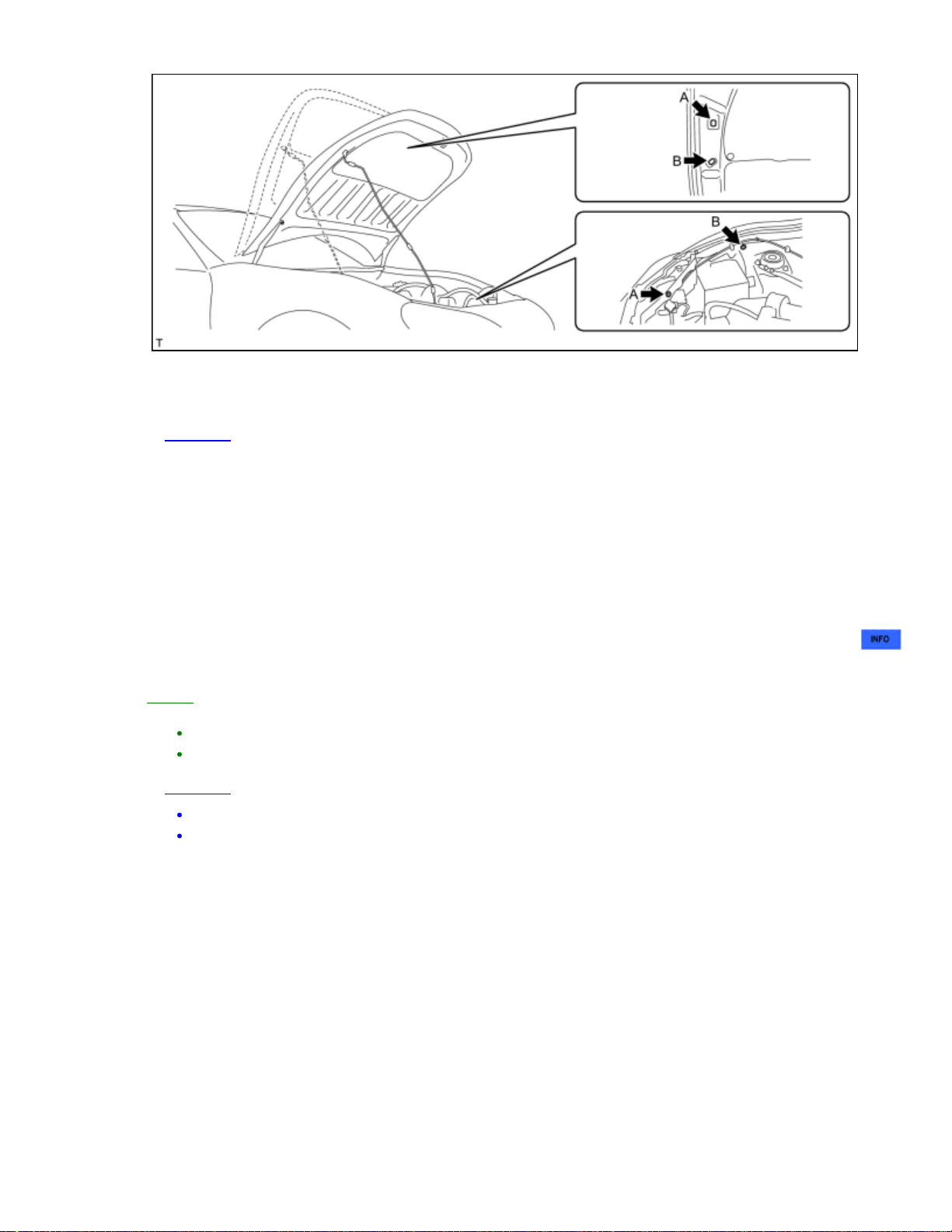
(a) When performing inspections or general maintenance, use the front hood stay in its normal
attachment position.
NOTICE:
When performing inspections or general maintenance, do not remove the front hood stay.
(b) When it is necessary to open the engine hood further to remove the engine, etc., set the front
hood stay in attachment position B, as shown in the illustration.
11. FOR VEHICLES EQUIPPED WITH TRACTION CONTROL (TR(A)C) AND VEHICLE
STABILITY CONTROL (VSC) SYSTEMS
When testing with a 2-wheel drum tester such as a speedometer tester, a combination speedometer and
brake tester, or a chassis dynamometer, or when jacking up the front wheels and turning the wheels,
perform the following procedure to enter inspection mode and disable the TR(A)C and VSC systems
.
HINT:
The vehicle may slip unexpectedly out of the dynamometer because of TR(A)C and VSC operation.
Pressing the VSC OFF switch does not disable TR(A)C and VSC operation completely.
NOTICE:
Make sure that the VSC OFF indicator light will come on.
Secure the vehicle with chains for safety.
12. PRECAUTIONS FOR TOWING REAR WHEEL DRIVE VEHICLES
(a) Use one of the following methods to tow the vehicle.
(b) If the vehicle has trouble with the chassis or drivetrain, use method 1 (flatbed truck).
Page 60

NOTICE:
Do not use any towing method other than those shown above.
(c) If a tow truck is not available, in an emergency the vehicle may be temporarily towed using a cable
or chain secured to the emergency towing eyelet(s).
This should only be attempted on hard surfaced roads for distances of less than 30 km, and at
speeds below 30km/h (19 mph).
A driver must be in the vehicle to steer and operate the brakes. The vehicle's wheels, drivetrain,
axles, steering and brakes must be in good condition.
NOTICE:
If the towing speed or distance exceeds the above limits, or the vehicle is towed in a backward
direction with the wheels on the ground, the drivetrain or vehicle may be damaged.
(1) Emergency towing procedure
1. Turn the ignition switch ON.
2. Depress the brake pedal and move the shift lever to N.
3. Release the parking brake.
4. Release the brake pedal slowly.
NOTICE:
Use extreme caution when towing the vehicle. Avoid sudden starts or erratic driving maneuvers
which place excessive stress on the emergency towing eyelet and the cables or chains.
Do not turn off the ignition switch. Turning off the ignition switch may result in engagement of the
steering lock, resulting in a hazardous situation or accident.
(d) The towing methods shown below are dangerous and can damage the vehicle, so do not use them.
Page 61

(1) Do not tow the vehicle with only 2 wheels on the ground.
CAUTION:
If the vehicle is towed with only the front wheels on the ground, the steering may move,
causing the vehicle to become unstable.
NOTICE:
If the vehicle is towed with only the rear wheels on the ground, the drivetrain may overheat and
be damaged.
(2) Do not use a sling-type towing method either from the front or rear.
NOTICE:
If a sling-type tow truck is used, damage may occur to the vehicle body.
13. FOR VEHICLES EQUIPPED WITH CATALYTIC CONVERTER
CAUTION:
If a large amount of unburned gasoline or gasoline vapors flow into the converter, it may cause
converter overheating and create a fire hazard. To prevent this, observe the following
precautions:
(a) Use only unleaded gasoline.
(b) Avoid performing unnecessary spark tests.
(1) Perform a spark test only when absolutely necessary. Perform this test as rapidly as possible.
(2) While testing, never race the engine unless instructed.
(c) Avoid a prolonged engine compression measurement. Engine compression measurements must be
performed as rapidly as possible.
(d) Do not run the engine when the fuel tank is nearly empty. This may cause the engine to misfire
and create an extra load on the converter.
Page 62

Last Modified: 3-27-2012 6.4 F From: 201203
Model Year: 2013 Model: FR-S Doc ID: RM000000UYY0AOX
Title: INTRODUCTION: REPAIR INSTRUCTION: VEHICLE LIFT AND SUPPORT LOCATIONS (2013 FR-S)
VEHICLE LIFT AND SUPPORT LOCATIONS
1. NOTICE ABOUT VEHICLE CONDITION WHEN RAISING VEHICLE
(a) The vehicle must be unloaded before jacking up or raising the vehicle. Never jack up or raise a
heavily loaded vehicle.
(b) When removing any heavy components like the engine or transaxle, the vehicle center of gravity
will shift. To stabilize the vehicle, place a balance weight in a location that will prevent the vehicle
from rolling or shifting, or place a transmission jack under the appropriate jack position at the
opposite end of the vehicle.
2. NOTICE FOR USING 4 POST LIFT
(a) Follow the safety procedures outlined in the lift's instruction manual.
(b) Do not damage the tires or wheels while driving onto the lift.
(c) Use wheel chocks to secure the vehicle.
3. NOTICE FOR USING JACK AND SAFETY STANDS
(a) Work on a level surface. Use wheel chocks at all times.
(b) Use safety stands with rubber attachments as shown in
the illustration.
Text in Illustration
*1 Rubber Attachment
(c) Set the jack and safety stands exactly under the specified locations on the vehicle.
(d) Do not work on or leave the vehicle supported only by a jack. Be sure to support the vehicle with
safety stands.
(e) When jacking up the vehicle, first release the parking brake and move the shift lever to N.
(f) When jacking up the entire vehicle:
(1) When jacking up the front wheels first, make sure wheel chocks are behind the rear wheels.
(2) When jacking up the rear wheels first, make sure wheel chocks are in front of the front wheels.
(g) When jacking up only the front or rear wheels of the vehicle:
(1) Before jacking up the front wheels, place wheel chocks on both sides of the rear wheels.
(2) Before jacking up the rear wheels, place wheel chocks on both sides of the front wheels.
(h) When lowering a vehicle that only has its front or rear wheels jacked up.
Page 63

(1) Before lowering the front wheels, make sure wheel chocks are in front of the rear wheels.
(2) Before lowering the rear wheels, make sure wheel chocks are behind the front wheels.
4. NOTICE FOR USING A SWING ARM TYPE LIFT
(a) Follow the safety procedures outlined in the lift's instruction manual.
(b) Use swing arms equipped with rubber attachments as shown in the illustration.
(c) Position the vehicle so that its center of gravity is centered on the lift (length of "L" in the
illustration should be as short as possible).
(d) Ensure that the rubber cushions or swing arms do not contact the body cladding or lower
mouldings.
(e) Be sure to lock the swing arms before raising the vehicle (if equipped with arm locks).
(f) Use the lift to raise the vehicle until the tires are off the ground, then stop the lift and shake the
front and rear of the vehicle to make sure that it is stable.
Page 64

5. NOTICE FOR USING PLATE TYPE LIFT
(a) Follow the safety procedures outlined in the lift's instruction manual.
(b) Use plate lift attachments (rubber lifting blocks) on top of the plates.
(c) Be sure to set the vehicle to the specified position described in the following chart and shown in the
following illustration.
Right and left set
position
Front and rear set
position
(d) Ensure that the plate lift or rubber lifting blocks do not contact the body cladding or lower
mouldings.
(e) Use the lift to raise the vehicle until the tires are off the ground, then stop the lift and shake the
front and rear of the vehicle to make sure that it is stable.
Center the vehicle on the lift.
Match the attachments to positions A in the illustration.
Do not use a plate lift with attachments that are unable to reach
positions A in the illustration.
Page 65

Page 66

Last Modified: 3-27-2012 6.4 N From: 201203
(2) Front doors
Model Year: 2013 Model: FR-S Doc ID: RM0000019FS055X
Title: MAINTENANCE: BODY: GENERAL MAINTENANCE (2013 FR-S)
GENERAL MAINTENANCE
1. BODY INSPECTION
(a) Check the body exterior for dents, scratches and rust.
(b) Check the underbody for rust and damage.
If necessary, replace the damaged part or repair the damaged area.
2. REPLACE AIR CONDITIONING FILTER
(a) Remove the air conditioning filter .
(b) Visually inspect the surface of the air conditioning filter.
(c) If the air conditioning filter is contaminated with foreign matter, replace it.
3. ROAD TEST
(a) Check the engine and chassis for abnormal noises.
(b) Check that the vehicle does not wander or pull to one side.
(c) Check that the brakes work properly and do not drag.
(d) Set the parking brake shoes and drums.
4. TIGHTEN BOLTS AND NUTS ON CHASSIS AND BODY
(a) If necessary, tighten the bolts and nuts on the chassis parts listed below.
Front axle and suspension
Drivetrain
Rear axle and suspension
Brake system
Engine mounts
Other chassis parts
(b) If necessary, tighten the bolts and nuts on the body parts listed below.
Seat belt system
Seats
Doors and hood
Body mounts
Fuel tank
Exhaust system
Other body parts
5. FINAL INSPECTION
(a) Check the operation of the body parts.
(1) Hood
Auxiliary catch operates properly.
Hood locks securely when closed.
Page 67

Door locks operate properly.
Doors close properly.
(3) Luggage compartment door
Luggage compartment door opens and closes properly.
(4) Seats
Seats adjust easily and lock securely in any position.
Front seatbacks lock securely in any position.
Fold-down rear seatbacks lock securely.
(5) Be sure to deliver a clean car. Make sure to check the following:
Steering wheel
Shift lever knob
All switches and knobs
Door handles
Seats
Page 68

Last Modified: 3-27-2012 6.4 N From: 201203
Model Year: 2013 Model: FR-S Doc ID: RM000001AQU061X
Title: MAINTENANCE: BRAKE: GENERAL MAINTENANCE (2013 FR-S)
GENERAL MAINTENANCE
1. INSPECT BRAKE LINE PIPES AND HOSES
HINT:
Work in a well- lighted area. Turn the front wheels fully to the
right or left before beginning the inspection.
(a) Using a mirror, check the entire circumference and length
of the brake lines and hoses for:
Damage
Wear
Deformation
Cracks
Bends
Corrosion
Leaks
Twists
(b) Check all the clamps for tightness and connections for
leakage.
(c) Check that the hoses and lines are not near sharp edges,
moving parts or the exhaust system.
(d) Check that the lines are installed properly and pass
through the center of the grommets.
2. INSPECT BRAKE PEDAL
(a) Check the brake pedal for Automatic Transmission, for Manual Transmission).
3. INSPECT PARKING BRAKE
(a) Check the parking brake shoe clearance and parking brake lever travel .
(b) Check the parking brake cables to ensure that they are not deformed or binding.
4. INSPECT BRAKE LININGS AND DRUMS
(a) Check the parking brake linings and drums.
5. INSPECT FRONT BRAKE
(a) Check the front brake pads and discs .
6. INSPECT REAR BRAKE
(a) Check the rear brake pads and discs .
7. INSPECT OR CHANGE BRAKE FLUID
Page 69

(a) Inspect or change the brake fluid .
Page 70

Last Modified: 3-27-2012 6.4 N From: 201203
Model Year: 2013 Model: FR-S Doc ID: RM000001AQV066X
Title: MAINTENANCE: CHASSIS: GENERAL MAINTENANCE (2013 FR-S)
GENERAL MAINTENANCE
1. INSPECT STEERING LINKAGE AND GEAR HOUSING
(a) Check the steering wheel free play .
(b) Check the steering linkage for looseness or damage.
(1) Check that the tie rod ends do not have excessive play.
(2) Check that the dust seals and boots are not damaged.
(3) Check that the boot clamps are not loose.
(4) Check that the steering gear box is not damaged.
(5) Check that the connectors are properly connected to the steering gear box.
2. INSPECT SUSPENSION BALL JOINT AND DUST COVER
(a) Inspect the ball joints for excessive looseness.
(1) Jack up the front of the vehicle and place wooden blocks with a height of 180 to 200 mm (7.09
to 7.87 in.) under the front tires.
(2) Jack up the lower suspension arm until there is about half a load on the front suspension.
(3) Check that the front wheels are pointing straight ahead. Use wheel chocks on all 4 wheels.
(4) Using a lever, pry up the end of the lower arm. Check the amount of play.
Maximum ball joint vertical play:
0 mm (0 in.)
If there is any play, replace the ball joint.
(b) Check the dust cover for damage.
3. INSPECT CLUTCH FLUID LEVEL AND SYSTEM OPERATION
(a) Check the clutch fluid level .
4. INSPECT DRIVE SHAFT BOOTS
(a) Check the drive shaft boots for loose clamps, cracks, grease leaks, kinks or damage.
5. INSPECT AUTOMATIC TRANSMISSION FLUID
(a) Visually check the automatic transmission for fluid leakage. If fluid is leaking, find the cause and
repair it.
(b) Inspect the automatic transmission fluid
.
6. REPLACE AUTOMATIC TRANSMISSION FLUID
(a) Replace the automatic transmission fluid .
7. INSPECT MANUAL TRANSMISSION OIL
(a) Visually check the manual transmission for oil leakage. If fluid is leaking, find the cause and repair
it.
Page 71

(b) Inspect the manual transmission oil .
8. INSPECT REAR DIFFERENTIAL OIL
(a) Visually check the rear differential for oil leakage. If fluid is leaking, find the cause and repair it.
(b) Inspect the rear differential oil
.
9. PERFORM TIRE ROTATION
10. INSPECT FRONT AND REAR SUSPENSION
(a) Check the front and rear suspension.
SUSPENSION TYPE SEE PROCEDURE
Front Suspension
Rear Suspension
Page 72

Last Modified: 3-27-2012 6.4 N From: 201203
Model Year: 2013 Model: FR-S Doc ID: RM000001AQT066X
Title: MAINTENANCE: ENGINE: GENERAL MAINTENANCE (2013 FR-S)
GENERAL MAINTENANCE
HINT:
Perform these procedures after the engine has cooled down.
1. INSPECT DRIVE BELT
(a) Inspect the drive belt .
2. INSPECT ENGINE OIL
(a) Inspect the engine oil .
3. REPLACE ENGINE OIL AND OIL FILTER
(a) Replace the engine oil and oil filter .
4. INSPECT ENGINE COOLANT
(a) Inspect the engine coolant .
5. REPLACE ENGINE COOLANT
(a) Replace the engine coolant .
6. REPLACE SPARK PLUGS
(a) Replace the spark plugs .
7. REPLACE FUEL FILTER
(a) Replace the fuel filter .
8. INSPECT BATTERY
(a) Check the battery .
9. INSPECT AIR CLEANER FILTER ELEMENT
(a) Remove the air cleaner filter element.
(b) Check that the air cleaner filter element is not excessively dirty. If the air cleaner filter element is
excessively dirty, replace the air cleaner filter element.
(c) Clean the air cleaner filter element with compressed air.
(d) Reinstall the air cleaner filter element.
10. INSPECT EXHAUST PIPES AND MOUNTINGS
(a) Visually check the pipes, hangers and connections for severe corrosion, leaks or damage.
11. INSPECT FUEL TANK CAP ASSEMBLY
(a) Inspect the fuel tank cap gasket .
12. INSPECT FUEL LINES, CONNECTIONS, FUEL TANK VAPOR VENT SYSTEM HOSES AND
FUEL TANK BANDS
Page 73

(a) Visually check the fuel lines and hoses for cracks, leakage, loose connections, or deformation.
(b) Check for tank band looseness or deformation.
Page 74

Last Modified: 3-27-2012 6.4 N From: 201203
Model Year: 2013 Model: FR-S Doc ID: RM000000UZE09JX
Title: MAINTENANCE: INSIDE VEHICLE: GENERAL MAINTENANCE (2013 FR-S)
GENERAL MAINTENANCE
These are maintenance and inspection items that are considered to be the owner's responsibility.
The owner can do them or they can have them done at a service center.
These items include those that should be checked on a daily basis, those that in most cases
do not require special tools, and those that are considered to be reasonable for the owner to
do.
General maintenance items and procedures are as follows:
1. GENERAL NOTES
Maintenance requirements vary depending on the country.
Check the maintenance schedule in the owner's manual supplement.
Determine the appropriate time to service the vehicle using either miles driven or time
(months) elapsed, whichever reaches the specification first.
Maintain similar intervals between periodic maintenance unless noted.
Failing to check each vehicle part could lead to poor engine performance and increase exhaust
emissions.
2. LIGHTS
(a) Check that the headlights, stop lights, taillights, turn signal lights, and other lights illuminate or
blink properly. Also, check if they have enough brightness.
(b) Check that the headlights are aimed properly.
3. WARNING LIGHTS AND BUZZERS
(a) Check that all the warning lights and buzzers are working.
4. HORNS
(a) Check if the horns are working correctly.
5. WINDSHIELD GLASS
(a) Check for scratches, pits or abrasions.
6. WINDSHIELD WIPER AND WASHER
(a) Check that the washers are aimed properly. Also, check that the washer fluid hits the center of the
operating range of each wiper on the windshield.
(b) Check if the wipers streak. Replace them if necessary.
7. WINDSHIELD DEFROSTER
(a) When the air conditioning is on the defroster setting, check that air comes out of the defroster
outlets.
8. REAR VIEW MIRROR
(a) Check that the rear view mirror is securely mounted.
Page 75

9. SUN VISORS
(a) Check that the sun visors move freely and are securely mounted.
10. STEERING WHEEL
(a) Check that the steering wheel has the proper amount of free play. Also check for steering difficulty
and unusual noises
.
11. SEATS
(a) Check that the seat adjusters, seatback recliner and other seat controls operate smoothly.
(b) Check that all the latches lock securely in all positions.
(c) Check that the locks hold securely in all positions.
(d) Check that the headrests move up and down smoothly and that the locks hold securely in all
latched positions.
(e) When the rear seatbacks are folded down, check that the latches lock securely.
12. SEAT BELTS
(a) Check that the seat belt components, such as the buckles, retractors and anchors, operate properly
and smoothly.
(b) Check that the belt webbing is not cut, frayed, worn or damaged.
13. ACCELERATOR PEDAL
(a) Check that the pedal operates smoothly. Check that the pedal does not have uneven resistance or
stick in certain positions.
14. BRAKE PEDAL
(a) Check that the brake pedal operates smoothly.
(b) Check that the pedal has the proper reserve distance and free play
Transmission,
(c) Start the engine and check the brake booster function.
(d) Start the engine and check the brake system indicator.
for Manual Transmission).
for Automatic
15. BRAKES
(a) In a safe place, check that the vehicle does not pull or lead to the side when applying the brakes.
16. PARKING BRAKE
(a) Check that the parking brake lever has the proper amount of travel .
(b) On a slight grade, check that the parking brake alone can hold the vehicle in place.
17. AUTOMATIC TRANSMISSION "PARK" MECHANISM
(a) Check the shift lever for proper and smooth operation.
(b) When the shift lever is in P and all brakes are released in an area that has a slight grade, check
that the vehicle is stable.
18. FLOOR MATS
(a) Check that the correct floor mats are used, and that they are properly installed.
Page 76

Last Modified: 3-27-2012 6.4 N From: 201203
Model Year: 2013 Model: FR-S Doc ID: RM000000UZD08YX
Title: MAINTENANCE: OUTSIDE VEHICLE: GENERAL MAINTENANCE (2013 FR-S)
GENERAL MAINTENANCE
These are maintenance and inspection items that are considered to be the owner's responsibility.
The owner can do them or they can have them done at a service center.
These items include those that should be checked on a daily basis, those that in most cases
do not require special tools, and those that are considered to be reasonable for the owner to
do.
General maintenance items and procedures are as follows:
1. GENERAL NOTES
Maintenance requirements vary depending on the country.
Check the maintenance schedule in the owner's manual supplement.
Following the maintenance schedule is mandatory.
Determine the appropriate time to service the vehicle using either miles driven or time
(months) elapsed, whichever reaches the specification first.
Failing to check each vehicle part could lead to poor engine performance and increase exhaust
emissions.
2. TIRES
(a) Check the tire inflation pressure with a gauge. Make adjustments if necessary.
(b) Check the surfaces of the tires for cuts, damage or excessive wear.
3. WHEEL NUTS
(a) Check for nuts that are loose or missing. Tighten them if necessary.
4. TIRE ROTATION
(a) Check the maintenance schedule in the owner's manual supplement.
5. WINDSHIELD WIPER BLADES
(a) Check the blades for wear or cracks whenever they are unable to wipe the windshield clean.
Replace them if necessary.
6. FLUID LEAKS
(a) Check under the vehicle for leaking fuel, oil, water and other fluids.
NOTICE:
If you smell fuel or notice any leaks, locate the cause and correct it.
7. DOORS AND ENGINE HOOD
(a) Check that all of the doors and the hood operate smoothly, and that all the latches lock securely.
(b) When the primary latch is released, check that the engine hood secondary latch prevents the hood
from opening.
Page 77

Last Modified: 3-27-2012 6.4 N From: 201203
engine turned off.
Model Year: 2013 Model: FR-S Doc ID: RM000000UZF091X
Title: MAINTENANCE: UNDER HOOD: GENERAL MAINTENANCE (2013 FR-S)
GENERAL MAINTENANCE
1. GENERAL NOTES
Maintenance requirements vary depending on the country.
Check the maintenance schedule in the owner's manual supplement.
Following the maintenance schedule is mandatory.
Determine the appropriate time to service the vehicle using either miles driven or time
(months) elapsed, whichever reaches the specification first.
Maintain similar intervals between periodic maintenance unless noted.
Failing to check each maintenance item could lead to poor engine performance and increase
exhaust emissions.
2. WINDSHIELD WASHER FLUID
(a) Check that there is sufficient fluid in the tank.
3. ENGINE COOLANT LEVEL
(a) Check that the coolant level is between the "FULL" and "LOW" lines on the see-through reservoir.
4. RADIATOR AND HOSES
(a) Check that the front of the radiator is clean and not blocked by leaves, dirt and bugs.
(b) Check the radiator and hoses for:
Damage
Cracks
Kinks
Corrosion
Rot
Clogging
Leaks
5. BATTERY ELECTROLYTE LEVEL
(a) Check that the electrolyte level of all the battery cells is between the upper and lower level lines on
the case.
HINT:
If the electrolyte level is difficult to see, lightly shake the vehicle.
6. BRAKE FLUID LEVEL
7. ENGINE DRIVE BELT
8. ENGINE OIL LEVEL
(a) Check that the brake fluid level is near the upper level line on the see-through reservoirs.
(a) Check the drive belt for fraying, cracks, wear or oil.
(a) Check that the engine oil level is between the full level and low level marks on the dipstick with the
Page 78

9. EXHAUST SYSTEM
(a) Visually inspect for severe corrosion, cracks, holes or loose supports.
HINT:
If any change in the sound of the exhaust or smell of the exhaust fumes is noticed, inspect and repair
the exhaust system.
Page 79

Last Modified: 3-27-2012 6.4 B From: 201203
Model Year: 2013 Model: FR-S Doc ID: RM000003KES00HX
Title: PREPARATION: ALIGNMENT / HANDLING DIAGNOSIS: EQUIPMENT (2013 FR-S)
EQUIPMENT
Torque wrench Vernier caliper Alignment tester Toe-in gauge Camber-caster-kingpin gauge -
Page 80

Last Modified: 3-27-2012 6.4 B From: 201203
Model Year: 2013 Model: FR-S Doc ID: RM0000020C700RX
Title: PREPARATION: AUDIO / VIDEO: EQUIPMENT (2013 FR-S)
EQUIPMENT
Torque wrench -
Page 81

Last Modified: 3-27-2012 6.4 B From: 201203
Model Year: 2013 Model: FR-S Doc ID: RM0000020FO00IX
Title: PREPARATION: AUDIO / VIDEO: RECOMMENDED TOOLS (2013 FR-S)
RECOMMENDED TOOLS
09080-1C110 Toyota Electrical Tester Set -
09080-2C100 Test Lead Set -
Page 82

Last Modified: 3-27-2012 6.4 B From: 201203
Model Year: 2013 Model: FR-S Doc ID: RM000002H7Q010X
Title: PREPARATION: AXLE AND DIFFERENTIAL: EQUIPMENT (2013 FR-S)
EQUIPMENT
Axle
Torque wrench Dial indicator with magnetic base Non-residue solvent -
Differential
Torque wrench Micrometer Dial indicator with magnetic base Non-residue solvent Prussian blue MP grease -
Page 83

Last Modified: 3-27-2012 6.4 B From: 201203
Model Year: 2013 Model: FR-S Doc ID: RM000002H7R00ZX
Title: PREPARATION: AXLE AND DIFFERENTIAL: LUBRICANT (2013 FR-S)
LUBRICANT
Differential
ITEM CAPACITY OIL GRADE
Rear
differential
oil
(except
LSD)
Rear
differential
oil
(for LSD)
1.10 to 1.20 liters (1.17 to 1.27 US qts,
0.97 to 1.05 Imp. qts)
1.10 to 1.20 liters (1.17 to 1.27 US qts,
0.97 to 1.05 Imp. qts)
Toyota genuine differential gear oil LT 75W85 GL-5 or equivalent
Toyota genuine differential gear oil LX 75W85 GL-5 or equivalent
Page 84

Last Modified: 3-27-2012 6.4 B From: 201203
Model Year: 2013 Model: FR-S Doc ID: RM000002ZWC00VX
Title: PREPARATION: AXLE AND DIFFERENTIAL: RECOMMENDED TOOLS (2013 FR-S)
RECOMMENDED TOOLS
09010-3C110 Set, Hexagon Socket Wrench -
(09013-6C130) Socket Hexagon
10mm
09051-1C110 Plastic Hammer -
09051-1C300 Chisel -
09072-1C200 Vernier Calipers
150mm
09905-00013 Snap Ring Pliers -
-
-
Page 85

Last Modified: 3-27-2012 6.4 B From: 201203
Model Year: 2013 Model: FR-S Doc ID: RM000002H7P00ZX
Title: PREPARATION: AXLE AND DIFFERENTIAL: SSM (2013 FR-S)
SSM
Toyota Genuine Seal Packing 1281, Three Bond 1281 or equivalent -
Page 86

Last Modified: 3-27-2012 6.4 B From: 201203
Model Year: 2013 Model: FR-S Doc ID: RM000003KC800HX
Title: PREPARATION: AXLE AND DIFFERENTIAL: SST (2013 FR-S)
SST
09213-70011 Crankshaft Pulley Holding Tool -
09308-00010 Oil Seal Puller -
09330-00021 Companion Flange Holding Tool -
09504-22011 Differential Side Bearing
Replacer
09506-30012 Differential Drive Pinion Rear
Bearing Cone Replacer
09520-01010 Drive Shaft Remover Attachment -
09520-24010 Differential Side Gear Shaft
Puller
-
-
-
(09520-32040) Shocker Set -
09554-22010 Differential Oil Seal Replacer -
Page 87

09556-22010 Drive Pinion Front Bearing
Remover
09570-18010 Rear Differential Mount Cushion
Remover and Replacer
(09571-01010) Remover -
(09571-01020) Base No.1 -
(09571-01030) Base No.2 -
-
-
(09571-01040) Replacer -
(09571-01050) Sleeve -
(09571-01060) Ring -
(09571-01070) Nut -
(09571-01080) Bearing -
Page 88

(09571-01090) Shaft -
09570-18020 Rear Differential Mount Cushion
Remover and Replacer
(09571-01100) Remover -
(09571-01110) Base No.1 -
(09571-01120) Base No.2 -
(09571-01130) Replacer -
-
(09571-01140) Sleeve -
(09571-01150) Plate -
(09571-01160) Nut -
(09571-01170) Bearing -
(09571-01180) Bolt -
Page 89

(09571-01190) Shaft -
09636-20010 Upper Ball Joint Dust Cover
Replacer
09710-18030 Rear Suspension Bush Tool Set -
09710-30012 Rear Suspension Bush Tool
Set
(09710-04081) Base -
09716-18010 Rear Suspension Bush
Remover and Replacer
-
-
-
09922-10010 Variable Open Wrench -
09930-00010 Drive Shaft Nut Chisel -
09950-00020 Bearing Remover -
09950-30012 Puller A Set -
(09951-03010) Upper Plate -
Page 90

(09953-03010) Center Bolt -
(09954-03010) Arm -
(09955-03030) Lower Plate 130 -
(09956-03030) Adaptor 20 -
09950-40011 Puller B Set -
(09951-04020) Hanger 200 -
(09952-04010) Slide Arm -
(09953-04030) Center Bolt 200 -
(09954-04010) Arm 25 -
(09955-04061) Claw No. 6 -
Page 91

(09957-04010) Attachment -
(09958-04011) Holder -
09950-60010 Replacer Set -
(09951-00350) Replacer 35 -
(09951-00380) Replacer 38 -
(09951-00430) Replacer 43 -
(09951-00480) Replacer 48 -
(09951-00580) Replacer 58 -
(09951-00590) Replacer 59 -
(09952-06010) Adapter -
Page 92

09950-60020 Replacer Set No. 2 -
(09951-00720) Replacer 72 -
(09951-00890) Replacer 89 -
09950-70010 Handle Set -
(09951-00410) Replacer 41 -
(09951-00620) Replacer 62 -
(09951-07100) Handle 100 -
(09951-07200) Handle 200 -
(09952-06010) Adapter -
09960-20010 Ball Joint Puller Set -
Page 93

(09961-02010) Assy
Ball Joint Puller
(09961-02060) Spacer B -
-
Page 94

Last Modified: 3-27-2012 6.4 B From: 201203
Model Year: 2013 Model: FR-S Doc ID: RM0000039YI07PX
Title: PREPARATION: BRAKE (FRONT): EQUIPMENT (2013 FR-S)
EQUIPMENT
Vinyl tape Ruler Dial indicator with magnetic base Micrometer Torque wrench Wooden Plate -
Page 95

Last Modified: 3-27-2012 6.4 B From: 201203
Model Year: 2013 Model: FR-S Doc ID: RM0000039YJ04TX
Title: PREPARATION: BRAKE (FRONT): LUBRICANT (2013 FR-S)
LUBRICANT
ITEM CAPACITY CLASSIFICATION
Brake fluid - SAE J1703 or FMVSS No. 116 DOT3
Page 96

Last Modified: 3-27-2012 6.4 B From: 201203
Model Year: 2013 Model: FR-S Doc ID: RM0000039YH07OX
Title: PREPARATION: BRAKE (FRONT): RECOMMENDED TOOLS (2013 FR-S)
RECOMMENDED TOOLS
09017-1C100 Union Nut Wrench
10 mm
-
Page 97

Last Modified: 3-27-2012 6.4 B From: 201203
Model Year: 2013 Model: FR-S Doc ID: RM0000039YI07QX
Title: PREPARATION: BRAKE (REAR): EQUIPMENT (2013 FR-S)
EQUIPMENT
Vinyl tape Ruler Dial indicator with magnetic base Micrometer Wooden block Torque wrench -
Page 98

Last Modified: 3-27-2012 6.4 B From: 201203
Model Year: 2013 Model: FR-S Doc ID: RM0000039YJ04UX
Title: PREPARATION: BRAKE (REAR): LUBRICANT (2013 FR-S)
LUBRICANT
ITEM CAPACITY CLASSIFICATION
Brake fluid - SAE J1703 or FMVSS No. 116 DOT3
Page 99

Last Modified: 3-27-2012 6.4 B From: 201203
Model Year: 2013 Model: FR-S Doc ID: RM0000039YH07PX
Title: PREPARATION: BRAKE (REAR): RECOMMENDED TOOLS (2013 FR-S)
RECOMMENDED TOOLS
09017-1C100 Union Nut Wrench
10 mm
-
Page 100

Last Modified: 3-27-2012 6.4 B From: 201203
Model Year: 2013 Model: FR-S Doc ID: RM0000043ET003X
Title: PREPARATION: BRAKE CONTROL / DYNAMIC CONTROL SYSTEMS: EQUIPMENT (2013 FR-S)
EQUIPMENT
Torque wrench -
 Loading...