

Page 1
C92542
05–297
–DIAGNOSTICS ABS WITH EBD SYSTEM (April, 2003)
057U9–04
PRE–CHECK
1. DIAGNOSIS SYSTEM
(a) Release the parking brake lever.
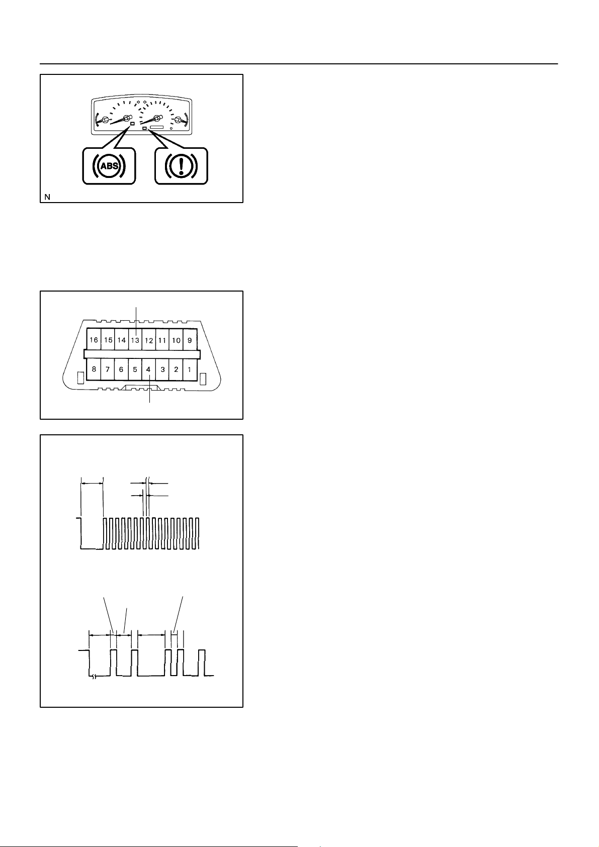
(b) Check the warning lights.
When the ignition switch is turned ON, check that the ABS
warning light and brake warning light goes on for 3 sec.
HINT:
! When the parking brake is applied or the level of the brake
fluid is low, the brake warning light is lit.
! If the indicator check result is not normal, proceed to trou-
bleshooting for the ABS warning light circuit (See page
05–332 or 05–335) or brake warning light circuit (See
page 05–338).
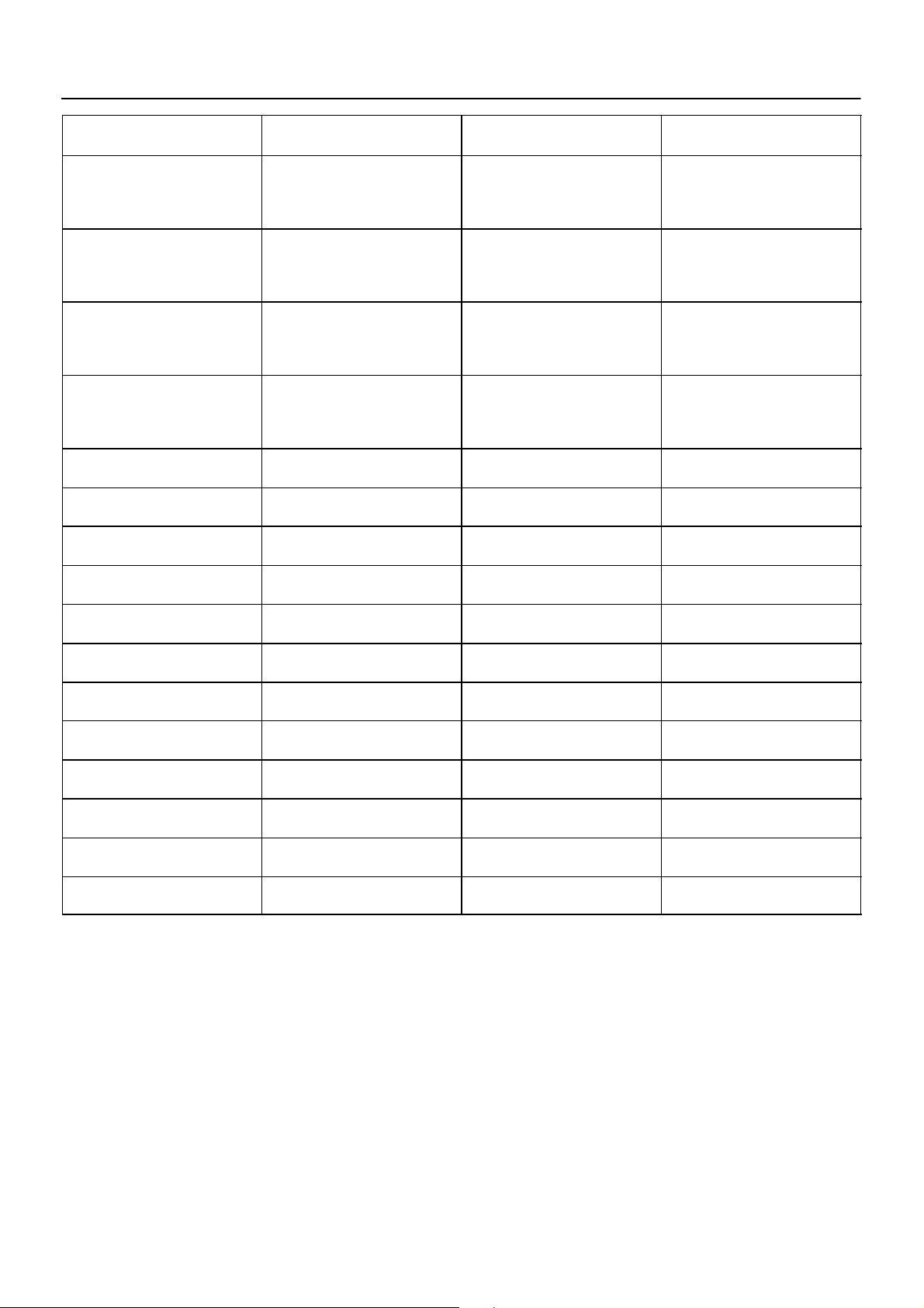
ON
OFF
ON
OFF
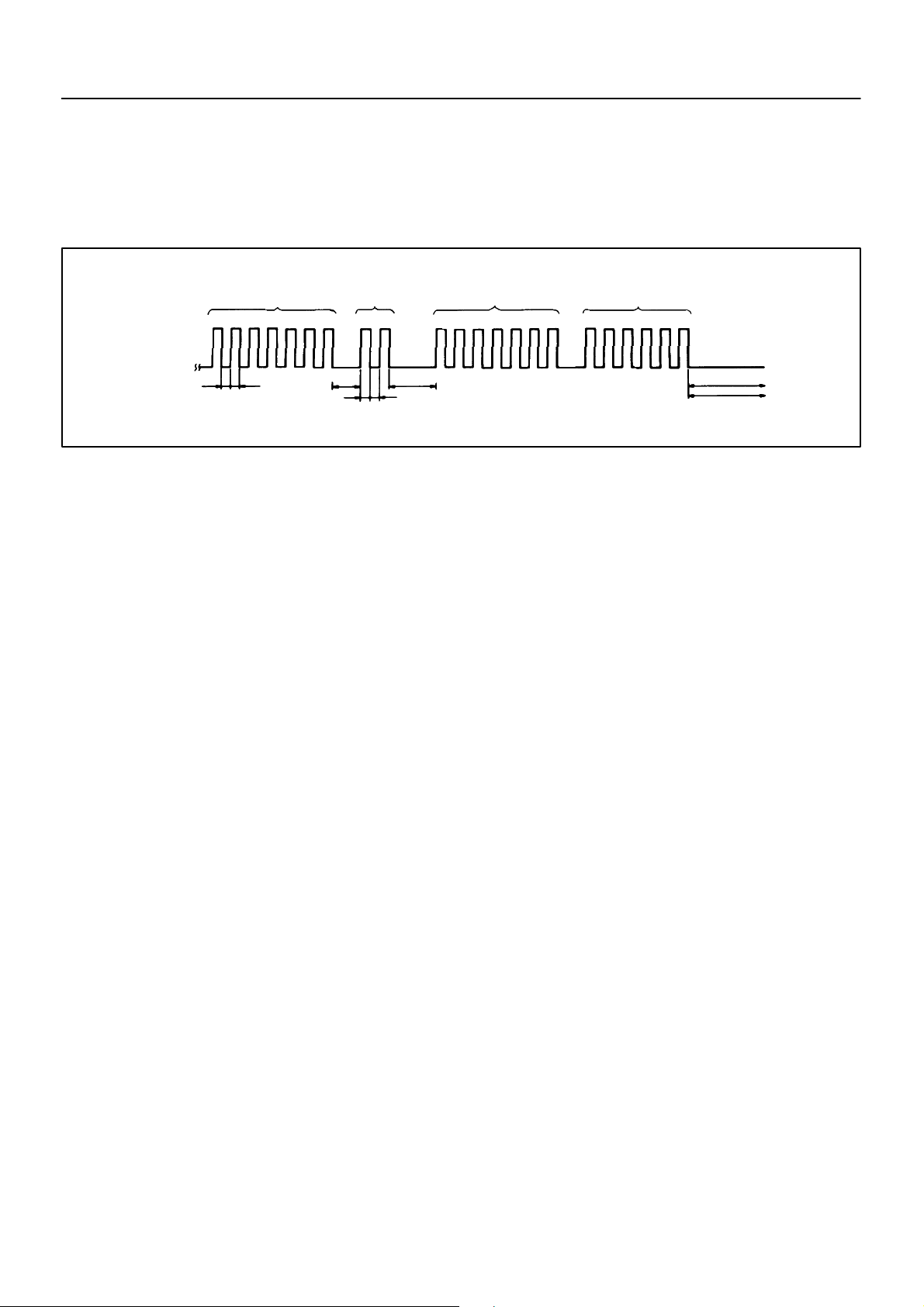
Normal Code
2 sec.
Code 11 and 21
0.5 sec.
4 sec.
Code 11
Tc
CG
1.5 sec.
2.5 sec.
0.25 sec.
0.25 sec.
0.5 sec.
Code 21
C52361
R01346
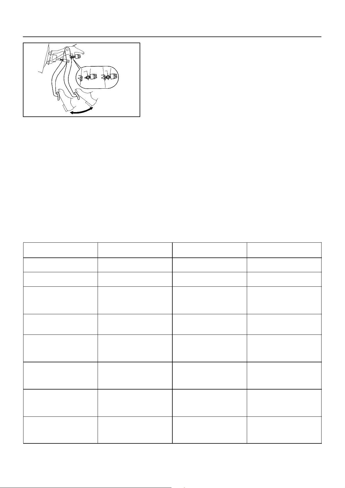
(c) In case of not using hand–held tester:
Check the DTC.
(1) Using SST, it connects terminal Tc and CG of DLC3.
SST 09843–18040
(2) Turn the ignition switch to ON.
(3) Read the DTC from the ABS warning light on the
combination meter.
HINT:
! If not code appears, inspect the diagnostic circuit or ABS
warning light circuit (See page 05–332 or 05–335 ).
! As an example, the blinking patterns for normal code and
codes 11 and 21 are shown on the left.
(4) Codes are explained in the code table on page
05–303.
If 2 or more malfunctions are indicated at the same time, the
lowest numbered DTC will be displayed 1st.
(5) After completing the check, remove the SST from
the DLC3.
SST 09843–18040
(d) In case of using hand–held tester:
Check the DTC.
(1) Read the DTC by following the prompts on the tes-
ter screen.
HINT:
Please refer to the hand–held tester operator’s manual for further details.
(e) In case of not using hand–held tester:
Clear DTC.
(1) Using SST, it connects the terminal Tc and CG of the
DLC3.
SST 09843–18040
(2) Turn the ignition switch to ON.
2004 COROLLA (RM1037U)
462Author!: Date!:
Page 2
05–298
–DIAGNOSTICS ABS WITH EBD SYSTEM (April, 2003)
(3) Clear DTC stored in ECU by depressing the brake
pedal 8 or more times whitin 5 sec.
(4) Check that the ABS warning light shows the normal
code.
(5) Remove the SST from the DLC3.
SST 09843–18040
HINT:
Disconnect the battey cable during repairs will not erase the
BR3890
DTC in the ECU.
(f) In case of using hand–held tester:
Clear the DTC.
(1) Turn the ignition switch to ON.
(2) Operate the hand–held tester to erase the codes.
HINT:
Please refer to the hand–held tester operator’s manual for further details.
2. DATA LIST
HINT:
According to the DATA LIST displayed by the Hand–held tester, you can read the value of the switch, sensor,
actuator and so on without parts removal. Reading the DATA LIST as a first step of troubleshooting is one
of the method to shorten the labor time.
(a) Connect the Hand–held tester to the DLC3.
(b) Turn the ignition switch to ON.
(c) According to the display on tester, read the ”DATA LIST”.
Item
ABS MOT RELAY
SOL RELAY
STOP LIGHT SW
PKB SW
ABS OPERT FR
ABS OPERT FL
ABS OPERT RR
ABS OPERT RL
Measurement Item /
Range (Display)
ABS motor relay / ON or
OFF
Solenoid relay / ON or
OFF
Stop light switch / ON or
OFF
Parking brake switch / ON
or OFF
ABS operation (FR) / BEFORE or OPERATE
ABS operation (FL) / BEFORE or OPERATE
ABS operation (RR) / BEFORE or OPERATE
ABS operation (RL) / BEFORE or OPERATE
Normal Condition Diagnostic Note
ON : Brake pedal depressed
OFF : Brake pedal released
ON : Parking brake applied
OFF : Parking brake released
BEFORE : No ABS operation (FR)
OPERATE : During ABS
operation (FR)
BEFORE : No ABS operation (FL)
OPERATE : During ABS
operation (FL)
BEFORE : No ABS operation (RR)
OPERATE : During ABS
operation (RR)
BEFORE : No ABS operation (RL)
OPERATE : During ABS
operation (RL)
2004 COROLLA (RM1037U)
463Author!: Date!:
Page 3
–DIAGNOSTICS ABS WITH EBD SYSTEM (April, 2003)
05–299
Item Diagnostic NoteNormal Condition
WHEEL SPD FR
WHEEL SPD FL
WHEEL SPD RR
WHEEL SPD RL
IG VOLTAGE
SFRR
SFRH
SFLR
SFLH
SRRR
SRRH
SRLR
SRLH
AIR BLD SUPPORT
TEST MODE
#CODES
Measurement Item /
Range (Display)
Wheel speed sensor (FR)
reading / min.: 0 km/h (0
MPH, max.: 326 km/h (202
MPH)
Wheel speed sensor (FL)
reading / min.: 0 km/h (0
MPH, max.: 326 km/h (202
MPH)
Wheel speed sensor (RR)
reading / min.: 0 km/h (0
MPH, max.: 326 km/h (202
MPH)
Wheel speed sensor (RL)
reading / min.: 0 km/h (0
MPH, max.: 326 km/h (202
MPH)
ECU power supply voltage
/ NORMAL or TOO LOW
ABS solenoid (SFRR) ON /
OFF
ABS solenoid (SFRH) ON /
OFF
ABS solenoid (SFLR) ON /
OFF
ABS solenoid (SFLH) ON /
OFF
ABS solenoid (SRRR) ON /
OFF
ABS solenoid (SRRH) ON
/ OFF
ABS solenoid (SRLR) ON /
OFF
ABS solenoid (SRLH) ON /
OFF
Air bleed support /
SUPPORT or NOT SUP
Test mode / NORMAL or
TEST
Number of DTC recorded /
min.: 0, max.: 255
Actual wheel speed
Actual wheel speed
Actual wheel speed
Actual wheel speed
NORMAL : 9.5 V or over
TOO LOW : Below 9.5 V
Supported
NORMAL : Normal mode
TEST : During test mode
Min.: 0, max.: 19
Speed indicated on
speedometer
Speed indicated on
speedometer
Speed indicated on
speedometer
Speed indicated on
speedometer
3. ACTIVE TEST
HINT:
Performing the ACTIVE TEST using the Hand–held tester allows the relay, actuator and so on to operate
without parts removal. Performing the ACTIVE TEST as a first step of troubleshooting is one of the methods
to shorten the labor time.
It is possible to display the DATA LIST during the ACTIVE TEST.
(a) Connect the Hand–held tester to the DLC3.
(b) Turn the ignition switch to ON.
(c) According to the display on tester, perform the ”ACTIVE TEST”.
2004 COROLLA (RM1037U)
464Author!: Date!:
Page 4

05–300
–DIAGNOSTICS ABS WITH EBD SYSTEM (April, 2003)
Item Vehicle Condition / Test Details Diagnostic Note
SFRR Turns ABS solenoid (SFRR) ON / OFF
SFRH Turns ABS solenoid (SFRH) ON / OFF
SFLR Turns ABS solenoid (SFLR) ON / OFF
SFLH Turns ABS solenoid (SFLH) ON / OFF
SRRR Turns ABS solenoid (SRRR) ON / OFF
SRRH Turns ABS solenoid (SRRH) ON / OFF
SRLR Turns ABS solenoid (SRLR) ON / OFF
SRLH Turns ABS solenoid (SRLH) ON / OFF
SFRR & SFRH Turns ABS solenoid SFRR & SFRH ON / OFF
SFLR & SFLH Turns ABS solenoid SFLR & SFLH ON / OFF
SRRH & SRRR Turns ABS solenoid SRH & SRR ON / OFF
SRLR & SRLH Turns ABS solenoid SRLR & SRLH ON / OFF
SFRH & SFLH Turns ABS solenoid SFRH & SFLH ON / OFF
SOL RELAY Turns ABS solenoid relay ON / OFF
ABS MOT RELAY Turns ABS motor relay ON / OFF
ABS WARN LIGHT Turns ABS warning light ON / OFF
BRAKE WRN LIGHT Turns BRAKE warning light ON / OFF
Operation of solenoid
(clicking sound) can be
heard
Operation of solenoid
(clicking sound) can be
heard
Operation of solenoid
(clicking sound) can be
heard
Operation of solenoid
(clicking sound) can be
heard
Operation of solenoid
(clicking sound) can be
heard
Operation of solenoid
(clicking sound) can be
heard
Operation of solenoid
(clicking sound) can be
heard
Operation of solenoid
(clicking sound) can be
heard
Operation of solenoid
(clicking sound) can be
heard
Operation of solenoid
(clicking sound) can be
heard
Operation of solenoid
(clicking sound) can be
heard
Operation of solenoid
(clicking sound) can be
heard
Operation of solenoid
(clicking sound) can be
heard
Operation of solenoid
(clicking sound) can be
heard
Operation of motor can be
heard
Observe combination meter
Observe combination meter
4. FREEZE FRAME DATA
(a) The vehicle (sensor) status memorized during ABS operation or at the time of error code detection can
be displayed using the hand–held tester.
(b) Only one record of freeze frame data is stored and the freeze frame data generated during ABS opera-
tion are constantly updated. Also, the number of the ignition switch’s ”ON” after the freeze frame data
is stored can be memorized up to 31 and it can be displayed.
HINT:
If the ignition switch ”ON” operation exceeds 31 times, ”31” appears on the display.
2004 COROLLA (RM1037U)
465Author!: Date!:
Page 5
05–301
–DIAGNOSTICS ABS WITH EBD SYSTEM (April, 2003)
(c) If the diagnosis code abnormality occurs, the freeze frame data at the occurrence of the abnormality
is stored but the ABS actuation data is deleted.
Hand–held tester display Measurement Item Reference Value*
VEHICLE SPD Vehicle speed Speed indication of a meter
STOP LIGHT SW Stop light switch signal Stop light switch ON: ON, OFF: OFF
# IG ON
SYSTEM Operate system ABS operate: ABS
Numbers of operations of ignition switch ON after
memorizing freeze frame data
0 – 31
*: If no conditions are specifically stated for ”Idling”, it means the shift lever is at N or P position, the A/C switch
is OFF and all accessory switches are OFF.
5. SPEED SENSOR SIGNAL CHECK
HINT:
If the ignition switch is turned from ON to ACC or LOCK during
test mode, DTC will be erased.
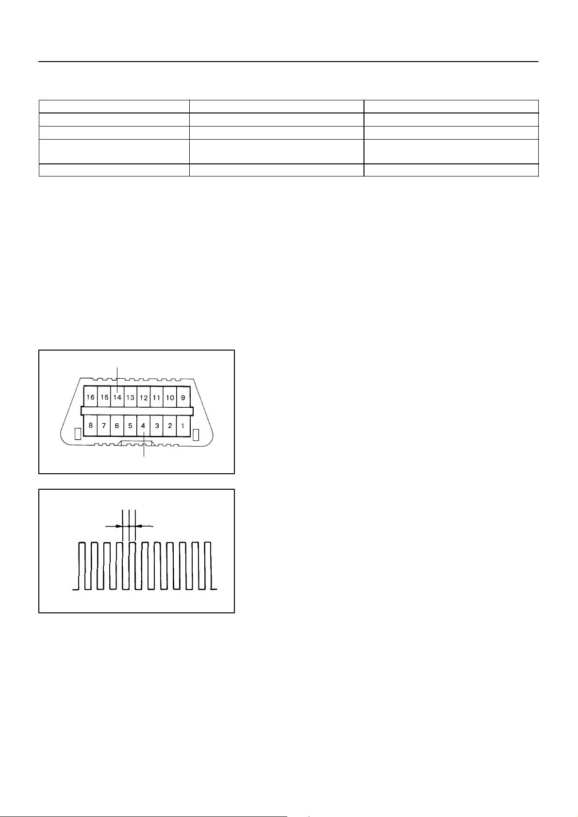
(a) In case of not using hand–held tester:
Check the speed sensor signal.
(1) Turn the ignition switch to ON.
ON
OFF
0.13 sec.
Ts
CG
0.13 sec.
C52361
BR3904
(2) Using SST, it connects the terminal Ts and CG of
DLC3.
SST 09843–18040
(3) Start the engine.
(4) Check that the ABS warning light blinks.
HINT:
If the ABS warning light does not blink, inspect the ABS warning
light circuit and Ts circuit (See page 05–332 or 05–335).
(5) Drive the vehicle straight forward at the speed of 45
km/h (28 mph) or over for several seconds and
check that the ABS warning light comes off.
HINT:
The sensor check may not be completed if the wheels spin or
the steering wheels steered during check.
(6) Stop the vehicle.
(7) Using SST, it connects the terminal Tc and CG of the
DLC3.
SST 09843–18040
(8) Read the number of blinks of the ABS warning light.
2004 COROLLA (RM1037U)
466Author!: Date!:
Page 6
05–302
–DIAGNOSTICS ABS WITH EBD SYSTEM (April, 2003)
HINT:
! See the list of DTC shown on the 05–303.
! If every sensor is normal, a normal code is output (A cycle
of 0.25 sec. ON and 0.25 sec. OFF is repeated).
! If 2 or more malfunctions are indicated at the same time,
the lowest numbered code will be displayed.
Malfunction Code (Example Code 72, 76)
72 7 6
ON
OFF
0.5 sec.
0.5 sec.
1.5 sec.
0.5 sec. 0.5 sec.
2.5 sec.
(b) In case of using hand–held tester:
HINT:
Please refer to the hand–held tester operator’s manual for further details.
4 sec.
Repeat
BR3893
(9) After performing the check, turn the ignition switch
to OFF, and remove the SST from the DLC3.
SST 09843–18040
Check the speed sensor signal.
(1) Do step (3) to (6) on the previous page.
(2) Read the DTC by following the prompts on the tes-
ter screen.
2004 COROLLA (RM1037U)
467Author!: Date!:
Page 7
–HEATER & AIR CONDITIONER W/RECEIVER CONDENSER ASSY
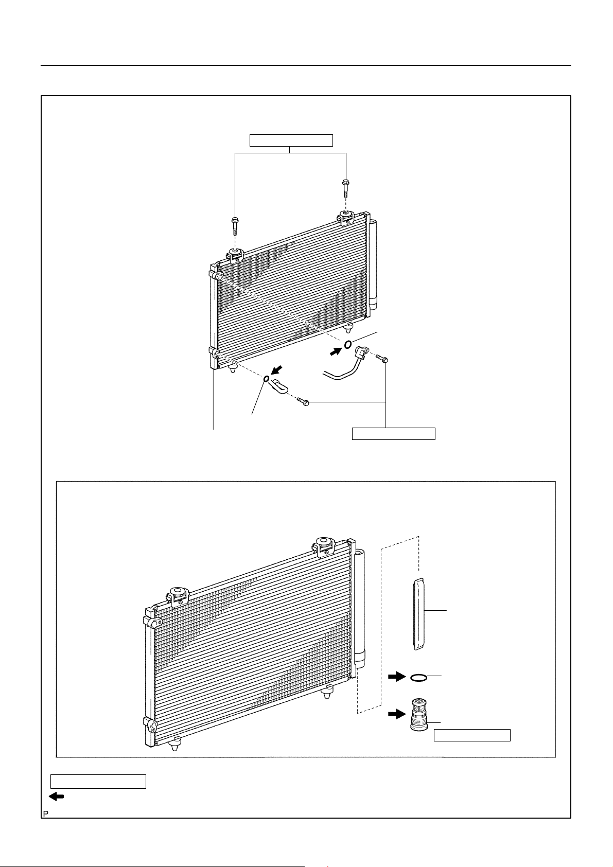
OVERHAUL
HINT:
COMPONENTS: See page 55–40
1. DISCHARGE REFRIGERANT FROM REFRIGERATION SYSTEM (See page 55–11)
SST 07110–58060 (07117–58080, 07117–58090, 07117–78050, 07117–88060, 07117–88070,
07117–88080)
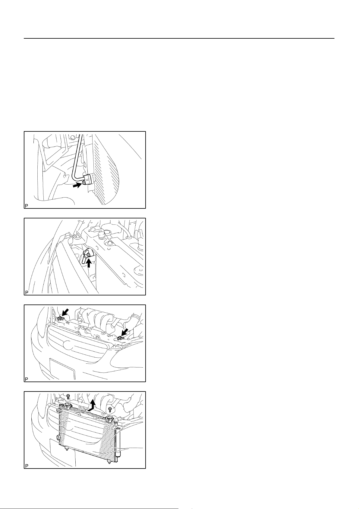
2. DISCONNECT COOLER REFRIGERANT LIQUID PIPE
A
(a) Remove the bolt and disconnect the cooler refrigerant liq-
uid pipe A from the w/receiver condenser assy.
(b) Remove the O–ring from the cooler refrigerant liquid pipe
A.
NOTICE:
Seal the opening of the disconnected parts using vinyl tape
I31967
to prevent moisture and foreign matter from entering.
55–41
550IY–01
I32450
I32451
3. DISCONNECT DISCHARGE HOSE SUB–ASSY
(a) Remove the bolt and discharge hose sub–assy from the
w/receiver condenser assy.
(b) Remove the O–ring from the discharge hose sub–assy.
NOTICE:
Seal the opening of the disconnected parts using vinyl tape
to prevent moisture and foreign matter from entering.
4. REMOVE W/RECEIVER CONDENSER ASSY
(a) Remove the 2 bolts and 2 radiator upper supports.
(b) Remove the 2 bolts.
(c) Slide the upper part of the radiator assy rearward to re-
move the w/receiver condenser assy.
2004 COROLLA (RM1037U)
I32452
1611Author!: Date!:
Page 8
55–42
14 mm
(0.55 in.)
Hexagon
Wrench
–HEATER & AIR CONDITIONER W/RECEIVER CONDENSER ASSY
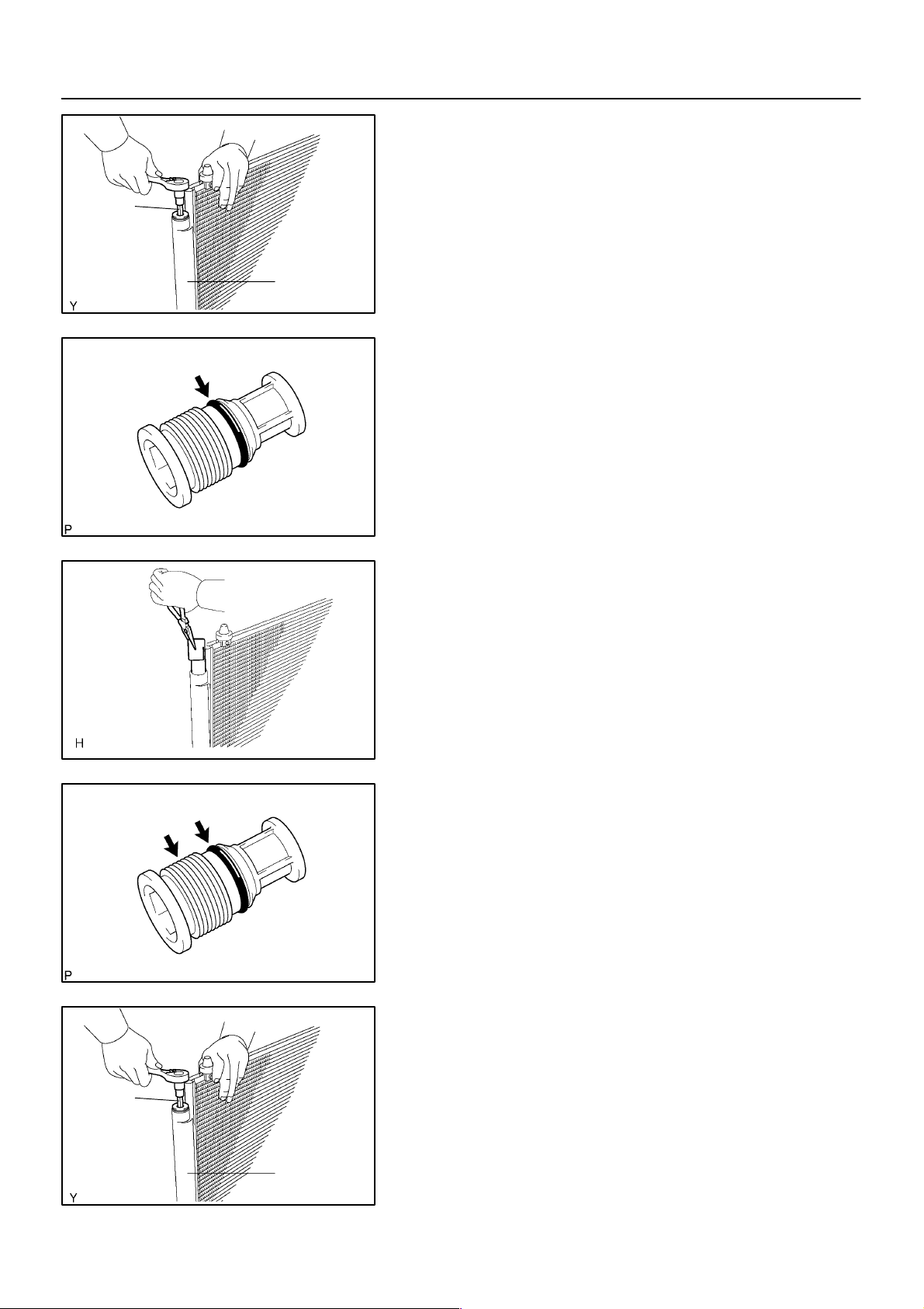
5. REMOVE COOLER DRYER
(a) Using a socket hexagon wrench 14 mm (0.55 in.), remove
the cap from the modulator.
Modulator
I30086
(b) Remove the O–ring from the cap.
E55408
I32475
(c) Using pliers, remove the cooler dryer.
6. INSTALL COOLER DRYER
(a) Using pliers, install the cooler dryer.
E50386
(b) Install the new O–ring to the cap.
(c) Sufficiently apply compressor oil to the fit surfaces of the
O–ring and the cap.
Compressor oil: ND–OIL 8 or equivalent
E55408
14 mm
(0.55 in.)
Hexagon
Wrench
2004 COROLLA (RM1037U)
(d) Using a socket hexagon wrench 14 mm (0.55 in.), install
the cap to the modulator.
Torque: 2.9 N⋅m (29 kgf⋅cm, 25 in.⋅lbf)
Modulator
I30086
1612Author!: Date!:
Page 9
I32453
I32451
55–43
–HEATER & AIR CONDITIONER W/RECEIVER CONDENSER ASSY
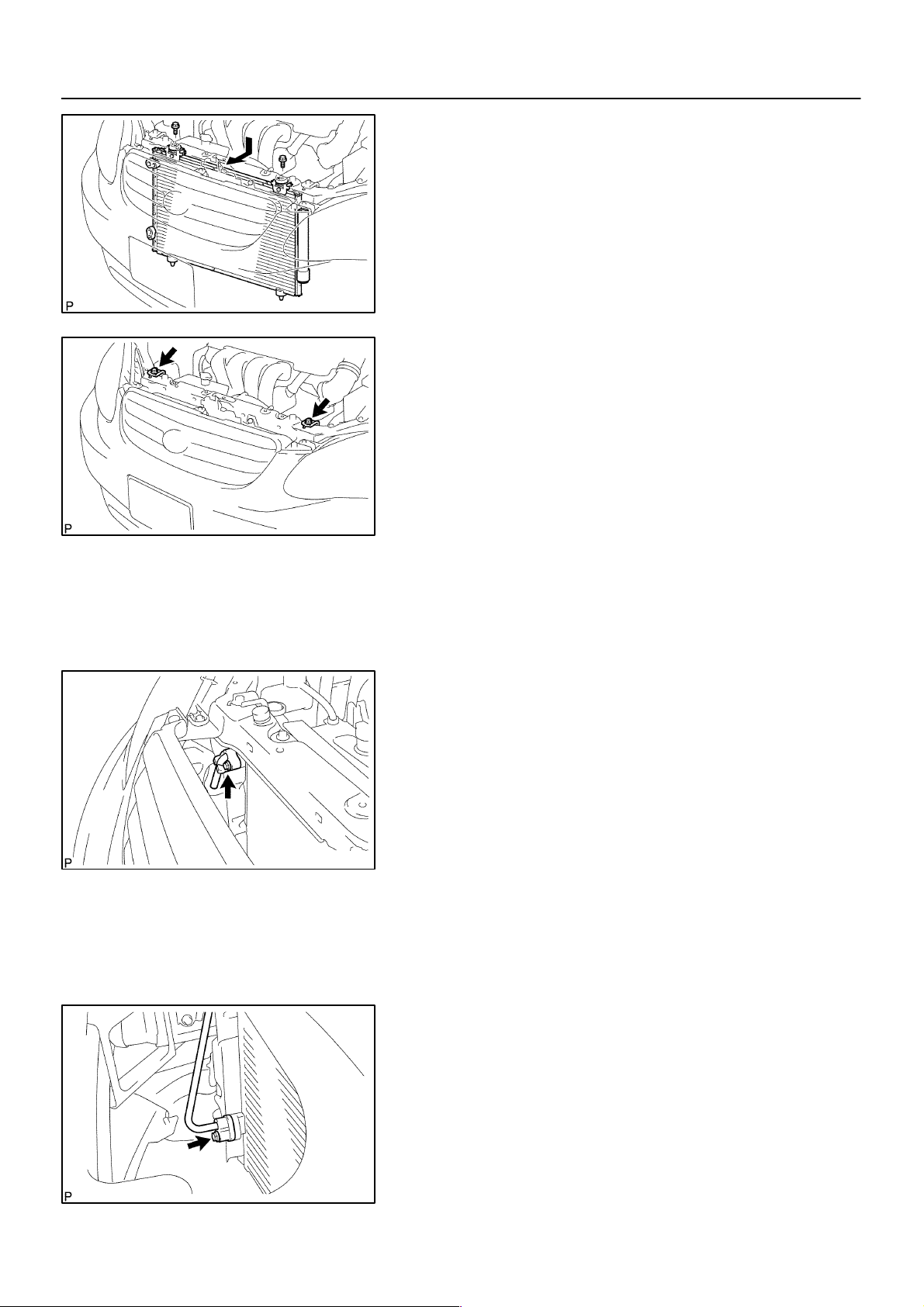
7. INSTALL W/RECEIVER CONDENSER ASSY
(a) Install the w/receiver condenser assy with the 2 bolts.
Torque: 9.8 N⋅m (100 kgf⋅cm, 87 in.⋅lbf)
(b) Install the 2 radiator upper supports with the 2 bolts.
8. INSTALL DISCHARGE HOSE SUB–ASSY
(a) Remove the attached vinyl tape from the hose and con-
necting part of the w/receiver condenser assy.
(b) Sufficiently apple compressor oil to the new O–ring and
hose joint.
Compressor oil: ND–OIL 8 or equivalent
(c) Install a O–ring to the discharge hose sub–assy.
I32450
(d) Install the discharge hose sub–assy to the w/receiver
condenser assy with the bolt.
Torque: 5.4 N⋅m (54 kgf⋅cm, 48 in.⋅lbf)
9. INSTALL COOLER REFRIGERANT LIQUID PIPE A
(a) Remove the attached vinyl tape from the pipe and w/re-
ceiver condenser assy.
(b) Sufficiently apple compressor oil to the new O–ring and
pipe joint.
Compressor oil: ND–OIL 8 or equivalent
(c) Install a O–rings to the cooler refrigerant liquid pipe A.
(d) Install the cooler refrigerant liquid pipe A to the w/receiver
condenser assy with the bolt.
Torque: 5.4 N⋅m (54 kgf⋅cm, 48 in.⋅lbf)
2004 COROLLA (RM1037U)
I31967
1613Author!: Date!:
Page 10

55–44
–HEATER & AIR CONDITIONER W/RECEIVER CONDENSER ASSY
10. CHARGE REFRIGERANT (See page 55–11)
SST 07110–58060 (07117–58060, 07117–58070, 07117–58080, 07117–58090, 07117–78050,
07117–88060, 07117–88070, 07117–88080), 07117–48130, 07117–48140
Specified amount: 490 ! 30 g (17.28 ! 1.06 oz.)
11. WARM UP ENGINE
12. INSPECT LEAKAGE OF REFRIGERANT (See page 55–11)
2004 COROLLA (RM1037U)
1614Author!: Date!:
Page 11

55–39
–HEATER & AIR CONDITIONER W/RECEIVER CONDENSER ASSY
W/RECEIVER CONDENSER ASSY
550IW–01
ON–VEHICLE INSPECTION
1. INSPECT W/RECEIVER CONDENSER ASSY
(a) If a fin of the w/receiver condenser assy is dirty, clean it with water and dry it with compressor air.
NOTICE:
Do not damage the fin of the w/receiver condenser assy.
(b) If a fin of the w/receiver condenser assy is bent, make it straight using a screwdriver or pliers.
2. INSPECT W/RECEIVER CONDENSER ASSY FOR LEAKAGE OF REFRIGERANT
(a) Using a halogen leak detector, check pipe joints for gas leakage.
(b) If gas leakage is detected in a joint, check the torque of the joint.
2004 COROLLA (RM1037U)
1609Author!: Date!:
Page 12
55–40
COMPONENTS
–HEATER & AIR CONDITIONER W/RECEIVER CONDENSER ASSY
550IX–01
9.8 (100, 87 in.⋅lbf)
! O–Ring
! O–Ring
W/receiver Condenser Assy
5.4 (54, 48 in.⋅lbf)
Cooler Dryer
! O–Ring
N⋅m (kgf⋅cm, ft⋅lbf) : Specified torque
Compressor Oil ND–OIL 8 or equivalent
! Non–reusable part
2004 COROLLA (RM1037U)
Cap
2.9 (29, 25 in.⋅lbf)
I32505
1610Author!: Date!:
Page 13

73–7
–THEFT DETERRENT & DOOR LOCK WIRELESS DOOR LOCK CONTROL SYSTEM
WIRELESS DOOR LOCK CONTROL SYSTEM
730B0–02
PRECAUTION
1. NOTICES WHEN CHECKING
(a) Power door LOCK/UNLOCK function:
The wireless remote control function operates only when the following 3 conditions are met.
(1) No key is inserted into the ignition key cylinder.
(2) All the doors are closed. However, doors can be unlocked even when any of the doors is opened.
(3) The power door lock system operates normally.
HINT:
! The UNLOCK function operates even when a door is open.
! The UNLOCK function operates even when the key is inserted into the ignition key cylinder, however
it must be in the OFF position.
(b) Remote panic function:
The wireless remote control function operates only when the following condition is met.
(1) The ignition switch is OFF.
HINT:
The key can be inserted, however it must be in the OFF position.
(c) The wireless door lock remote control operational area differs depending on the situation.
(1) The operational area differs depending on the operators and the ways the transmitter is held.
(2) In certain areas, the remote control function will only operate partially for the operational area
will be reduced due to the vehicle body shape and the influence of the surrounding environment.
(3) Since the transmitter uses faint electric waves, strong electric waves or noise in the frequency
used may reduce the operational area or the remote control may not function.
(4) When the battery weakens, the operational area is reduced or the remote control may not func-
tion.
HINT:
If the door control transmitter has been left in a place that is exposed to direct sunlight, such as on the instrument panel, it may cause the battery to weaken or cause other such problems.
2004 COROLLA (RM1037U)
1799Author!: Date!:
Page 14

73–8
–THEFT DETERRENT & DOOR LOCK WIRELESS DOOR LOCK CONTROL SYSTEM
730B1–02
ON–VEHICLE INSPECTION
1. INSPECT WIRELESS DOOR LOCK CONTROL FUNCTIONS
HINT:
! The switch described in this text is a switch for transmitting signals (LOCK switch, UNLOCK switch
and PANIC switch) which is built into the door control transmitter.
! All the functions listed below must be checked in the remote control operational area.
(a) Put the vehicle under the conditions that allow the wireless control function to be operated (See PRE-
CAUTION on page 73–7).
(b) Check the basic function.
(1) Check that all the doors lock when the LOCK switch is pressed.
(2) Check that only the driver side door unlocks when the UNLOCK switch is pressed once and the
other doors unlock when the UNLOCK switch is pressed again within 3 seconds.
(c) Check the chattering prevention function.
(1) Check that the corresponding operation occurs only once and is not repeated continuously while
the switch is held. However, when the switch is operated repeatedly at 1 second intervals, check
that the corresponding operation is carried out.
(d) Check the automatic lock function.
(1) Check that all the doors lock automatically as long as none of them have been opened or all the
doors have not been locked within approx. 30 seconds after they are unlocked by pressing the
UNLOCK switch.
(2) Check that the automatic locking function does not operate when any door has been opened or
all of them have been locked within approx. 30 seconds after they are unlocked by pressing the
UNLOCK switch.
(e) Check the switch operation fail–safe function.
(1) Check that the doors can not be locked using the switch while the key is in the ignition key cylin-
der. However, this does not apply when the system is in the recognition code registration mode.
(f) Check the operation stop function when a door is open or not completely closed.
(1) Check that the doors are not locked by the switch while any door is open or not completely closed.
However, the glass hatch open operation is possible in this situation.
(g) Check the repeat function.
(1) Check that all the doors attempt to automatically lock once again 1 second after the LOCK switch
has been pressed while the movement of the driver side door control knob is being restricted
while in the unlocked position.
(h) Check the hazard warning lamps flashing functions (answer–back).
(1) When the LOCK switch is pressed, check that the lamps flash once with the locking of all the
doors.
(2) When the UNLOCK switch is pressed once, check that the lamps flash twice with the unlocking
of the driver side door.
(3) When the UNLOCK switch is pressed again within 3 seconds, check that the lamps flash twice
with the unlocking of all the doors.
(i) Check the remote panic alarm function.
(1) Check that the horn sounds, and the headlamps, the taillamps and the hazard warning lamps
flash for 60 seconds by the theft alarm function when the PANIC switch is pressed. Also, check
that the horn stops sounding and the lamps stop flashing when either switch of the transmitter
is pressed once again.
(j) Check the illuminated entry function.
(1) When all the doors are locked, pressing the UNLOCK switch causes the room lamp (when the
lamp switch is in the DOOR position) to illuminate simultaneously with the unlock operation.
(2) Check that the room lamp goes off in approx. 15 seconds if doors have not been opened.
2004 COROLLA (RM1037U)
1800Author!: Date!:
Page 15
–THEFT DETERRENT & DOOR LOCK WIRELESS DOOR LOCK CONTROL SYSTEM
73–9
Door Control Receiver
(Wire Harness Side)
D3
B59092
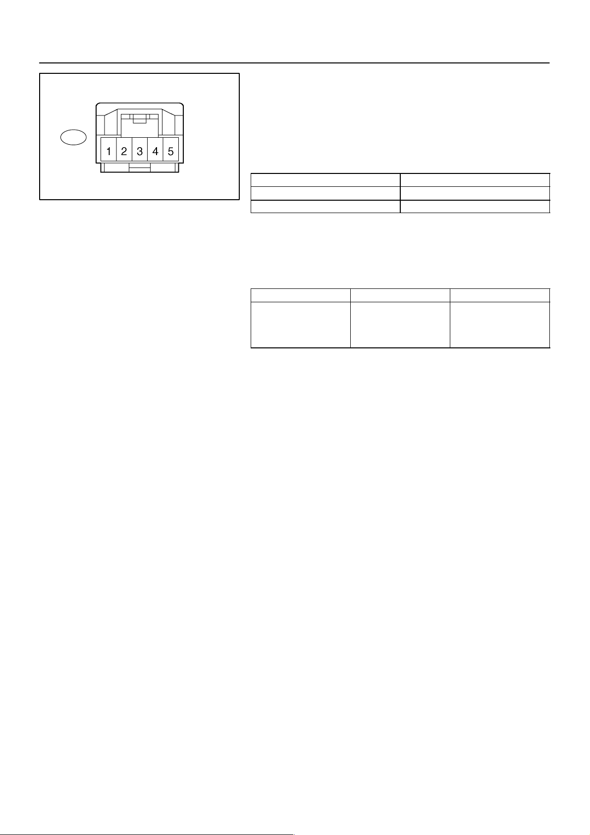
2. CHECK DOOR CONTROL RECEIVER
(a) Disconnect the D3 connector from the door control receiv-
er.
(b) Check the continuity and voltage between the terminals
of the door control receiver connector and the body
ground, as shown in the illustration and table.
Standard:
Symbols (Terminal No.) Specified condition
+B (D3– 5) – Body ground 10 – 14 V
GND (D3–1) – Body ground Continuity
If the result is not as specified, there may be a malfunction on
the wire harness side.
(c) Reconnect the connector and check the voltage between
the terminal and body ground.
Standard:
Symbols (Terminal No.) Condition Specified Condition
RDA (D3–2) –
Body ground
No key in ignition key
cylinder, all doors closed
and each transmitter
switch OFF → ON
1 V or less →
Approx. 6 – 7 V →
1 V or less
If the result is not as specified, the receiver may have a malfunction.
2004 COROLLA (RM1037U)
1801Author!: Date!:
Page 16
66–10
–WIPER & WASHER WIPER RUBBER LH
WIPER RUBBER LH
REPLACEMENT
1. REMOVE FR WIPER BLADE LH
(a) Remove the front wiper blade LH from the front wiper arm LH.
NOTICE:
Do not fold down the front wiper arm with the front wiper blade being removed from it.
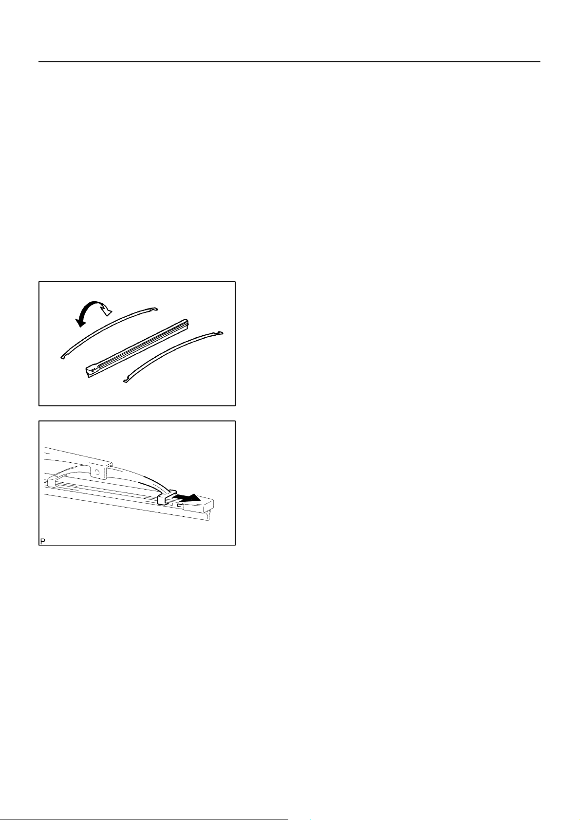
2. REMOVE WIPER RUBBER LH
(a) Remove the front wiper rubber LH from the front wiper blade.
(b) Remove the 2 wiper rubber backing plates from the wiper rubber LH.
3. INSTALL WIPER RUBBER LH
Curve
(a) Install the 2 wiper rubber backing plates to the wiper rub-
ber LH.
NOTICE:
Be careful to observe and keep direction of curvature for
correct replacement.
66072–01
E59361
E57398
(b) Install the wiper rubber LH so that the head part (Larger
side) of the wiper rubber faces the arm axie side.
NOTICE:
Push the front wiper blade into the grooves of the wiper
rubber to engage them completely.
2004 COROLLA (RM1037U)
1710Author!: Date!:
Page 17
66–6
–WIPER & WASHER WINDSHIELD WIPER MOTOR ASSY
WINDSHIELD WIPER MOTOR ASSY
REPLACEMENT
1. REMOVE WINDSHIELD WIPER ARM COVER
2. REMOVE FR WIPER ARM RH
(a) Operate the wiper and stop the windshield wiper motor assy at the automatic stop position.
(b) Remove a nut and FR wiper arm RH.
3. REMOVE FR WIPER ARM LH
(a) Remove a nut and FR wiper arm LH.
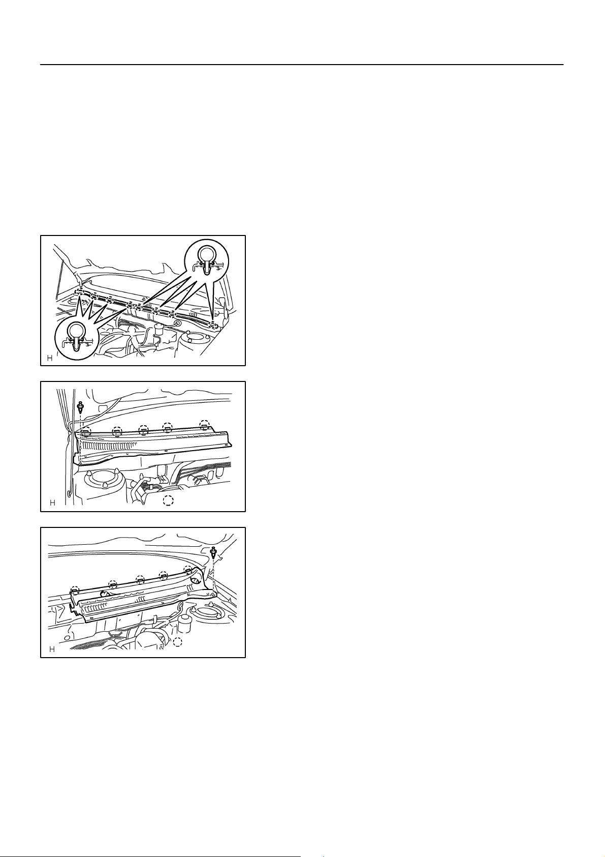
4. REMOVE HOOD TO COWL TOP SEAL
(a) Using a clipremover, disengage the meshing of 8 clips
and remove the hood to cowl top seal.
66071–01
Claws
Claws
E60623
5. REMOVE COWL TOP VENTILATOR LOUVER RH
(a) Remove a clip and release the 5 claws, and remove the
cowl top ventilator louver RH.
E60624
6. REMOVE COWL TOP VENTILATOR LOUVER LH
(a) Remove a clip and release the 5 claws, and remove the
cowl top ventilator louver LH.
E60625
2004 COROLLA (RM1037U)
1706Author!: Date!:
Page 18
E60708
66–7
–WIPER & WASHER WINDSHIELD WIPER MOTOR ASSY
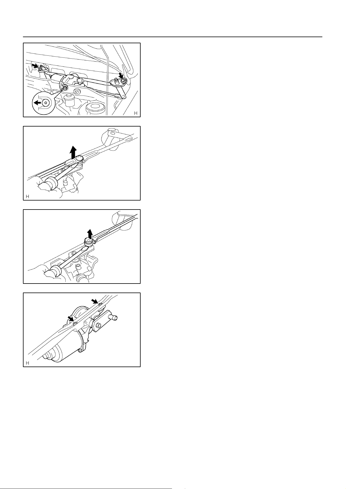
7. REMOVE WIPER LINK ASSY
(a) Disconnect the connector.
(b) Remove the 2 bolts.
(c) Slide the wiper link assy to vehicle’s passengers side. Dis-
engage the meshing of the rubber pin and remove the
wiper link assy.
8. REMOVE WINDSHIELD WIPER MOTOR ASSY
(a) Using a screwdriver and disengage the meshing of 2 rods
at the clank arm pivot of the windshield wiper motor assy.
HINT:
Tape the screwdriver tip before use.
E50396
E50397
E50398
(b) Remove 2 torx bolts and windshield wiper motor assy.
2004 COROLLA (RM1037U)
1707Author!: Date!:
Page 19
66–8
–WIPER & WASHER WINDSHIELD WIPER MOTOR ASSY
9. INSTALL WINDSHIELD WIPER MOTOR ASSY
(a) Apply MP grease to the clank arm pivot of the windshield wiper motor assy.
(b) Using 2 torx bolts, install the windshield wiper motor assy to the windshield wiper link assy.
Torque: 7.5 N⋅m (76 kgf⋅cm, 66 in.⋅lbf)
10. INSTALL WIPER LINK ASSY
(a) Install the meshing of the rubber pin.
(b) Install the windshield wiper link assy.with the 2 bolts.
Torque: 5.5 N⋅m (56 kgf⋅cm, 49 in.⋅lbf)
(c) Connect the connecter.
E60709
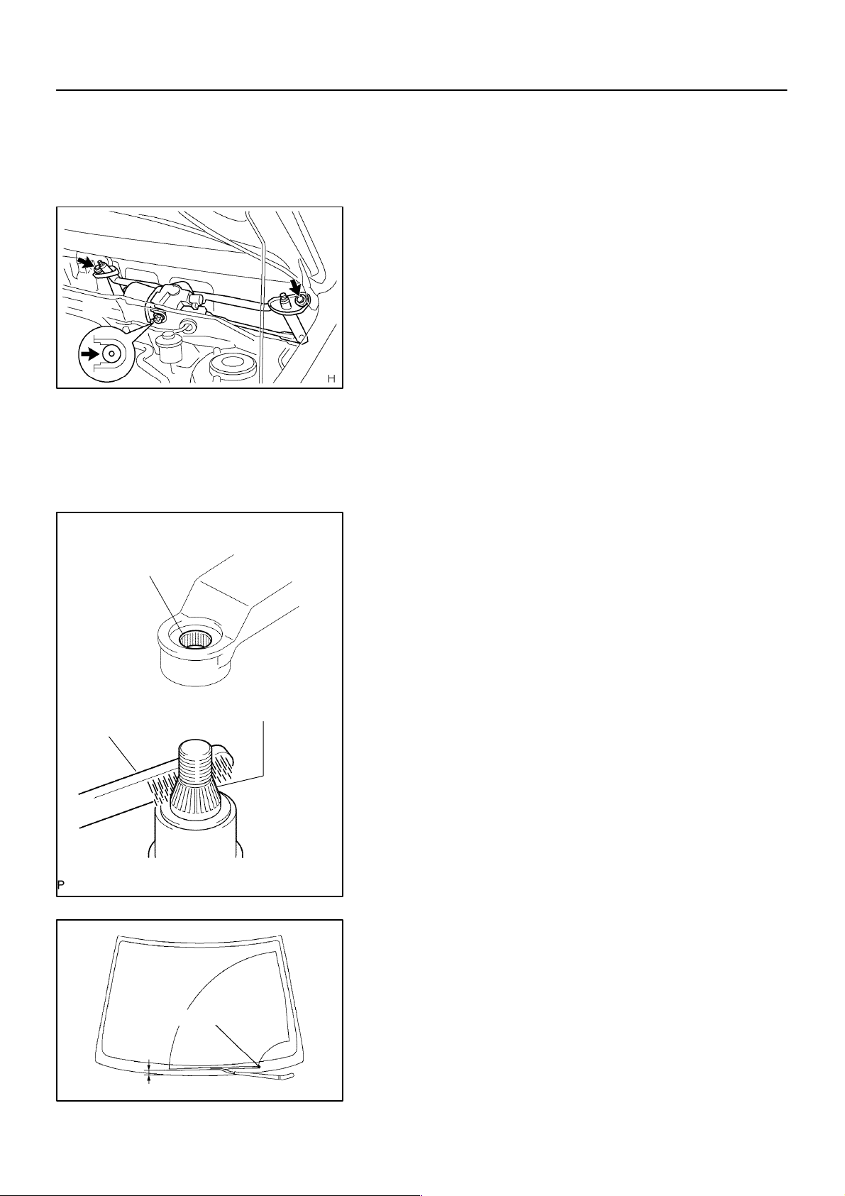
11. INSTALL FR WIPER ARM LH
(a) Operate the wiper, and stop the windshield wiper motor
assy at the automatic stop position.
Wiper Arm Serration
Wire Brush
Installation Position Mark
(b) Scrape off the serration part of the wiper arm with a round
file or equivalent.
(c) Clean the wiper pivot serration with the wire brush.
Wiper Pivot Serration
E58837
(d) Install the front wiper arm LH with a nut at the position as
shown in the illustration.
Torque: 20.5 N⋅m (209 kgf⋅cm, 15 ft⋅lbf)
HINT:
Hold down the arm hinge with hand to fasten a nut.
25 + 15.0mm (0.98 + 0.59in.)
2004 COROLLA (RM1037U)
E60710
1708Author!: Date!:
Page 20
Installation Position Mark
25 + 15.0mm (0.98 + 0.59in.)
66–9
–WIPER & WASHER WINDSHIELD WIPER MOTOR ASSY
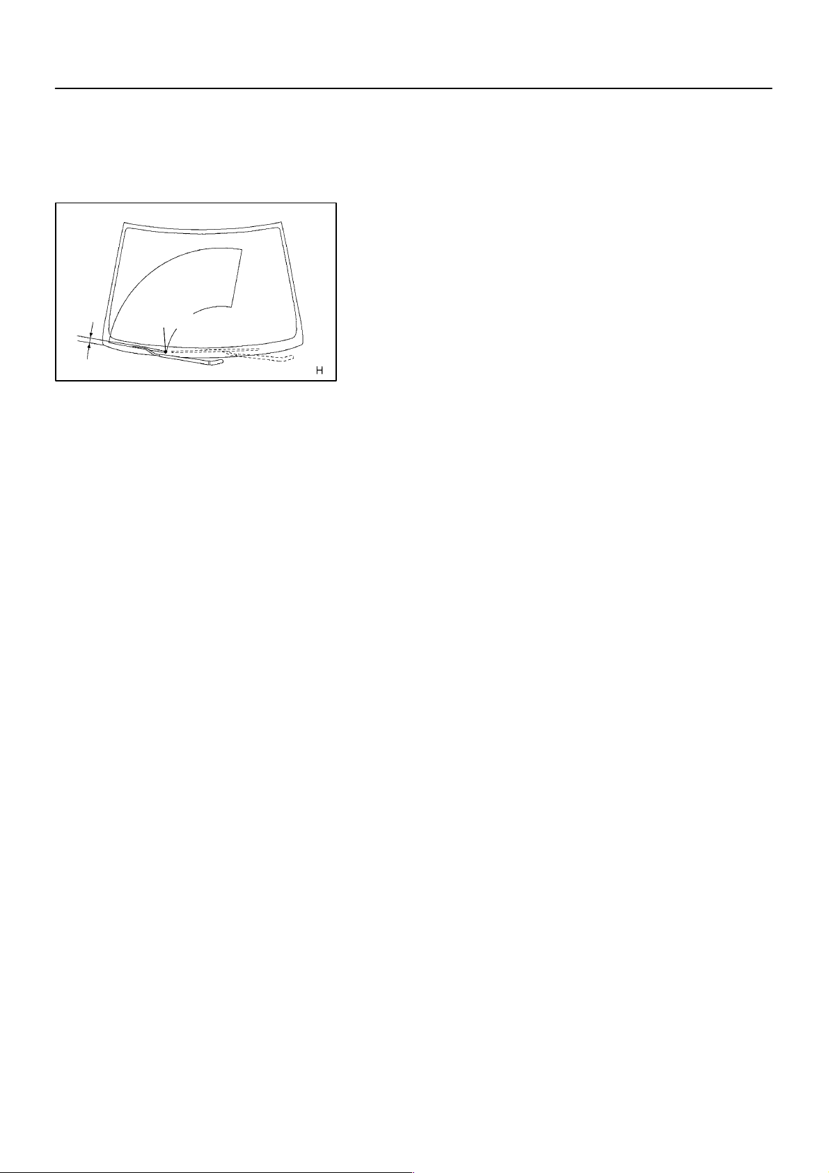
12. INSTALL FR WIPER ARM RH
(a) Scrape off the serration part of the wiper arm with a round
file or equivalent.
(b) Clean the wiper pivot serration with the wire brush.
(c) Install the front wiper arm RH with a nut to the position
shown in the illustration.
Torque: 20.5 N⋅m (209 kgf⋅cm, 15 ft⋅lbf)
HINT:
Hold down the arm hinge with hand to fasten a nut.
(d) Operate the wiper while running the water or the washer
fluid over the window, and check the wiping condition and
that the rear wiper does not hit against the vehicle body.
E60711
2004 COROLLA (RM1037U)
1709Author!: Date!:
Page 21

03–52
–SERVICE SPECIFICATIONS WIPER & WASHER
WIPER & WASHER
TORQUE SPECIFICATION
Part Tightened N⋅m kgf⋅cm ft⋅lbf
Wind shield wiper motor assy × Wiper link assy 7.5 76 66 in.⋅lbf
Wiper link assy × Body 5.5 56 49 in.⋅lbf
FR Wiper arm RH × Wiper link 20.5 209 15
FR Wiper arm LH × Wiper link 20.5 209 15
030PT–01
2004 COROLLA (RM1037U)
156Author!: Date!:
Page 22
WIPER & WASHER
PREPARATION
SST
02–47
–PREPARATION WIPER & WASHER
021C7–01
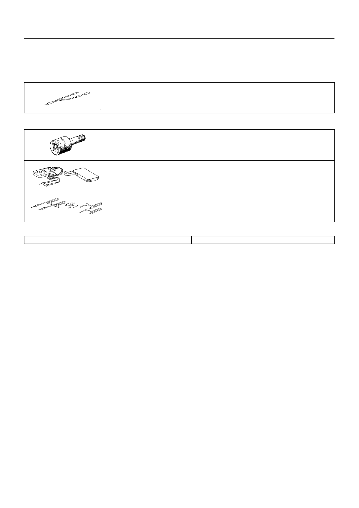
Recomended Tools
Equipment
To r qu e w r en c h
09843–18040
09042–00010
09082–00040
(09083–00150)
Diagnosis Check Wire No.2 WIPER AND WASHER SYSTEM
Torx Socket T30 WINDSHIELD WIPER MOTOR ASSY
TOYOTA Electrical Tester WIPER AND WASHER SYSTEM
Test Lead Set WIPER AND WASHER SYSTEM
2004 COROLLA (RM1037U)
92Author!: Date!:
Page 23
–WIPER & WASHER WINDSHIELD WIPER SWITCH ASSY
WINDSHIELD WIPER SWITCH ASSY
REPLACEMENT
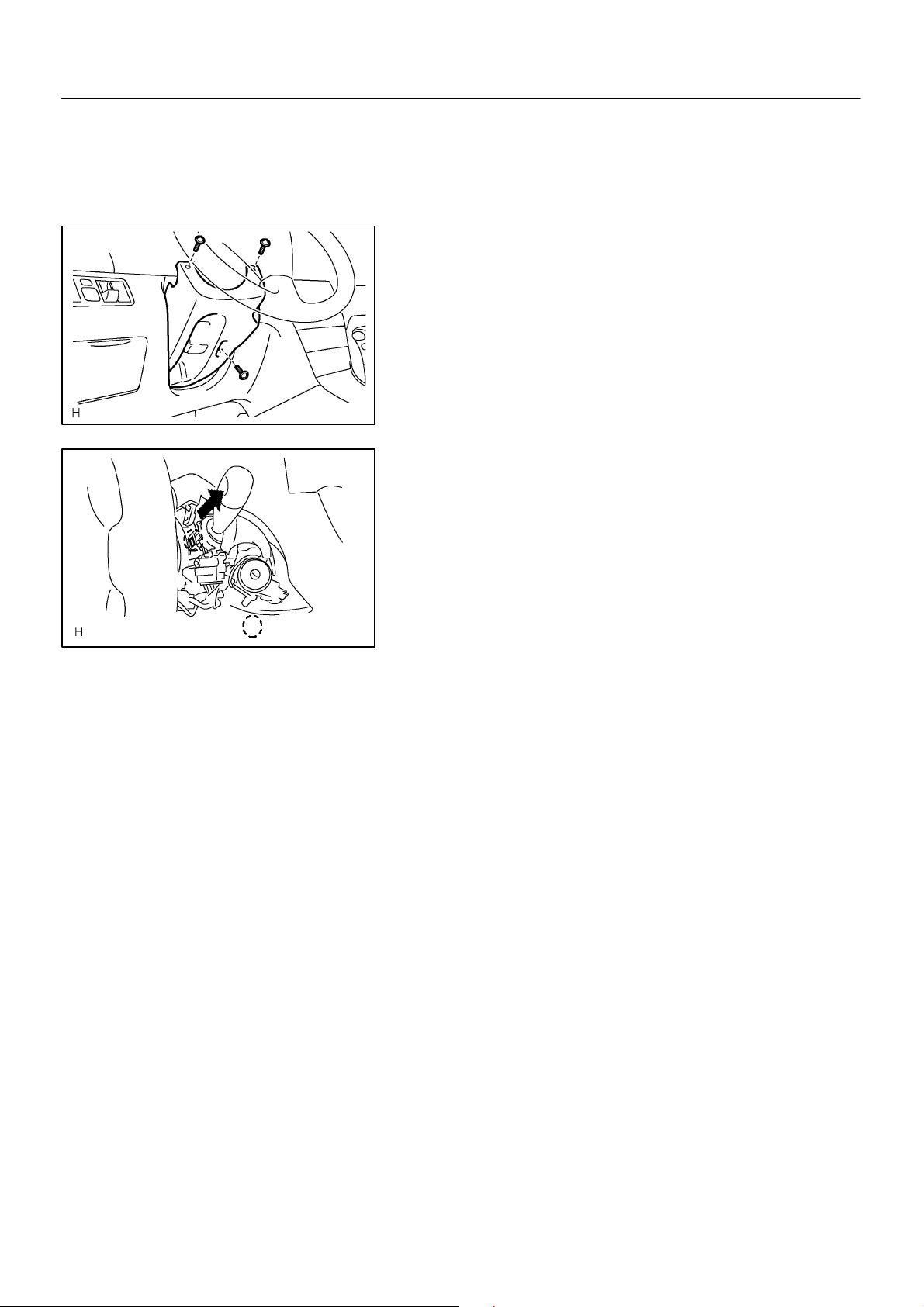
1. REMOVE STEERING COLUMN COVER LWR
(a) Remove 3 screws and steering column cover LWR.
E60462
2. REMOVE WINDSHIELD WIPER SWITCH ASSY
(a) Disconnect the connecter of the windshield wiper switch.
(b) Release the claw and pull out the windshield wiper switch
assy as shown in the illustration.
NOTICE:
Pressing the claw hard breaks the claw.
66–11
66073–01
Claw
E60688
2004 COROLLA (RM1037U)
1711Author!: Date!:
Page 24
–PREPARATION WINDSHIELD/WINDOWGLASS/MIRROR
WINDSHIELD/WINDOWGLASS/MIRROR
PREPARATION
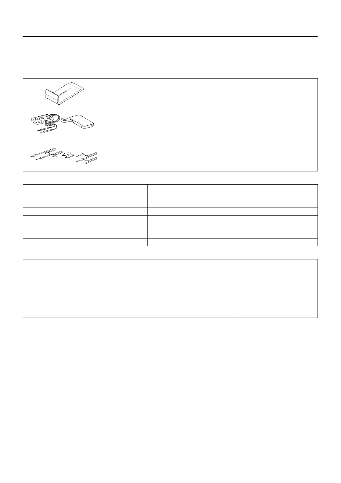
Recomended Tools
02–51
021CG–01
09070–20010
09082–00040
(09083–00150)
Moulding Remover WINDSHIELD GLASS
TOYOTA Electrical Tester WINDOW DEFOGGER SYSTEM
Test Lead Set POWER WINDOW CONTROL
Equipment
Adhesive
Knife
Piano wire Windshield
Plastic sheet To av o i d su r f a ce d a m ag e .
Sealer gun
To r qu e w r en c h
Tape To av o i d su r f a ce d a m ag e .
Wooden block or similar object For tying both piano wire ends
SSM
POWER MIRROR CONTROL
SYSTEM
POWER WINDOW CONTROL
SYSTEM
SYSTEM
08833–00030
08850–00801
Three cement black or equivalent WINDSHIELD GLASS
BACK WINDOW GLASS
Windshield Glass Adhesive Set
or equivalent
WINDSHIELD GLASS
BACK WINDOW GLASS
2004 COROLLA (RM1037U)
96Author!: Date!:
Page 25
70–10
–WINDSHIELD/WINDOWGLASS/MIRROR WINDSHIELD GLASS
REPLACEMENT
HINT:
Installation is according to the reverse order of the removal.
1. REMOVE FR WIPER ARM RH (See page 66–6)
2. REMOVE FR WIPER ARM LH (See page 66–6)
3. REMOVE HOOD TO COWL TOP SEAL (See page 66–6)
4. REMOVE COWL TOP VENTILATOR LOUVER LH (See page 66–6)
5. REMOVE COWL TOP VENTILATOR LOUVER RH (See page 66–6)
6. REMOVE FRONT DOOR WEATHERSTRIP RH (See page 76–21)
7. REMOVE FRONT DOOR WEATHERSTRIP LH (See page 76–21)
8. REMOVE FRONT PILLAR GARNISH RH (See page 76–21)
9. REMOVE FRONT PILLAR GARNISH LH (See page 76–21)
10. REMOVE INNER REAR VIEW MIRROR ASSY (See page 70–27)
11. REMOVE RH VISOR ASSY (See page 76–21)
12. REMOVE LH VISOR ASSY (See page 76–21)
13. REMOVE GLOVE BOX LAMP ASSY (See page 76–21)
14. REMOVE ASSIST GRIP SUB–ASSY (See page 76–21)
15. REMOVE VISOR HOLDER (See page 76–21)
16. REMOVE ROOF HEADLINING ASSY (See page 76–21)
17. REMOVE ROOF DRIP SIDE FINISH MOULDING CENTER RH (See page 76–17)
18. REMOVE ROOF DRIP SIDE FINISH MOULDING CENTER LH (See page 76–17)
700GO–01
2–Piece Type
1–Piece Type
Cut
Cut
19. REMOVE WINDSHIELD MOULDING OUTSIDE
(a) Using a knife, cut off the moulding as shown in the illustra-
tion.
NOTICE:
Do not damage the body with the knife.
(b) Remove the remaining moulding.
HINT:
When removing, make a cut partly, pull and remove it by hand.
B50448
20. REMOVE WINDSHIELD GLASS
HINT:
Depending on a vehicle type, either a 1–piece type or a 2–piece
type of stopper is installed.
(a) Push a piano wire through between the body and glass
from the interior.
HINT:
Apply protective tape to the outer surface to keep the surface
from being scratched.
2004 COROLLA (RM1037U)
B58592
1745Author!: Date!:
Page 26
–WINDSHIELD/WINDOWGLASS/MIRROR WINDSHIELD GLASS
70–11
Stopper
(b) Tie both wire ends to wooden blocks or similar objects.
NOTICE:
! When separating the glass, take care not to damage
the paint and interior/exterior ornaments.
Piano Wire
! To prevent the piano wire to be cut, do not cross it.
(c) Cut the adhesive by pulling the piano wire around it.
(d) Using a suction rubber, remove the glass.
NOTICE:
B50449
Leave as much adhesive on the body as possible when cutting off the glass.
21. CLEAN WINDSHIELD GLASS
(a) Using a scraper, remove the damaged stoppers, dam and
adhesive sticking to the glass.
(b) Clean the outer circumference of the glass with white gas-
oline.
NOTICE:
! Do not touch the glass after cleaning it.
! Be careful not to damage the body.
BO3986
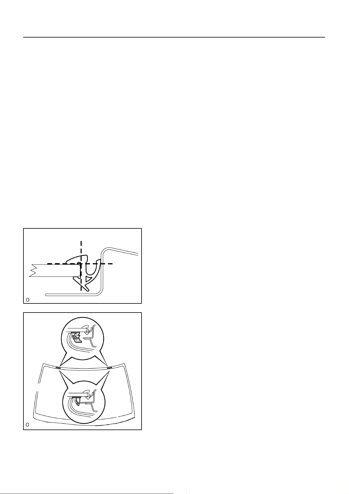
22. INSTALL WINDSHIELD GLASS STOPPER NO.1
(a) Install 2 new windshield glass stoppers No.1 to the body.
23. INSTALL WINDSHIELD GLASS STOPPER NO.2
(a) Coat the installation part of the stopper with Primer G.
NOTICE:
! Dry the primer coating for 3 minutes or more.
B
! Do not apply too much primer.
(b) Install 2 new windshield glass stoppers No.2 onto the
A
A
glass as shown in the illustration.
A: 40.0 mm (1.575 in.)
B59836
B: 7.7 mm (0.303 in.)
2004 COROLLA (RM1037U)
1746Author!: Date!:
Page 27
70–12
–WINDSHIELD/WINDOWGLASS/MIRROR WINDSHIELD GLASS
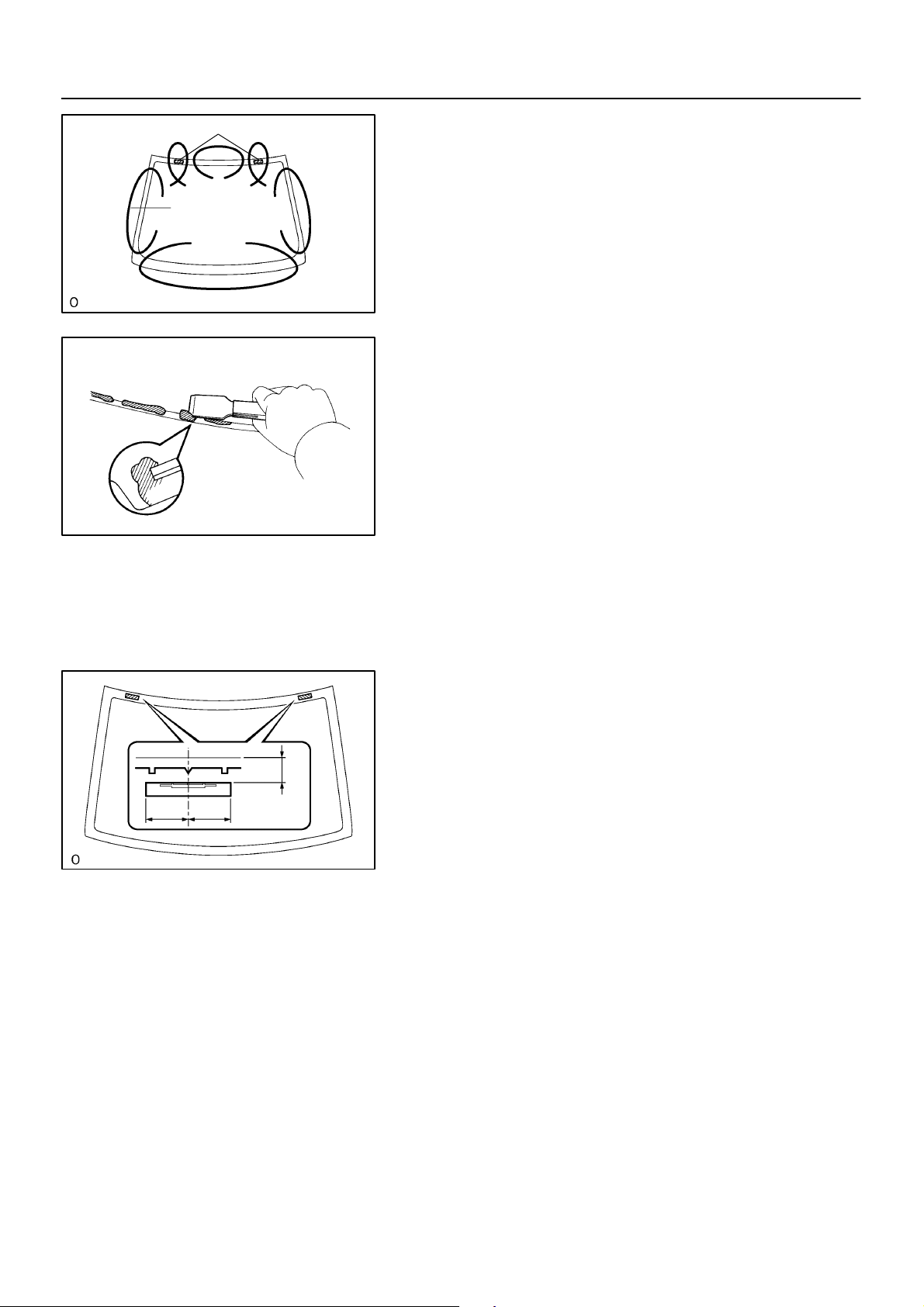
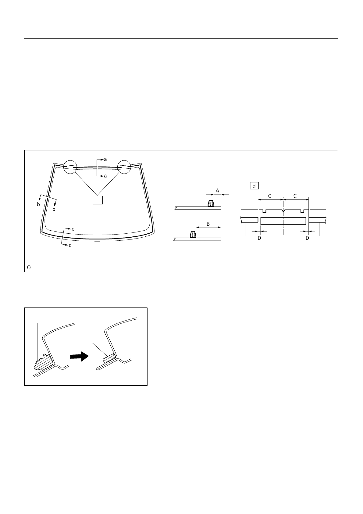
24. INSTALL FRONT PILLAR OUTER DAM
(a) Coat the installation part of the front pillar outer dam with Primer G.
NOTICE:
! Dry the primer coating for 3 minutes or more.
! Do not apply too much primer.
(b) Install 2 new front pillar outer dams with double–stick tape as shown in the illustration.
NOTICE:
Do not touch the glass face after cleaning it.
A: 7 mm (0.28 in.)
B: 22.5 mm (0.886 in.)
C: 45 mm (1.77 in.)
D: 5 mm (0.20 in.)
a – a
b – b
d
Adhesive
Adhesive
2004 COROLLA (RM1037U)
BO4420
c – c
Dam
Dam
B59167
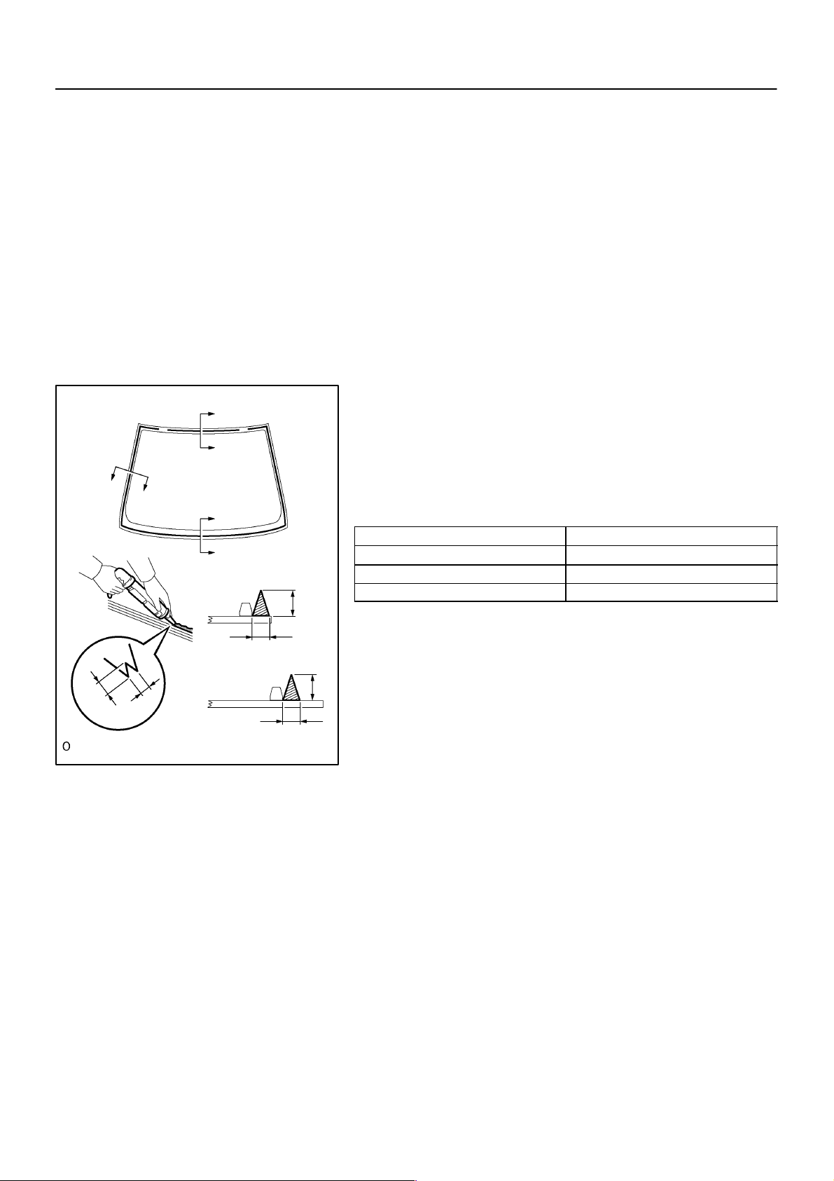
25. INSTALL WINDSHIELD GLASS
(a) Clean and shape the contact surface of the vehicle’s
body.
(1) Using a knife, cut away any rough areas on the
body.
HINT:
Leave as much adhesive on the body as possible.
(2) Clean the cut surface of the adhesive with a piece
of shop rag saturated in cleaner.
(b) Position the glass.
(1) Using a suction rubber, place the glass in the correct
position.
(2) Check that all the contacting parts of the glass rim
are perfectly even.
(3) Place reference marks between the glass and body.
NOTICE:
Check that the stoppers are attached to the body correctly.
HINT:
When reusing the glass, check and correct the reference mark’s
positions.
1747Author!: Date!:
Page 28
–WINDSHIELD/WINDOWGLASS/MIRROR WINDSHIELD GLASS
(4) Remove the glass.
(c) Coat the contact surface of the body panel with Primer M.
(d) Using a brush, coat the exposed part of the contact sur-
face on the vehicle side with Primer M.
NOTICE:
! Dry the primer coating for 3 minutes or more.
! Do not coat the adhesive with Primer M.
! Do not apply too much primer.
(e) Coat the contact surface of the glass with Primer G.
(1) Using a brush or sponge, coat the edge of the glass
and the contact surface with Primer G.
NOTICE:
! Dry the primer coating for 3 minutes or more.
! Do not apply too much primer.
(f) Apply adhesive.
a
(1) Cut off the tip of the cartridge nozzle as shown in the
illustration.
a
Part No. 08850–00801 or equivalent
HINT:
b
b
c
c
a – a
b – b
B
After cutting off the tip, use all adhesive within the time described in the table below.
Temperature Tackfree time
35"C (95"F) 15 minutes
20"C (68"F) 100 minutes
5"C (41"F) 8 hours
(2) Load the sealer gun with the cartridge.
c – c
A
(3) Coat the glass with adhesive, as shown in the il-
lustration.
A: 8.0 mm (0.315 in.) or more
B
A
B
B: 12.5 mm (0.492 in.) or more
(g) Install the glass.
A
B59952
(1) Using a suction rubber, position the glass so that the
reference marks are aligned, and press it in gently
along the rim.
NOTICE:
! Dry the primer coating for 3 minutes or more.
! Check that the stoppers are attached to the body cor-
rectly.
! Check the clearance between the body and glass.
(2) Lightly press the glass front surface for close con-
tact.
(3) Using a scraper, remove any excess or protruding
adhesive.
HINT:
Apply adhesive on the glass rim.
26. INSTALL WINDSHIELD MOULDING OUTSIDE
(a) Install a new windshield moulding to the windshield glass before the adhesive has hardened.
(b) Hold the
windshield glass in place securely with protective tape or equivalent until the adhesive has
completely hardened.
70–13
2004 COROLLA (RM1037U)
1748Author!: Date!:
Page 29

70–14
–WINDSHIELD/WINDOWGLASS/MIRROR WINDSHIELD GLASS
(c) Using a scraper, remove any excess or protruding adhesive before the adhesive has hardened.
NOTICE:
Take care not to drive the vehicle during the time described in the table below.
Temperature Tackfree time
35"C (95"F) 1.5 hours
20"C (68"F) 5 hours
5"C (41"F) 24 hours
27. INSPECT FOR LEAK AND REPAIR
(a) Conduct a leak test after the adhesive has completely hardened.
(b) Seal any leak with sealant.
2004 COROLLA (RM1037U)
1749Author!: Date!:
Page 30
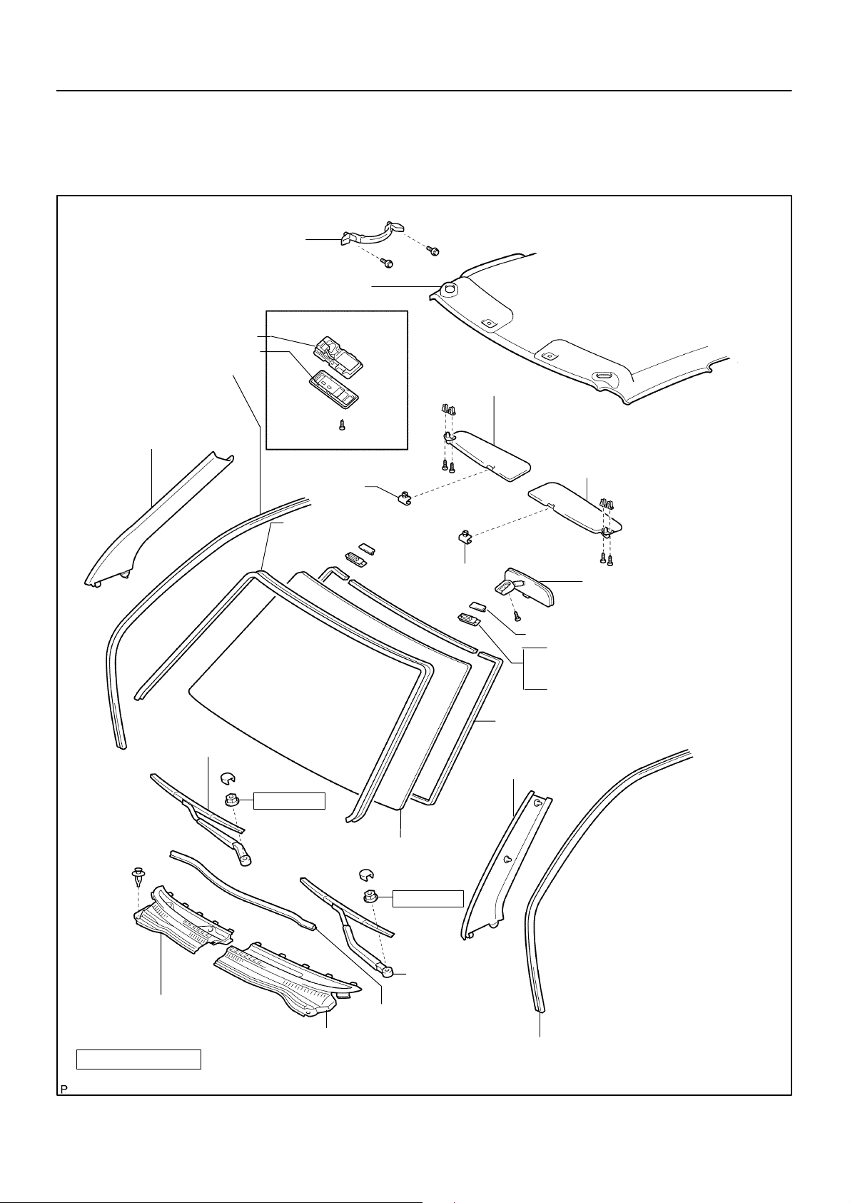
WINDSHIELD GLASS
COMPONENTS
Assist Grip Sub–assy
Roof Headlining Assy (Partial)
70–9
–WINDSHIELD/WINDOWGLASS/MIRROR WINDSHIELD GLASS
700GN–01
Glove Box Lamp Assy
Map Lamp Cover
Front Door Opening Trim
Weatherstrip RH
Front Pillar Garnish RH
w/ Sliding Roof
RH Visor Assy
Visor Holder
! Windshield Moulding Outside
Visor Holder
LH Visor Assy
Inner Rear View Mirror Assy
! Windshield Glass Stopper*
! Windshield Glass Stopper No.1*
! Windshield Glass Stopper No.2*
! Front Pillar Outer Dam
1
2
2
FR Wiper Arm RH
Cowl Top Ventilator Louver RH
N⋅m (kgf⋅cm ft⋅lbf)
: Specified torque
! Non–reusable part
2004 COROLLA (RM1037U)
20 (205, 15)
Windshield Glass
20 (205, 15)
FR Wiper Arm LH
Hood to Cowl Top Seal
Cowl Top Ventilator Louver LH
Front Pillar Garnish LH
*1:
1–piece type
*2:
2–piece type
Front Door Opening Trim Weatherstrip LH
B59170
1744Author!: Date!:
Page 31

70–22
PROBLEM SYMPTOMS TABLE
Symptom Suspected Area See page
Rear window defogger does not operate
(Indicator lamp on)
Rear window defogger does not operate
(Indicator lamp off)
–WINDSHIELD/WINDOWGLASS/MIRROR WINDOW DEFOGGER SYSTEM
1. M–HTR/DEF IUP fuse
2. DEF fuse
3. DEF relay
4. Rear window defogger wire
5. Wire harness
1. GAUGE fuse
2. Defogger switch (A/C panel switch)
3. Air control assembly
4. Wire harness
700GS–01
–
68–1
–
70–23
–
2004 COROLLA (RM1037U)
1757Author!: Date!:
Page 32

–WINDSHIELD/WINDOWGLASS/MIRROR WINDOW DEFOGGER SYSTEM
WINDOW DEFOGGER SYSTEM
LOCATION
Instrument Panel J/B
Defogger Relay
70–21
700GR–01
Defogger Wire
Instrument Panel J/B
GAUGE Fuse
2004 COROLLA (RM1037U)
M–HTR/DEF IUP Fuse
Defogger Fuse
B59159
1756Author!: Date!:
Page 33

INSPECTION
B16200
70–23
–WINDSHIELD/WINDOWGLASS/MIRROR WINDOW DEFOGGER SYSTEM
700GT–01
1. INSPECT DEFOGGER RELAY (Marking: DEF)
(a) Remove the defogger relay from the instrument panel
J/B.
(b) Inspect the defogger relay.
Standard:
Terminal No. Condition Specified condition
1 ⇔ 2 Constant Continuity
3 ⇔ 5
Apply B+ between
terminals 1 and 2
Continuity
If the result is not as specified, replace the relay.
2004 COROLLA (RM1037U)
1758Author!: Date!:
Page 34

16–8
WATER PUMP ASSY
REPLACEMENT
1. REMOVE ENGINE UNDER COVER RH
2. DRAIN COOLANT (See page 16–7)
3. REMOVE FAN AND GENERATOR V BELT
–COOLING WATER PUMP ASSY
160C9–01
(See page 14–4)
B00145
B00143
B00147
4. REMOVE GENERATOR ASSY
(a) Disconnect the wire clamp from the wire clip on the recti-
fire end frame.
(b) Remove the rubber cap and nut, and disconnect the alter-
nator wire.
(c) Disconnect the alternator connector.
(d) Remove the 2 bolts and alternator.
2004 COROLLA (RM1037U)
5. REMOVE WATER PUMP ASSY
(a) Remove the 6 bolts, water pump and O–ring.
B00150
1190Author!: Date!:
Page 35

16–9
–COOLING WATER PUMP ASSY
6. INSTALL WATER PUMP ASSY
B
(a) Place a new O–ring on the timing chain cover.
(b) Install the water pump with the 6 bolts.
B
A
B
Torque:
Bolt A 9.0 N⋅m (92 kgf⋅cm, 80 in⋅lbf)
Bolt B 11 N⋅m (113 kgf⋅cm, 8 ft⋅lbf)
B
A
A32555
7. INSTALL GENERATOR ASSY
Torque:
12 mm head 25 N⋅m (250 kgf⋅cm, 18 ft⋅lbf)
14 mm head
54 N⋅m (550 kgf⋅cm, 39 ft⋅lbf)
8. ADD COOLANT (See page 16–7)
9. CHECK ENGINE COOLANT LEAK (See page 16–7)
2004 COROLLA (RM1037U)
1191Author!: Date!:
Page 36

16–10
INSPECTION
–COOLING WATER PUMP ASSY
160CA–01
1. INSPECT WATER PUMP ASSY
(a) Visually check the drain hole for coolant leakage.
Hole
B10233
2004 COROLLA (RM1037U)
1192Author!: Date!:
Page 37

66–12
–WIPER & WASHER WASHER NOZZLE
WASHER NOZZLE
66074–01
ADJUSTMENT
1. INSPECT WASHER NOZZLE
(a) With the engine running, check that the point where the washer fluid hits the windshield and the rear
window is within the range indicated by the hatched line.
Ceramic Line
A
A
I
A:150mm(5.91in.)
B:440mm(17.32in.)
C:180mm(7.09in.)
D:260mm(10.24in.)
A
A
B
C
H
D
F
A
A
B
C
G
D
E
J
E:455mm(17.91in.)
F:465mm(18.31in.)
G:65mm(2.56in.)
H:70mm(2.76in.)
I:200mm(7.87in.)
J:155mm(6.10in.)
2004 COROLLA (RM1037U)
E60687
1712Author!: Date!:
Page 38

–DIAGNOSTICS COMBINATION METER
WARNING BUZZER DOES NOT SOUND (KEY REMINDER
WARNING, LIGHT REMINDER WARNING)
WIRING DIAGRAM
Combination Meter
RH J/B
U1
Unlock Warning SW
W–B
1
L–B(*1)
2
Instrument Panel J/B
15
4A
14
4A
L–B(*1)
L–B(*2)
16
C9
05–659
057T3–02
KEY SW
IE
Integration Relay
DCTY
A
J6
J/C
*1: w/ Door Lock Control
*2: w/o Door Lock Control
5
IL
ID
3
R–W
1
R–W
D4
Door Courtesy SW
(Driver’s Side)
1
17
C9
D–DOOR
I32381
INSPECTION PROCEDERE
1 CHECK BUZZER
(a) Check that all of the warning buzzers sound.
A B
Some buzzers sound No buzzer sounds
B CHECK AND REPLACE COMBINATION METER
A
2004 COROLLA (RM1037U)
ASSY
824Author!: Date!:
Page 39

05–660
–DIAGNOSTICS COMBINATION METER
2 INSPECT FRONT DOOR COURTESY LAMP SWITCH ASSY(See Page 65–7)
NG REPLACE FRONT DOOR COURTESY LAMP
SWITCH ASSY
OK
3INSPECT UN–LOCK WARNING SWITCH ASSY(See Page 05–682)
NG REPLACE UN–LOCK WARNING SWITCH ASSY
OK
4CHECK HARNESS AND CONNECTOR(BETWEEN UN–LOCK WARNING SWITCH
AND COMBINATION METER ASSY)
NG REPAIR OR REPLACE HARNESS OR
CONNECTOR
OK
5CHECK HARNESS AND CONNECTOR(BETWEEN COURTESY LAMP SWITCH AND
COMBINATION METER ASSY)
NG REPAIR OR REPLACE HARNESS OR
CONNECTOR
OK
CHECK AND REPLACE COMBINATION METER ASSY
2004 COROLLA (RM1037U)
825Author!: Date!:
Page 40

05–617
–DIAGNOSTICS AUDIO SYSTEM (April, 2003)
057P4–02
SOUND QUALITY IS BAD IN ALL MODES (VOLUME IS TOO LOW)
WIRING DIAGRAM
See page 05–614
INSPECTION PROCEDURE
1ADJUST SOUND QUALITY
(a) Adjust the sound quality.
(1) Operate the radio receiver assy to adjust the sound quality.
Standard: malfunction disappear.
OK BAD SOUND QUALITY
NG
2 COMPARE IT WITH ANOTHER CAR OF SAME MODEL
(a) Compare it with another vehicle of the same model.
(1) Compare with the vehicle of the same type which does not have a trouble to see if there is any
difference in the condition of trouble occurrence.
Standard: No difference found.
OK SETTING
NG
3CHECK HARNESS AND CONNECTOR(BETWEEN RADIO RECEIVER ASSY AND
SPEAKER)
NG REPAIR OR REPLACE HARNESS OR
CONNECTOR
OK
4INSPECT FRONT NO.1 SPEAKER ASSY
(a) Preparation for Check
(1) Disconnect the connector of the speaker.
(b) Resistance Check
(1) Check the resistance between the terminals of the speaker.
NOTICE:
The speaker should not be removed for checking.
Standard value: 4 Ω
OK
2004 COROLLA (RM1037U)
NG REPLACE FRONT NO.1 SPEAKER ASSY
782Author!: Date!:
Page 41

05–618
–DIAGNOSTICS AUDIO SYSTEM (April, 2003)
5INSPECT FRONT NO.2 SPEAKER ASSY
(a) Check that malfunction disappear when a known good speaker is installed.
Standard: malfunction disappear.
HINT:
Connect the all connectors of speakers.
NG REPLACE FRONT NO.2 SPEAKER ASSY
OK
6INSPECT REAR SPEAKER ASSY
(a) Preparation for Check
(1) Disconnect the connector of the speaker.
(b) Resistance Check
(1) Check the resistance between the terminals of the speaker.
NOTICE:
The speaker should not be removed for checking.
Standard value: 6 Ω
NG REPLACE REAR SPEAKER ASSY
OK
7INSPECT RADIO RECEIVER ASSY(+B, ACC, GND)
+B
ACC
GND
I32244
(a) Check that the continuity between terminals at each
condition, as shown in the chart.
Standard:
Te s te r c o nn e c t i on Condition Specified condition
GND – Body ground Constant Continuity
(b) Check that the voltage between terminals at each condi-
tion, as shown in the chart.
Standard:
Te s te r c o nn e c t i on Condition Specified condition
+B – GND Constant 10 – 14 V
ACC – GND Ignition switch ACC or ON 10 – 14 V
OK CHECK AND REPLACE RADIO RECEIVER
ASSY
NG
REPAIR OR REPLACE HARNESS OR CONNECTOR
2004 COROLLA (RM1037U)
783Author!: Date!:
Page 42

73–14
–THEFT DETERRENT & DOOR LOCK TOYOTA VEHICLE INTRUSION PROTECTION
SYSTEM
TOYOTA VEHICLE INTRUSION PROTECTION SYSTEM
730AV–01
ON–VEHICLE INSPECTION
1. OUTLINE OF TOYOTA VEHICLE INTRUSION PROTECTION (TVIP) SYSTEM
HINT:
The theft deterrent system has 2 modes; one is the active mode that is an initially set mode and another is
the passive mode that can be switched ON/OFF by the specified method (See step 4).
(a) When the theft deterrent system detects any theft, the system will sound the horns and flash the lights
to alert the people around the vehicle to the theft.
HINT:
Each mode (active and passive) has 4 states; disarmed state, arming preparation state, armed state, alarm
sounding state.
(1) Disarmed state:
! The user is near the vehicle.
! The alarming function does not operate.
! The theft deterrent function does not operate.
(2) Arming preparation state:
! Time from the user locks a door to leave the vehicle.
! Time for transferring to the armed state.
! The theft deterrent function does not operate.
(3) Armed state:
! The user leaves the vehicle completely.
! The theft deterrent function operates.
(4) Alarm sounding state:
Once a theft is detected in the armed state, the system will sound the horns and flash the lights
to alert the people around the vehicle to the theft.
Refer to the table for the alarming method and time.
Alarming method
Alarming time
Room Light
Headlight
Hazard Warning Light
Vehicle Horn
Illuminating (turn on)
Flashing at a cycle of approx. 0.4 sec.
Flashing at a cycle of flasher relay
Sounding at a cycle of approx. 0.4 sec.
Approx. 60 sec.
HINT:
In the alarm sounding state, when either of the front doors is unlocked and no key is inserted in the ignition
key cylinder, forced door lock signal is output.
2004 COROLLA (RM1037U)
1806Author!: Date!:
Page 43

2. ACTIVE ARMING MODE
–THEFT DETERRENT & DOOR LOCK TOYOTA VEHICLE INTRUSION PROTECTION
SYSTEM
73–15
Disarmed State
(No key inserted in ignition key cylinder)
Perform any of the followings and the system will go to ”Arming preparation state”:
" With all doors and luggage compartment door closed, lock all doors with key.
" With all doors and luggage compartment door closed, lock all doors by the wireless door
lock operation.
" With all doors and luggage compartment door closed, open and close either of doors or
luggage compartment door, and then close and lock all doors and luggage compartment
door.
Perform any of the followings and the system
will return to ”Disarmed state”:
" Open either of the closed doors or luggage
compartment door.
" Unlock either of the locked front doors.
" Insert the key in the ignition key cylinder.
" Disconnect the battery once, and then
reconnect it.
Continued from next page
Arming Preparation State
Perform the following and the system will
go to ”Armed state”:
" Allow 30 seconds to elapse with all doors
and luggage compartment door closed and
locked.
Continued to next page
2004 COROLLA (RM1037U)
1807Author!: Date!:
Page 44

73–16
–THEFT DETERRENT & DOOR LOCK TOYOTA VEHICLE INTRUSION PROTECTION
SYSTEM
Continued to previous page
Perform any of the followings and the system
will return to ”Disarmed state”:
" Unlock the locked doors by the wireless door
lock operation.
" Unlock the locked doors with key (except the
luggage compartment door).
" Insert the key into the ignition key cylinder
and turn the ignition ON.
Continued from previous page
Armed State
Perform any of the followings and the system
will go to ”Alarm sounding state”:
" Open either of the closed doors.
" Unlock either of the locked front doors in any
way other than the key and the wireless door
lock operations.
" Open the closed luggage compartment
door.
" Reconnect the battery terminal.
" Turn the ignition switch ON without using the
key.
" Theft is detected by the glass breakage
sensor.
Alarm Sounding State
Perform any of the followings and the system will return to ”Disarmed state”:
" Unlock the locked doors by the wireless
door lock operation.
" Unlock the locked doors with key (except
the luggage compartment door).
" Insert the key into the ignition key cylinder
and turn the ignition ON.
Once a theft is detected, lights will flash and
horns will sound to alert people around the
vehicle to the theft.
After the above specified alarming time (60
sec.) has elapsed, the system will return to
”Armed state”.
2004 COROLLA (RM1037U)
1808Author!: Date!:
Page 45

–THEFT DETERRENT & DOOR LOCK TOYOTA VEHICLE INTRUSION PROTECTION
SYSTEM
Indicator light output:
Condition Indicator light
Disarmed state OFF
Arming preparation state ON
Armed state BLINK
Alarm sounding state ON
HINT:
Blinking frequency:
0.2 seconds (ON)
1.8 seconds (OFF)
73–17
2004 COROLLA (RM1037U)
1809Author!: Date!:
Page 46

73–18
–THEFT DETERRENT & DOOR LOCK TOYOTA VEHICLE INTRUSION PROTECTION
SYSTEM
3. PASSIVE ARMING MODE
! This mode can be switched according to the specified method (See step 4).
! Initially set mode (when shipped from factory) is the active mode (No passive mode).
Disarmed State (A)
Perform the following and the system will go to ”Disarmed state (B)”:
" Insert and remove the key from the ignition key cylinder, and then open and close the driver’s door.
Disarmed State (B)
Perform any of the followings and the system
will return to ”Disarmed state (A)”:
" Push the unlock switch on the transmitter.
" Put the key in the lock cylinder on the driver’s
or passenger’s door and turn it towards unlock.
" Insert the key in the ignition key cylinder.
" Reconnect the battery terminal.
Arming Preparation State
Perform the following and the system will return to ”Disarmed state (B)”:
" Open either of the closed doors or luggage
compartment door.
Perform the following and the system will go to
”Arming preparation state”:
" Close all doors and luggage compartment
door.
Perform the following and the system will go to
”Armed state”:
" Allow 30 seconds to elapse with all doors and
luggage compartment door closed.
2004 COROLLA (RM1037U)
Continued from next page
Continued to next page
1810Author!: Date!:
Page 47

–THEFT DETERRENT & DOOR LOCK TOYOTA VEHICLE INTRUSION PROTECTION
SYSTEM
Continued from previous pageContinued to previous page
Armed State
73–19
Perform any of the followings and the system
will return to ”Disarmed state (A)”:
" Push the unlock switch on the transmitter.
" Put the key in the lock cylinder on the driver’s
or passenger’s door and turn it towards
unlock.
" Insert the key into the ignition key cylinder
and turn the ignition ON.
Alarm Sounding State
Perform any of the followings and the system will
go to ”Alarm sounding state”:
" Open either of the closed doors and allow the
entry delay time*1 to pass.
" Open the closed luggage compartment door.
" Reconnect the battery terminal.
" Turn the ignition ON without using the key.
*1: See the ”Entry delay function”
on the next page
Perform any of the followings and the system
will return to ”Disarmed state (A)”:
" Push the unlock switch on the transmitter.
" Put the key in the lock cylinder on the driver’s
or passenger’s door and turn it towards
unlock.
" Insert the key into the ignition key cylinder
and turn the ignition ON.
Perform the following and the system will return
to ”Armed state”:
" The alarm sounding time (60 sec.) has
elapsed.
2004 COROLLA (RM1037U)
1811Author!: Date!:
Page 48

73–20
–THEFT DETERRENT & DOOR LOCK TOYOTA VEHICLE INTRUSION PROTECTION
SYSTEM
Entry delay function:
HINT:
In the armed state, if either closed door is opened, entry delay time will start.
If the transferring condition (Armed state → Disarmed state) is satisfied during this entry delay time, the system will transfer to the disarmed state. However if the condition is not satisfied, the system will judge it to
be a theft, and then the system will transfer to the alarm sounding state.
Door
Close
Open
Indicator
ON
OFF
Alarming output
ON
OFF
Entry delay time
System condition
(0, 14, 30 sec.)
Armed state Alarm sounding
state
HINT:
The entry delay time can be selected among 0, 14, 30 seconds by the customizing function.
Indicator light output:
Condition Indicator light
Disarmed state OFF
Arming preparation state ON
Armed state (Entry delay time) BLINK (ON)
Alarm sounding state ON
HINT:
Blinking frequency:
0.2 seconds (ON)
1.8 seconds (OFF)
Transfer to the active mode:
HINT:
In each state of the passive mode, when the transferring condition to the active mode (disarmed state of
active mode → arming preparation state of active mode) is satisfied, the system will transfer to each state
of the active mode. In this case, the active mode will continue until the system transfers to the disarmed state.
State of Passive Mode Before Transfer State of Active Mode After Transfer
Disarmed state Arming preparation state
Arming preparation state Arming preparation state (continuing for 30 sec.)
Armed state
Armed state (During entry delay time)
Alarm sounding state
(After alarming time has elapsed, the system will transfer to the
armed state)
After alarming time has elapsed, the system will transfer to the
armed state
2004 COROLLA (RM1037U)
1812Author!: Date!:
Page 49

4. CHANGING METHOD OF PASSIVE MODE
(ON or OFF)
–THEFT DETERRENT & DOOR LOCK TOYOTA VEHICLE INTRUSION PROTECTION
SYSTEM
73–21
Within
5 sec.
Within
40 sec.
2 sec.
" No key in the ignition key cylinder
" Driver’s door opened
" All doors unlocked
Insert and remove the key from the ignition
key cylinder 3 times.
Close the driver’s door.
Lock and unlock all doors 3 times by the key
or remote control.
Open and close the driver’s door.
Lock and unlock the driver’s door lock knob
3 times.
Open the driver’s door.
( = Vehicle initial condition)
Input to the vehicle
Output from the vehicle
Within
20 sec.
2 sec.
The system starts forced door lock once
(answer back).
Unlock the driver’s door lock knob.
Close and open the driver’s door 3 to 5
Close and open the driver’s door 2 times
times
Lock and unlock the driver’s door lock
Lock and unlock the driver’s door lock knob.
knob.
* 0 sec.
The system starts forced door lock once
(answer back).
PASSIVE MODE OFF
The system starts forced door lock once
(answer back).
PASSIVE MODE ON
HINT:
" Initial mode is PASSIVE MODE OFF.
" If there is a different signal in the middle of changing, it is invalid.
*: Entry delay time
4 times 5 times3 times
* 14 sec. * 30 sec.
2004 COROLLA (RM1037U)
1813Author!: Date!:
Page 50

73–22
–THEFT DETERRENT & DOOR LOCK TOYOTA VEHICLE INTRUSION PROTECTION
SYSTEM
5. FORCED DOOR LOCK CONTROL
(a) Forced door lock is a control that prevents intrusion into vehicles. When a door is unlocked (when an
alarm starts), instantaneously forced door lock will be executed.
(1) Condition to execute forced door lock:
Detecting any or all of the following conditions activates forced door lock.
! Theft deterrent system is in the alarm sounding state of the active mode.
! No key is in the ignition key cylinder.
! Any of the front doors is unlocked.
! Since the previous forced door lock, 0.38 seconds or more have elapsed.
(2) Conditions to stop forced door lock:
Detecting any of the following conditions stops forced door lock.
! All doors are locked.
! The alarm has finished.
! The key is inserted into the key cylinder.
Glass Breakage Sensor ECU
Volume
B59188
6. OPERATE GLASS BREAKAGE SENSOR
(a) If the glass breakage sensor detects the glass is broken
(at 1st time), the sensor will issue an alarm for 20 seconds
(pre–alarming). If the glass breakage sensor detects the
glass is broken further more (at 2nd time), the sensor will
issue an alarm for 60 seconds.
(b) The sensitivity of the glass breakage sensor can be ad-
justed by the volume switch in the glass breakage sensor
ECU.
HINT:
Because the glass breakage sensor has a high sensitivity, it
might issue a wrong alarm if it is adjusted in the volume of high
sensitive.
2004 COROLLA (RM1037U)
1814Author!: Date!:
Page 51

01–4
–INTRODUCTION IDENTIFICATION INFORMATION
IDENTIFICATION INFORMATION
VEHICLE IDENTIFICATION AND SERIAL NUMBERS
1. VEHICLE IDENTIFICATION NUMBER
A
B
D27356
A
C
B
D27359
(a) The vehicle identification number is stamped on the ve-
hicle identification number plate and certification label, as
shown in the illustration.
A: Vehicle Identification Number Plate
B: Certification Label
2. ENGINE SERIAL NUMBER AND TRANSAXLE SERIAL
NUMBER
(a) The engine serial number is stamped on the cylinder
block of the engine, and the transaxle serial number is
stamped on the housing, as shown in the illustration.
A: 1ZZ–FE
B: C59
C: A245E
01031–06
2004 COROLLA (RM1037U)
7Author!: Date!:
Page 52

02–58
VEHICLE CONTROL SYSTEM
PREPARATION
Recomended Tools
–PREPARATION VEHICLE CONTROL SYSTEM
021CP–01
09082–00040
TOYOTA Electrical Tester IGNITION OR STARTER SWITCH
ASSY
2004 COROLLA (RM1037U)
103Author!: Date!:
Page 53

51–8
–POWER STEERING VANE PUMP ASSY
OVERHAUL
NOTICE:
! When using a vise, do not over tighten.
! When installing, coat the parts indicated by the arrows with power steering fluid
(See page 51–7).
1. REMOVE FRONT WHEEL RH
2. DRAIN POWER STEERING FLUID
3. REMOVE ENGINE UNDER COVER RH
4. REMOVE FAN AND GENERATOR V BELT
5. DISCONNECT OIL RESERVOIR TO PUMP HOSE NO.1
(a) Remove the clip and disconnect the oil reservoir to pump hose No.1.
6. DISCONNECT PRESSURE FEED TUBE ASSY
SST
(a) Using SST, disconnect the pressure feed tube assy.
SST 09023–38400
(b) Remove the bolt and disconnect the pressure feed tube
clamp.
5107W–01
F42474
7. REMOVE VANE PUMP ASSY
(a) Disconnect the oil pressure switch connector.
(b) Remove the 2 bolts, nuts and vane pump assy.
C80321
8. REMOVE VANE PUMP BRACKET REAR
(a) Remove the bolt and vane pump bracket rear.
9. FIX VANE PUMP ASSY
(a) Using SST, hold the vane pump assy in a vise.
SST 09630–00014 (09631–00132)
2004 COROLLA (RM1037U)
SST
F42477
1543Author!: Date!:
Page 54

51–9
–POWER STEERING VAN E PUM P ASS Y
10. REMOVE POWER STEERING SUCTION PORT UNION
(a) Remove the bolt and power steering suction port union.
(b) Remove the O–ring from the power steering suction port union.
11. REMOVE FLOW CONTROL VALVE
(a) Remove the pressure port union.
(b) Remove the O–ring from the pressure port union.
(c) Remove the flow control valve and flow control valve compression spring.
12. REMOVE POWER STEERING OIL PRESSURE SWITCH
NOTICE:
Be careful so that oil pressure switch is not dropped or strongly damaged, however if it is damaged
replace it with a new one.
13. REMOVE VANE PUMP HOUSING REAR
(a) Remove the 4 bolts and vane pump housing rear from the vane pump housing front.
(b) Remove the O–ring from the vane pump housing front.
14. REMOVE W/PULLEY SHAFT SUB–ASSY
(a) Using a screwdriver, remove the snap ring from the w/ pulley shaft sub–assy.
(b) Remove the w/ pulley shaft sub–assy.
15. REMOVE VANE PUMP ROTOR
(a) Remove the 10 vane plates.
(b) Remove the vane pump rotor.
16. REMOVE VANE PUMP CAM RING
C65368
C65369
17. REMOVE VANE PUMP SIDE PLATE FRONT
(a) Remove the side plate from the pump housing front.
(b) Remove the O–ring from the side plate front.
(c) Remove the O–ring from the pump housing front.
2004 COROLLA (RM1037U)
1544Author!: Date!:
Page 55

51–10
Vane Pump Shaft
SST
Bushing
Front Housing
–POWER STEERING VAN E PUM P ASS Y
18. REMOVE VANE PUMP HOUSING OIL SEAL
(a) Using SST and a hammer, remove the vane pump hous-
ing oil seal.
SST 09631–10030
NOTICE:
Be careful not to damage the pump housing.
F42143
19. INSPECT OIL CLEARANCE
(a) Using a micrometer and a caliper gauge, measure the oil
seal clearance.
Standard clearance:
0.021 – 0.043 mm (0.0008 – 0.0017 in.)
Maximum clearance: 0.07 mm (0.0028 in.)
If it is more than the maximum, replace the vane pump assy.
F09875
Height
Length
Thickness
Feeler Gauge
20. INSPECT VANE PUMP ROTOR AND VANE PLATES
(a) Using a micrometer, measure the height, thickness and
length of the vane plates.
Minimum height: 7.6 mm (0.299 in.)
Minimum thickness: 1.405 mm (0.0553 in.)
Minimum length: 11.993 mm (0.4722 in.)
N00372
(b) Using a feeler gauge, measure the clearance between a
side face of the vane pump rotor groove and vane plate.
Maximum clearance: 0.03 mm (0.0012 in.)
If it is more than the maximum, replace the vane pump assy.
R10282
21. INSPECT FLOW CONTROL VALVE
(a) Coat the flow control valve with power steering fluid and
check that it falls smoothly into the flow control valve hole
by its own weight.
2004 COROLLA (RM1037U)
F41493
1545Author!: Date!:
Page 56

Compressed Air
F41491 F41622
Vernier Calipers
51–11
–POWER STEERING VAN E PUM P ASS Y
(b) Check the flow control valve for leakage. Close one of the
holes and apply compressed air of 392 – 490 kPa (4 – 5
2
kgf⋅cm
, 57 – 71 psi) into the opposite side hole, and con-
firm that air does not come out from the end holes.
If necessary, replace the vane pump assy.
22. INSPECT FLOW CONTROL VALVE COMPRESSION
SPRING
(a) Using vernier calipers, measure the free length of the
spring.
Minimum free length: 36.9 mm (1.453 in.)
If it is not within the specification, replace the vane pump assy.
R08702
23. INSPECT PRESSURE PORT UNION
(a) If the union seat in the pressure port union is remarkably damaged and it may cause fluid leakage,
replace the vane pump assy.
24. INSTALL VANE PUMP HOUSING OIL SEAL
(a) Coat a new vane pump housing oil seal lip with power
SST
steering fluid.
(b) Using SST and a press, install a new vane pump housing
oil seal.
SST 09950–60010 (09951–00280), 09950–70010
(09951–07100)
NOTICE:
Oil Seal
F08480
Make sure that the vane pump housing oil seal is installed
facing in the correct direction.
25. INSTALL W/PULLEY SHAFT SUB–ASSY
Power Steering Fluid
(a) Coat inside bushing surface of the vane pump housing
front with power steering fluid.
(b) Gradually insert the vane pump shaft.
NOTICE:
Do not damage the vane pump housing oil seal lip in the
vane pump housing front.
2004 COROLLA (RM1037U)
F40339
1546Author!: Date!:
Page 57

51–12
–POWER STEERING VAN E PUM P ASS Y
26. INSTALL VANE PUMP SIDE PLATE FRONT
(a) Coat a new O–ring with power steering fluid and install
it to the vane pump housing front.
C65369
(b) Coat a new O–ring with power steering fluid and install it
to the side plate front.
Inscribed Mark
C65368
(c) Align the dent of the vane pump side plate front with that
of the vane pump housing front, and install the vane pump
side plate front.
NOTICE:
Make sure that the side plate front is installed facing in the
correct direction.
F08482
27. INSTALL VANE PUMP CAM RING
(a) Align the dent of the cam ring with that of the side plate
front, and install the cam ring with the inscribed mark fac-
ing outward.
F08483
Inscribed Mark
2004 COROLLA (RM1037U)
Round End
F08484
28. INSTALL VANE PUMP ROTOR
(a) Install the vane pump rotor with the inscribed mark facing
outward.
(b) Coat 10 vane plates with power steering fluid.
(c) Install the vane plates with the round end facing outward.
1547Author!: Date!:
Page 58

51–13
–POWER STEERING VANE PUMP ASSY
(d) Using a snap ring expander, install a new snap ring to the
w/ pulley shaft sub–assy.
F40343
29. INSTALL VANE PUMP HOUSING REAR
(a) Coat a new O–ring with power steering fluid and install it to the pump housing rear.
(b) Align the straight pin of the vane pump housing rear with the dents of the vane pump cam ring, vane
pump side plate front and vane pump housing front, and install the vane pump housing rear with the
4 bolts.
Torque: 22 N⋅m (220 kgf⋅cm, 16 ft⋅lbf)
30. INSPECT PRELOAD
(a) Check that the pump rotates smoothly without abnormal
noise.
(b) Temporarily install the service bolt.
Recommended service bolt:
Thread diameter: 10 mm (0.3937 in.)
Thread pitch: 1.25 mm (0.0492 in.)
Bolt length: 50 mm (1.9685 in.)
C53369
(c) Using a torque wrench, check the pump rotating torque.
Rotating torque:
0.27 N⋅m (2.8 kgf⋅cm, 2.4 ft⋅lbf) or less
31. INSTALL POWER STEERING OIL PRESSURE SWITCH
(a) Coat a new O–ring with power steering fluid and install it to the power steering oil pressure switch.
(b) Install the power steering oil pressure switch to the vane pump assy.
Torque: 21 N⋅m (210 kgf⋅cm, 15 ft⋅lbf)
32. INSTALL FLOW CONTROL VALVE
(a) Coat the flow control valve compression spring and flow
control valve with power steering fluid.
(b) Install the flow control valve compression spring and flow
control valve.
(c) Coat a new O–ring with power steering fluid and install it
to the pressure port union.
(d) Install the pressure port union.
F42475
Torque: 69 N⋅m (700 kgf⋅cm, 51 ft⋅lbf)
2004 COROLLA (RM1037U)
1548Author!: Date!:
Page 59

51–14
–POWER STEERING VAN E PUM P ASS Y
33. INSTALL POWER STEERING SUCTION PORT UNION
(a) Coat a new O–ring with power steering fluid, and install it to the power steering suction port union.
(b) Install the power steering suction port union with the bolt.
Torque: 12 N⋅m (120 kgf⋅cm, 9 ft⋅lbf)
34. INSTALL VANE PUMP ASSY
(a) Install the vane pump assy with the 2 bolts and nuts.
Torque: 37 N⋅m (380 kgf⋅cm, 27 ft⋅lbf)
(b) Connect the oil pressure switch connector.
NOTICE:
Be careful that the oil does not adhere to the connector.
C80321
35. INSTALL VANE PUMP BRACKET REAR
(a) Install the vane pimp bracket rear with the bolt.
Torque: 37 N⋅m (380 kgf⋅cm, 27 ft⋅lbf)
SST
36. CONNECT PRESSURE FEED TUBE ASSY
(a) Using SST, connect the pressure feed tube assy.
Fulcrum
Length
SST 09023–38400
Torque: 41 N⋅m (420 kgf⋅cm, 30 ft⋅lbf)
HINT:
! Use a torque wrench with a fulcrum length of 345 mm
(13.58 in.).
! This torque value is effective when SST is parallel to a
F13579
torque wrench.
(b) Connect the pressure feed tube clamp with the bolt.
Torque: 7.8 N⋅m (80 kgf⋅cm, 69 ft⋅lbf)
37. CONNECT OIL RESERVOIR TO PUMP HOSE NO.1
(a) Connect the oil reservoir to pump hose No.1 with the clip.
38. INSTALL FAN AND GENERATOR V BELT
39. INSTALL FRONT WHEEL RH
Torque: 103 N⋅m (1,050 kgf⋅cm, 76 ft⋅lbf)
40. ADD POWER STEERING FLUID
41. BLEED POWER STEERING FLUID(See page 51–3)
42. INSPECT FLUID LEAK
43. INSTALL ENGINE UNDER COVER RH
2004 COROLLA (RM1037U)
1549Author!: Date!:
Page 60

VANE PUMP ASSY
COMPONENTS
51–7
–POWER STEERING VAN E PUM P ASS Y
5107V–01
Pressure Port Union
69 (700, 51)
O–Ring!
Flow Control Valve
Suction Port Union
37 (380, 27)
Vane Pump Shaft with
Vane Pump Pulley
12 (120, 9)
O–Ring!
Front Housing
Oil Seal!
Rear Housing
Snap Ring!
Vane Pump Rotor
Spring
22 (220, 16)
Oil Pressure Switch
21 (210, 15)
Vane Pump Bracket Rear
O–Ring!
N⋅m (kgf⋅cm, ft⋅lbf) : Specified torque
Non–reusable part!
Power steering fluid
2004 COROLLA (RM1037U)
Side Plate
O–Ring!
× 10
22 (220, 16)
Vane P l ate
Cam Ring
F42473
1542Author!: Date!:
Page 61

VALVE CLEARANCE
ADJUSTMENT
14–5
–ENGINE MECHANICAL VALVE CLEARANCE
140OE–01
1. REMOVE CYLINDER HEAD COVER NO.2
(a) Remove the 2 nuts, 2 clips and cylinder head cover.
A65077
2. DISCONNECT ENGINE WIRE
(a) Remove the 5 clamps from the 5 clamp brackets.
A64021
A64022
(b) Disconnect the 4 ignition coil connectors.
(c) Remove the bolt and nut installing the engine wire.
3. REMOVE IGNITION COIL ASSY
(a) Remove the 4 bolts and 4 ignition coils.
2004 COROLLA (RM1037U)
A64023
1015Author!: Date!:
Page 62

14–6
–ENGINE MECHANICAL VALVE CLEARANCE
4. DISCONNECT VENTILATION HOSE
(a) Disconnect the ventilation hose from the cylinder head
cover.
A65078
5. DISCONNECT VENTILATION HOSE NO.2
(a) Disconnect the ventilation hose from the cylinder head
cover.
A64058
6. REMOVE CYLINDER HEAD COVER SUB–ASSY
(a) Remove the 9 bolts, 2 seal washers, 2 nuts, 3 clamp
A64856
7. REMOVE ENGINE UNDER COVER RH
brackets and cylinder head cover.
2004 COROLLA (RM1037U)
1016Author!: Date!:
Page 63

Mark
Mark
Mark
Timing Chain
Cover Surface
14–7
–ENGINE MECHANICAL VALVE CLEARANCE
8. SET NO. 1 CYLINDER TO TDC/COMPRESSION
(a) Turn the crankshaft pulley, and align its groove with timing
mark ”0” of the timing chain cover.
(b) Check that the point marks of the camshaft timing sprock-
et and VVT timing sprocket are in straight line on the tim-
ing chain cover surface as shown in the illustration.
HINT:
If not, turn the crankshaft 1 revolution (360!) and align the
marks as above.
Groove
A62185
A01131
A01132
9. INSPECT VALVE CLEARANCE
(a) Check only the valves indicated.
(1) Using a feeler gauge, measure the clearance be-
tween the valve lifter and camshaft.
(2) Record the out–of specification valve clearance
measurements. They will be used later to determine
the required replacement valve lifter.
Valve clearance (Cold):
Intake 0.15 – 0.25 mm (0.0059 – 0.0098 in.)
Exhaust 0.25 – 0.35 mm (0.0098 – 0.0138 in.)
(b) Turn the crankshaft 1 revolution (360 !) and set No. 4 cyl-
inder to TDC/compression.
(c) Check only the valves indicated.
(1) Using a feeler gauge, measure the clearance be-
tween the valve lifter and camshaft.
(2) Record the out–of specification valve clearance
measurements. They will be used later to determine
the required replacement valve lifter.
Valve clearance (Cold):
Intake 0.15 – 0.25 mm (0.0059 – 0.0098 in.)
Exhaust 0.25 – 0.35 mm (0.0098 – 0.0138 in.)
2004 COROLLA (RM1037U)
1017Author!: Date!:
Page 64

14–8
–ENGINE MECHANICAL VALVE CLEARANCE
10. REMOVE FAN AND GENERATOR V BELT
(a) Turn the V–ribbed belt tensioner slowly clockwise and
loosen it. Then, remove the fan and generator V belt and
put back the V–ribbed belt tensioner little by little and fix
it quietly.
A60622
11. REMOVE ENGINE MOUNTING INS ULATOR
SUB–ASSY RH
(a) Remove the PS oil pump reservoir and put it aside.
(b) Place a wooden block between the jack and engine, and
set the jack, then remove the 4 bolts, the 2 nuts and en-
gine mounting insulator RH.
A01045
A64005
A11858
12. REMOVE V–RIBBED BELT TENSIONER ASSY
(a) Remove the bolt, nut and V–ribbed belt tensioner.
HINT:
Handle a jack up and down to remove the bolt.
Paint Mark
2004 COROLLA (RM1037U)
13. ADJUST VALVE CLEARANCE
NOTICE:
Be sure not to revolve the crankshaft without the chain tensioner.
(a) Set the No. 1 cylinder to the TDC/compression.
(b) Place match marks on the timing chain and camshaft tim-
ing sprockets.
A62186
1018Author!: Date!:
Page 65

Tighten
Push
Fix
14–9
–ENGINE MECHANICAL VALVE CLEARANCE
(c) Remove the 2 nuts and chain tensioner.
A62178
(d) Fix the camshaft with a spanner and so on, then loosen
the camshaft timing gear set bolt.
NOTICE:
Be careful not to damage the valve lifter.
24 5 3 1
A62187
(e) Loosen the camshaft bearing cap bolts on No. 2 cam-
shaft in the order as shown in the illustration in several
passes,and remove the caps.
A62188
(f) Remove the camshaft timing gear as shown in the illustra-
tion.
A32124
2431
2004 COROLLA (RM1037U)
(g) Loosen the camshaft bearing cap bolts on camshaft in
the orde r as sh own in th e illustra ti o n in seve ra l
passes,and remove the caps.
A62189
1019Author!: Date!:
Page 66

14–10
–ENGINE MECHANICAL VALVE CLEARANCE
(h) Remove the camshaft with holding the timing chain.
A32125
(i) Tie the timing chain with a string as shown in the illustra-
tion.
NOTICE:
Be careful not to drop anything inside the timing chain cover.
A32556
A01082
(j) Remove the valve lifters.
(k) Using a micrometer, measure the thickness of the re-
moved lifter.
(l) Calculate the thickness of a new lifter so that the valve
clearance comes within the specified value.
A Thickness of new lifter
B Thickness of used lifter
C Measured valve clearance
Valve clearance:
Intake A = B + (C – 0.20 mm (0.0079 in.)
Exhaust A = B + (C – 0.30 mm (0.0118 in.)
HINT:
" Select a new lifter with a thickness as close as possible
to the calculated values.
" Lifter are available in 35 sizes in increments of 0.020 mm
(0.0008 in.), from 5.060 mm (0.1992 in.) to 5.740 mm
(0.2260 in.).
Timing Mark
2004 COROLLA (RM1037U)
Painted Link
A62195
(m) As shown in the illustration, install the timing chain on the
camshaft timing gear, with the painted links aligned with
the timing marks on the camshaft timing sprocket.
1020Author!: Date!:
Page 67

–ENGINE MECHANICAL VALVE CLEARANCE
14–11
4123
Painted Link
Timing Mark
(n) Examine the front marks and numbers and tighten the
bolts in the order shown in the illustration.
Torque: 13 N⋅m (133 kgf⋅cm, 10 ft⋅lbf)
A62196
(o) Put the camshaft No.2 on the cylinder head with the
painted links of the chain aligned with the timing mark on
the camshaft timing sprocket.
A62197
(p) Tighten the camshaft timing gear set bolt temporarily.
7
6
5
Tighten
3124
Fix
A32124
(q) Examine the front marks and numbers and tighten the
bolts in the order shown in the illustration.
Torque: 13 N⋅m (133 kgf⋅cm, 10 ft⋅lbf)
(r) Install the bearing cap No. 1.
Torque: 23 N⋅m (235 kgf⋅cm, 17 ft⋅lbf)
A62198
(s) Fix the camshaft with a spanner and so on, then tighten
the camshaft timing gear set bolt.
Torque: 54 N⋅m (551 kgf⋅cm, 40 ft⋅lbf)
NOTICE:
Be careful not damage the valve lifter.
A62187
2004 COROLLA (RM1037U)
1021Author!: Date!:
Page 68

14–12
Mark
Mark
Mark
Timing Chain
Cover Surface
–ENGINE MECHANICAL VALVE CLEARANCE
(t) Check the match marks on the timing chain and camshaft
timing sprockets, and then the alignment of the pulley
groove with timing mark of the chain cover as shown in the
illustration.
Raise
Push
Groove
Pin
Push
A62185
(u) Install chain tensioner.
(1) Check the O–ring is clean, and set the hook as
shown in the illustration.
Hook
A62177
(2) Apply engine oil to the chain tensioner and install it
with the 2 nuts.
Torque: 9.0 N⋅m (92 kgf⋅cm, 80 in⋅lbf)
NOTICE:
When installing the tensioner, set the hook again if the
hook release the plunger.
Disconnect
Hook
Pin Turn
2004 COROLLA (RM1037U)
A62178
(3) Turn the crankshaft counterclockwise, and discon-
nect the plunger knock pin from the hook.
A62180
1022Author!: Date!:
Page 69

Plunger
14–13
–ENGINE MECHANICAL VALVE CLEARANCE
(4) Turn the crankshaft clockwise, and check that the
slipper is pushed by the plunger.
HINT:
If the plunger does not spring out, press the slipper into the
chain tensioner with a screwdriver so that the hook is released
from the knock pin and the plunger springs out.
Push
Turn
A62181
14. INSTALL V–RIBBED BELT TENSIONER ASSY
(a) Install the V–ribbed belt tensioner with the nut and bolt.
Torque:
29 N⋅m (296 kgf⋅cm, 21 ft⋅lbf) for Nut
69 N⋅m (704 kgf⋅cm, 51 ft⋅lbf) for Bolt
A11858
15. INSTALL ENGINE MOUNTING INSULATOR
SUB–ASSY RH
(a) Install engine mounting insulator RH with the 4 bolts and
the 2 nuts.
Torque: 52 N⋅m (530 kgf⋅cm, 38 ft⋅lbf)
Seal Packing
A64005
A62182
16. INSTALL CYLINDER HEAD COVER SUB–ASSY
(a) Remove any old packing (FIPG) material.
(b) Apply seal packing to 2 locations as shown in the illustra-
tion.
Seal packing: Part No. 08826–00080 or equivalent
NOTICE:
" Remove any oil from the contact surface.
" Install the cylinder head cover within 3 minutes after
applying seal packing.
" Do not put into engine oil 2 hours after installing.
2004 COROLLA (RM1037U)
1023Author!: Date!:
Page 70

14–14
A
A
A
BB
–ENGINE MECHANICAL VALVE CLEARANCE
(c) Install the cylinder head cover and cable bracket with the
A
9 bolts, 2 seal washers and 2 nuts. Uniformly tighten the
bolts and nuts, in the several passes.
Torque:
A 11 N⋅m (112 kgf⋅cm, 8 ft⋅lbf)
B 9.0 N⋅m (92 kgf⋅cm, 80 in⋅lbf)
A
A
A
A
A
A65687
17. INSTALL IGNITION COIL ASSY
(a) Install the 4 ignition coils with the 4 bolts.
Torque: 9.0 N⋅m (92 kgf⋅cm, 80 in.⋅lbf)
A64023
2004 COROLLA (RM1037U)
18. INSTALL ENGINE WIRE
(a) Install the engine wire with the bolt and nut.
Torque: 9.0 N⋅m (92 kgf⋅cm, 80 in.⋅lbf)
A64022
19. INSTALL CYLINDER HEAD COVER NO.2
(a) Install the cylinder head cover with the 2 nuts and 2 clips.
Torque: 7.0 N⋅m (71 kgf⋅cm, 62 in.⋅lbf)
A65077
1024Author!: Date!:
Page 71

20. CHECK ENGINE OIL LEAK
14–15
–ENGINE MECHANICAL VALVE CLEARANCE
2004 COROLLA (RM1037U)
1025Author!: Date!:
Page 72

05–682
–DIAGNOSTICS POWER DOOR LOCK CONTROL SYSTEM
057TJ–01
KEY CONFINEMENT PREVENTION FUNCTION DOES NOT WORK
PROPERLY (UNLOCK WARNING SWITCH CIRCUIT)
CIRCUIT DESCRIPTION
The unlock warning switch turns on when the key is inserted in the ignition key cylinder and the door courtesy
switch turns on when the driver’s door is opened, and the integration relay monitors both switches conditions.
According to these switches conditions, the integration relay controls the door locking operation not to lock
the doors while both switches are on, in order to prevent the key from being confined.
WIRING DIAGRAM
Instrument Panel J/B
D4
Front Door Courtesy Lamp Switch Assy
(Driver’s Side)
1
U1
Un–lock Warning Switch Assy
W–B
A
J6
J/C
12
L–B
*1
Center J/B
15
4A 4A
R–W
16
L–B
1
ID
8
IJ
I11
Integration Relay
5
DCTY
4
KSW
IE
2004 COROLLA (RM1037U)
*1: w/ Door Lock Control
B59535
847Author!: Date!:
Page 73

–DIAGNOSTICS POWER DOOR LOCK CONTROL SYSTEM
INSPECTION PROCEDURE
1INSPECT UN–LOCK WARNING SWITCH ASSY
05–683
Un–lock Warning Switch Assy
Free
Push
U1
B51903
OK
2CHECK WIRE HARNESS
(UN–LOCK WARNING SWITCH ⇔ INSTRUMENT PANEL J/B)
Un–lock Warning Switch Assy
(Wire Harness Side)
U1
21
(a) Remove the un–lock warning switch assy.
(b) Inspect the un–lock warning switch assy continuity, as
shown in the illustration and table.
Standard:
Terminal No. Condition Specified condition
U1–1 ⇔ U1–2
Free No continuity
Push Continuity
NG REPLACE UN–LOCK WARNING SWITCH ASSY
(a) Disconnect the un–lock warning switch assy and instru-
ment panel J/B connectors.
(b) Check the continuity between the terminals of the un–lock
warning switch assy and instrument panel J/B connectors, as shown in the illustration and table.
Standard (Check for open):
Symbols (Terminal No.)
(Un–lock warning switch ⇔ Instrument panel J/B)
(U1–2) ⇔ KSW (IJ–8)
(U1–1) ⇔ Body ground
Specified condition
Continuity
Instrument Panel J/B
(Wire Harness Side)
IJ
OK
2004 COROLLA (RM1037U)
B59536
NG REPAIR OR REPLACE WIRE HARNESS AND
CONNECTOR
848Author!: Date!:
Page 74

05–684
–DIAGNOSTICS POWER DOOR LOCK CONTROL SYSTEM
3INSPECT FRONT DOOR COURTESY LAMP SWITCH ASSY (DRIVER’S SIDE)
Front Door Courtesy Lamp Switch Assy
(Driver’s Side)
Free
Push
D4
OK
4CHECK WIRE HARNESS
(FRONT DOOR COURTESY LAMP SWITCH ASSY [DRIVER’S SIDE]
⇔ INSTRUMENT PANEL J/B)
Front Door Courtesy Lamp Switch Assy
[Driver’s Side] (Wire Harness Side)
D4
1
B58556
(a) Remove the courtesy lamp switch.
(b) Inspect the courtesy lamp switch continuity, as shown in
the illustration and table.
Standard:
Terminal No. Condition Specified condition
D4–1 ⇔ Body ground
Free Continuity
Push No continuity
NG REPLACE FRONT DOOR COURTESY LAMP
SWITCH ASSY
(a) Disconnect the courtesy lamp switch and instrument pan-
el J/B connectors.
(b) Check the continuity between the terminals of the courte-
sy lamp switch and instrument panel J/B connectors, as
shown in the illustration and table.
Standard (Check for open):
Symbols (Terminal No.)
(Courtesy lamp switch ⇔ Instrument panel J/B)
(D4–1) ⇔ DCTY (ID–1) Continuity
Specified condition
Instrument Panel J/B
(Wire Harness Side)
ID
OK
REPLACE INTEGRATION RELAY
B59537
NG REPAIR OR REPLACE WIRE HARNESS AND
CONNECTOR
2004 COROLLA (RM1037U)
849Author!: Date!:
Page 75

99–4
–MAINTENANCE UNDER HOOD
UNDER HOOD
9900X–13
GENERAL MAINTENANCE
1. GENERAL NOTES
! Maintenance requirements vary depending on the country.
! Check the maintenance schedule in the owner’s manual supplement.
! Following the maintenance schedule is mandatory.
! Determine the appropriate time to service the vehicle using either miles driven or time (month) elapsed,
whichever reaches the specification first.
! Maintain similar intervals between periodic maintenance unless noted.
! Failng to check each vehicle part could lead to poor engine performance and increase exhaust emis-
sions.
2. WINDSHIELD WASHER FLUID
(a) Check that there is sufficient fluid in the tank.
3. ENGINE COOLANT LEVEL
(a) Check that the coolant level is between the ”FULL” and ”LOW” lines on the see–through reservoir.
4. RADIATOR AND HOSES
(a) Check that the front of the radiator is clean and free of leaves, dirt and bugs.
(b) Check the hoses for cracks, kinks, rotting loose connections.
5. BATTERY ELECTROLYTE LEVEL
(a) By rocking the vehicle, check that the electrolyte level of all the battery cells is between the upper and
lower lines on the case.
6. BRAKE FLUID LEVEL
(a) Check that the brake fluid levels are near the upper level line on the see–through reservoirs.
7. ENGINE DRIVE BELT
(a) Check the drive belt for fraying, cracks, wear and oiliness.
8. ENGINE OIL LEVEL
(a) Check if the level of engine oil is between ”F” and ”L” on the dipstick with the engine turned off.
9. POWER STEERING FLUID LEVEL
(a) Check the level on the dipstick.
(b) The level should be in the ”HOT” or ”COLD” range depending on the fluid temperature.
10. AUTOMATIC TRANSMISSION FLUID LEVEL
(a) Park the vehicle on a level surface.
(b) With the engine idling and the parking brake applied, shift the selector into all the positions from ”P”
to ”L”. Then shift to the ”P” position.
(c) Pull out the dipstick and wipe off the fluid with a clean shop rag. Re–insert the dipstick and check that
the fluid level is in the ”HOT” range.
(d) Perform this check with the fluid at the normal driving temperature:70 to 80°C (158 to 176°F).
HINT:
After extended driving under harsh conditions (high speeds, hot weather, heavy traffic or pulling a trailer),
let the engine cool down for approximately 30 minutes before checking the fluid level.
11. EXHAUST SYSTEM
(a) Check for unusual exhaust sounds or abnormal exhaust fumes. Locate the cause and correct it.
2004 COROLLA (RM1037U)
1892Author!: Date!:
Page 76

05–740
–DIAGNOSTICS TOYOTA VEHICLE INTRUSION PROTECTION
SYSTEM
057SA–01
TVIP ECU COMMUNICATION CIRCUIT
CIRCUIT DESCRIPTION
The wireless receiver receives a SET/UNSET signal for the TVIP system and sends the signal to the TVIP
ECU via the integration relay.
WIRING DIAGRAM
I11
Integration Relay
TVIP ECU
28
T3 IRSG
I24326
TVSS
W
26
INSPECTION PROCEDURE
1CHECK TVIP ECU
(a) Check that the operation of the TVIP function is normal.
HINT:
With this inspection, the TVIP ECU CPU can be diagnosed if it works normally or not.
NG CHECK AND REPLACE TVIP ECU
(See page 01–30)
B59563
OK
2004 COROLLA (RM1037U)
905Author!: Date!:
Page 77

–DIAGNOSTICS TOYOTA VEHICLE INTRUSION PROTECTION
SYSTEM
2CHECK WIRE HARNESS (TVIP ECU ⇔ INTEGRATION RELAY)
(a) Disconnect the TVIP ECU and integration relay connec-
T3
TVIP ECU
(Wire Harness Side)
Integration Relay
I11
(Wire Harness Side)
IRSG (28)
tors.
(b) Check the continuity between the terminal of the TVIP
ECU connector and integration relay connectors, as
shown in the illustration and table.
Standard:
Symbols (Terminal No.)
(TVIP ECU ⇔ Integration relay)
IRSG (T3–28) ⇔ TVSS (I11–26) Continuity
05–741
Specified condition
TVSS (26)
B59601
NG REPAIR OR REPLACE WIRE HARNESS AND
CONNECTOR
OK
CHECK AND REPLACE TVIP ECU (See page 01–30)
2004 COROLLA (RM1037U)
906Author!: Date!:
Page 78

05–343
–DIAGNOSTICS ABS WITH EBD SYSTEM (April, 2003)
057UQ–03
Ts Terminal Circuit
CIRCUIT DESCRIPTION
The sensor check circuit detects abnormalities in the speed sensor signal which cannot be detected with
the DTC check.
Connecting terminals Ts and CG of the DLC3 starts the check.
WIRING DIAGRAM
Skid Control ECU
D1 DLC3
with Actuator
TS
CG
12
4
W–B
GR
16
4B
11
IA6
Center J/B
21
4B
GR
W–B
J6
J/C
IE
10
S1
TS
A
F42891
2004 COROLLA (RM1037U)
508Author!: Date!:
Page 79

05–344
–DIAGNOSTICS ABS WITH EBD SYSTEM (April, 2003)
INSPECTION PROCEDURE
1 INSPECT DLC3 TERMINAL VOLTAGE(Ts TERMINAL)
DLC3
Ts
(a) Turn the ignition switch to ON.
(b) Measure voltage between terminals Ts and CG of DLC3.
OK:
Voltage: 10 – 14 V
CG
C52361
OK Go to step 3
NG
2CHECK HARNESS AND CONNECTOR(DLC3 – BODY GROUND)
(a) Check for open and short circuit in harness and connector between terminal CG of the DLC3 and body
ground (See page 01–30).
NG REPAIR OR REPLACE HARNESS OR
CONNECTOR
OK
3CHECK HARNESS AND CONNECTOR(SKID CONTROL ECU – DLC3)
(a) Check for open and short circuit in harness and connector between terminal Ts of the DLC3 and skid
control ECU (See page 01–30).
NG REPAIR OR REPLACE HARNESS OR
CONNECTOR
OK
CHECK AND REPLACE BRAKE ACTUATOR ASSY (See page 05–306)
2004 COROLLA (RM1037U)
509Author!: Date!:
Page 80

05–596
–DIAGNOSTICS AUDIO SYSTEM (April, 2003)
HOW TO PROCEED WITH TROUBLESHOOTING
1VEHICLE BROUGHT TO WORKSHOP
2CUSTOMER PROBLEM ANALYSIS (SEE PAGE 05–598)
3CHECK AND CLEAR DTC (SEE PAGE 05–599)
4PROBLEM SYMPTOM CONFIRMATION
SYMPTOM OCCURS (GO TO STEP 6)
055ZY–05
SYMPTOM DOES NOT OCCUR (GO TO
STEP 5)
5SYMPTOM SIMULATION (SEE PAGE 01–20)
6DTC CHECK (SEE PAGE 05–599)
MALFUNCTION CODE (GO TO STEP 7)
NORMAL CODE (GO TO STEP 8)
7DTC CHART (SEE PAGE 05–605)
GO TO STEP 9
8PROBLEM SYMPTOMS TABLE (SEE PAGE 05–609)
9CIRCUIT INSPECTION (SEE PAGE 05–610 – 05–637)
2004 COROLLA (RM1037U)
761Author!: Date!:
Page 81

10 CONFIRMATION TEST
END
05–597
–DIAGNOSTICS AUDIO SYSTEM (April, 2003)
2004 COROLLA (RM1037U)
762Author!: Date!:
Page 82

05–670
–DIAGNOSTICS POWER DOOR LOCK CONTROL SYSTEM
POWER DOOR LOCK CONTROL SYSTEM
HOW TO PROCEED WITH TROUBLESHOOTING
1VEHICLE BROUGHT IN
2CUSTOMER PROBLEM ANALYSIS CHECK AND SYMPTOM CHECK
(See page 05–671)
3PROBLEM SYMPTOMS TABLE (See page 05–676)
(a) Without applicable symptoms, proceed to ”A”
(b) With applicable symptoms, proceed to ”B”
BGO TO STEP 5
057TD–01
A
4 PERFORM TROUBLESHOOTING IN THE FOLLOWING METHOD, DEPENDING ON
MALFUNCTION SYMPTOM
(a) Terminals of ECU (See page 05–673)
(b) Inspection (See page 73–3)
(c) On–vehicle inspection (See page 73–1)
5ADJUSTMENT, REPAIR OR REPLACEMENT
END
2004 COROLLA (RM1037U)
835Author!: Date!:
Page 83

05–294
–DIAGNOSTICS ABS WITH EBD SYSTEM (April, 2003)
ABS WITH EBD SYSTEM (April, 2003)
HOW TO PROCEED WITH TROUBLESHOOTING
1 Vehicle Brought to Workshop
2 Customer Problem Analysis (See page 05–296)
3 Check and Clear DTCs and Freeze Frame Data (See page 05–297)
4 Problem Symptom Confirmation
057U7–04
Symptom does not occur: Go to step 5
Symptom occurs: Go to step 6
5 Symptom Simulation (See page 01–30)
6 DTC Check (See page 05–297)
There is no output: Go to step 7
There is output: Go to step 8
7 Problem Symptoms Table (See page 05–307)
Check for fluid leakage and Go to step 10
8 DTC Chart (See page 05–303)
9 Circuit Inspection (See page 05–308 – 05–343)
HINT:
When 2 or more DTC’s are recorded, and the problem is not identified, perform circuit inspection of the other
DTC’s.
2004 COROLLA (RM1037U)
459Author!: Date!:
Page 84

05–295
–DIAGNOSTICS ABS WITH EBD SYSTEM (April, 2003)
10 Identification of Problem
11 Repair
12 Comfirmation Test
End
HINT:
Step 3, 6, 9, 12:
Diagnostic steps permitting the use of the hand–held tester.
Fail safe function:
When a failure occurs in the ABS system, the ABS warning light is lit and the ABS operation is prohibited.
In addition to this, when the failure which disables the EBD operation occurs, the brake warning light is lit
as well and the EBD operation is prohibited.
2004 COROLLA (RM1037U)
460Author!: Date!:
Page 85

05–638
–DIAGNOSTICS COMBINATION METER
COMBINATION METER
HOW TO PROCEED WITH TROUBLESHOOTING
1 Vehicle Brought to Workshop
2 Customer Problem Analysis (See page 05–639)
3 Problem Symptom Confirmation (See page 05–647)
4 Circuit Inspection (See page 05–648 – 05–668)
057KA–02
5 Repair or Replace
6 Confirmation Test
7 End
2004 COROLLA (RM1037U)
803Author!: Date!:
Page 86

05–346
–DIAGNOSTICS ELECTRONIC CONTROLLED AUTOMATIC
TRANSAXLE [ECT] (April, 2003)
HOW TO PROCEED WITH TROUBLESHOOTING
The hand–held tester can be used at step 3, 4, 6, 9.
1 Vehicle Brought to Workshop
2 Customer Problem Analysis (See page 05–349)
3 Connect the OBD II scan tool or hand–held tester to DLC3
4 Check and Clear DTC and Freeze Frame Data (See page 05–353)
0527H–17
5 Visual Inspection
6 Setting the Check Mode Diagnosis (See page 05–354)
7 Problem Symptom Confirmation (See page 05–356)
Symptom does not occur: Go to step 8
Symptom occur: Go to step 9
8 Symptom Simulation (See page 01–20)
9 DTC Check (See page 05–353)
2004 COROLLA (RM1037U)
DTC is not output: Go to step 10
DTC is output: Go to step 18
511Author!: Date!:
Page 87

–DIAGNOSTICS ELECTRONIC CONTROLLED AUTOMATIC
TRANSAXLE [ECT] (April, 2003)
10 Basic Inspection (See page 40–2, 40–6 and 40–44)
NG Go to step 20
OK
11 Mechanical System Test (See page 05–358)
NG Go to step 17
OK
12 Hydraulic Test (See page 05–360)
NG Go to step 17
OK
05–347
13 Manual Shifting Test (See page 05–361)
NG Go to step 15
OK
14 Problem Symptoms Table Chapter 1 (See page 05–374)
NG Go to step 19
OK
15 Problem Symptoms Table Chapter 2 (See page 05–374)
NG Go to step 17
OK
16 Problem Symptoms Table Chapter 3 (See page 05–374)
NG
17 Part Inspection
18 DTC Chart (See page 05–372)
2004 COROLLA (RM1037U)
Go to step 20
512Author!: Date!:
Page 88

05–348
19 Circuit Inspection
20 Identification of Problem
21 Repair
22 Confirmation Test
End
–DIAGNOSTICS ELECTRONIC CONTROLLED AUTOMATIC
TRANSAXLE [ECT] (April, 2003)
2004 COROLLA (RM1037U)
513Author!: Date!:
Page 89

05–700
–DIAGNOSTICS TOYOTA VEHICLE INTRUSION PROTECTION
SYSTEM
TOYOTA VEHICLE INTRUSION PROTECTION SYSTEM
HOW TO PROCEED WITH TROUBLESHOOTING
Troubleshoot in accordance with the procedure on the following pages.
1VEHICLE BROUGHT TO WORKSHOP
2CUSTOMER PROBLEM ANALYSIS CHECK AND SYMPTOM CHECK
(See page 05–701)
(a) Without applicable symptoms, proceed to ”A”.
(b) With applicable symptoms, proceed to ”B”.
B Go to step 4
A
3 SYMPTOM SIMULATION
057RT–01
4PROBLEM SYMPTOMS TABLE (See page 05–707)
(a) Without applicable symptoms, proceed to ”A”.
(b) With applicable symptoms, proceed to ”B”.
B Go to step 5
A
5CIRCUIT INSPECTION AND PART INSPECTION (See page 05–707)
6 PERFORM TROUBLESHOOTING IN THE FOLLOWING METHOD, DEPENDING ON
MALFUNCTION SYMPTOM
(a) Terminals of ECU (Seepage 05–703)
(b) On–vehicle inspection (Seepage 73–14)
7ADJUSTMENT, REPAIR OR REPLACEMENT
8 CONFIRMATION TEST
END
2004 COROLLA (RM1037U)
865Author!: Date!:
Page 90

05–685
–DIAGNOSTICS WIRELESS DOOR LOCK CONTROL SYSTEM
WIRELESS DOOR LOCK CONTROL SYSTEM
05DUB–01
HOW TO PROCEED WITH TROUBLESHOOTING
HINT:
! Troubleshooting of the wireless door lock control system is based on the premise that the power door
lock system is operating normally. Therefore, before troubleshooting the wireless door lock control system, first make certain that the the power door lock system is operating normally.
! Use this procedure to troubleshoot the wireless door lock control system.
1VEHICLE BROUGHT TO WORKSHOP
2CUSTOMER PROBLEM ANALYSIS CHECK AND SYMPTOM CHECK
(See page 05–686)
3PROBLEM SYMPTOMS TABLE (See page 05–691)
(a) If the fault is not listed on the problem symptoms table, proceed to A.
(b) If the fault is listed on the problem symptoms table, proceed to B.
B Go to step 5
A
4OVERALL ANALYSIS AND TROUBLESHOOTING
(a) Terminals of ECU (See page 05–688)
(b) On–vehicle inspection (See page 73–8)
5ADJUST, REPAIR OR REPLACE
6 CONFIRMATION TEST
END
2004 COROLLA (RM1037U)
850Author!: Date!:
Page 91

–DIAGNOSTICS SUPPLEMENTAL RESTRAINT SYSTEM (April, 2003)
SUPPLEMENTAL RESTRAINT SYSTEM (Apr., 2003)
HOW TO PROCEED WITH TROUBLESHOOTING
The hand–held tester can be used at step 4, 6, 8 and 9.
1VEHICLE BROUGHT TO WORKSHOP
2CUSTOMER PROBLEM ANALYSIS (See page 05–423)
3 WARNING LIGHT CHECK (See page 05–424)
4 THE DTCs CHECK (Present and Past DTCs) (See page 05–424)
05–421
05256–15
DTCs IS OUTPUT (INCLUDING NORMAL SYSTEM CODE): Go to step 5
DTCs IS NOT OUTPUT: PROBLEM SYMPTOMS
TABLE (See page 05–436)
5 THE DTCs CHART (See page 05–430)
6 CIRCUIT INSPECTION (See page 05–437 to 05–579)
TROUBLE CODE IS OUTPUT: Go to step 7
NORMAL SYSTEM CODE IS OUTPUT: Go to step
11
7 REPAIR
8CLEAR THE DTCs (Present and Past DTCs) (See page 05–424)
2004 COROLLA (RM1037U)
586Author!: Date!:
Page 92

05–422
–DIAGNOSTICS SUPPLEMENTAL RESTRAINT SYSTEM (April, 2003)
9 THE DTCs CHECK (Present and Past DTCs) (See page 05–424)
DTCs IS NOT OUTPUT: Go to step 10
DTCs IS OUTPUT: Go to step 5
10 SYMPTOM SIMULATION (See page 01–20)
WARNING LIGHT REMAINS OFF: Go to step 11
WARNING LIGHT IS ON: Go to step 5
11 CONFIRMATION TEST
END
2004 COROLLA (RM1037U)
587Author!: Date!:
Page 93

05–742
–DIAGNOSTICS CRUISE CONTROL SYSTEM (April, 2003)
CRUISE CONTROL SYSTEM
HOW TO PROCEED WITH TROUBLESHOOTING
1VEHICLE BROUGHT TO WORKSHOP
2CUSTOMER PROBLEM ANALYSIS (See page 05–744)
3 CHECK AND CLEAR DTC (See page 05–745)
4PROBLEM SYMPTOM CONFIRMATION
0526X–05
SYMPTOM DOES NOT OCCUR (GO TO
STEP 5)
SYMPTOM OCCUR (GO TO STEP 6)
5 SYMPTOM SIMULATION (See page 01–20)
6 DTC CHECK (See page 05–745)
MALFUNCTION CODE (GO TO STEP 7)
NORMAL CODE (GO TO STEP 8)
7 DTC CHART (See page 05–750)
GO TO STEP 9
8PROBLEM SYMPTOMS TABLE (See page 05–754)
2004 COROLLA (RM1037U)
907Author!: Date!:
Page 94

–DIAGNOSTICS CRUISE CONTROL SYSTEM (April, 2003)
9CIRCUIT INSPECTION (See page 05–755 – 05–788)
10 IDENTIFICATION OF PROBLEM
11 PARTS INSPECTION
12 REPAIR
13 CONFIRMATION TEST
05–743
END
2004 COROLLA (RM1037U)
908Author!: Date!:
Page 95

73–11
–THEFT DETERRENT & DOOR LOCK DOOR CONTROL TRANSMITTER
DOOR CONTROL TRANSMITTER
730B3–03
REGISTRATION
1. REGISTRATION OF RECOGNITION CODE
HINT:
! The add mode is used to retain the already registered codes while registering a new recognition code.
This mode is used when adding a transmitter. If the number of the registered codes exceeds 4, the
previously registered code will be correspondingly erased in order, starting from the first registered
code.
! The rewrite mode is used to erase all the previously registered codes and register only new recognition
codes. This mode is used when exchanging the transmitter or the door control receiver for new one.
! The prohibition mode is used to erase all the registered codes and cancel the wireless door lock func-
tion. Use this mode when the transmitter is lost.
! The confirmation mode is to confirm how many recognition codes have already been registered before
an additional registration of a recognition code.
! All the following registration procedures must be performed in order continuously.
(a) The vehicle should be in the following conditions.
(1) The key is not inserted in the ignition key cylinder.
(2) Driver’s door is OPENED. (The other doors are CLOSED)
(3) Driver’s door is UNLOCKED.
(b) Perform the following operations to select the desired mode.
(1) Insert and remove the key from the ignition switch twice within 5 seconds.
(2) After the above operations, close and open the driver door twice within 40 seconds. Then insert
the key into the ignition key cylinder and remove it.
(3) After the above operations, close and open the driver door twice within 40 seconds. Then insert
the key into the ignition key cylinder and close the door.
(4) Turn the ignition switch from LOCK to ON and back to LOCK at approximately 1 second interval
1 to 5 times to select a mode (see the table below). Then remove the key from the ignition key
cylinder.
Number of ON–LOCK operation of ignition switch:
Add Mode
ON–LOCK operation: 1 time
T1
ON
LOCK
Rewrite Mode
ON–LOCK operation: 2 times
T1 T1
ON
LOCK
T1: Approx. 1 sec.
2004 COROLLA (RM1037U)
Confirmation Mode
ON–LOCK operation: 3 times
ON
LOCK
Prohibition Mode
ON–LOCK operation: 5 times
ON
LOCK
T1 T1
T1 T1
B58899
1803Author!: Date!:
Page 96

73–12
–THEFT DETERRENT & DOOR LOCK DOOR CONTROL TRANSMITTER
NOTICE:
If the number of the ON–LOCK operation of the ignition switch is 0, 4 or 6 or more, there will be no
response (power door lock and unlock operation) to inform which mode has been selected.
(5) After selecting a mode, the integration relay automatically performs the power door
LOCK–UNLOCK operation within 3 seconds to inform the selected mode (see the table below).
HINT:
! In the confirmation mode, when the operation is performed twice, it directs that 2 types of recognition
codes have been registered.
! In the confirmation mode, If the number of the registration code is 0, the LOCK–UNLOCK operation
is automatically performed 5 times.
! If the prohibition mode or confirmation mode is selected, registration procedure is completed.
Response of selected mode (Power door lock operation):
Confirmation ModeAdd Mode
LOCK
UNLOCK
LOCK
UNLOCK
T1: Approx. 1 sec.
T2: Approx. 2 sec.
T1
1st time
T2 T2
LOCK
UNLOCK
Prohibition ModeRewrite Mode
T1 T1 T1 T1
LOCK
UNLOCK
2nd time
(c) Register the new recognition codes (Add mode or Rewrite mode):
(1) Within 40 seconds after the add mode or the rewrite mode has been selected, press the LOCK
and UNLOCK switches on the transmitter switch simultaneously for 1.0 – 1.5 seconds.
Within 3 seconds after the previous operation, press either one of the switches for more than 1.0
seconds.
(2) Within 3 seconds after the transmitter switch has been turned OFF, the LOCK–UNLOCK opera-
tion will be automatically performed once if the registration of the recognition code of the transmitter is completed correctly.
In case the LOCK–UNLOCK operation is performed twice, the registra-
tion of recognition code has failed. Perform the registration procedure from the beginning once
again.
B50827
2004 COROLLA (RM1037U)
1804Author!: Date!:
Page 97

–THEFT DETERRENT & DOOR LOCK DOOR CONTROL TRANSMITTER
Response for registration completion:
LOCK–UNLOCK Occurs Once LOCK–UNLOCK Occurs Twice
Registration of recognition code has
Registration of recognition code has failed.
been completed.
T1 T1 T1
LOCKLOCK
UNLOCK UNLOCK
73–13
T1: Approx. 1 sec.
(3) If the multiple transmitter to be registered, repeat step (c) within 40 seconds after the previous
registration.
HINT:
! 4 types of recognition codes can be registered at one time.
! If even one of the following conditions is satisfied, the registration mode will finish.
! 40 seconds have elapsed while an input of each mode is ready.
! Any of the doors is opened
! The key plate is inserted in the ignition key cylinder.
! 4 types of recognition codes are registered at once.
B58900
2004 COROLLA (RM1037U)
1805Author!: Date!:
Page 98

73–10
–THEFT DETERRENT & DOOR LOCK TRANSMITTER BATTERY
TRANSMITTER BATTERY
730B2–01
REPLACEMENT
1. REPLACE TRANSMITTER BATTERY
NOTICE:
Special caution should be taken for handling each component as they are precision electronic components.
(a) Using a screwdriver, pry out the transmitter case.
NOTICE:
Do not forcibly pry out the case.
HINT:
Tape the screwdriver tip before use.
Tape
B59380
B59371
(b) Remove the battery (lithium battery).
NOTICE:
! Do not push the terminals with your finger.
! Prying up the battery (lithium battery) to forcibly re-
move it will cause deformation of the terminals.
! Do not touch the battery with wet hands. Water may
cause unexpected rust.
! Do not touch or move any components inside the
transmitter as it may interfere with proper operation.
2. INSTALL TRANSMITTER BATTERY
(a) Install a new battery (lithium battery) with the positive (+)
side up, as shown in the illustration.
NOTICE:
! Be sure that the positive side and the negative side of
the transmitter battery are matched–up correctly.
! Be careful not to bend the electrode of the transmitter
battery insertion.
! Be careful that dust or oil does not adhere to the trans-
mitter case.
(b) Install the case securely.
2004 COROLLA (RM1037U)
1802Author!: Date!:
Page 99

–DIAGNOSTICS ELECTRONIC CONTROLLED AUTOMATIC
TRANSAXLE [ECT] (April, 2003)
05–379
05DU3–01
DTC P0705 TRANSMISSION RANGE SENSOR CIRCUIT
MALFUNCTION (PRNDL INPUT)
DTC P0850 PARK/NEUTRAL SWITCH INPUT CIRCUIT
CIRCUIT DESCRIPTION
The park/neutral position switch detects the shift lever position and sends signals to the ECM.
DTC No. DTC Detecting Condition Trouble Area
P0705
P0850
MONITOR DESCRIPTION
The park/neutral position switch detects the gearshift position and sends a signal to the ECM.
For security, the park/neutral position switch detects the gearshift position so that engine can be started only
when the vehicle is in P or N shift position.
When the park/neutral position switch sends more than one signal at a time from switch positions P, R, N,
2, or L the ECM interprets this as a fault in the switch. The ECM will turn on the MIL.
2 or more switches are ON simultaneously for P, R, N, 2 and L
positions (2–trip detection logic)
Park/neutral position switch remains ON (P, N position) during
driving under conditions (a) and (b) for 30 sec. (2–trip detection
logic)
(a) Vehicle speed: 70 km/h (44 mph) or more
(b) Engine speed: 1,500 – 2,500 rpm
! Open or short in park/neutral position switch circuit
! Park/neutral position switch
! ECM
MONITOR STRATEGY
P0705
Related DTCs P0705
Required sensors/Components Park/neutral position switch
Frequency of operation Continuous
Duration 0.5 sec.
MIL operation 2 driving cycles
Sequence of operation None
P0850
Related DTCs P0850 Park/neutral position switch/Verify switch cycling
Required sensors/Components Park/neutral position switch
Frequency of operation Continuous
Duration 30 sec.
MIL operation 2 driving cycles
Sequence of operation None
Shift lever position select switch/Verify switch
input
2004 COROLLA (RM1037U)
544Author!: Date!:
Page 100

05–380
–DIAGNOSTICS ELECTRONIC CONTROLLED AUTOMATIC
TRANSAXLE [ECT] (April, 2003)
TYPICAL ENABLING CONDITION
P0705
Item
The monitor will run whenever the following DTCs are not present.
The typical enabling condition is not available.
Minimum Maximum
Specification
See page 05–369
–
P0805
Item
The monitor will run whenever the following DTCs are not present.
Vehicle speed 70 km/h (43 mph) or more –
Engine speed 1,500 rpm or more 2,700 rpm or less
Intake air amount per revolution 0.43 g/rev. or more –
Minimum Maximum
Specification
See page 05–369
TYPICAL MALFUNCTION THRESHOLDS
P0705
Detection criteria Threshold
Number of the following signal input at the same time. 2 or more
Park/neutral position switch ON
L shift position switch ON
2 shift position switch ON
R shift position switch ON
P0850
Detection criteria Threshold
PNP signal ON
COMPONENT OPERATING RANGE
Parameter Standard value
Park/neutral position switch The park/neutral position switch sends only one signal to the ECM.
2004 COROLLA (RM1037U)
545Author!: Date!:
 Loading...