

Page 1
70–4
INSPECTION
1. POWER WINDOW SYSTEM CIRCUIT
–WINDSHIELD/WINDOWGLASS/MIRROR POWER WINDOW CONTROL SYSTEM
700GM–01
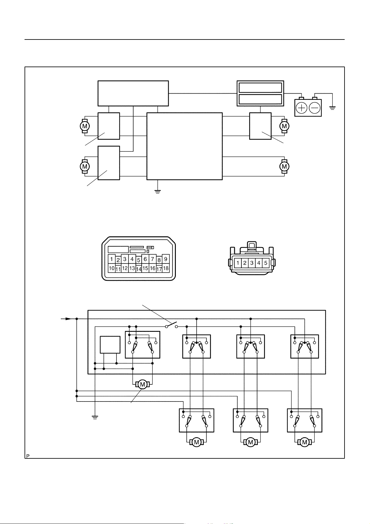
System Drawing
Rear Right
Regulator SW
Front Passenger’s
Regulator SW
Center J/B
Power Window
Master SW
Ground
Power Window Master SW Connector
(Wire Harness Side)
Instrument Panel J/B
P/W Relay
Battery
Gauge Fuse
Rear Left
Regulator SW
Driver’s
Power Window
Motor
Power Window Regulator SW Connector
(Wire Harness Side)
Switch Inner Circuit
Window Lock Switch
From
Battery
6
7
3151
Ground
IC
4
Driver’s
Power Window
Motor
Front Passenger’s
Regulator SW
Power Window Master SW
9
18
4
52
31
Rear Left
Regulator SW
12
3
13 10
54
2
1
4
5
3
Rear Right
Regulator SW
16
2
1
B59862
2004 COROLLA (RM1037U)
1739Author: Date:
Page 2
–WINDSHIELD/WINDOWGLASS/MIRROR POWER WINDOW CONTROL SYSTEM
70–5
Master
Switch
Window
Lock Switch
B59314
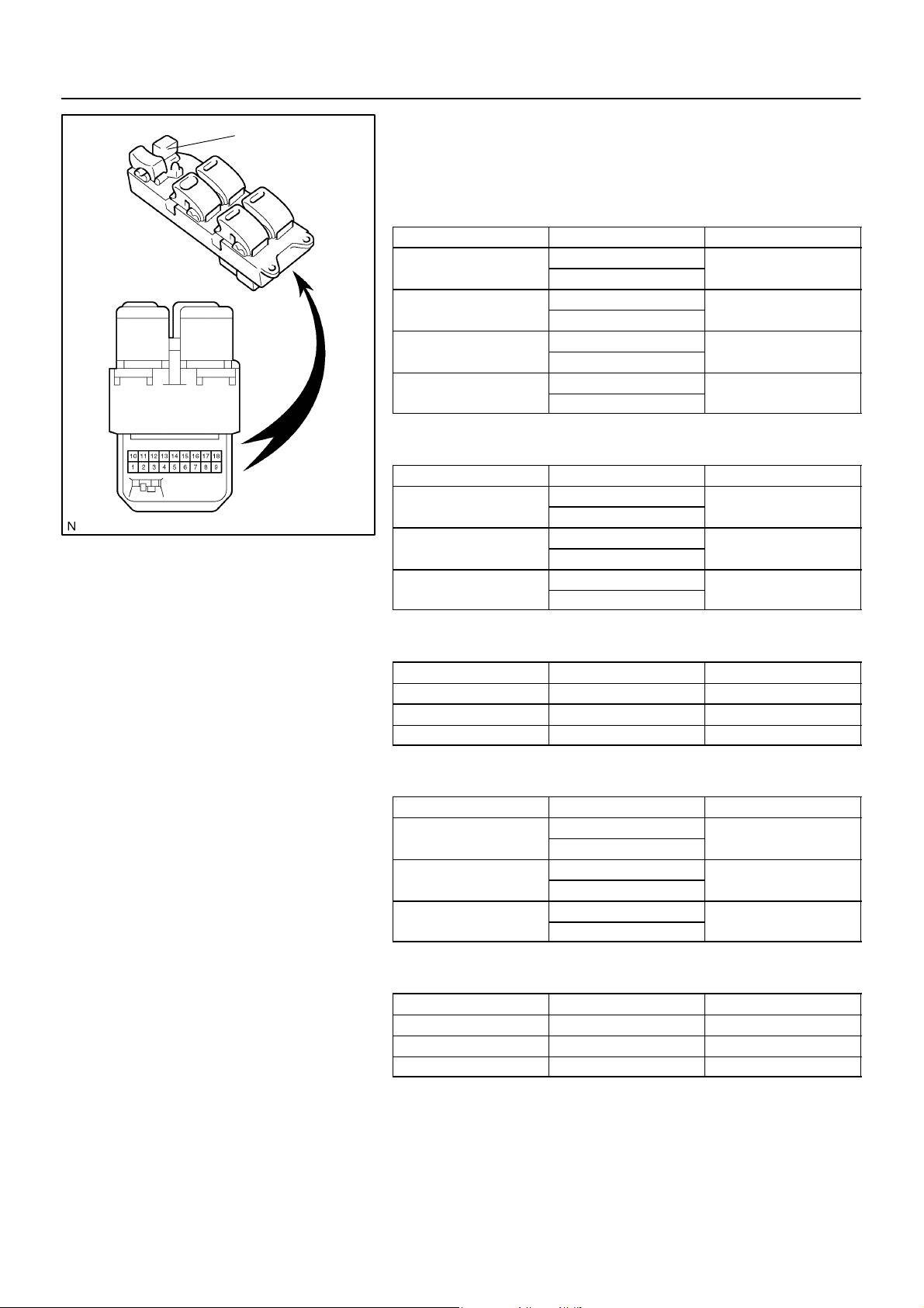
2. INSPECT POWER WINDOW REGULATOR MASTER
SWITCH ASSY
(a) Inspect the master switch continuity.
[Driver ’s switch (Window unlock and lock)]
Standard:
Switch position Symbols (Terminal No.) Specified condition
UP
OFF
DOWN
AUTO DOWN
DU (4) ⇔ B (6) ⇔ B (7)
E (1) ⇔ E (3) ⇔ DD (9)
E (1) ⇔ E (3) ⇔ DU (4)
E (1) ⇔ E (3) ⇔ DD (9)
E (1) ⇔ E (3) ⇔ DU (4)
B (6) ⇔ B (7) ⇔ DD (9)
E (1) ⇔ E (3) ⇔ DU (4)
B (6) ⇔ B (7) ⇔ DD (9)
Continuity
Continuity
Continuity
Continuity
[Front passenger ’s switch (Window unlock)]
Standard:
Switch position Symbols (Terminal No.) Specified condition
UP
OFF
DOWN
E (1) ⇔ E (3) ⇔PD (15)
B (6) ⇔ B (7) ⇔ PU (18)
E (1) ⇔ E (3) ⇔ PD (15)
E (1) ⇔ E (3) ⇔ PU (18)
E (1) ⇔ E (3) ⇔ PU (18)
B (6) ⇔ B (7) ⇔ PD (15)
Continuity
Continuity
Continuity
[Front passenger ’s switch (Window lock)]
Standard:
Switch position Symbols (Terminal No.) Specified condition
UP B (6) ⇔ B (7) ⇔ PU (18) Continuity
OFF PD (15) ⇔ PU (18) Continuity
DOWN B (6) ⇔ B (7) ⇔ PD (15) Continuity
[Rear left switch (Window unlock)]
Standard:
Switch position Symbols (Terminal No.) Specified condition
UP
OFF
DOWN
E (1) ⇔ E (3) ⇔ RLD (13)
B (6) ⇔ B (7) ⇔ RLU (12)
E (1) ⇔ E (3) ⇔ RLD (13)
E (1) ⇔ E (3) ⇔ RLU (12)
E (1) ⇔ E (3) ⇔ RLU (12)
B (6) ⇔ B (7) ⇔ RLD (13)
Continuity
Continuity
Continuity
[Rear left switch (Window lock)]
Standard:
Switch position Symbols (Terminal No.) Specified condition
UP B (6) ⇔ B (7) ⇔ RLU (12) Continuity
OFF RLU (12) ⇔ RLD (13) Continuity
DOWN B (6) ⇔ B (7) ⇔ RLD (13) Continuity
2004 COROLLA (RM1037U)
1740Author: Date:
Page 3

70–6
Battery ositive (+) Terminal 6
–WINDSHIELD/WINDOWGLASS/MIRROR POWER WINDOW CONTROL SYSTEM
[Rear right switch (Window unlock)]
Standard:
Switch position Symbols (Terminal No.) Specified condition
B (6) ⇔ B (7)
UP
OFF
DOWN
⇔ RRU (10)
E (1) ⇔ E (3)
⇔ RRD (16)
E (1) ⇔ E (3)
⇔ RRU (10)
E (1) ⇔ E (3)
⇔ RRD (16)
E (1) ⇔ E (3)
⇔ RRU (10)
B (6) ⇔ B (7)
⇔ RRD (16)
Continuity
Continuity
Continuity
[Rear right switch (Window lock)]
Standard:
Switch position Symbols (Terminal No.) Specified condition
UP
OFF RRU (10) ⇔ RRD (16) Continuity
DOWN
B (6) ⇔ B (7)
⇔ RRU (10)
B (6) ⇔ B (7)
⇔ RRD (16)
Continuity
Continuity
If the result is not as specified, replace the master switch.
Master Switch
3
6
Battery
Regulator Switch
2004 COROLLA (RM1037U)
Illumination
12345
B59315
B59316
(b) Inspect the master switch illumination.
Standard:
Measuring condition Specified condition
Battery positive (+) Terminal – 6
Battery negative (–) Terminal – 3
Switch illumination lights up
p
If the result is not as specified, replace the master switch.
3. INSPECT POWER WINDOW REGULATOR SWITCH
ASSY
HINT:
All the regulator switches (front passenger’s, rear left, rear right)
should be inspected in the same procedure.
(a) Inspect the regulator switch continuity.
Standard:
Switch position Symbols (Terminal No.) Specified condition
UP
OFF
DOWN
D (1) ⇔ SD (2)
U (3) ⇔ B (4)
D (1) ⇔ SD (2)
U (3) ⇔ SU (5)
D (1) ⇔ B (4)
U (3) ⇔ SU (5)
Continuity
Continuity
Continuity
If the result is not as specified, replace the regulator switch.
1741Author: Date:
Page 4

–WINDSHIELD/WINDOWGLASS/MIRROR POWER WINDOW CONTROL SYSTEM
70–7
Driver’s Side
Rear RH Side
Driving
Axis
Front Passenger’s Side
Rear LH Side
Clockwise
Counterclockwise
Counterclockwise
Clockwise
Driving Axis
B59875
4. INSPECT POWER WINDOW REGULATOR MOTOR
(a) Inspect the regulator motor operation.
HINT:
Driver’s side and rear RH regulator motors should be in-
spected in the same procedure.
Passenger’s side and rear LH regulator motors should be
inspected in the same procedure.
(1) Check that the motor operates smoothly when the
battery positive voltage is applied to each terminal
of the connector.
Standard [Driver ’s side and rear RH side]:
Measuring condition Operational direction
Battery positive (+) Terminal – 4
Battery negative (–) Terminal – 5
Battery positive (+) Terminal – 5
Battery negative (–) Terminal – 4
Clockwise toward driving axis
Counterclockwise toward driving axis
Standard [Front passenger’s side and rear LH side]:
Measuring condition Operational direction
Battery positive (+) Terminal – 5
Battery negative (–) Terminal – 4
Battery positive (+) Terminal – 4
Battery negative (–) Terminal – 5
Clockwise toward driving axis
Counterclockwise toward driving axis
If the result is not as specified, replace the motor.
Fully Closed Position
(b) Inspect the PTC operation inside the regulator motor.
NOTICE:
The inspection should be performed with the power window regulator and door glass installed to the vehicle.
(1) Set a DC 400 A probe of the T OYOTA electrical tes-
45
ter in the wire harness of terminal 4 or 5.
NOTICE:
Match the arrow mark of the probe with the current direc-
B59333
tion.
(2) Set the door glass in the fully closed position.
(3) When 60 seconds have elapsed after the door
glass is fully closed, check how long it takes for the
current to change from approximately 16 – 34 A into
1 A or less when the power window switch is turned
UP once again.
Standard: Approximately 4 – 90 seconds
2004 COROLLA (RM1037U)
1742Author: Date:
Page 5

70–8
–WINDSHIELD/WINDOWGLASS/MIRROR POWER WINDOW CONTROL SYSTEM
(4) When approximately 60 seconds have elapsed af-
ter the inspection of the current cut–off, check that
the door glass goes down when the power window
regulator switch is turned DOWN.
If the result is not as specified, replace the motor.
45
B59332
5. INSPECT RELAY (Making: P/W)
(a) Remove the power window relay from the instrument pan-
el J/B.
(b) Inspect the power window relay.
Condition Terminal No. Specified condition
Constant 1 ⇔ 2 Continuity
B16200
Apply B+ between
Terminals 1 and 2
If the result is not as specified, replace the relay.
3 ⇔ 5 Continuity
2004 COROLLA (RM1037U)
1743Author: Date:
 Loading...