


Toyota Corolla 2004 DIAGNOSTICS – SFI SYSTEM
05–44
–DIAGNOSTICS SFI SYSTEM (April, 2003)
05AIH–06
DTC P0010 CAMSHAFT POSITION ”A” ACTUATOR
CIRCUIT (BANK 1)
CIRCUIT DESCRIPTION
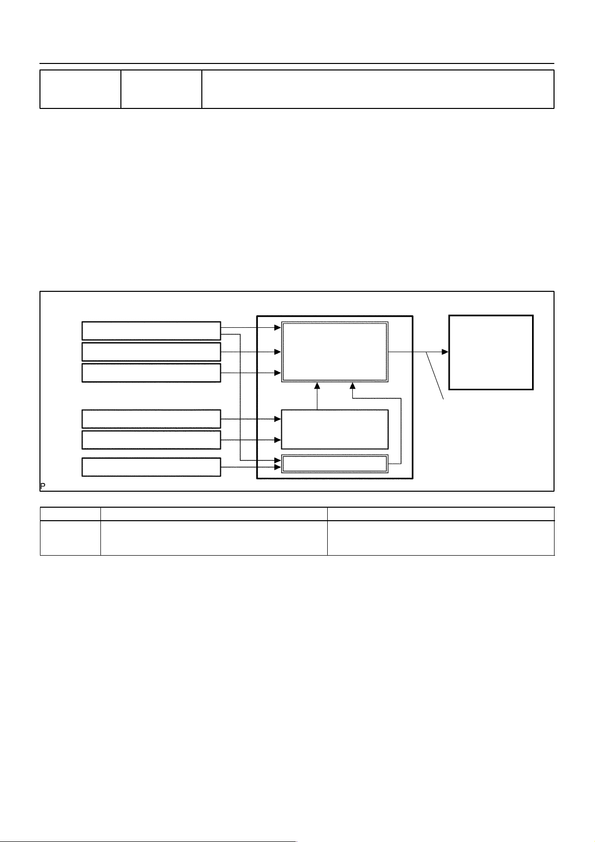
The Variable Valve Timing (VVT) system includes the ECM, the Oil Control Valve (OCV) and the VVT controller. The ECM sends a target ”duty–cycle” control signal to the OCV. This control signal, applied to the OCV,
regulates the oil pressure supplied to the VVT controller . Camshaft timing control is performed based on engine operation conditions such as the intake air volume, throttle position and engine coolant temperature.
The ECM controls the OCV, based on the signals output from the sensors. The VVT controller regulates the
intake camshaft angle using oil pressure through the OCV. As result, the relative position between the camshaft and the crankshaft is optimized, and the engine torque improves, fuel economy improves, and exhaust
emissions decrease under overall driving conditions. Also, the ECM detects the actual valve timing using
signals from the camshaft position sensor and the crankshaft position sensor, and performs the feedback
control. This is how target valve timing is verified by the ECM.
ECM
Crankshaft Position Sensor
Mass Air Flow Sensor
Throttle Position Sensor
Engine Coolant Temp. Sensor
Vehicle Speed Signal
Camshaft Position Sensor
DTC No. DTC Detection Condition Trouble Area
P0010 Open or short in oil control valve circuit
Target Valve Timing
Feedback
Correction
Actual Valve Timing
Open or short in oil control valve circuit
Oil control valve
ECM
Camshaft Timing
Oil Control
Valve (OCV)
Duty Control
A71007
2004 COROLLA (RM1037U)
209Author: Date:

05–45
–DIAGNOSTICS SFI SYSTEM (April, 2003)
MONIT OR DESCRIPTION
After the ECM sends the ”target” duty–cycle signal to the OCV, the ECM monitors the OCV current to establish an ”actual” duty–cycle. The ECM detects a malfunction and sets a DTC when the actual duty–cycle ratio
varies from the target duty–cycle ratio.
MONIT OR STRATEGY
Related DTCs P0010 VVT oil control valve bank 1 range check
Required sensors/components OCV
Frequency of operation Continuous
Duration 1 seconds
MIL operation Immediately
Sequence of operation None
TYPICAL ENABLING CONDITIONS
Item
The monitor will run whenever the following DTCs are not present
Battery voltage 11 V 13 V
Target duty ratio – 70 %
Starter OFF
Current cut status Not cut
Minimum Maximum
See ”List of Disable a Monitor” (On page 05–25)
Specification
TYPICAL MALFUNCTION THRESHOLDS
Detection Criteria Threshold
One of the following condition is met: (a) or (b)
(a) Output signal duty for OCV
(b) Output signal duty for OCV
Output duty ratio is 100 % (always ON)
despite the target duty ratio is less than 70 %
Output duty is 3 % or less
despite the ECM supplying the current to the OCV
COMPONENT OPERATING RANGE
Parameter Standard Value
Output signal duty for OCV Between 3 % and 100 %
2004 COROLLA (RM1037U)
210Author: Date: