

Toyota Corolla 2004 DIAGNOSTICS – POWER DOOR LOCK CONTROL SYSTEM
05–682
–DIAGNOSTICS POWER DOOR LOCK CONTROL SYSTEM
057TJ–01
KEY CONFINEMENT PREVENTION FUNCTION DOES NOT WORK
PROPERLY (UNLOCK WARNING SWITCH CIRCUIT)
CIRCUIT DESCRIPTION
The unlock warning switch turns on when the key is inserted in the ignition key cylinder and the door courtesy
switch turn s o n when the driver’s door is opened, and the integration relay monitors both switches conditions.
According to these switches conditions, the integration relay controls the door locking operation not to lock
the doors while both switches are on, in order to prevent the key from being confined.
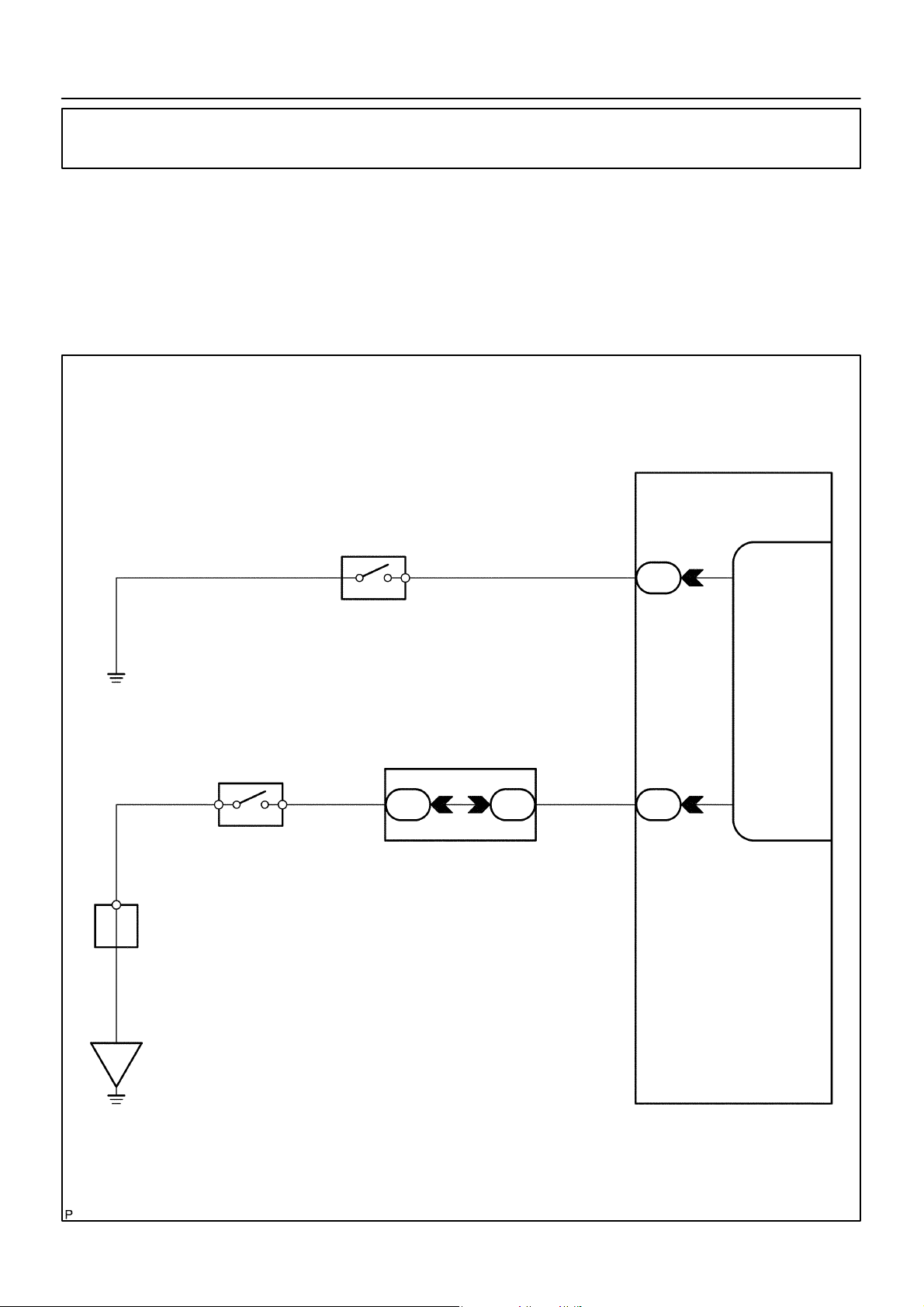
WIRING DIAGRAM
Instrument Panel J/B
D4
Front Door Courtesy Lamp Switch Assy
(Driver’s Side)
1
U1
Un–lock Warning Switch Assy
W–B
A
J6
J/C
12
L–B
*1
Center J/B
15
4A 4A
R–W
16
L–B
1
ID
8
IJ
I11
Integration Relay
5
DCTY
4
KSW
IE
2004 COROLLA (RM1037U)
*1: w/ Door Lock Control
B59535
847Author: Date:
–DIAGNOSTICS POWER DOOR LOCK CONTROL SYSTEM
INSPECTION PROCEDURE
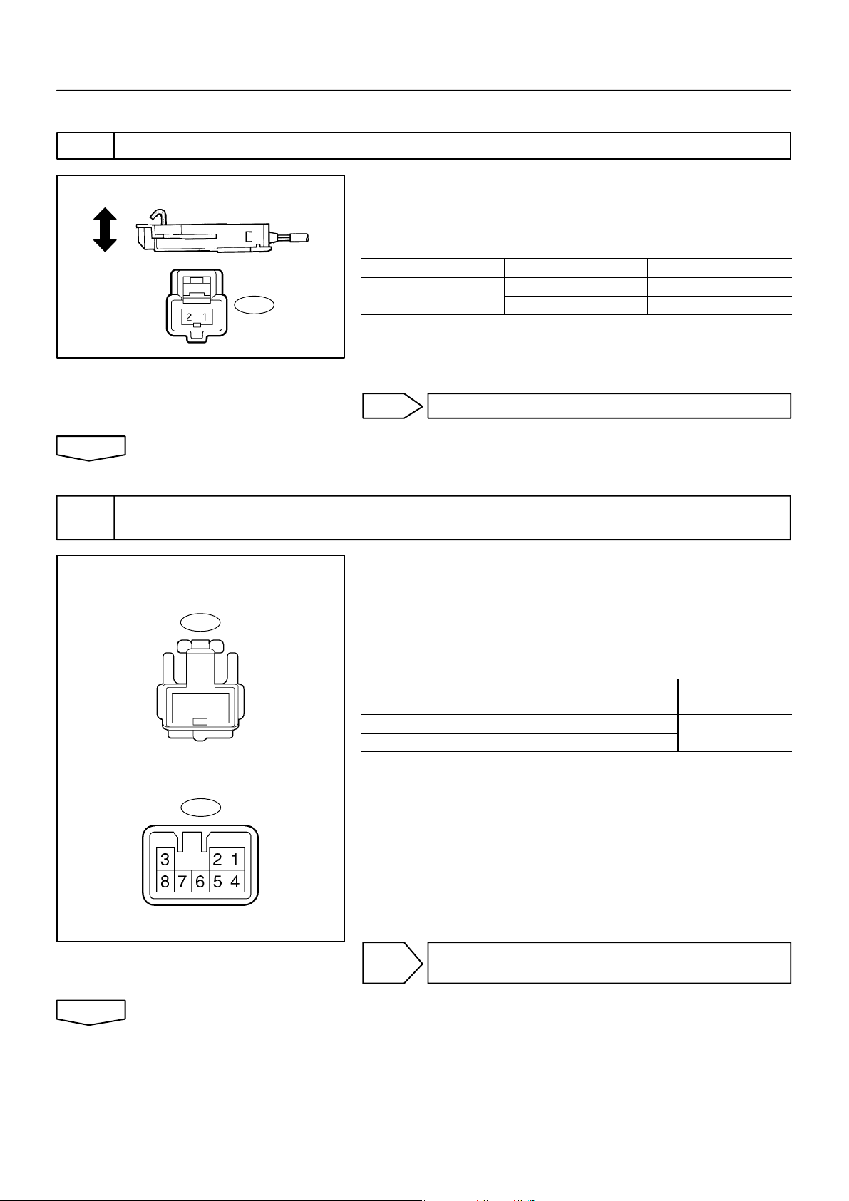
1 INSPECT UN–LOCK WARNING SWITCH ASSY
05–683
Un–lock Warning Switch Assy
Free
Push
U1
OK
2 CHECK WIRE HARNESS
(UN–LOCK WARNING SWITCH ⇔ INSTRUMENT PANEL J/B)
Un–lock W arning Switch Assy
(Wire Harness Side)
U1
21
B51903
(a) Remove the un–lock warning switch assy.
(b) Inspect the un–lock warning switch assy continuity, as
shown in the illustration and table.
Standard:
Terminal No. Condition Specified condition
U1–1 ⇔ U1–2
Free No continuity
Push Continuity
NG REPLACE UN–LOCK WARNING SWITCH ASSY
(a) Disconnect the un–lock warning switch assy and instru-
ment panel J/B connectors.
(b) Check the continuity between the terminals of the un–lock
warning switch assy and instrument panel J/B connectors, as shown in the illustration and table.
Standard (Check for open):
Symbols (Terminal No.)
(Un–lock warning switch ⇔ Instrument panel J/B)
(U1–2) ⇔ KSW (IJ–8)
(U1–1) ⇔ Body ground
Specified condition
Continuity
Instrument Panel J/B
(Wire Harness Side)
IJ
OK
2004 COROLLA (RM1037U)
B59536
NG REPAIR OR REPLACE WIRE HARNESS AND
CONNECTOR
848Author: Date:
 Loading...