

Toyota Corolla 2004 Electrical Wiring Diagram - Multiplex Communication System – CAN
Multiplex Communication System – CAN
)
S 1(A
Skid Control ECU
with Actuator
D 1
Data Link
Connector 3
CANL CANH
A25 A11
W
W
EB EB
W
B
B
IA77IA718
B
J11
Junction
Connector
14
CANHCANL
6
W
W
B
BEBE
B
174
910 2 3
CANHCANLCANHCANL
S12
Steering Sensor
COROLLA (EM00H0U)
Y 1
Yaw Rate Sensor
S1
A
:
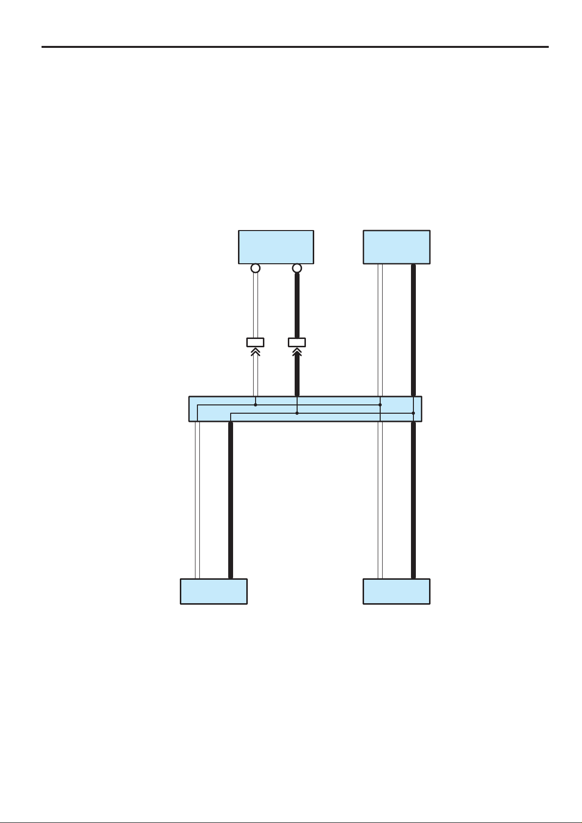
System Outline
Multiplex communication system (CAN) uses a serial communication protocol and communicates with a differential voltage.
In this network system, TERMINALS CANH and CANL are used for communication between the ECUs and sensors, and
excellent data communication speed and communication error detecting facility are provided.
This system is working for the following systems:
∗ ABS (w/ VSC)
∗ TRAC
∗ VSC
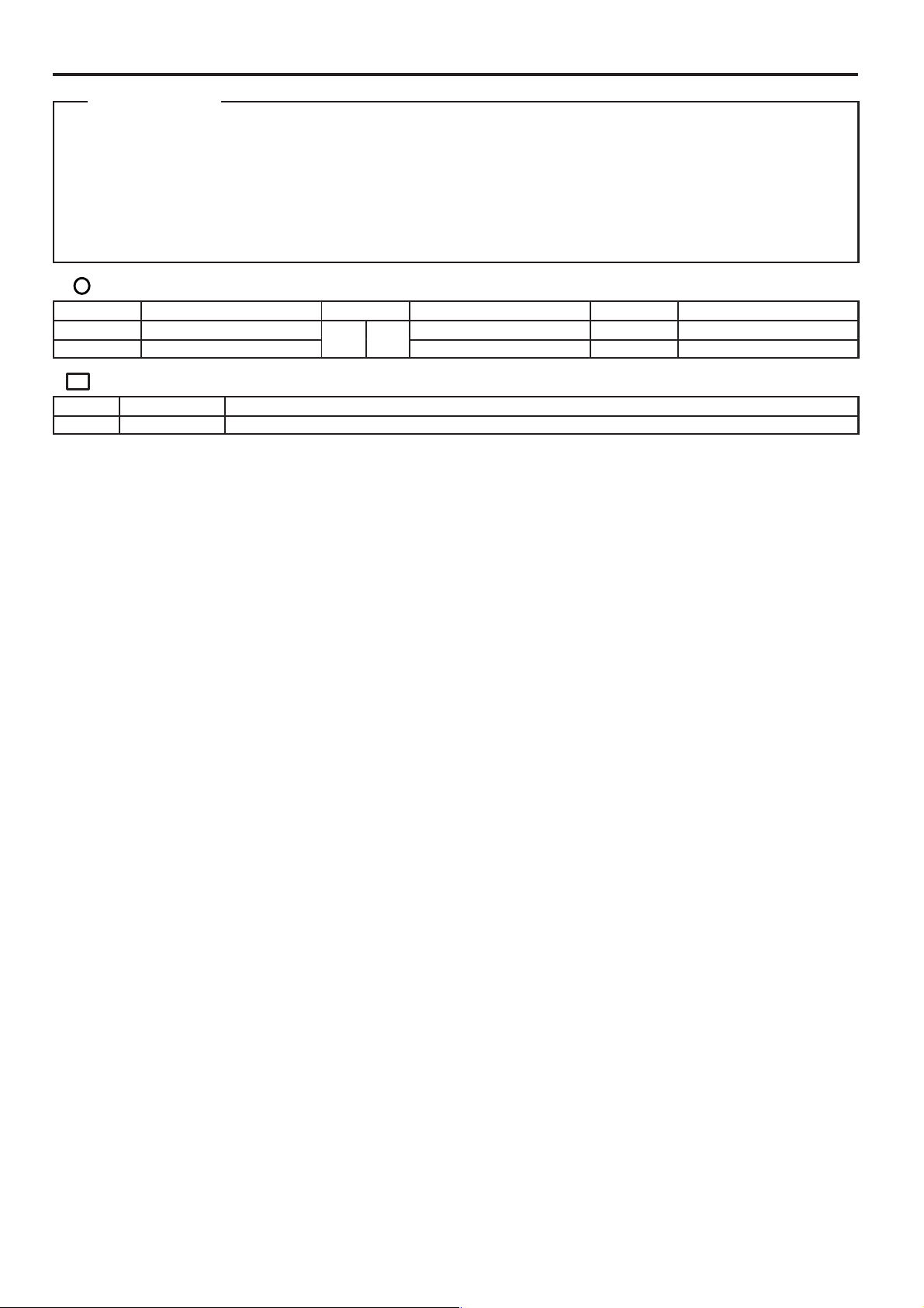
: Parts Location
Code See Page Code See Page Code See Page
D1 36
J11 37
Connector Joining Wire Harness and Wire Harness
Code See Page Joining Wire Harness and Wire Harness (Connector Location)
IA7 44 Engine Room Main Wire and Instrument Panel Wire (Left Side of the Instrument Panel Reinforcement)
33 (1ZZ–FE) S12 37
35 (2ZZ–GE) Y1 37
175
COROLLA (EM00H0U)
 Loading...