

Toyota Corolla 2004 Electrical Wiring Diagram - ABS, TRAC, VSC and Tire Pressure Warning System
Page 1
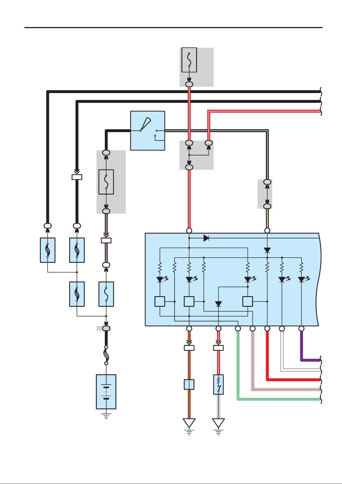
ABS, TRAC, VSC and Tire Pressure Warning System
(IG)
10A
GAUGE
IG2
R–W
B
5
IM6
B
EB11
50A
ABS
NO. 2
B
11
2
30A
ABS
NO. 1
B
2
15A
AM2
IM3
IA42
B–R B–RB
I10
Ignition SW
6AM2 IG2
ST2
B–W
3B22
3B16
R–W
20 3B
C 9(A), C16(B
Combination Meter
B–W
IL5
IK8
B–O
)
32 A4A
B
B
R–W
1
1
2
100A
ALT
1
1
2
Tire Pressure
30A
MAIN
1
1A1
FL
MAIN
2. 0L
Battery
J 3
ABS
5 II2
C
Junction
Connector
C
BR
BR
BR
B 2
Brake Fluid Level
Brake
29 A
R–W
IA517
1
Warning SW
2
W–B R–W
EDEB
Slip
36 A37 A35 A1A
VSC
B2
B3
V
W
R
W–R
LG
166
COROLLA (EM00H0U)
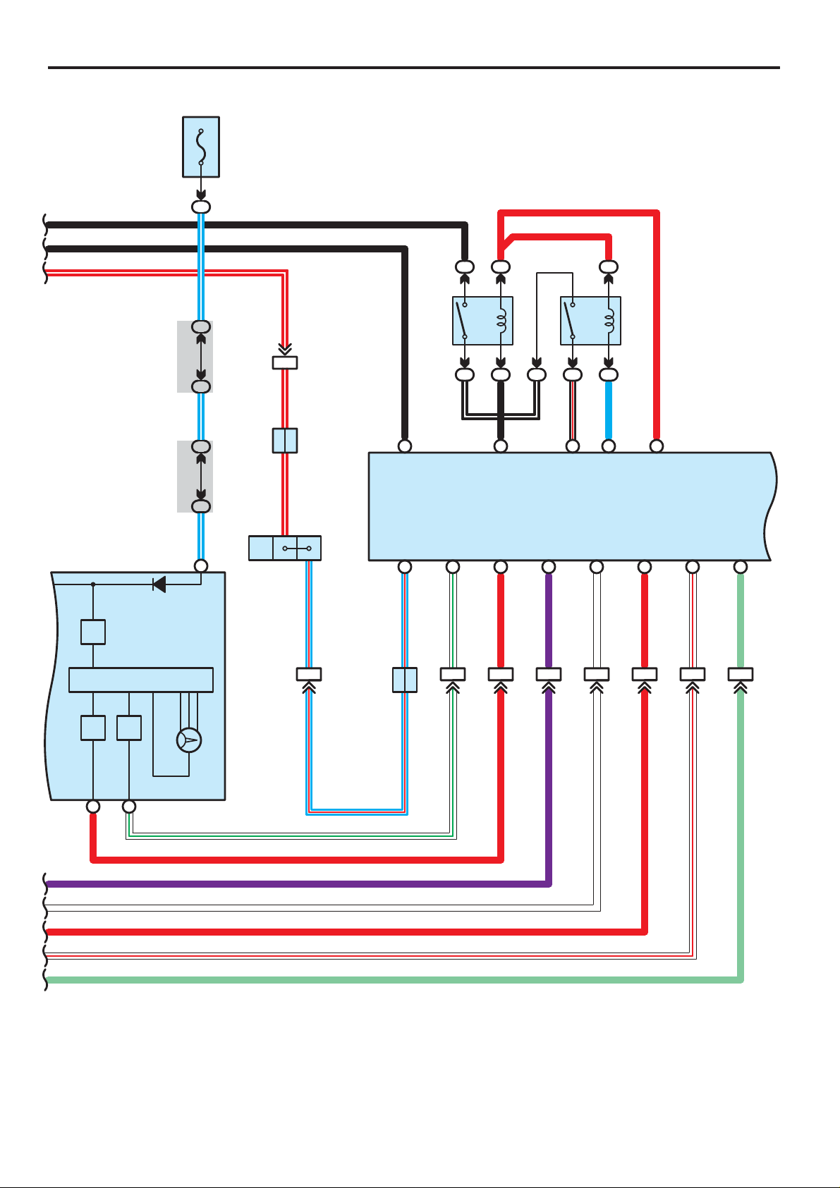
Page 2
B
B
R–W
(
BAT
2
)
15A
DOME
1
B
22
2
R–W
IC7
II214
IL4
B
B
ABS MTR CUT Relay
22 22
B
B–W
R
R
1515
3223
2
B–R
ABS MTR Relay
L
R
V
W
R
W–R
LG
38 A
9A
W–G
R
Speedometer
4C20
4C19
L–W L–W L–W
5A
)
B
(
, C16
)
A
(
C 9
Combination Meter
PL
Junction
Connector
J 4
B
R–W R–W
2
A 2
A/T Shift Lever
6
EA17
L–R L–R
Position SW
A31 A14 A2A15 A45
+BS MRF
)
S 1(A
Skid Control ECU with Actuator
P
A40 A12 A7A36 A34 A44 A29 A26
L–R
D
Junction
Connector
J 1
D
L–R
SP1 BRL WA
W–G
14 IA6 IA516 IA65
W–G
TSI
R
5IA5
R
V
2IA7
V
BM
13 IA7
MR
INDVSCW
W
W
R+
R
R
W–R
W–R
WTIR
LG
IA514
LG
COROLLA (EM00H0U)
167
Page 3
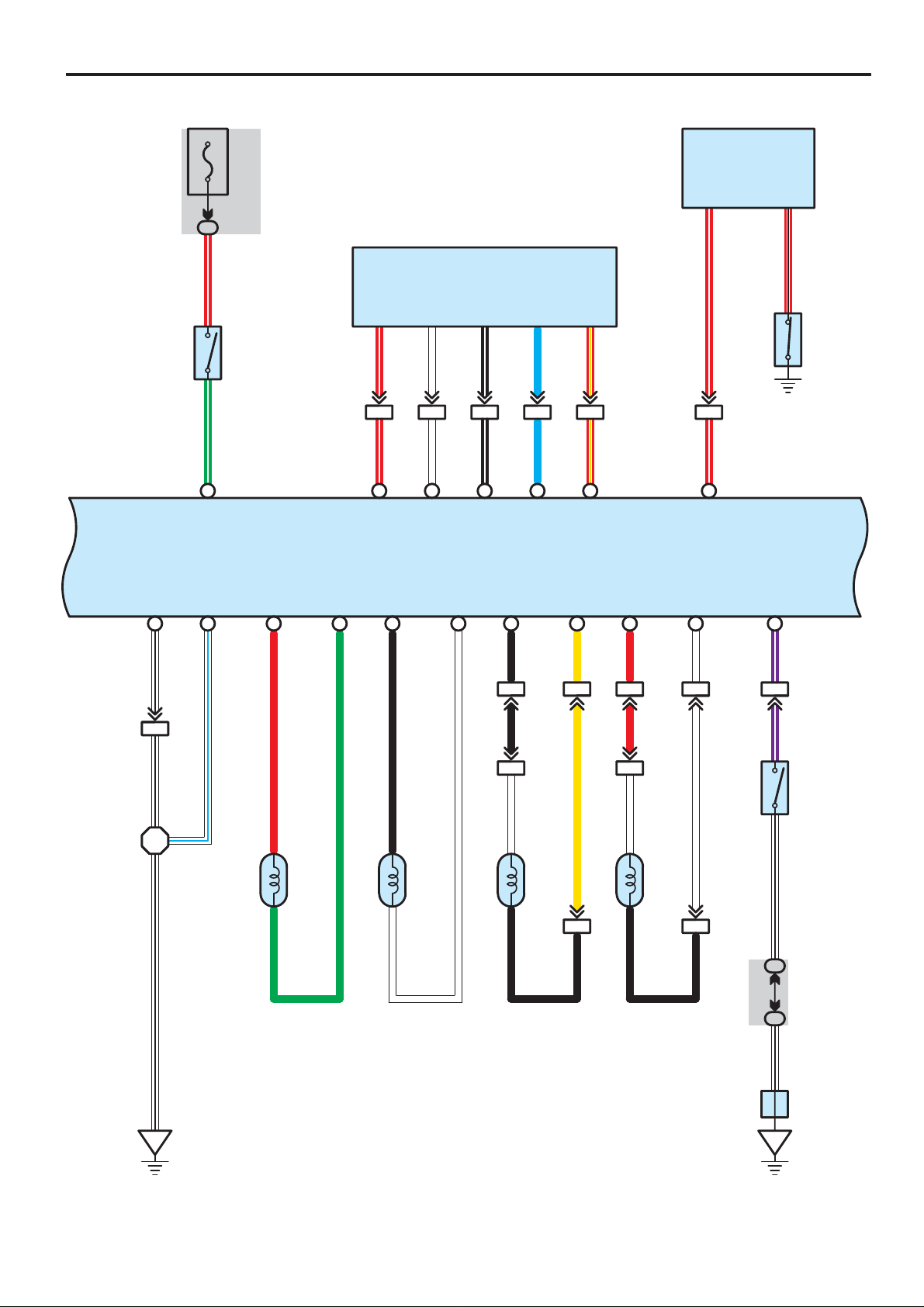
ABS, TRAC, VSC and Tire Pressure Warning System
(
)
BAT
15A
STOP
IC
14
E 6
Engine Control Module
D 2
Daytime Running Light
Relay
BRK PKB
10 11
R–B
R–WG–W
2
S 9
Stop
Light
SW
1
A27 A8A22 A9A23 A10 A28
STP PKB
GND1 GND2 FL+ FL– FR+ FR– RL+ RL– RR+ RR–
A32 A1A18 A4A3A17 A20 A6A5A19 A41
W–B
4 EB1
W–L
R
VSC+
25 31
IA76
TRC+
G
R–WR–W
B
VSC–
17 IA7 IA75
TRC–
ENG+ NEO
24
WW
ENG+
W
ENG–
30
B–WB–W
16 4 IA7IA7
LL
ENG–
B
1IB1
B
BC11BD11
17
R–Y R–Y
NEO
Y
IB12IB13IB14
R
R
R–WR–W
IA515
W
1
)
S 1(A
Skid Control ECU
with Actuator
INIT
V–WV–WW–BW–B
IA510
8
P 3
Parking Brake SW
168
W–B
W–B
EA
W
2
ABS Speed Sensor
Front LH
A 3
1
2
ABS Speed Sensor
Front RH
A 4
1
2
1
B
Y
ABS Speed Sensor
Rear LH
A19
BC12BD12
W
2
1
B
A20
ABS Speed Sensor
Rear RH
W
14 4B
21 4B
5
A
IE
T 7
Tire Pressure Warning
Standardization SW
J 6
Junction
Connector
COROLLA (EM00H0U)
Page 4

(IG) (
D 1
10A
ECU–IG
Data Link Connector 3
BAT
)
10A
ECU–B
B–W
IC13
B–WB–W
EB12
A46 A30 A24 A42 A13
IG1 TS WFSE D/G
)
S 1(A
Skid Control ECU
with Actuator
IF9
B–W
3B5
63B
2
B–W B–W
1
CSW CANL CANH
A43 A25 A11
R–Y
V 6
IA715
B–O Y–B
BZ
TS WFSE SIL
12 15 7
P
VSC Warning Buzzer
11 IA6 IA714 4 IA6
GR GR
P
W
L–R
23B
3B1
L–R
L–R
EB13
L–R
B
CANHCANL
6
14
B
W
IH1
R–B
IA73
R–Y
9
6
W–B
W–B
22 3A
11 3A
W–B
A
IG
T 8
Traction Off SW
W–B
J 7
Junction
Connector
IA77IA718
J11
Junction
Connector
E
B
W
910 3
CANL CANH BAT IG1 CANL CANH IG
ESS GND
21
W–B
W
E
R–B
B
B
B–W
12
S12
Steering Sensor
B
W
EB
BEB
B
W
35
W–B
B–W
B–W
Y 1
Yaw Rate Sensor
COROLLA (EM00H0U)
169
Page 5

ABS, TRAC, VSC and Tire Pressure Warning System
System Outline
1. ABS Operation
If the brake pedal is depressed suddenly, the ABS controls the hydraulic pressure of the wheel cylinders for all the four
wheels to automatically avoid wheel locking and ensure the directional and steering stability of the vehicle. If the brake pedal
is depressed suddenly, the skid control ECU controls the solenoids in the actuators using the signals from the sensors to
move the brake fluid to the reservoir in order to release the braking pressure applied to the wheel cylinder. If the skid control
ECU detects that the fluid pressure in the wheel cylinder is insufficient, the ECU controls the solenoids in the actuators to
increase the braking pressure.
2. T raction Control Operation
The traction control system controls the engine torque, the hydraulic pressure of the driving wheel cylinders, slipping of the
wheels which may occur at start or acceleration of the vehicle, to ensure an optimal driving power and vehicle stability
corresponding to the road conditions.
3. VSC Operation
Unexpected road conditions, vehicle speed, emergency situation, and any other external factors may cause large under– or
over–steering of the vehicle. If this occurs, the VSC system automatically controls the engine power and wheel brakes to
reduce the under– or over–steering.
To reduce large over–steering :
If the VSC system determines that the over–steering is large, it activates the brakes for the outer turning wheels depending
on the degree of the over–steering to produce the moment toward the outside of the vehicle and reduce the over–steering.
To reduce large under–steering :
If the VSC system determines that the under–steering is large, it controls the engine power and activates the rear wheel
brakes to reduce the under–steering.
Traction off SW
The traction off SW is used to stop the TRAC function. After the engine is started, the TRAC system is stopped (Turned off)
and the traction off indicator light lights up. When the traction off SW is pressed again, the TRAC system enters the stand–by
mode. If the engine is stopped and restarted, the TRAC system enters the stand–by mode regardless of the traction off SW.
VSC indicator light
If an error occurs in the VSC system, the VSC indicator lights up to warn the driver.
4. Mutual System Control
To efficiently operate the VSC system at its optimal level, the VSC system and other control systems are mutually controlled
while the VSC system is being operated.
Engine fuel injecting control
The engine power does not interfere with the VSC brake control by controlling the opening of the fuel injecting and reducing
the engine output.
Engine control and electronically controlled transmission control
The strong engine braking force does not interfere with the braking force control of the VSC system by turning off the accel.
and reducing changes in the driving torque at shift–down.
VSC system operation indication
The slip indicator light flashes and the buzzer sounds intermittently to warn the driver that the current road is slippery, while
the VSC system is being operated.
5. Fail Safe Function
If an error occurs in the skid control ECU, sensor signals, and/or actuators, the skid control ECU inhibits the brake actuator
control and inputs the error signal to the engine control module. According to the error signal, the brake actuator turns off the
solenoid and the engine control module rejects any electronically controlled fuel injection request from the VSC system. As a
result, the vehicle functions without the ABS, TRC, and VSC systems.
170
COROLLA (EM00H0U)
Page 6

: Parts Location
A3
A4
S1
A
A19
J1
A20
B2
:
:
25
25
Instrument Panel Wire and Instrument Panel J/B (Lower Finish Panel)
24
24
28
Instrument Panel Wire and RH J/B (Right Side of the Instrument Panel Reinforcement)
30
Instrument Panel Wire and Center J/B (Behind the Combination Meter)
:
EA1
Engine Wire and Engine Room Main Wire (Inside of the Engine Room R/B)
44
Engine Room Main Wire and Instrument Panel Wire (Left Side of the Instrument Panel Reinforcement)
BC1
Skid Control Sensor Wire LH and Floor Wire (Quarter Wheel House LH)
BD1
Skid Control Sensor Wire RH and Floor Wire (Quarter Wheel House RH)
Code See Page Code See Page Code See Page
A2 32 (1ZZ–FE) C9 A 36 J7 37
32 (1ZZ–FE) C16 B 36 J11 37
34 (2ZZ–GE) D1 36 P3 37
32 (1ZZ–FE) D2 36
34 (2ZZ–GE) E6 36
38 (*1) I10 37 S9 37
40 (*2)
38 (*1)
40 (*2) J3 37 T8 37
32 (1ZZ–FE) J4 37 V6 37
34 (2ZZ–GE) J6 37 Y1 37
33 (1ZZ–FE) S12 37
35 (2ZZ–GE) T7 37
33 (1ZZ–FE)
35 (2ZZ–GE)
Relay Blocks
Code See Page Relay Blocks (Relay Block Location)
1 22 Engine Room R/B (Engine Compartment Left)
2 23 ABS R/B (Engine Compartment Left)
Junction Block and Wire Harness Connector
Code See Page Junction Block and Wire Harness (Connector Location)
IC 25 Engine Room Main Wire and Instrument Panel J/B (Lower Finish Panel)
IF
IG
IH
IK
IL
IM
1A 22 Engine Wire and Engine Room J/B (Engine Compartment Left)
3A
3B
4B
4C
Connector Joining Wire Harness and Wire Harness
Code See Page Joining Wire Harness and Wire Harness (Connector Location)
42 (1ZZ–FE)
43 (2ZZ–GE)
EB1 42 (1ZZ–FE) Engine Room Main Wire and Engine Room Main Wire (Front Right Fender)
IA4
IA5
IA6
IA7
IB1 44 Engine Room Main Wire and Floor Wire (Cowl Side Panel LH)
II2 45 Engine Wire and Instrument Panel Wire (Blower Unit RH)
46 (*1)
47 (*2)
46 (*1)
47 (*2)
* 1 : w/ Side Airbag and/or Stereo Component Amplifier * 2 : w/o Side Airbag and Stereo Component Amplifier
171
COROLLA (EM00H0U)
Page 7

ABS, TRAC, VSC and Tire Pressure Warning System
:
EA
Front Right Fender
EB
Left Side of the Cylinder Head
ED
Front Left Suspension T ower
Ground Points
Code See Page Ground Points Location
42 (1ZZ–FE)
43 (2ZZ–GE)
42 (1ZZ–FE)
43 (2ZZ–GE)
42 (1ZZ–FE)
43 (2ZZ–GE)
IE 44 Behind the Combination Meter
IG 44 Right Kick Panel
172
COROLLA (EM00H0U)
Page 8

Memo
COROLLA (EM00H0U)
173
 Loading...