

Toyota Corolla 2004 Electrical Wiring Diagram - Wiper and Washer
Wiper and Washer
From Power Source Syst em (See Page 48
25A
WIPER
IC11 IL7
L
L
15A
WASHER
L
)
C11
Combination SW
IC9
)
*4
(
)
)
*2
*1
(
Wiper Relay
+B +2 +1 +S EW W
8976 54
(
* 1 : w/ Intermittent Volume SW
* 2 : w/o Intermittent Volume SW
* 3 : w/ Washer Cont inuou s
* 4 : w/ Intermittent
MIST
OFF
INT
LO
HI
Off
On
)
*3
(
Washer
Wiper SW
SW
2
M
1
L–Y
F 5
Front Washer
Motor
L
L–R
L–R
L–R
41 23
L–W
L–W
IA26IA28
IA27
L–W
L–W
L–W
M
L
B+1+2 S
L–W
W–B
W–B
L–Y
IA29
L–Y
98
EEA5W–B
F 6
Front Wiper Mot or
2004 COROLLA (EWD533U)
A
IE
J 6
Junction
Connector
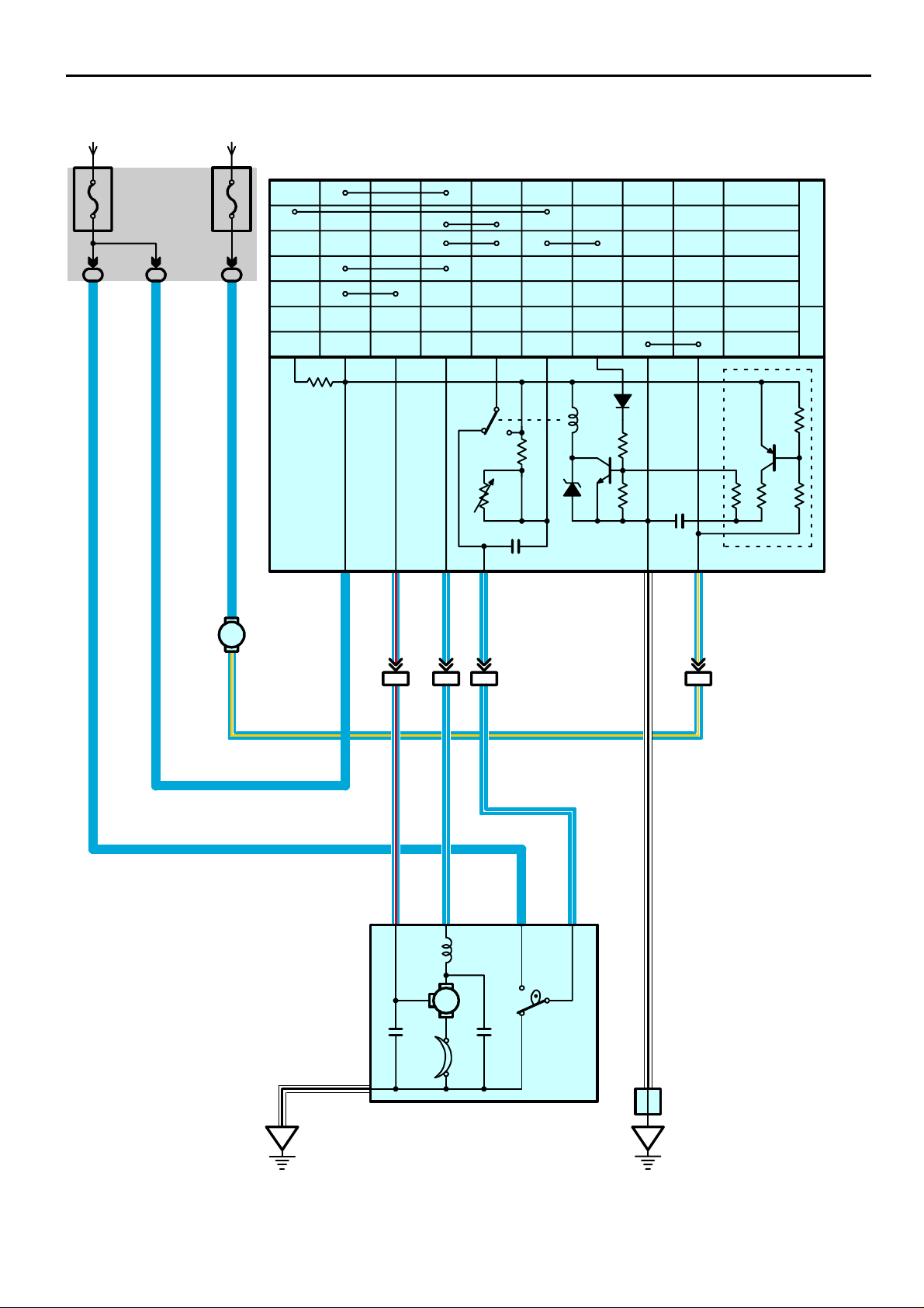
System Outline
With the ignition SW turned on, the current flows to TERMINAL 8 of the wiper and washer SW, TERMINAL 2 of the front
wiper motor through the WIPER fuse, and the current flows to TERMINAL 2 of the washer motor through the WASHER fuse.
1. Low Speed Position
With wiper SW turned to LO position, the current flows from TERMINAL 8 of the front wiper and washer SW to TERMINAL 7
to TERMINAL 1 of the front wiper motor to TERMINAL 5 to GROUND and causes to the front wiper motor to run at low
speed.
2. High Speed Position
With wiper SW turned to HI position, the current flows from TERMINAL 8 of the front wiper and washer SW to TERMINAL 9
to TERMINAL 4 of the front wiper motor to TERMINAL 5 to GROUND and causes to the wiper motor to run at high speed.
3. INT Position
With wiper SW turned to INT position, the relay operates and the current which is connected by relay function flows from
TERMINAL 8 of the front wiper and washer SW to TERMINAL 5 to GROUND. This flow of current operates the intermittent
circuit and the current flows from TERMINAL 8 of the front wiper and washer SW to TERMINAL 7 to TERMINAL 1 of the front
wiper motor to TERMINAL 5 to GROUND and the functions.
The intermittent operation is controlled by the charge/discharge function of the condenser installed in the relay, and the
intermittent time is controlled by a time control SW (w/ intermittent volume SW) to change the charging time of the
condenser.
4. MIST Position
With wiper SW turned to MIST position, the current flows from TERMINAL 8 of the front wiper and washer SW to TERMINAL
7 to TERMINAL 1 of the front wiper motor to TERMINAL 5 to GROUND and causes to the front wiper motor to run at low
speed.
5. Washer Continuous Operation
With the washer SW turned to on, the current flows from TERMINAL 2 of the washer motor to TERMINAL 1 to TERMINAL 4
of the front wiper and washer SW to TERMINAL 5 to GROUND and causes to the washer motor to run, and the window
washer jet operates. This causes the current to flow to washer continuous operation circuit in TERMINAL 8 of the front wiper
and washer SW to TERMINAL 7 to TERMINAL 1 of the front wiper motor to TERMINAL 5 to GROUND and the washer
operates continuously.
Service Hints
C11 Combination SW
5–Ground : Always continuity
8–Ground : Approx. 12 volts with ignition SW at On position
7–Ground : Approx. 12 volts with wiper and washer SW at LO position
: Approx. 12 volts with wiper and washer SW at MIST position
: Approx. 12 volts every approx. 1 to 10 seconds intermittently with wiper and washer SW at INT position
6–Ground : Approx. 12 volts with ignition SW on unless wiper motor at STOP position
9–Ground : Approx. 12 volts with ignition SW on and wiper and washer SW at HI position
F6 Front Wiper Motor
2–3 : Closed unless wiper motor at STOP position
: Parts Location
Code See Page Code See Page Code See Page
C11 34 F6 32
F5 32 J6 35
:
Junction Block and Wire Harness Connector
Code See Page Junction Block and Wire Harness (Connector Location)
IC 25 Engine Room Main Wire and Instrument Panel J/B (Lower Finish Panel)
IL 24 Instrument Panel Wire and Instrument Panel J/B (Lower Finish Panel)
:
Connector Joining Wire Harness and Wire Harness
Code See Page Joining Wire Harness and Wire Harness (Connector Location)
IA2 40 Engine Room Main Wire and Instrument Panel Wire (Left Side of the Instrument Panel Reinforcement)
2004 COROLLA (EWD533U)
99
 Loading...