

Toyota COROLLA 2004 Electrical Wiring Diagram - howtouse

HOW TO USE THIS MANUAL B
This ma n u a l p r o v i d e s i n f o r m a t ion on the electrical circuits installed on vehicles by
dividing them into a circuit for each system.
The actual wiring of each system circuit is shown from the point where the power
source is received from the battery as far as each ground point. (All circuit
diagrams are shown with the switches in the OFF position.)
When troubleshooting any problem, first understand the operation of the circuit
where the problem was detected (see System Circuit section), the power source
supplying power to that circuit (see Power Source section), and the ground points
(see Ground Point section). See the System Outline to understand the circuit
operation.
When the circuit operation is understood, begin troubleshooting of the problem
circuit to isolate the cause. Use Relay Location and Electrical Wiring Routing
sections to find each part, junction block and wiring harness connectors, wiring
harness and wiring harness connectors, splice points, and ground points of each
system circuit. Internal wiring for each junction block is also provided for better
understanding of connection within a junction block.
Wiring related to each system is indicated in each system circuit by arrows
(from__, to__). When overall connections are required, see the Overall Electrical
Wiring Diagram at the end of this manual.
2004 COROLLA (EWD533U)
3
B HOW TO USE THIS MANUAL
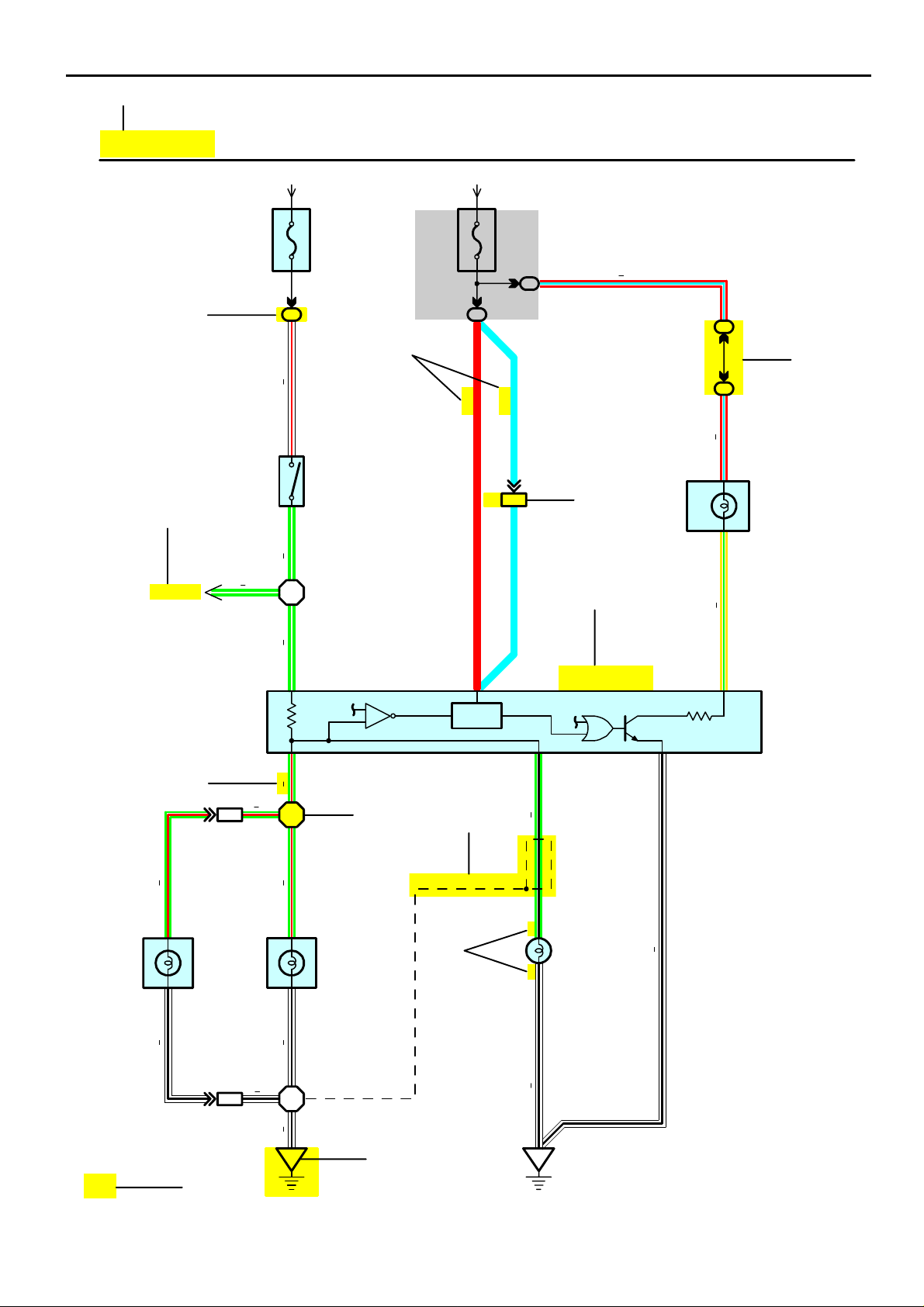
[A]
Stop Light
[B]
[D]
∗ The system shown here is an EXAMPLE ONLY. It is different to the actual
circuit shown in the SYSTEM CIRCUITS SECTION.
From Power Source System (See Page 66)
15A
STOP
2
1
7.5A
GAUGE
[C]
WRGW
2
S 6
Stop Light SW
1
4
IBIB3
RL
IB1
[G]
Rear
Lights
IB2
4
C 7
Combination
Meter
13
)
)
S/D
W/G
(
(
LL
R
IE114
[E]
ABS ECU
GR
4
Stop
3
GW
[H]
1
GR
BV1
Rear Combination Light RH
R 7
I 5
GW
2111
GR
B18
GRWBWB
3
[ I ]
[J]
(Shielded)
[K]
Stop
6
Rear Combination Light LH
R 6
)
S/D
(
8
GB
2
1
[F]
L 4
Light Failure Sensor
H17
High Mounted
Stop Light
YG RL
47
WB
4
50
WB
[M]
BV1
1
WB
B18
BO
[L]
WB
BL
2004 COROLLA (EWD533U)
B
[A] : System Title
[B] : Indicates a Relay Block. No shading is used and
only the Relay Block No. is shown to distinguish it
from the J/B
Example: Indicates Relay Block No.1
[C] : ( ) is used to indicate different wiring and
connector, etc. when the vehicle model, engine
type, or specification is different.
[D] : Indicates related system.
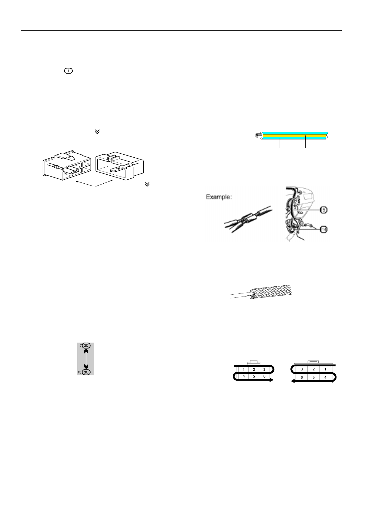
[E] : Indicates the wiring harness and wiring harness
connector. The wiring harness with male terminal is
shown with arrows ( ).
Outside numerals are pin numbers.
Female Male ( )
The first letter of the code for each wiring harness
and wiring harness connector(s) indicates the
component’s location, e.g, ”E” for the Engine
Compartment, ”I” for the Instrument Panel and
Surrounding area, and ”B” for the Body and
Surrounding area.
When more than one code has the first and second
letters in common, followed by numbers (e.g, IH1,
IH2), this indicates the same type of wiring harness
and wiring harness connector.
[F] : Represents a part (all parts are shown in sky blue).
The code is the same as the code used in parts
position.
[G] : Junction Block (The number in the circle is the J/B
No. and the connector code is shown beside it).
Junction Blocks are shaded to clearly separate
them from other parts.
Example:
3C indicates that
it is inside
Junction Block
No.3
[H] : Indicates the wiring color.
Wire colors are indicated by an alphabetical code.
B = Black W = White BR = Brown
L = Blue V = Violet SB = Sky Blue
R = Red G = Green LG = Light Green
P = Pink Y = Yellow GR= Gray
O = Orange
The first letter indicates the basic wire color and the
second letter indicates the color of the stripe.
Example: L – Y
L
(Blue)Y(Yellow)
[I] : Indicates a wiring Splice Point (Codes are ”E” for the
Engine Room, ”I” for the Instrument Panel, and ”B”
for the Body).
The Location of splice Point I 5 is indicated by the
shaded section.
[J] : Indicates a shielded cable.
[K] : Indicates the pin number of the connector.
The numbering system is different for female and
male connectors.
Example:
Numbered in order
from upper left to
lower right
Numbered in order
from upper right to
lower left
[L] : Indicates a ground point.
The first letter of the code for each ground point(s)
indicates the component’s location, e.g, ”E” for the
Engine Compartment, ”I” for the Instrument Panel
and Surrounding area, and ”B” for the Body and
Surrounding area.
[M] : Page No.
2004 COROLLA (EWD533U)
Female
Male
5
 Loading...