

Page 1

GReddy Supercharger Kit
2000-2002 Toyota Celica GT-S (ZZT231)
MP62 Supercharger kit
―1―
Page 2
SUPERCHARGER KIT
Toyota Celica ZZT231(2ZZ-GE)
Installation Manual
Please read the manual carefully before installing and using this product.
This product is for off road use only.
MAKE MODEL CHASSIS ENGINE YEAR
Toyota Celica GT-S
ZZT231
2ZZ-GE 2000 - 2002
○ For OE air cleaner or GRACER AIRINX SET.
The AIRINX SET is required
for vehicles with auto cruise control. The OE air cleaner box
will not fit on these vehicles.
○ This kit was designed for manual transmission vehicles.
The use of an air filter other than our GRACER AIRINX set with the supercharger kit may cause lean
burning conditions. Please refrain from using aftermarket intake systems other than our GRACER
AIRINX kit to prevent any possible engine damage.
This kit is designed for the vehicle specified above.
Please do not attempt to install this kit on other application.
Important
Important
1. This installation should only be performed by a trained specialist who is very
familiar with the automobile’s mechanical, electrical and fuel management
system.
2. If installed by an untrained person, it may cause damage to the kit as well as
the vehicle.
3. GReddy Performance Products Inc. is not responsible for any damage to
the vehicle’s electrical system caused by improper installation.
4 Make sure to follow the instruction and pay attention to the “Important”,
“Warning!” and “Caution!” notice through out the instruction.
5. Improper installation can be dangerous! Please make sure to inspect the
installation before operating the vehicle.
6. Call your GReddy Authorized dealer or GReddy Performance Products if
there are any problems or questions regarding this product.
―2―
Page 3

1.Parts List
1.Supercharger MP62 (W/ Pulley) 1
2.Intake Manifold 1
3.Intake Tube 1
4.Tensioner Pulley 1
5.Supercharger Belt (6PK-2475) 1
6.Alternator Bracket, Upper 1
7. 〃 Lower 1
8. 〃 Floating Nut 1
9.Oil Dip Stick Guide 1
10.Spacer, Tensioner Pulley 1
11. 〃 Alternator Bracket (20φ×15㎜) 2
12. 〃 Intake Tube Bracket (18φ×20㎜) 1
13.Bracket, Alternator Bracket 1
14. 〃 Intake Tube 1
15. 〃 Cruise Control 1set
16.Vacuum Hose 6φ×150㎜ 1
17.Cable Tie 100㎜ 5
18. 〃 200㎜ 5
19.Colgate Tube 7φ×1500㎜ 1
20.Cruise Control Extension Harness (700㎜)×4、Connectors & Sleeve (M・F)×8 1set
21.Injectors 440 cc (W/ Harness Coupler) 4
22.e-manage Ultimate US-ZZT231 1
23. 〃 Harness [Connectors & Sleeve (M・F)×21 /Splice Connector×7] 1 set
24.M6×15㎜ P1.0 Stainless B S/W ― ― (Cruise Control Bracket) 2
25.M8×15㎜ P1.25 Stainless B S/W ― ― (Alternator Bracket) 2
26.M8×25㎜ P1.25 Stainless B S/W ― ― (Intake Tube, Alternator Bracket) 4
27.M8×30㎜ P1.25 Stainless Stud B S/W ― N (Charger OUT) 6
28.M8×38㎜ P1.25 Stainless Stud B S/W ― N (Intake Manifold) 5
29.M8×50㎜ P1.25 Stainless B S/W ― ― (Intake Tube Bracket) 1
30.M8×90㎜ P1.25 Stainless B S/W ― ― (Alternator Bracket, Engine Side) 2
31.M10×25㎜ P1.25 Stainless B S/W ― ― (Intake Tube Bracket, Engine Side) 1
31.M10×70㎜ P1.25 Steel Bolt B S/W F/W ― (Alternator Bracket) 1
32.M12×70㎜ P1.5 Steel Bolt B ― ― ― (Tensioner Pulley) 1
―3―
Page 4
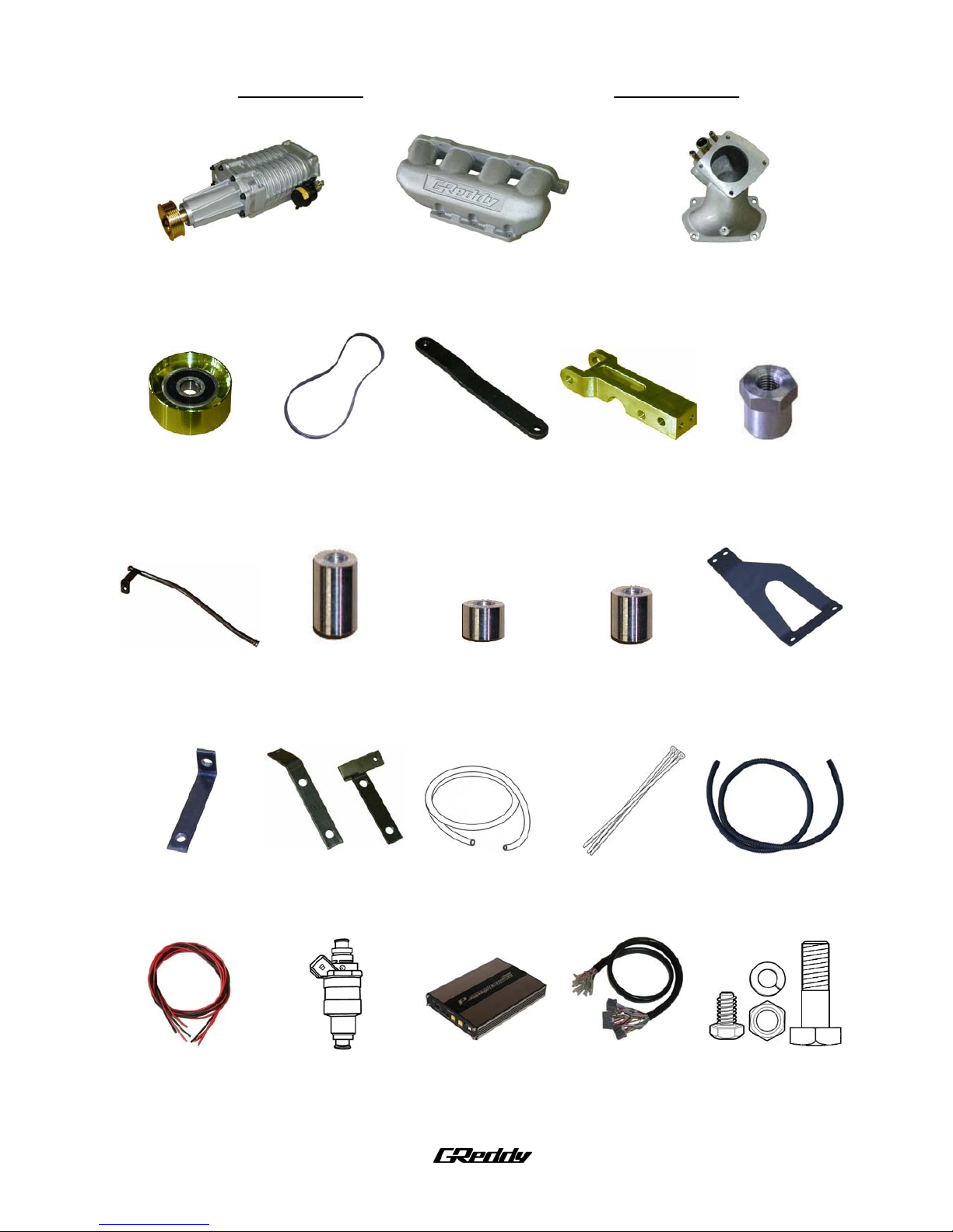
Part List Diagrams/Pictures
1 2 3
4 5 6 7 8
9 10 11 12 13
14 15 16 17,18 19
20 21 22 23 24~32
―4―
Page 5

2.OEM Parts Removal
Please refer to factory repair manual for OE component removal guidance.
2-1 Safely remove pressure from fuel lines.
(1) Remove the circuit-opening relay located in the fuse box in the left side of the engine bay.
[ C/O : circuit opening relay]
(2) Crank the motor to remove fuel pressure. Turn ignition key off.
(3) Remove the battery – and + terminal.
(4) Install the circuit-opening relay to its original location.
(5) Open fuel tank filler cap to remove pressure in fuel tank.
2-2 Remove the upper front fender apron seal (53735G), upper radiator support seal (53292A), and cylinder
head cover No. 2 (11212).
2-3 Remove the battery and battery tray.
2-4 Remove the engine under cover and drain the coolant from the radiator drain cock.
2-5 Remove the Engine bay ECM outlet duct
〔82776〕, air cleaner case 〔17700〕、and air cleaner hose
No. 1
〔17881A〕.
2-7 Remove the accelerator control cable from the throttle lever. Remove the water bypass hose,
ventilation hose No. 2
〔12262〕、and harness connectors from the throttle body. Remove throttle
body Assy.
※ Mark or label water bypass hose to prevent confusion during install.
Cars with Auto Cruise Control
(1) Remove the accelerator control cable from the throttle lever. Remove harness connector and
bolts. Remove the auto cruise control unit Assy.
(2) Remove the bracket from the control unit. Remove the four rubber grommets from bracket.
2-8 Remove the alternator bracket, oil dip stick guide, and oil dip stick.
※ Plug the dipstick guide hole on the engine block to prevent dirt from entering motor.
2-9 Remove the radiator reserve tank bolts and place the reserve tank on the hood latch. Disconnect
the ventilation hose No. 1 (12261) and remove the intake air surge tank.
2-10 Move the V belt tensioner to the front of the vehicle and remove the V belt.
2-11 Disconnect the harness connectors for the cam position sensor, A/C compressor, knock sensor,
crank position sensor, and injectors to allow the harness to move freely.
2-12 Disconnect the B+ connector and harness connector on the alternator and remove alternator.
2-13 Remove ventilation tube No. 1
〔12221〕.
―5―
Page 6
3.Kit Install
3-1 OE ventilation Tube No. 1 Modification
Remove the bracket from the ventilation tube in
2-13. Install back to same location.
※ After removing bracket, make sure to de-burr and
paint surface of modified area.
Please use safety glasses and a
mask to prevent injury.
Remove
Kit Alternator Bracket
3-2 Kit Lower Alternator Bracket Install
(1) Remove the two lower bolts of the A/C compressor
brackets. Place the provided spacers between the
kit alternator bracket and OE compressor bracket.
※ Replace the two bolts with the provided bolts. Do not
torque these bolts at this time.
〈Parts №11,13,30〉
Floating Nut
(2) Place the floating nut in the lower alternator bracket.
〈Parts №7,8〉
(3) Install the lower alternator bracket to the engine
block using the provided bolt and attach the
alternator bracket (1) to the lower alternator bracket.
※ Torque bolts in this order:
A/C compressor bracket, lower alternator bracket
(engine block side), alternator bracket.
Kit alternator
bracket
〈Parts №25,31〉
―6―
Page 7
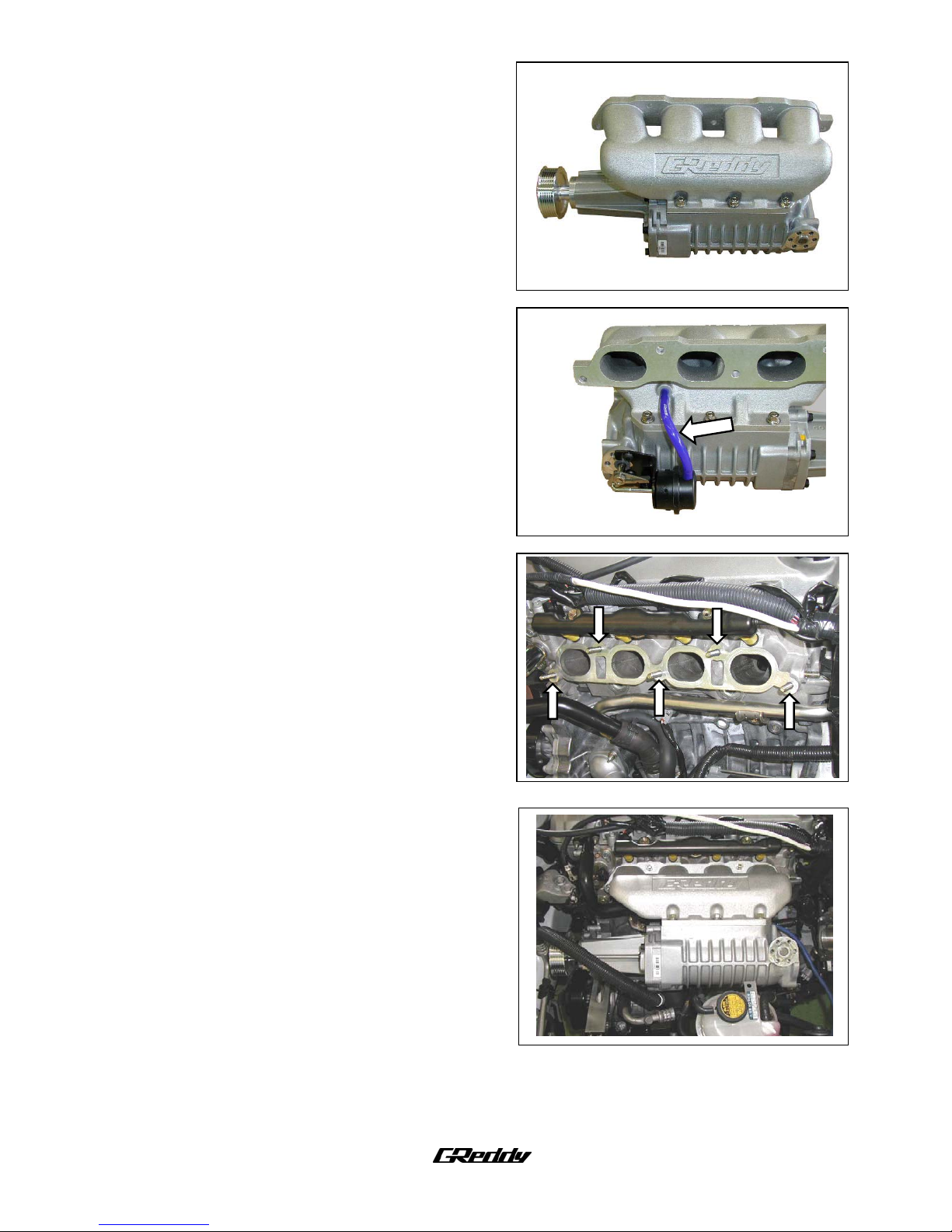
3-3 Kit Supercharger assembly
(1) Screw in the provided stud bolts onto the
supercharger outlet flange and apply silicone sealant
to the flange surface. Attach Kit intake manifold to
the supercharger.
※ Try to prevent sealant from protruding to the inside
of the manifold.
〈Parts №1,2,27〉
(2) Connect the actuator port to the intake manifold port
using the 6mm hose provided. Secure hose ends
with cable ties.
※ ※ When using a boost gauge, use this pressure source
to monitor intake manifold pressure.
〈Part №16,17〉
3-4 S/C Assy Installation
(1) Remove the OEM stud bolts on the intake side of the
cylinder head and screw in five of the studs provided.
〈Part №28〉
(2) Place the OEM intake manifold gasket between the
intake manifold and head and install manifold
When installing the intake manifold, place the radiator
reserve tank on the hood latch.
〈Part №28〉
―7―
Page 8
Kit dipstick
guide
OE dipstick
guide
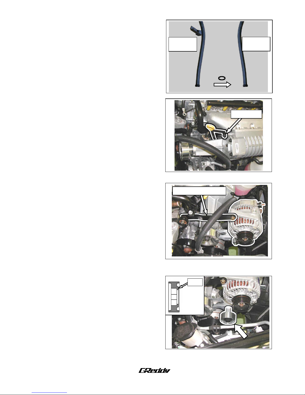
3-5 Kit Oil Dip Stick Installation
(1) Remove the O-ring from the OE dipstick guide and
place it on the Kit dipstick guide.
※
※
※
※
If the O-ring is damaged, please replace with OEM
part.
〈Part №9〉
(2) Place the Kit dipstick guide in the factory location on
the engine block and attach the bracket to the
supercharger Assy and tighten bolt.
Bracket bolt
3-6 Alternator Installation
(1) Attach the alternator to the lower alternator bracket
installed in step 3-2.
※ Use OEM bolt
(2) Attach the upper alternator bracket to the alternator
and torque the lower alternator bolt.
Use OE bolt on the alternator side of the bracket and
provided bolt for the engine side of bracket.
Upper alternator bracket
Torque spec: M8 bolt 29N・m (290kgf・cm)
M10 bolt 58N・m (580kgf・cm)
〈Parts №6,26〉
3-7 Kit Tensioner Pulley Installation
Rim
Attach the Kit tensioner pulley to the lower
alternator bracket with the spacer between the
pulley and bracket. Use the provided bolt to attach
pulley to bracket.
Place the pulley so the rim faces the bracket.
Use thread lock on the pulley bolt.
〈Parts №4,10,32〉
―8―
Page 9

3-8 Kit V Ribbed Belt Installation.
Adjust the tensioner pulley toward the front of the
vehicle to adjust belt tension.
〈Part №5〉
VP : Vane Pump Pulley
CK : Crank Pulley
CC : Cooler Compressor
WP : Water Pump Pulley
AL : Alternator Pulley
TP : OE Tensioner Pulley
kit TP : KIT Tenstioner Pulley
SC : Supercharger Pulley
3-9 Kit Injector Installation
(1) Remove the fuel delivery pipe and fuel injectors
(2) Replace OE injectors with the provided injectors and
install fuel delivery pipe back to original location.
Please check for fuels leaks after kit is
installed to prevent injury or damage from
fire.
※
※
※
Use the Kit O-ring to seal the top of the injector.
Lubricate O-ring with silicone grease.
Kit
O-ring
OE Insulator
Re-use OE bolts, spacer, and injectors insulators.
If the OE Insulator is damaged, please replace.
Injector connector direction
Install the injector connectors to face toward the
front of the vehicle.
〈Part №21〉
―9―
Page 10

(3) Cut off the OE injector harness connectors and
replace with Kit injector harness connectors.
※
※
※
※
※
Mark or label harness wires to ensure that they are
connected to the proper pin on the injector.
Do not connect the injector connector at this time.
Double check connections
④ Wrap with electrical tape
③ Solder wires
② Wrap wires together
① Remove sleeve
Solder procedure
3-10 OE Engine Wire Harness
C
D,E
B
A
(1) Split the OE Wire harness in this way: A – alternator
B+ wire, B – alternator connector, C – A/C
compressor, D – knock sensor, E – crank position
sensor. Wrap the wires with the provided colgate
tubing.
Combine the knock sensor and crank position sensor
wire harness into the same colgate tube.
Cut the colgate tube to the proper lengths and tape
then ends of the tubing with electrical tape.
〈Part №19〉
B,C,D,E
A
(2) Connect the sensor harness connectors and
alternator connectors and use cable ties to secure
wires. Connect engine harness to injector
connectors.
Route the alternator B+ wire in front of the
supercharger and connect to alternator.
〈Parts №17,18〉
―10―
Page 11

3-11 Kit Intake Tube Installation
(1) Remove the studs on the OE intake air surge tank
and screw them into the Kit intake tube.
〈Part №3〉
(2) Attach the Kit intake tube to the supercharger inlet.
At the same time, place the spacer between the Kit
intake tube bracket and “Thread A” on the picture
and use the M8 x 50mm bolt to secure the bracket.
Secure the other end of the bracket to the engine
block.
※
※
※
Use silicone sealant between the supercharger inlet
and intake tube flange. Prevent sealant from
protruding to the inside of the flange.
Torque bracket bolts starting from the engine.
Thread A
Spacer
Bracket spot
on engine
〈Parts №12,14,26,29,31〉
3-12 OE Throttle Body Installation
(1) Place the OE gasket on the intake tube and install
the throttle body, water bypass hose, and electrical
connectors.
Re-use OE bolts and nuts. Please confirm that the
throttle body gasket is place properly also.
(2) Install the accelerator control cable.
For vehicles without Auto Cruise Control
Install the accelerator control cable bracket to the
intake tube using the OE bolts and install the
throttle cable to the throttle lever.
―11―
Page 12

Bracket A
Bracket B
For Vehicles With Auto Cruise Control
① Place the rubber grommets removed in step 2-7
between the cruise control unit and the provided
auto cruise control brackets. Use OE screws to
secure bracket to unit.
〈Part №15〉
B
A
② Use the provided bolts to secure the auto cruise
control unit Assy to the upper radiator support.
Bolt Location
A : Hood latch bracket
B : Air cleaner box
〈Part №24〉
③ Cut the auto cruise control harness and use the
provided wire to extend the wire.
Cruise Control
Connector
After soldering wire and wrapping with tape,
wrap with colgate tube and connect harness to
unit.
※
※
※
Double check solder for good connection.
Make sure you have clearance between the
harness and V ribbed belt.
〈Parts №17,18,19,20〉
(3) Connect hoses back to the intake tube and throttle
body.
Re-use OE hose bands.
―12―
Page 13

Harness Grommet
Ground
A B
3-13 Kit e-manage Ultimate installation
(1) Remove the ECM box cover and disconnect and
remove connector A, B, and ground from the box.
Remove the electrical tape to all the harness
grommet to move freely. The ECM is on the right side
of the engine bay.
(2) Locate the A/C line going through the right side of
the firewall. Cut the grommet in the center to allow
the wire harness to pass through the firewall.
(3) Route the wire harness through the firewall.
〈Part №23〉
e-manage harness
(4) Route the e-manage harness through the ECM
harness grommet from the smaller end of the
grommet.
(5) Refer to the wire diagram to connect e-manage wires
to the ECM wire harness.
Wrap with heat shrink tube and electrical tape
Wrap wires and
solder together
Remove cover
After connections are completed, place all of the
wire connectors back in the ECM box and place the
harness grommet back to its original location.
※ Place the connectors A and B in the ECM box before
connectors C and D.
The kit does include connectors for electrical wiring, but it is highly recommended to solder
all wire connections to ensure proper function. Also please confirm that all wires are
wrapped with electrical tape.
―13―
Page 14

e-manage Ultimate Connector Harness Pin Location
C B
A
※ Viewing from wire harness side.
Ultimate
Pin №
Signal (Color)
OE ECM
Pin №
Signal
3 Ignition Input CH4(PL/W) A_11 Ignition Pulse IGT2 To ECM
4 Ignition Input CH2(O/W) A_12 Ignition Pulse IGT3 To ECM
5 Ignition Input CH1(BL/W) A_10 Ignition Pulse IGT1 To ECM
8 Ignition Output CH4(PL/B) A_11 Ignition Pulse IGT2 To Harness
9 Ignition Output CH3(Y/B) A_13 Ignition Pulse IGT4 To Harness
10 Ignition Input CH3(Y/W) A_13 Ignition Pulse IGT4 To ECM
11 Ignition Output CH2(O/B) A_12 Ignition Pulse IGT3 To Harness
12 Ignition Output CH1(BL/B) A_10 Ignition Pulse IGT1 To Harness
14 VTEC Output(Y) ― ―
15 Airflow (Voltage) Input (W) B_11 VG Air Flow Meter To Harness
16 Throttle Input(GY) B_23 VTA Throttle Signal
17 Injector Input CH1(BL/R) A_1 #10 Injector Pulse To ECM
18 Injector Input CH2(O/R) A_2 #20 Injector Pulse To ECM
19 Injector Input CH3(Y/R) A_3 #30 Injector Pulse To ECM
20 Injector Input CH4(PL/R) A_4 #40 Injector Pulse To ECM
22 Airflow (Voltage) Output(G) B_11 VG Air Flow Meter To ECM
23 RPM Signal (BR) C_27 TACH RPM Signal
24 Ground (B) B_17 E1 Ground
25 IG Power (R) D_16 +B Battery Power
30 Injector Ground (B/R) A_21 E01 Injector Ground
33 Crank Angle Signal (GY/W) ― ―
34 Injector Output CH1(BL/GY) A_1 #10 Injector Pulse To Harness
35 Injector Output CH2(O/GY) A_2 #20 Injector Pulse To Harness
36 Injector Output CH3(Y/GY) A_3 #30 Injector Pulse To Harness
39 Camshaft Angle Signal (GY/B) ― ―
40 Vehicle Speed Output (BR/Y) ― ―
41 Vehicle Speed Input (LB/Y) ― ―
42 Injector Output CH4(PL/GY) A_4 #40 Injector Pulse To Harness
―14―
Page 15

These wire are outlined in the e-manage diagram. These wires will not be used in this kit. Use
electrical tape to cover the ends of the wires to prevent short circuit.
№14 VTEC Output(Y)
№33 Crank Angle Signal(GY/W)
№39 Camshaft Angle Signal(GY/B)
№40 Vehicle Speed Output(BR/Y)
№41 Vehicle Speed Input (LB/Y)
OE ECM Wire Pin Diagram ※Viewing from wire harness side
CONNECTOR D(22P) CONNECTOR C(28P) CONNECTOR B(24P) CONNECTOR A(31P)
e-manage Ultimate Wire Diagram
Male Female
Splice
Connector
22(G
)
1
15(W)
34(B/GY)
36(Y/GY)
19(Y/R)
17(B/R)
35(O/GY)
18(O/R)
42(PL/GY)
20(PL/R)
30(B/R)
10(Y/W)
9(Y/W)
4(O/W)
11(O/B)
3(PL/W)
8(PL/B)
5(BL/W)
12(BL/B)
16(GY) 24(B)
23(BR)
25(R)
Color Code: W-White, G-Green, B-Black, BL-Blue, BR-Brown, R-Red, GY-Grey, PL-Purple
Y-Yellow, O-Orange, LB-Light, PI-Pink
―15―
Page 16

(6) Route the e-manage ultimate wire harness safely though the engine bay and use cable ties to secure the
harness and prevent it from moving. Place the A/C line grommet in its original location.
※
※
※
※
Use cable ties to secure the harness to the accelerator control cable secure areas. 〈Part №18〉
(7) Adjust the dipswitches on the e-manage Ultimate unit. Secure the unit and plug in the harness
connectors.
Refer to the diagram below for dipswitch instructions.
It is important that you adjust these switches properly.
Engine damage may be caused if not set properly
Secure the e-manage unit in an area free from moisture, dust, sunlight, and direct heat from
the heater vents.
Please try to avoid placing the e-manage unit under the carpet or floor mats.
○ Front Panel Dip Switch Settings
Application Switch Setting
・Use with OE Air Cleaner Box
※1,3-ON
・Use with AIRINX Filter Kit
・Factory setting
※1,2,3,4-ON
3-14 OE Air Cleaner Installation
Install the air cleaner case, air cleaner hose No.1, engine bay ECM outlet duct, and upper radiator
support seal.
※ If installing AIRINX Air Filter Set, refer to AIRINX instruction manual.
3-15 OE Cylinder Head Cover Modification
Cut the highlighted portion of the cylinder head
cover No.2 in the picture on the right.
Re-use the OE bolts.
Please use safety glasses and a
mask to prevent injury.
―16―
Page 17

3-16 Starting the Engine
(1) Install the radiator reserve tank to its original location and fill with coolant.
Bleed the air from the cooling system after starting engine.
(2) Install the battery tray and batter. Connect the B+ terminal of the battery.
(3) Inspect all harness connectors and wire connections and connect the B – terminal of the batter.
(4) Start the engine and inspect fuel lines and injectors for any fuel leaks.
※ ※ Check the e-manage unit to see if the active light is green. If it is not, please check the e-manage
wire connections to the OE ECM.
Check to see if the e-manage unit has error codes (active light blinks red).
(5) At idling, inspect for water or vacuum leaks.
(6) Install the RH engine under cover.
(7) Install the upper front fender apron seal and cylinder head cover No.2.
This completes the Supercharger Kit installation
IMPORTANT
o It is very important that you monitor the boost pressure, and make sure not to over boost.
Over boosting can cause engine damage.
o GReddy Performance Products, Inc. is not responsible for any engine damage caused by over
boosting (increased boost), modification to the kit, and/or misuse of the product. NO
WARRANTY is offered.
o Due to lack of control over proper installation and use of this product,
NO WARRANTY is offered for this kit.
―17―
Page 18

Front Fender Apron & Dash Panel
Page 19

Cylinder Head
Page 20

Suspension Cross Member and Under Cover
Page 21

Switch and Relay
Page 22

Air Cleaner
Page 23

Fuel Injection System
Page 24

Ventilation Hose
Page 25

Cylinder Block
Page 26

Manifold
 Loading...