

Page 1
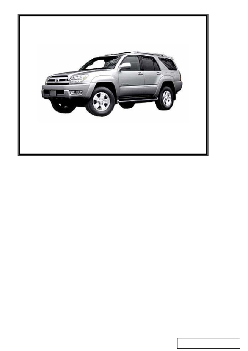
TOYOTA
4RUNNER
DVD Rear Seat
Entertainment System
Diagnostic Manual
MDC # 00107-00358
Page 2
DVD Diagnostics - 1
Page 1 of 38 pages Supplier Ref #: DIO
Issue: A 01/12/04
SYSTEM DESCRIPTION
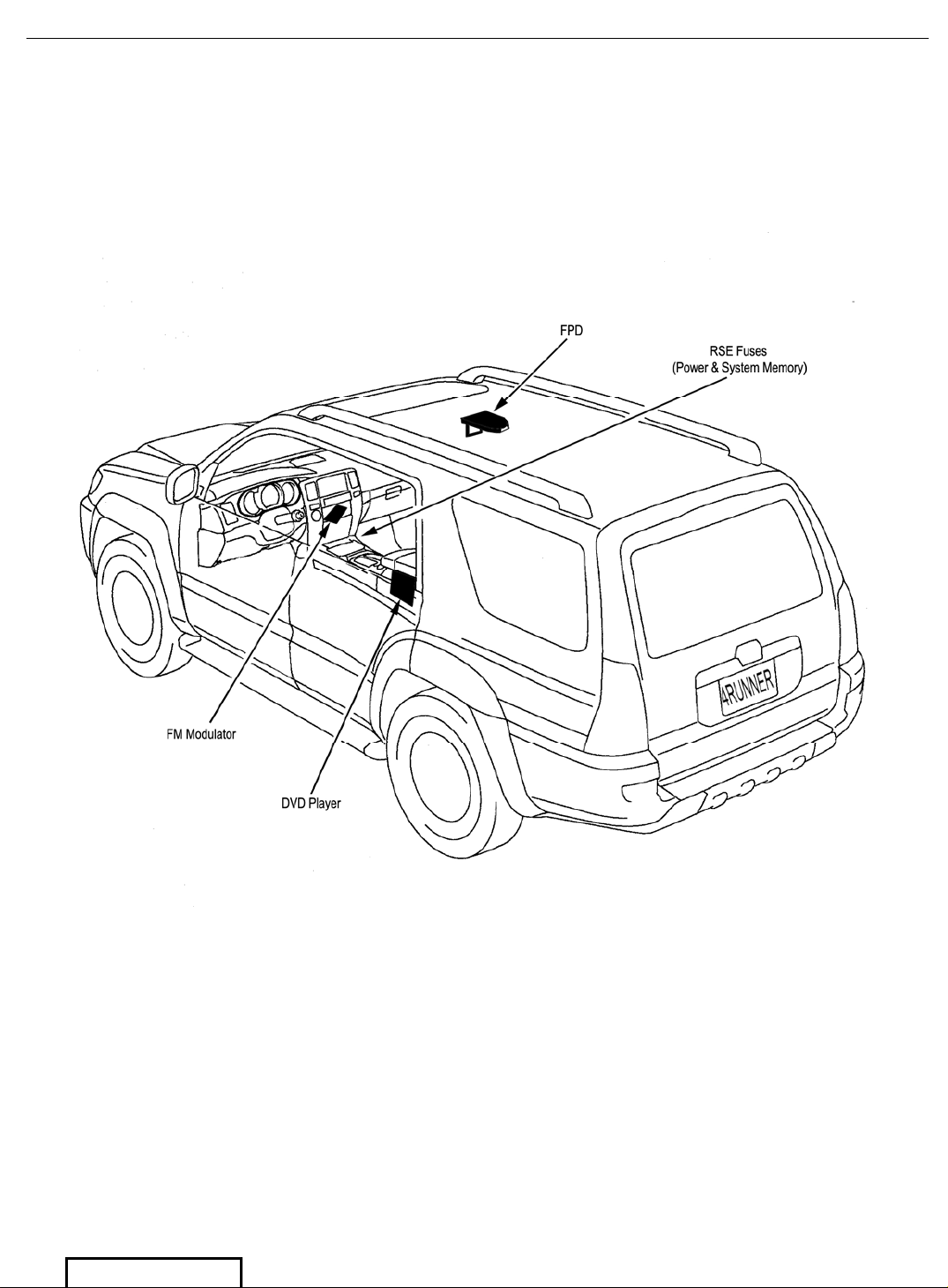
The Rear Seat Entertainment (RSE) System consists of five basic components: (See Figure 1.
RSE Main Component Layout)
1. The Flat Panel Display (FPD) Screen
2. The DVD player, located in the Center Console
3. FM Modulator, located beneath the Vehicle Radio
4. Remote Control
5. Wireless IR (Infra-red) Headphones
The RSE System can display video from two sources: DVD Video Disc and AUX inputs. Audio can
be heard on the Vehicle Speakers, Wireless Headphones and Wired Headphones. AUX Video and
Audio Input jacks are located on the front of the DVD Player Console.
For disassembly instructions, refer to RSE Installation Instructions: PT900-8903D-03/16
PT900-8903S-03/16
Pre-Check
1. Confirm that the Vehicle Battery voltage is 10.5 volts minimum. If the Battery is below 10.5
volts, the system is designed to shut down to avoid discharging the Battery.
2. Turn the ignition switch to the ACC/ON position, turn system ON by opening the FPD
Screen and by pressing the Power button on the DVD Player or on the Remote Control.
Check that the TOYOTA Logo appears on the FPD Screen.
RSE Status Indicator Light
The Status Indicator Light, located between the power and play/pause buttons on the DVD Player,
alerts the user to various functions or problems of the RSE. The Status Indicator Light will be
Green when the RSE is on standby or is playing. In case of an error, the Status Indicator Light will
blink until the error is corrected, up to a maximum-programmed time. The various states of the
Status Indicator Light are as follows:
Status Indicator Light OFF: The Green Light is OFF when the system is turned OFF.
Green Status Indicator Light: A steady Green Light indicates normal operation.
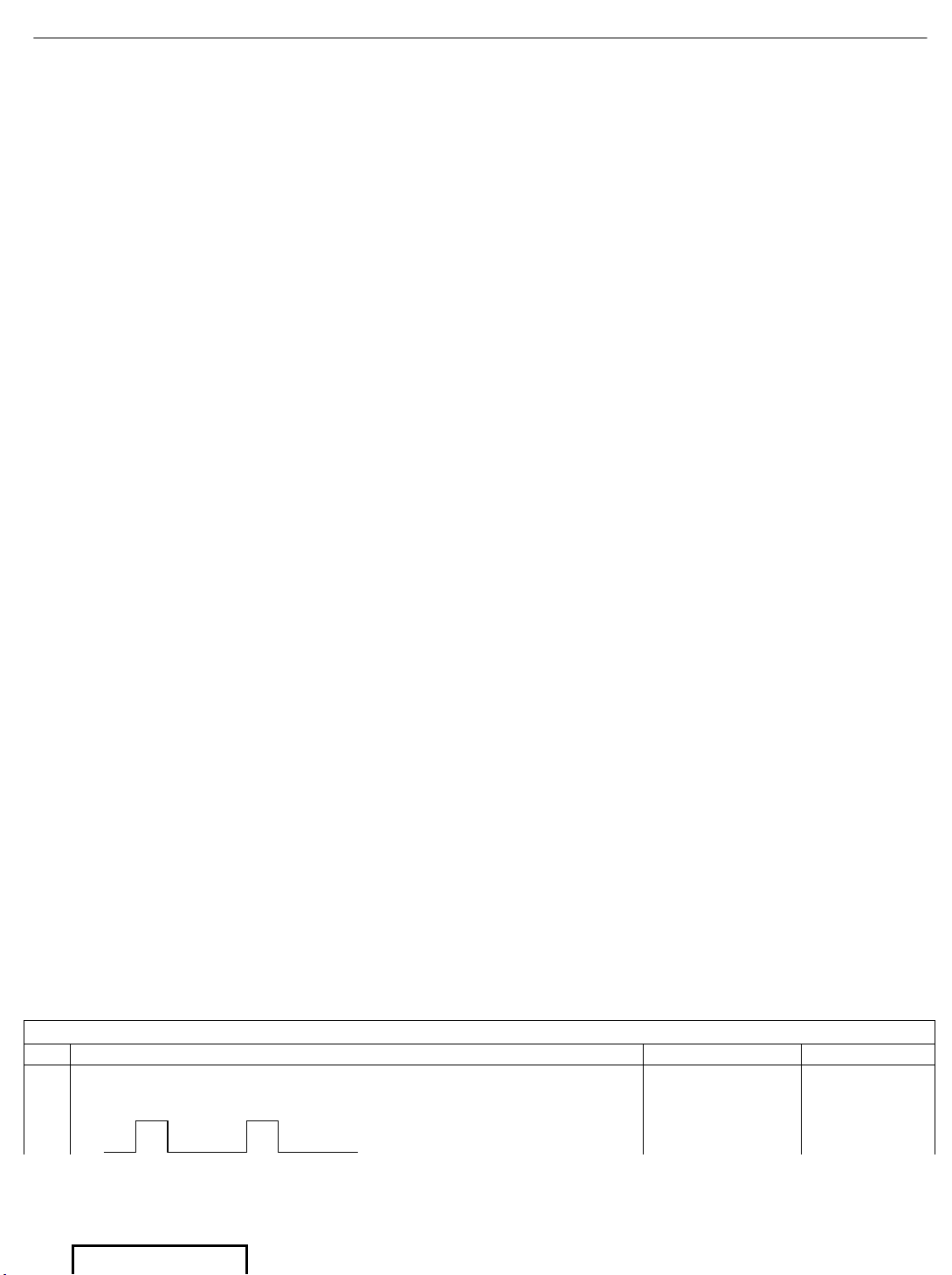
Status Indicator Light Blinking: The RSE system is programmed with six different Status
Indicator Light blink sequences, which can be used to troubleshoot the RSE system. The blink
sequences and indications are as follows:
1. One Blink - Power Failure (ACC abnormal power OFF) (Go to Step A1)
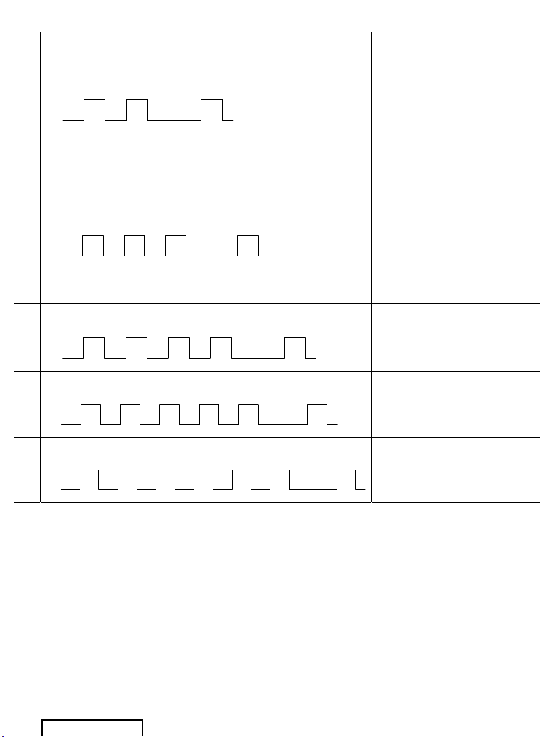
2. Two Blinks - Voltage Over Limit. (Out of range from 9 to 16 volts) (Go to Step A2)
3. Three Blinks - Temperature Over Limit. (Go to Step A3)
4. Four Blinks - Communication Error between CIM and FPD (Go to Step A4)
5. Five Blinks - Rotational Angle of the FPD is less than 20 degrees (Go to Step A5)
6. Six Blinks - Communication Error between CIM and DVD (Go to Step A6)
Blinking Status Indicator Light Quick Troubleshooting Guide
Blink Sequence Indication Solution
A1
The Status Indicator Light is blinking in a steady sequence
ON/OFF - ON/OFF
1
Blink
300 mSec
On
300 mSec
On
1 Second
Off
There is a power
failure related to
an ACC abnormal
power off
Proceed with
Symptom B1
Page 3
DVD Diagnostics - 2
Page 2 of 38 pages Supplier Ref #: DIO
Issue: A 01/12/04
A2
The Status Indicator Light is blinking in a steady sequence
ON/ON/OFF - ON/ON/OFF
2
Blinks
300 mSec
On
300 mSec
On
300 mSec
On
300 mSec
Off
1 Second
Off
The minimum or
maximum voltage
operating range of
the RSE has been
exceeded. Prior to
the blinking
sequence, the
FPD screen will
display “VOLT
LIMIT Shutdown
in 5 Sec.”.
Verify Battery
Voltage to be
between 10.5
and 15.8 VDC.
A3
The Status Indicator Light is blinking in a steady sequence
ON/ON/ON/OFF - ON/ON/ON/OFF
3
Blinks
300 mSec
On
300 mSec
On
300 mSec
On
300 mSec
On
300 mSec
Off
300 mSec
Off
1 Second
Off
The minimum or
maximum
operating
temperature range
of the RSE has
been exceeded.
Prior to the
blinking
sequence, the
FPD screen will
display “TEMP
LIMIT Shutdown
in 5 Sec.”.
Shutdown the
RSE system
and allow time
for the system
to either cool
down or allow
time for the
system to
warm up.
A4
The Status Indicator Light is blinking in a steady sequence
ON/ON/ON/ON/OFF- ON/ON/ON/ON/OFF
4
Blinks
300 mSec
On
300 mSec
On
300 mSec
On
300 mSec
On
300 mSec
On
300 mSec
Off
300 mSec
Off
300 mSec
Off
1 Second
Off
There is a
communication
error between the
CIM and FPD
Proceed with
Symptom B1
A5
The Status Indicator Light is blinking in a steady sequence
ON/ON/ON/ON/ON/OFF - ON/ON/ON/ON/ON/OFF
5
Blinks
300 mSec
On
300 mSec
On
300 mSec
On
300 mSec
On
300 mSec
On
300 mSec
On
300 mSec
Off
300 mSec
Off
300 mSec
Off
300 mSec
Off
1 Second
Off
The rotational
angle of the FPD
is less than 20º
Open the FPD
Screen greater
than the 20º
minimum
viewing angle.
A6
The Status Indicator Light is blinking in a steady sequence
ON/ON/ON/ON/ON/ON/OFF - ON/ON/ON/ON/ON/ON/OFF
6
Blinks
300 mSec
On
300 mSec
On
300 mSec
On
300 mSec
On
300 mSec
On
300 mSec
On
300 mSec
On
300 mSec
Off
300 mSec
Off
300 mSec
Off
300 mSec
Off
300 mSec
Off
1 Second
Off
There is a
communication
error between the
CIM and DVD
Proceed with
Symptom B1
Page 4
DVD Diagnostics - 3
Page 3 of 38 pages Supplier Ref #: DIO
Issue: A 01/12/04
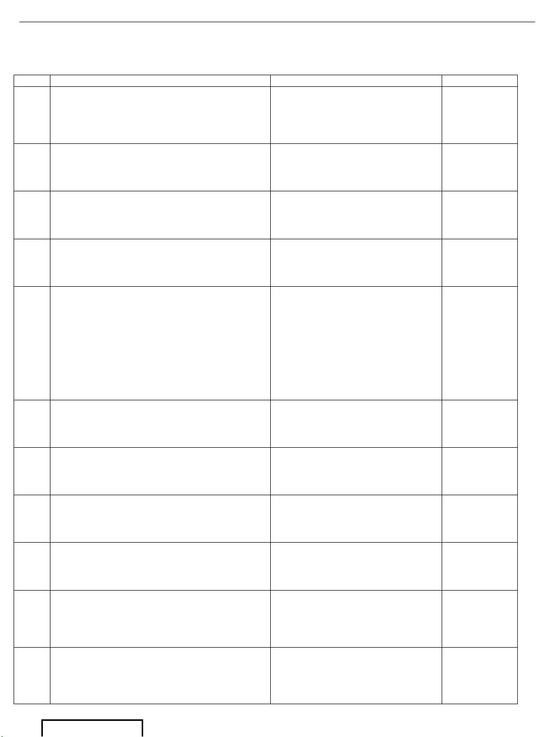
PROBLEM SYMPTOMS TABLE
Proceed with troubleshooting of each circuit in the table below.
Symptom Suspect Area See Page
B1 No TOYOTA Logo, No Video, Dark Screen
1. Low Battery Voltage
2. Fuse
3. Connector/Cable
4. FPD
5. DVD Player
5
B2
No Video Play but the TOYOTA Logo
appears on Screen
1. Remote Control
2. Remote Control Batteries
3. DVD Player
9
B3 Poor Video Quality
1. DVD Disc
2. DVD Player
3. FPD Assembly
10
B4
No Video in AUX mode when external source
is provided but DVD mode functions
properly
1. Remote Control
2. DVD Player
11
B5
No Audio on Vehicle Speakers, while the
Audio on Wireless IR and or Wired
Headphones is OK
1. FM Modulator (FMM) is OFF
2. Vehicle Radio is not tuned to
FMM frequency
3. Antenna Cable from FMM is
not plugged into Vehicle
Radio.
4. FM Modulator
5. Connector/Cable
6. Remote Control
7. DVD Player
12
B6 No Audio on Wireless IR Headphones
1. Wireless Headphones
Batteries
2. Wireless IR Headphones
3. FPD Assembly
15
B7
No Audio on Wired Headphones, while the
Audio on Wireless IR and or Vehicle
Speakers is OK
1. Wired Headphones
2. DVD Player
17
B8 Disc plays, but will not eject
1. DVD Player 18
B9
DVD Player will not accept disc. The
TOYOTA logo appears on the screen
1. DVD Player 19
B10
DVD System will not respond to any of the
remote control functions, but TOYOTA Logo
appears on FPD and/or DVD disc auto starts
and/or FPD shows Disc menu when the
IG/ACC is ON
1. Remote Control
2. Remote Control Batteries
3. FPD Assembly
20
B11 The Dome Light in the FPD does not work
1. Light Bulb
2. Dome light Cable/Connector
3. FPD Assembly
4. Main Harness/Fuse
5. Vehicle Battery
22
Page 5

DVD Diagnostics - 4
Page 4 of 38 pages Supplier Ref #: DIO
Issue: A 01/12/04
B12
DVD disc will not resume last position after
the vehicle has been turned OFF and then
turned ON again
1. Vehicle Radio Fuse #2 (25
Amp)
2. Vehicle Wire Harness
3. RSE Main Wire Harness
25
Page 6
DVD Diagnostics - 5
Page 5 of 38 pages Supplier Ref #: DIO
Issue: A 01/12/04
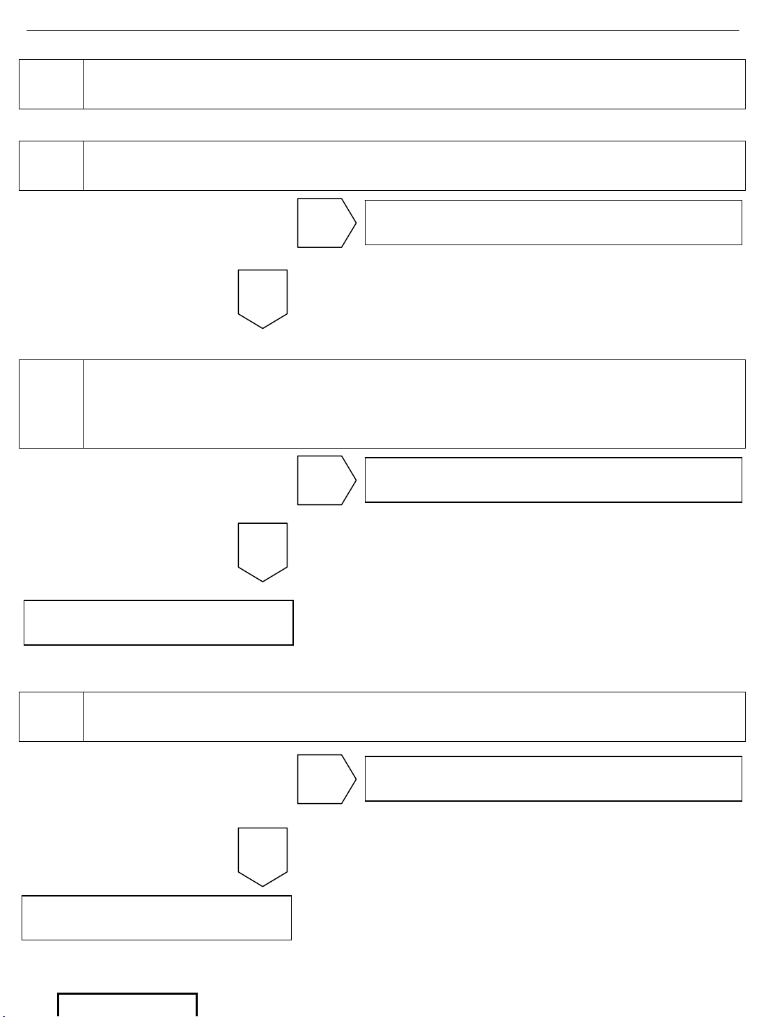
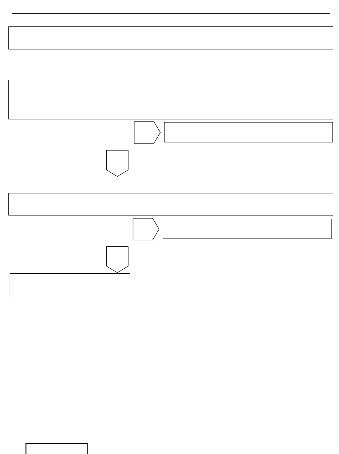
B1 SYMPTOM: No TOYOTA Logo, No Video, Dark Screen
1 Check the Vehicle Radio for Power and Sound.
2
Check that the DVD Player backlight turns on by pressing the power
button. The Power button should glow RED while the Play/Pause and
the Stop/Eject buttons glow bright GREEN. Ignition Switch must be in
the ACC/ON position with the FPD Screen down.
3 Check Vehicle Radio Fuse #1 (7.5 Amp) and Radio Fuse #2 (25 Amp)
Go to step 3
NG
OK
Go to step 4
NG
OK
Go to step 12
NG
OK
Go to step 10
Go to step 7
Page 7
DVD Diagnostics - 6
Page 6 of 38 pages Supplier Ref #: DIO
Issue: A 01/12/04
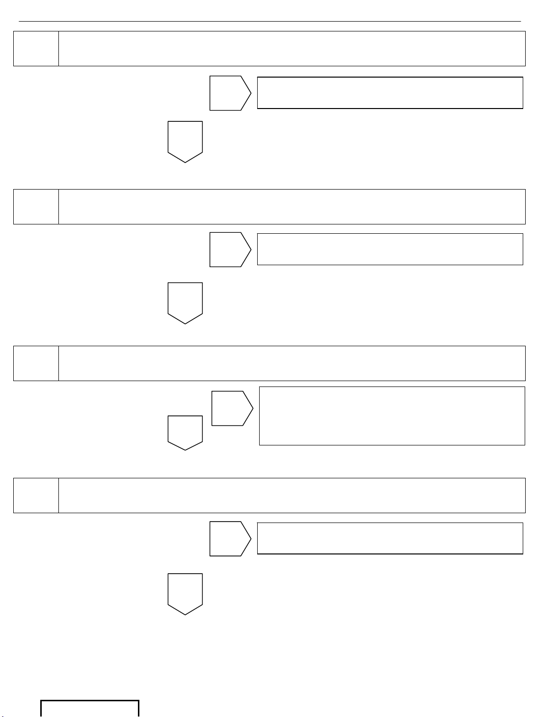
4 Check the two (5 Amp) Fuses on the B+ and ACC input power lines
5
Check the B+ and ACC voltages on Pins 1 and 3 and continuity to
ground on Pin 2 of connector P13
6
Check the B+ and ACC voltages on Pins 1 and 2 and continuity to
ground on Pin 3 on connector P21 of the DVD Player.
7
Disconnect P12 and check the +7.5 voltage on Pin 1 and continuity to
ground on Pin 2.
OK
Go to step Replace T-Harness
NG
OK
Go to step Replace DVD Player
NG
Go to step
The harness from the DVD Player to the
Input Power connector is defective
Re
p
lace RSE Main Wire Harness
NG
OK
Go to step Replace Fuse(s) and Retest
NG
Page 8
DVD Diagnostics - 7
Page 7 of 38 pages Supplier Ref #: DIO
Issue: A 01/12/04
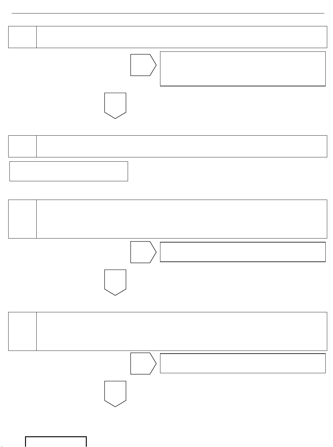
8
Reconnect P12 to the DVD Player and disconnect P103 of the FPD.
Check the +7.5 voltage on Pin 1 and continuity to ground on Pin 2.
9 Replace FPD.
10
For 8 Speaker System: Check B+ and ACC voltages on Pins 1 and 11
and continuity to ground on Pin 20 of connector J303
For 6 Speaker System: Check B+ and ACC voltages on Pins 4 and 3
and continuity to ground on Pin 7 of connector J305
11
For 8 Speaker System: Check B+ and ACC voltages on Pins 1 and 11
and continuity to ground on Pin 20 of connector P302
For 6 Speaker System: Check B+ and ACC voltages on Pins 4 and 3
and continuity to ground on Pin 7 of connector P304
End
Go to step
The harness from the DVD Player to the
FPD is defective.
Replace RSE Main Wire Harness.
NG
OK
Go to step Check Vehicle Main Harness
NG
OK
Go to step Replace T-Harness
NG
OK
Page 9
DVD Diagnostics - 8
Page 8 of 38 pages Supplier Ref #: DIO
Issue: A 01/12/04
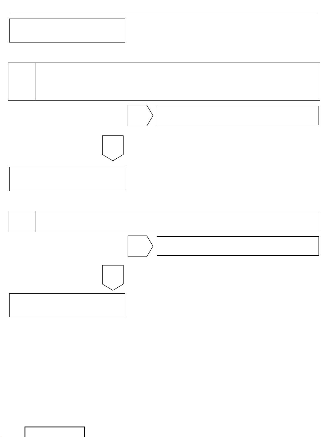
12
For 8 speaker systems, Disconnect P302, Replace Blown Fuse(s) and
Re-check Vehicle Radio Fuse #1 (7.5 Amp) and Radio Fuse #2 (25 Amp)
For 6 speaker systems, Disconnect P304, Replace Blown Fuse(s) and
Re-check Vehicle Radio Fuse #1 (7.5 Amp) and Radio Fuse #2 (25 Amp)
13 Replace T-Harness and Re-test
OK
OK
Go to step Vehicle Radio not working properly
NG
Go to step 1
Go to step Go to step 13
NG
Go to step 1
Go to step 1
Page 10
DVD Diagnostics - 9
Page 9 of 38 pages Supplier Ref #: DIO
Issue: A 01/12/04
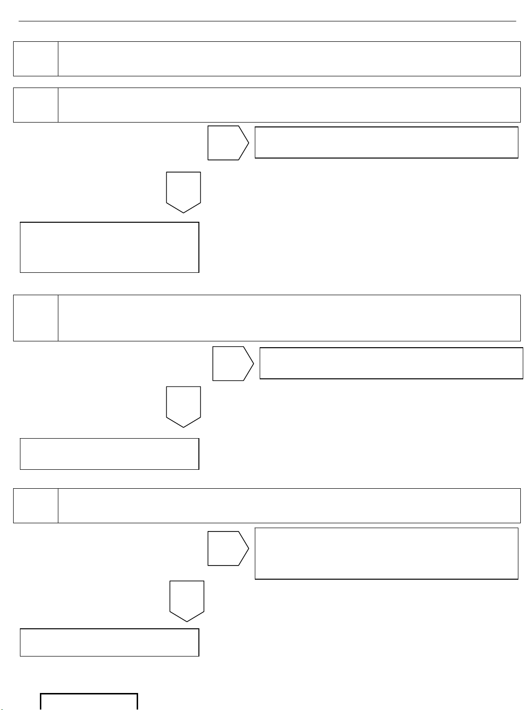
B2
SYMPTOM: No Video Play but the TOYOTA Logo appears on
Screen.
If the logo appears, this signifies that power is available at the FPD. This condition focuses our
attention on the DVD player.
1
Check the DVD System response to the Remote Control commands.
Pressing the Source button on the remote will activate either the DVD
or AUX mode and display the mode in the center of the screen for
approximately two seconds
2
Insert a DVD disc and verify it is accepted. The video will start playing
or the disc menu will appear on the screen
OK
Go to step Go to B10 Remote Control Problems
NG
OK
Go to step Replace DVD Player
NG
End.
System Functions Properly
Page 11
DVD Diagnostics - 10
Page 10 of 38 pages Supplier Ref #: DIO
Issue: A 01/12/04
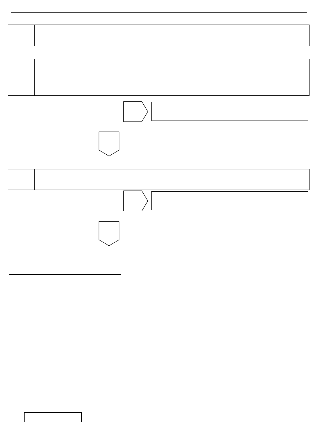
B3 SYMPTOM: Poor Video Quality.
1 Check video performance with various DVD discs.
2
Check external video performance. Press the Source button on the
remote control to activate AUX mode and connect an external video
source to the AUX input on the DVD console
3
Disconnect P12 and P103. Verify continuity between each pin of the
connectors.
OK
Go to step Go to step 2
NG
OK
Go to step Go to step 3
NG
Go to step Replace DVD Player
Go to step
End.
First DVD disc is defective.
System OK.
Go to step
Harness from the DVD Player to the
FPD is defective.
Replace RSE Main Wire Harness
NG
Go to step
Replace FPD Assembly
OK
Page 12
DVD Diagnostics - 11
Page 11 of 38 pages Supplier Ref #: DIO
Issue: A 01/12/04
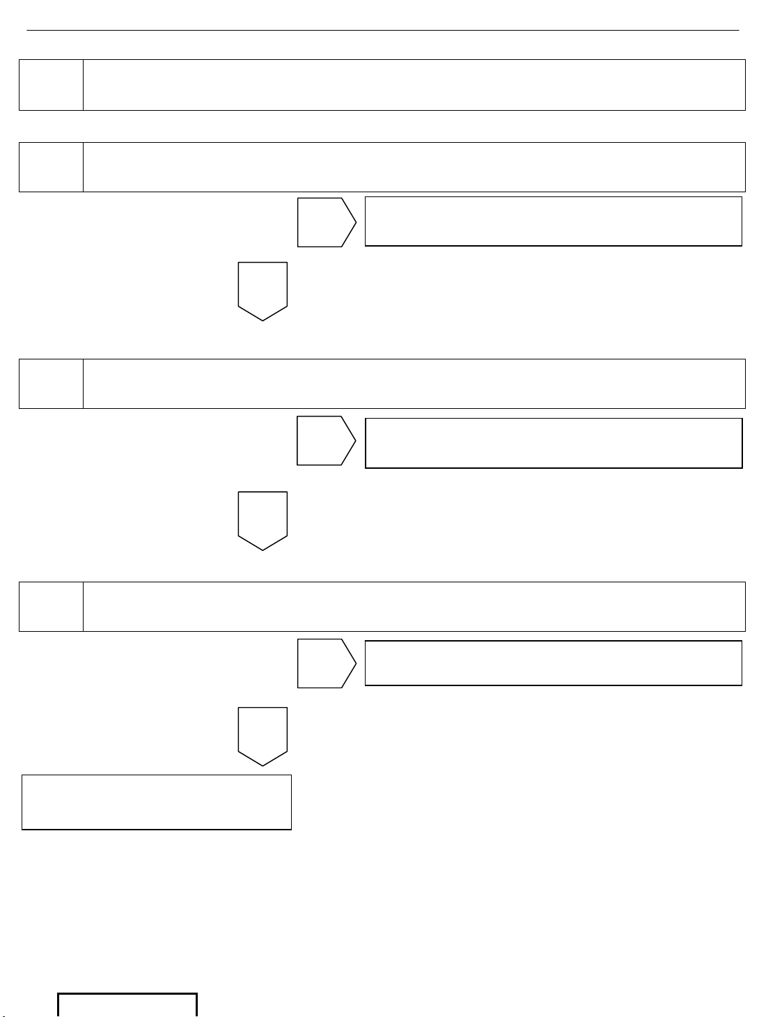
B4
SYMPTOM: No Video in AUX mode when external source is
connected, but DVD mode functions properly
1
Check the DVD system response to the remote control commands.
Pressing the Source button on the remote will activate either the DVD
or AUX mode and display the mode in the center of the screen for
approximately two seconds
2
Check the AUX with external source and confirm video appears on
screen
OK
Go to step Go to B10 Remote Control Problems
NG
OK
Go to step Replace the DVD Player
NG
End.
System Functions Properly
Page 13
DVD Diagnostics - 12
Page 12 of 38 pages Supplier Ref #: DIO
Issue: A 01/12/04
B5
SYMPTOM: No Audio on Vehicle Speakers, but Audio is
present on Wireless and/or Wired Headphones
1
Check that the FM Modulator is turned ON. Using the Remote Control,
press the FMM ON/OFF Button. The screen will display FMM ON or OFF
2
Check that the Vehicle Radio is turned ON and tuned to the same FM
Modulator Frequency
3 Check if Audio is present on Vehicle Speakers
OK
Go to step
Go to B10, Remote Control Problems
NG
OK
Tune the Vehicle Radio to the correct
FM Modulator fre
q
uency.
NG
OK
Go to step Go to step 4
NG
End.
System Functions Properly
Page 14
DVD Diagnostics - 13
Page 13 of 38 pages Supplier Ref #: DIO
Issue: A 01/12/04
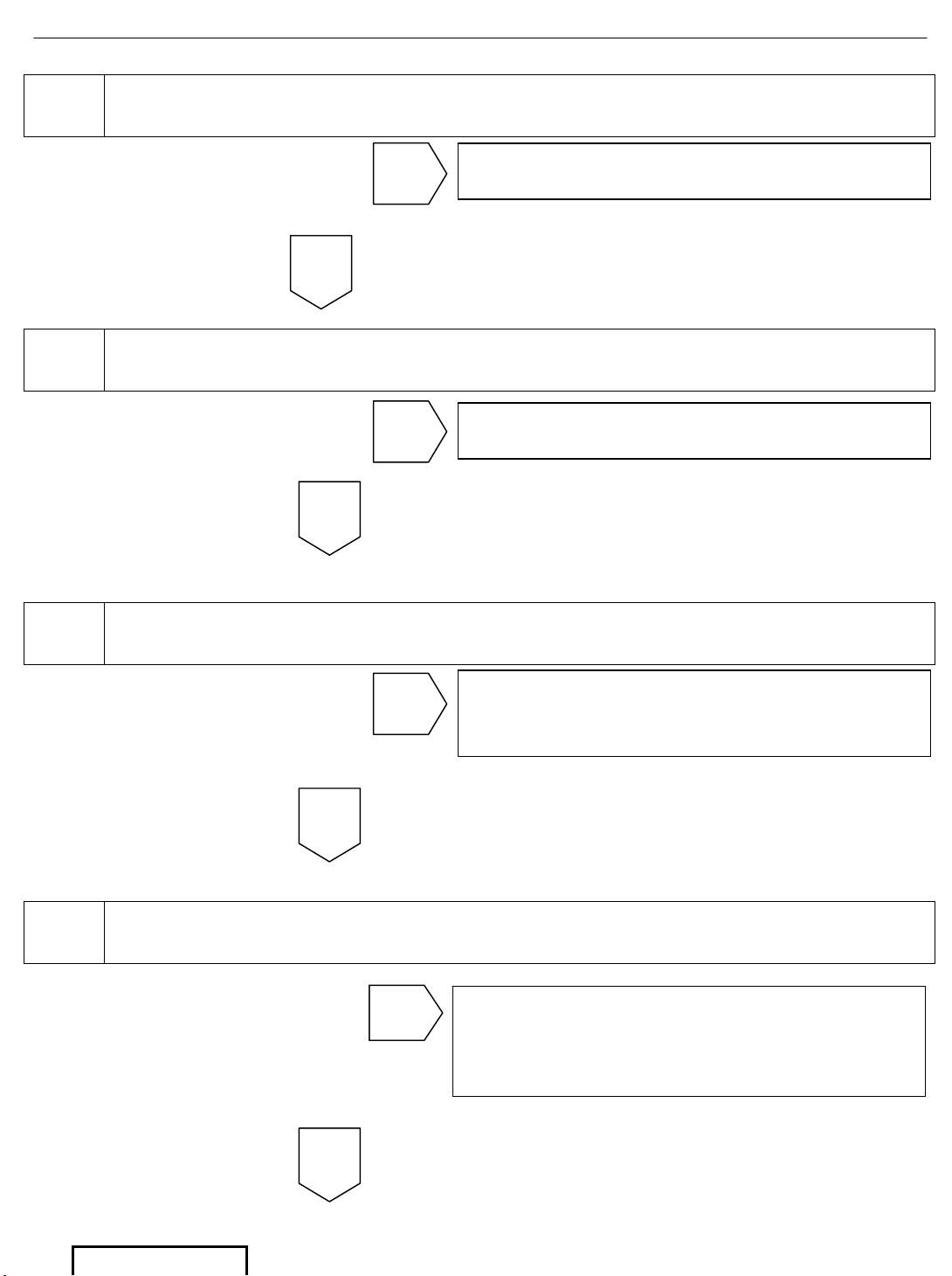
4
Check that the Connectors P20 and P307 are properly connected to the
DVD Player and FM Modulator.
5
Disconnect Connector P20 and check the voltage on Pin 1 (+7.5 Volts)
and continuity to ground on Pins 6 and 7
6
Re-connect Connector P20 and disconnect Connector P307. Check
voltage on Pin 1 (+7.5 Volts) and continuity to ground on Pins 6 and 7.
7
Verify that the Vehicle Antenna is connected into the FM Modulator and
that the FM Modulator is connected into the Vehicle Radio
OK
Go to step Replace DVD Player
NG
Go to step
The harness from the DVD Player to the
FM Modulator is defective. Replace the
NG
OK
OK
OK
NG
Go to step Re-connect and Re-Test at Step 3
Go to step
Connect Vehicle Antenna to the FM
Modulator and/or FM Modulator to the
Radio
Page 15
DVD Diagnostics - 14
Page 14 of 38 pages Supplier Ref #: DIO
Issue: A 01/12/04
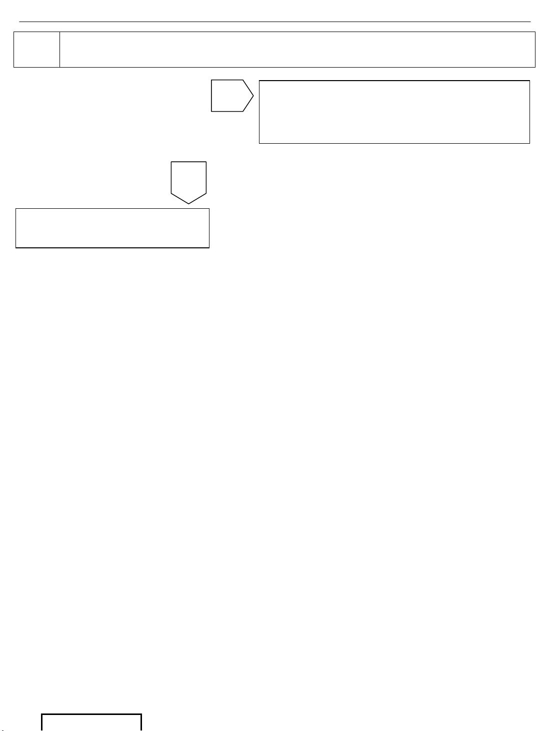
8
Disconnect P307 and P20. Verify continuity between each pin of the
connectors.
OK
Go to step
The harness from the DVD player to the
FM Modulator is defective.
Re
p
lace the RSE Main Wire Harness.
Replace FM Modulator
Page 16
DVD Diagnostics - 15
Page 15 of 38 pages Supplier Ref #: DIO
Issue: A 01/12/04
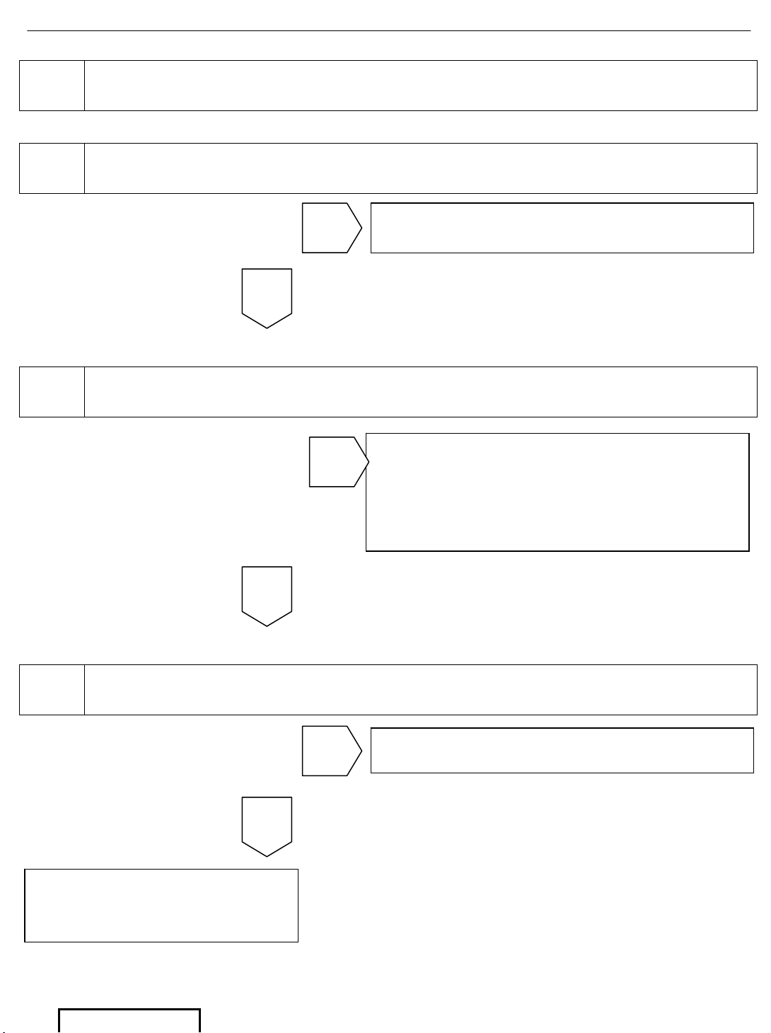
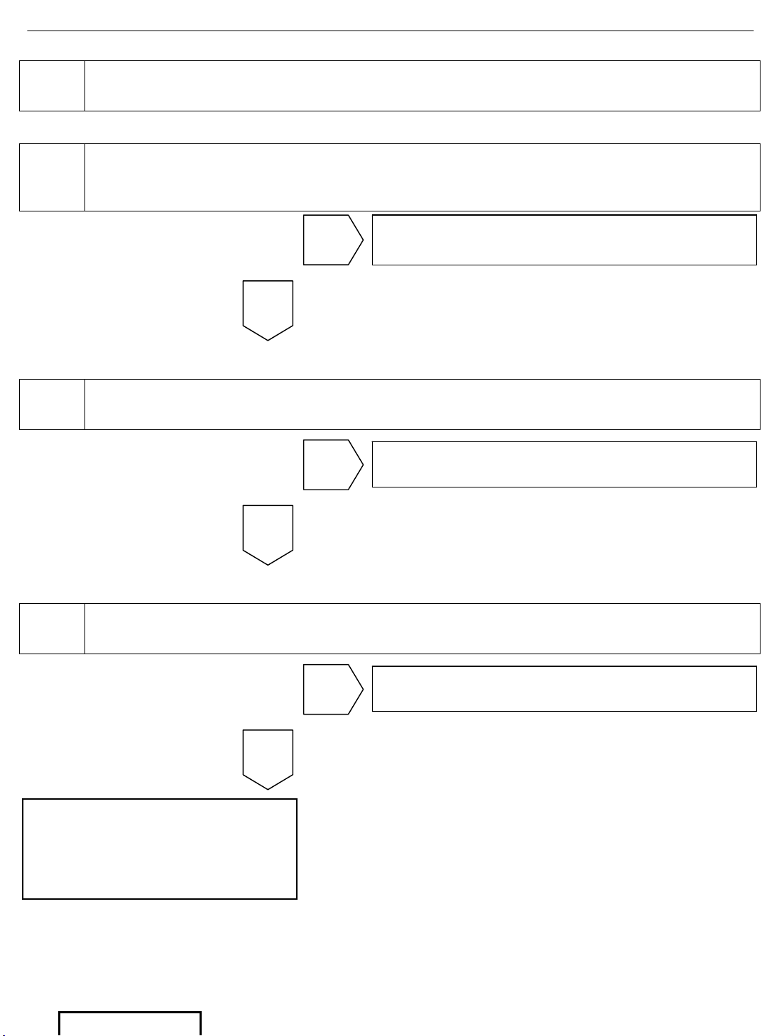
B6 SYMPTOM: No Audio on TOYOTA Wireless IR Headphones
1
Check that the Red LED Indicator, on the Wireless Headphones, turns
ON when the IR Headphones are turned ON
2
Check that the FPD IR Transmitter is turned ON in the System Menu.
Press System Menu button on the Remote Control
3 Check Audio with a second Wireless IR Headphone.
OK
Go to step
Replace batteries and go to step 1
NG
OK
Press the System Menu button on the
Remote Control.
Press the
T button 3 times then the X
button 1 time to change the IR
Transmitter from OFF to ON
NG
Go to step Go to step 4
NG
OK
System functions properly.
The first headphone was
not working properly.
Page 17
DVD Diagnostics - 16
Page 16 of 38 pages Supplier Ref #: DIO
Issue: A 01/12/04
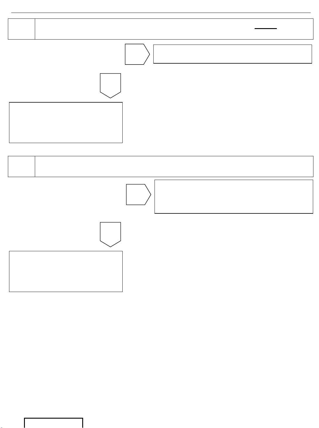
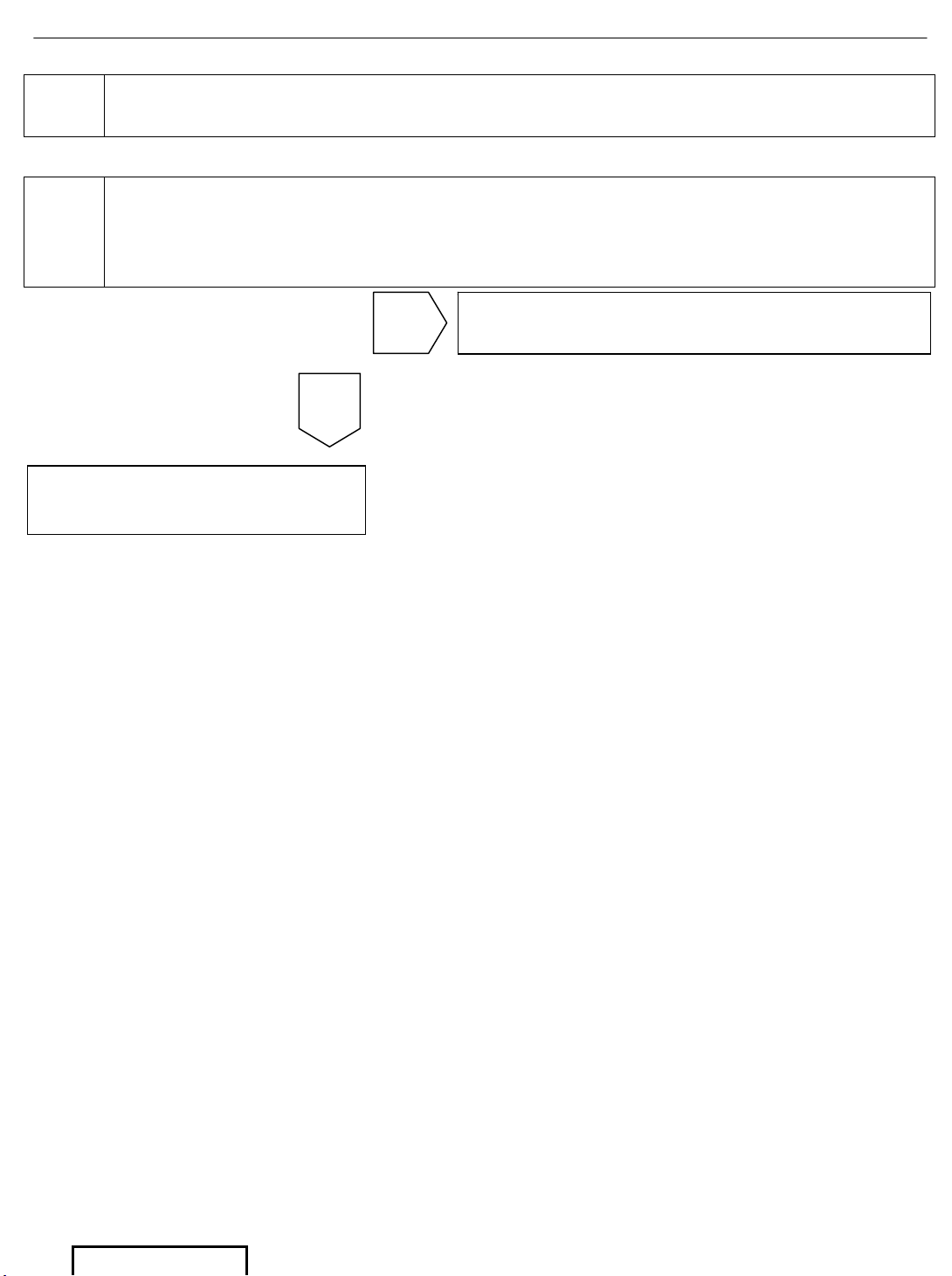
4
Check the Audio using a pair of Wired Headphones. NOTE
: Wired
Headphone Jacks are located on the front of the DVD Player
5
Disconnect P12 and P103, Verify continuity between each pin of the
connectors.
OK
Go to step Replace DVD Player
NG
Replace FPD
(IR Transmitter not working
properly).
OK
The harness from the DVD player to the
FM Modulator is defective.
Replace the RSE Main Wire Harness.
NG
Replace FPD
(IR Transmitter not working
properly).
Page 18
DVD Diagnostics - 17
Page 17 of 38 pages Supplier Ref #: DIO
Issue: A 01/12/04
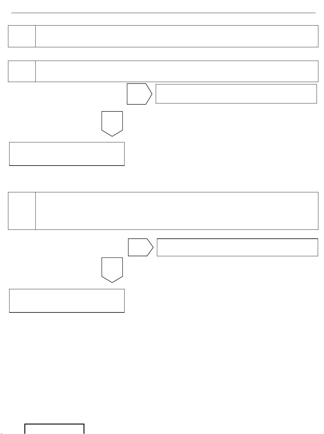
B7 SYMPTOM: No Audio on Wired Headphones
1
Verify that the System Audio is not muted. Press the Mute button on
the Remote Control and the screen will display if the system is muted
or not
2 Check Audio on Wireless IR Headphones.
3
Check both Headphone Jacks, on the DVD Console, with an alternate
Wired Headphone
Go to step
Turn OFF Mute mode
NG
OK
Go to step Go to SYMTOM B6
NG
OK
Go to step Replace DVD player
NG
OK
Original Wired Headphone
is not functioning properly.
Replace Headphones.
End.
Page 19
DVD Diagnostics - 18
Page 18 of 38 pages Supplier Ref #: DIO
Issue: A 01/12/04
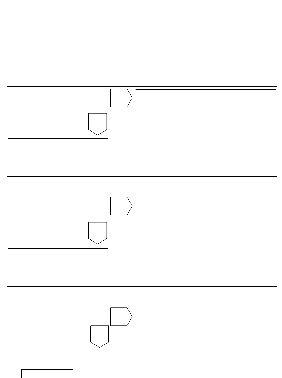
B8 SYMPTOM: DVD plays disc, but will not Eject
1
With the ignition switch in the ACC/ON position. Power System ONOFF-ON with the Remote Control or by pressing the Power button on
the DVD Player and then Stop, to stop the playback of the Disc, then
Press Eject.
Go to step
Replace DVD Player
NG
End.
System functions properly
OK
Page 20
DVD Diagnostics - 19
Page 19 of 38 pages Supplier Ref #: DIO
Issue: A 01/12/04
B9
SYMPTOM: DVD Player will not accept Disc, but the TOYOTA
Logo appears on the screen
1
Verify that the Disc is inserted properly. The label of the disc should be
facing the driver upon insertion into the DVD slot.
2
With the ignition switch in the ACC/ON position. Power System ONOFF-ON with the Remote Control or by pressing the Power button on
the DVD Player and then Stop, to stop the playback of the Disc, then
Press Eject.
OK
Go to step Go to step 2
NG
End.
System functions properly
Go to step
Replace DVD Player
End.
System functions properly
OK
Page 21
DVD Diagnostics - 20
Page 20 of 38 pages Supplier Ref #: DIO
Issue: A 01/12/04
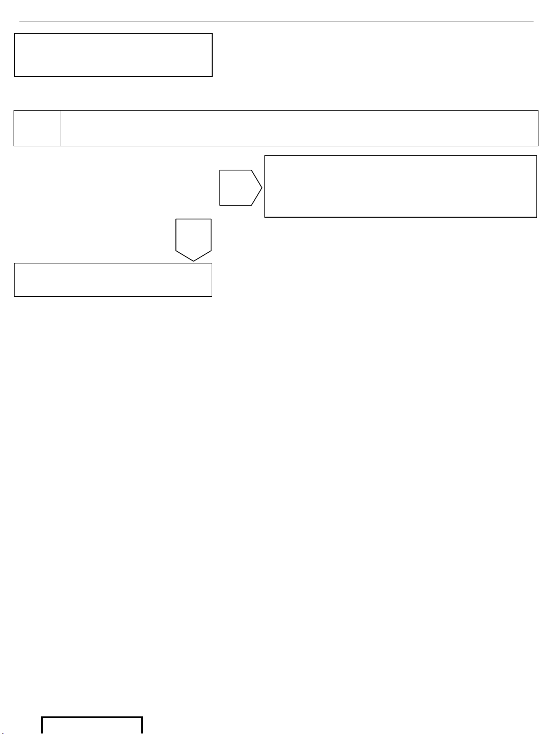
B10
SYMPTOM: DVD System will not respond to the Remote
Control. TOYOTA Logo appears on the screen or DVD disc
auto starts or displays Disc Menu when the IGN/ACC is ON
1
Check that the remote control can select DVD and AUX modes and all
other button functions. After pressing the Source button on the
Remote Control, either DVD or AUX will be displayed on the screen.
2 Install a New Battery in the Remote Control and Re-test
3 Try control functions of New Remote Control.
OK
Go to step Go to step 2
NG
OK
Go to step Go to step 3
NG
System functions properly
OK
Go to step Go to step 4
NG
System functions properly
Page 22
DVD Diagnostics - 21
Page 21 of 38 pages Supplier Ref #: DIO
Issue: A 01/12/04
4
Disconnect P12 and P103. Verify continuity between each pin of the
connectors.
Original Remote Control did
not function properly.
OK
Replace the FPD
Go to step
The harness from the DVD Player to the
FPD is defective.
NG
Page 23
DVD Diagnostics - 22
Page 22 of 38 pages Supplier Ref #: DIO
Issue: A 01/12/04
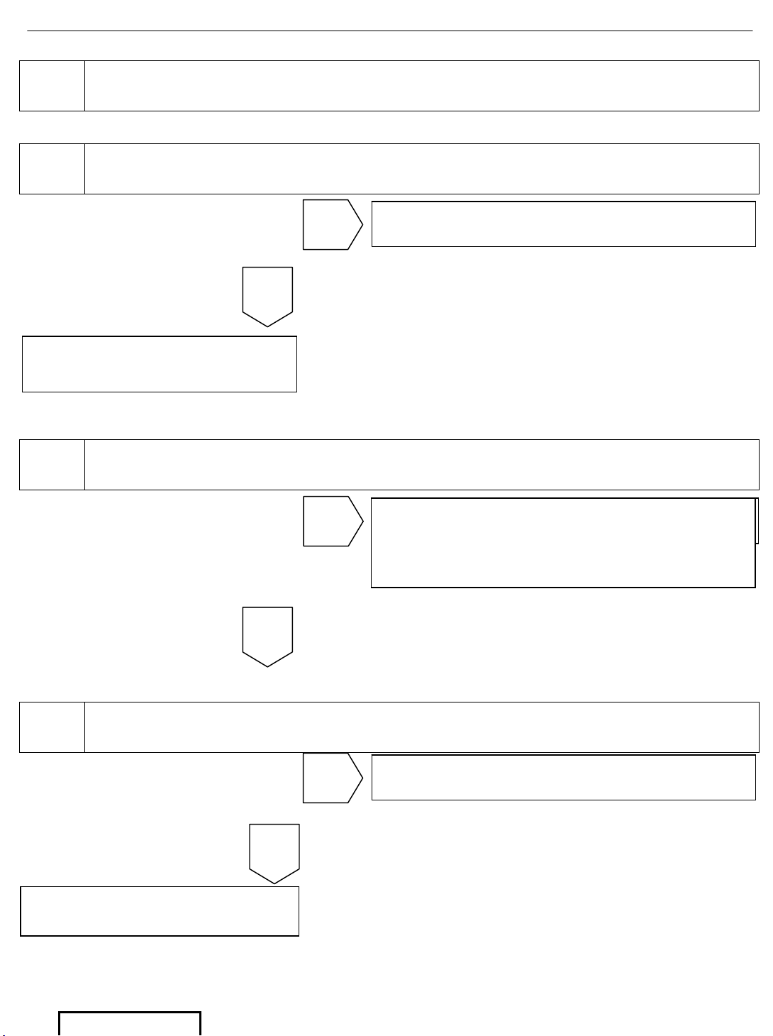
B11 SYMPTOM: The Dome Light in the FPD does not work
1
Switch the Dome Light Rocker Switch to the ON position and the Dome
Light turns ON
2
Remove the Dome Light Cover and verify that the Dome Light Bulb is
properly inserted into the Bulb Socket
3 Remove and Replace the Dome Light Bulb
OK
Go to step Go to step 2
NG
OK
Go to step
Either the bulb was inserted improperly
or the bulb was not inserted at all. Reinsert bulb and Re-test
NG
Dome Light works properly.
End.
OK
Go to step Go to step 4
NG
Dome light works, first bulb
was defective
Page 24
DVD Diagnostics - 23
Page 23 of 38 pages Supplier Ref #: DIO
Issue: A 01/12/04
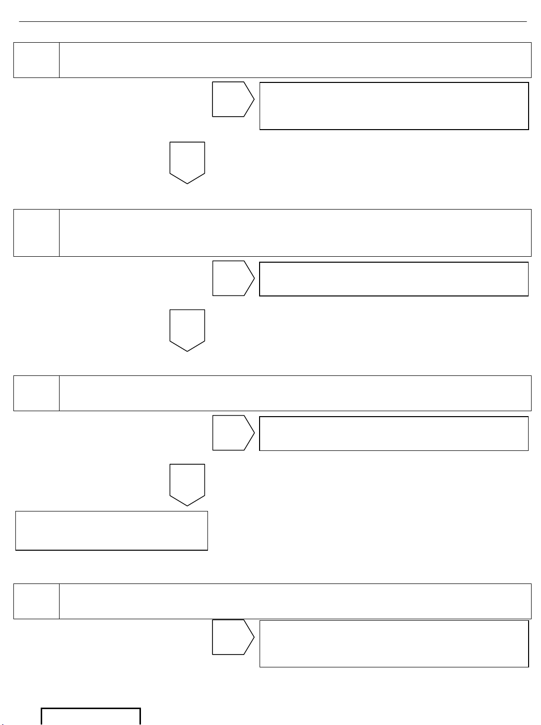
4 Check the 10 Amp Dome Light Fuse
5
Disconnect the FPD to expose the Dome Light Wire Harness. Verify
that the Dome Light Wire Harness is properly connected to the vehicle
Main Wire Harness
6
Disconnect the Dome Light connector and verify that +12 VDC exists on
Pins 1 and 2 and continuity to ground on Pin 3
7 Verify Battery Voltage is approximately 12 VDC.
OK
Go to step
Connect Dome Light Harness to Vehicle
Main Wire Harness and Re-test
NG
Go to step
Battery Discharged. Re-charge Battery.
Re-test.
NG
OK
Go to step
Go to step 7
NG
Dome Light Circuit is
defective. Replace FPD
OK
Go to step
Replace Fuse and Retest
NG
Page 25
DVD Diagnostics - 24
Page 24 of 38 pages Supplier Ref #: DIO
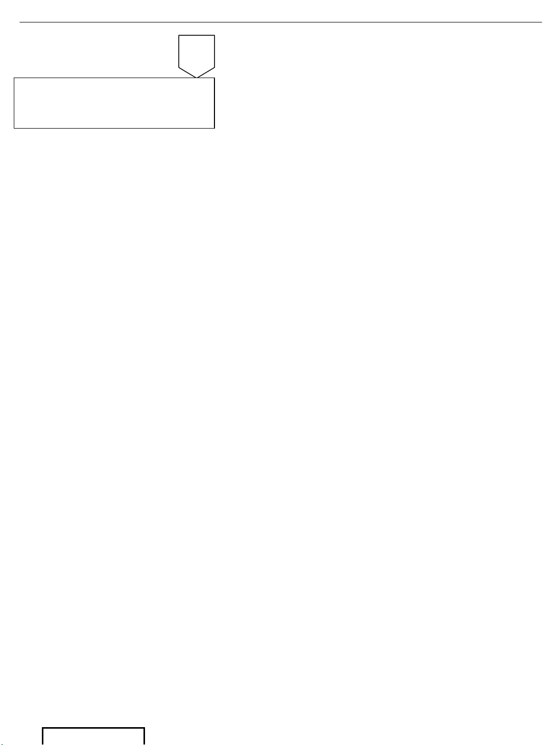
Issue: A 01/12/04
OK
Vehicle Main Wire Harness
is defective. Replace
Harness
Page 26
DVD Diagnostics - 25
Page 25 of 38 pages Supplier Ref #: DIO
Issue: A 01/12/04
B12
SYMPTOM: DVD disc will not resume last position after the
vehicle has been turned OFF and then turned ON again
This symptom concentrates on the B+ Input Power Line. While in the middle of disc Playback, the
vehicle is shut OFF, the DVD Players Memory will mark the last position of the disc and will
resume Playback from that point upon power up.
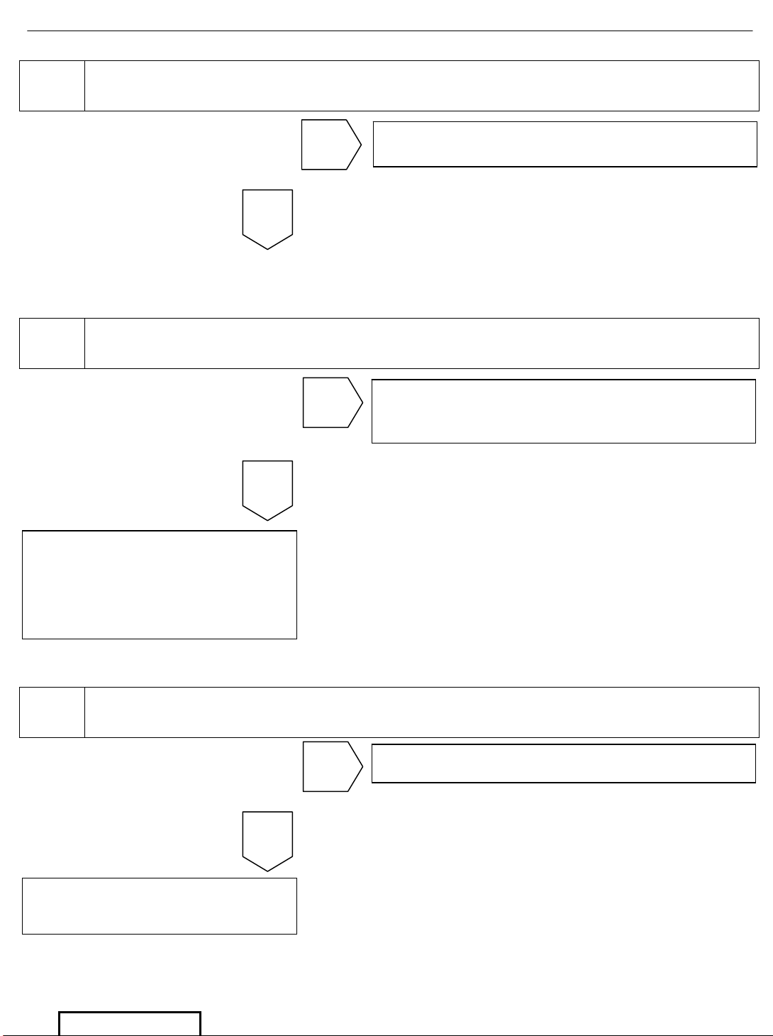
1
Power up the RSE System. Insert a disc into the DVD Player. Skip
forward two chapters into the video by pressing the next button twice
on the remote control. Shut off the vehicle and wait 5 seconds. Turn
the vehicle back ON. The video should resume from the point where
the video last left off.
2 Check the Vehicle Radio #2 Fuse (25 Amp)
3
For 8 Speaker System: Check B+ voltages on Pins 1 of J303
For 6 Speaker System: Check B+ voltages on Pins 4 of J305
OK
Go to step Go to step 2
NG
End.
System functions properly
OK
Replace Fuse and Re-test
NG
OK
Check Vehicle Main Wire Harness
NG
Page 27
DVD Diagnostics - 26
Page 26 of 38 pages Supplier Ref #: DIO
Issue: A 01/12/04
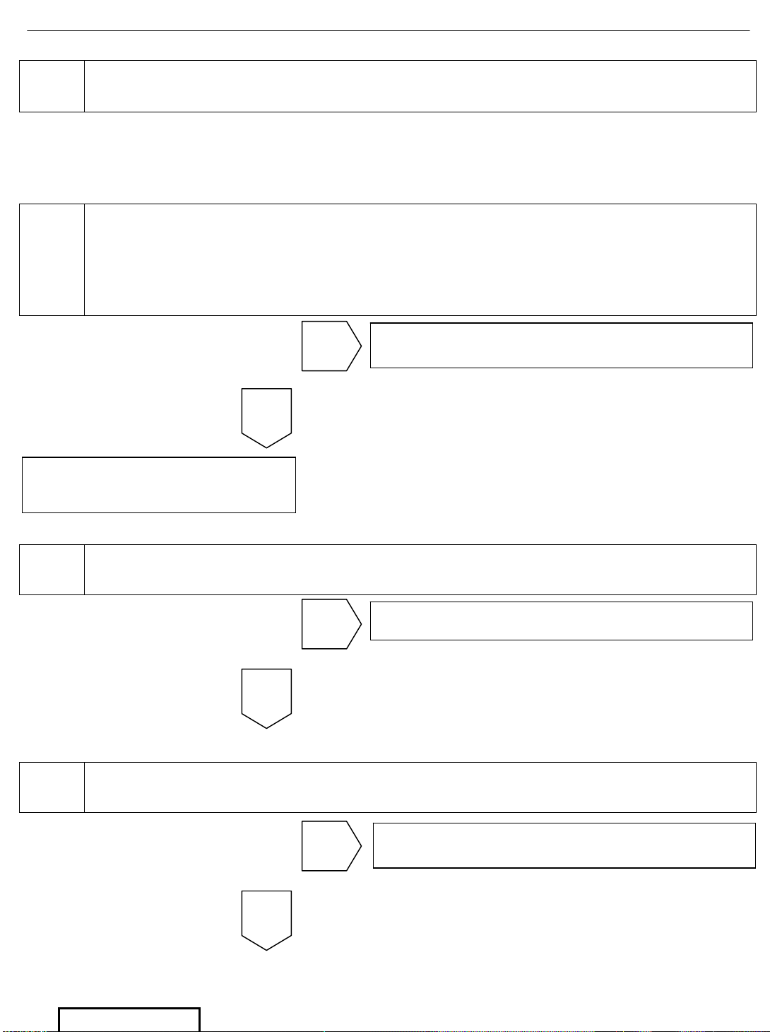
4 Check the B+ voltage on Pin 1 of connector P13
5 Check the B+ voltage on Pin 2 of connector P21
6 Check the 5 Amp fuses on the T-Harness
OK
Go to step 6
NG
OK
Go to step
Replace RSE Main Wire Harness.
Harness is defective
NG
End.
Replace DVD Player.
DVD Player not functioning
properly
OK
Replace fuse (s) and Re-test
NG
Replace T-Harness and
Re-test
Page 28
DVD Diagnostics - 27
Page 27 of 38 pages Supplier Ref #: DIO
Issue: A 01/12/04
RSE Main Component Layout
Figure 1. RSE Main Component Layout (Non-Sunroof)
Page 29
DVD Diagnostics - 28
Page 28 of 38 pages Supplier Ref #: DIO
Issue: A 01/12/04
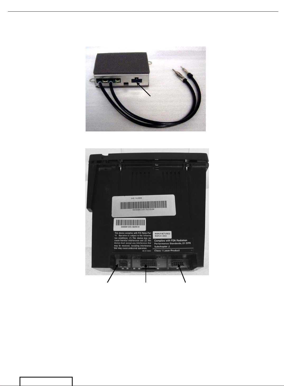
Connection Locations on the FM Modulator and DVD Player
Figure 2. FM Modulator Connections
Figure 3. DVD Player Connections
P307
P21
P12 P20
Page 30
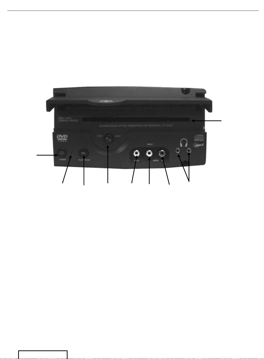
DVD Diagnostics - 29
Page 29 of 38 pages Supplier Ref #: DIO
Issue: A 01/12/04
Figure 4. DVD Player Front Face Plate
DISC Slo
t
Power
Button
Status
Indicator
Light
PLAY/
PAUSE
STOP/
EJECT
Video
Input
Audio
Left
Input
Audio
Right
Input
Wired
Headphone
Jacks
Page 31
DVD Diagnostics - 30
Page 30 of 38 pages Supplier Ref #: DIO
Issue: A 01/12/04
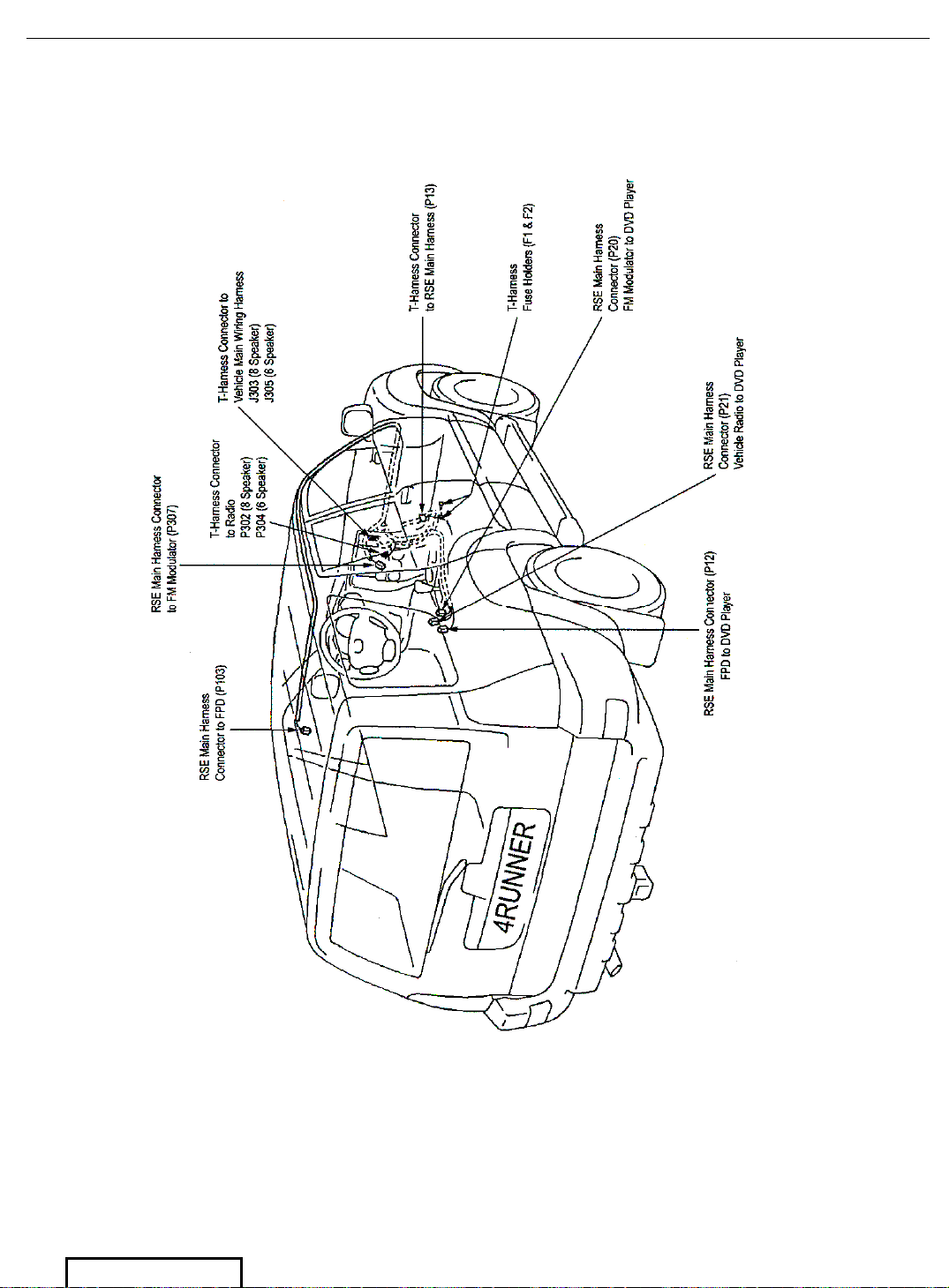
RSE Wire Harness/Connector Location
(Non-Sunroof)
Figure 5. RSE Connector/Wire Harness Location
Page 32
DVD Diagnostics - 31
Page 31 of 38 pages Supplier Ref #: DIO
Issue: A 01/12/04
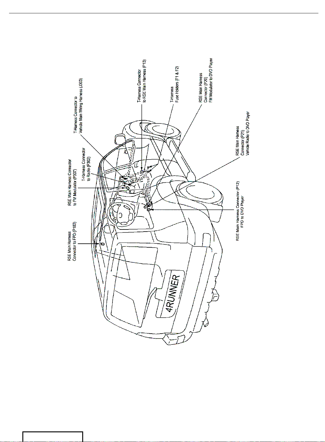
RSE Wire Harness/Connector Location
(Sunroof)
Figure 6. RSE Connector/Wire Harness Location
Page 33
DVD Diagnostics - 32
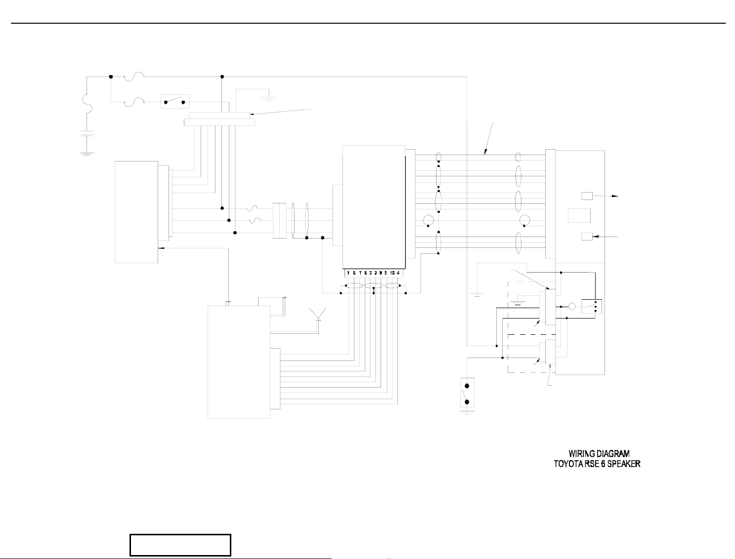
RSE Wire Diagram (6 Speaker)
RADIO No.2 25A (B+)
MAIN
RADIO No.1 7.5A (Acc)z
FUSE
VEHICLE WIRE HARNESS
BATTERY
STANDARD
RADIO
6 SPEAKER
ANTENNA
INPUT
P304
7346521
J305
P12
1
2
1
2
5
6
4
3
F1
5A
5A
F2
7
J14
1
1
3
3
2
2
P13
GND
P21
B+
2
Acc
1
3
6
DVD
3
4
5
6
8
9
10
7
14
11
12
13
P20
DIVERSITY
P307
FMM
1
6
7
8
3
2
9
5
10
4
POWER-7.5V
GND
GND
FM-CE
FM-DA
FM-CK
D-GND
AUDIO-R
AUDIO-L
A-GND
DOOR
SWITCH
SW-GND-DOME
RING
GND
POWER-DOME
UP PILLAR "A"
3-PIN MALE
CONNECTOR
POWER-7.5V
375N
GND-DOME
EXISTING
3-PIN FEMALE
CONNECTOR
722N
EXISTING
2-PIN FEMALE
CONNECTOR
P103
GND
IR-GND
IR-IN
IR-5V
D-GND
D-TXD
D-RXD
D-ACK
VIDEO
V-GND
A-GND
AUDIO-R
AUDIO-L
GND-DOME
3
1
2
1
2
1
2
3
4
5
6
8
9
10
7
14
11
12
13
DOMELIGHT
2-PIN MALE
CONNECTOR
DISPLAY
(FPD)
Tx
Rx
IR FOR
WIRELESS
REMOTE
EYE
CONNECTORS/NOTES
1. J14=(3 PIN)
2. P13= (3 PIN)
3. P12=(14 PIN)
4. P103= (14 PIN)
5. P20= (10 PIN)
6. P21= ( 6 PIN)
7. P307=(10 PIN)
8. J305= (10 PIN)
9. P304= (10 PIN)
Figure 7. RSE Wire Diagram (6 Speaker)
Page 32 of 38 pages Supplier Ref #: DIO
Issue: A 01/12/04
Page 34
MAIN
FUSE
DVD Diagnostics - 33
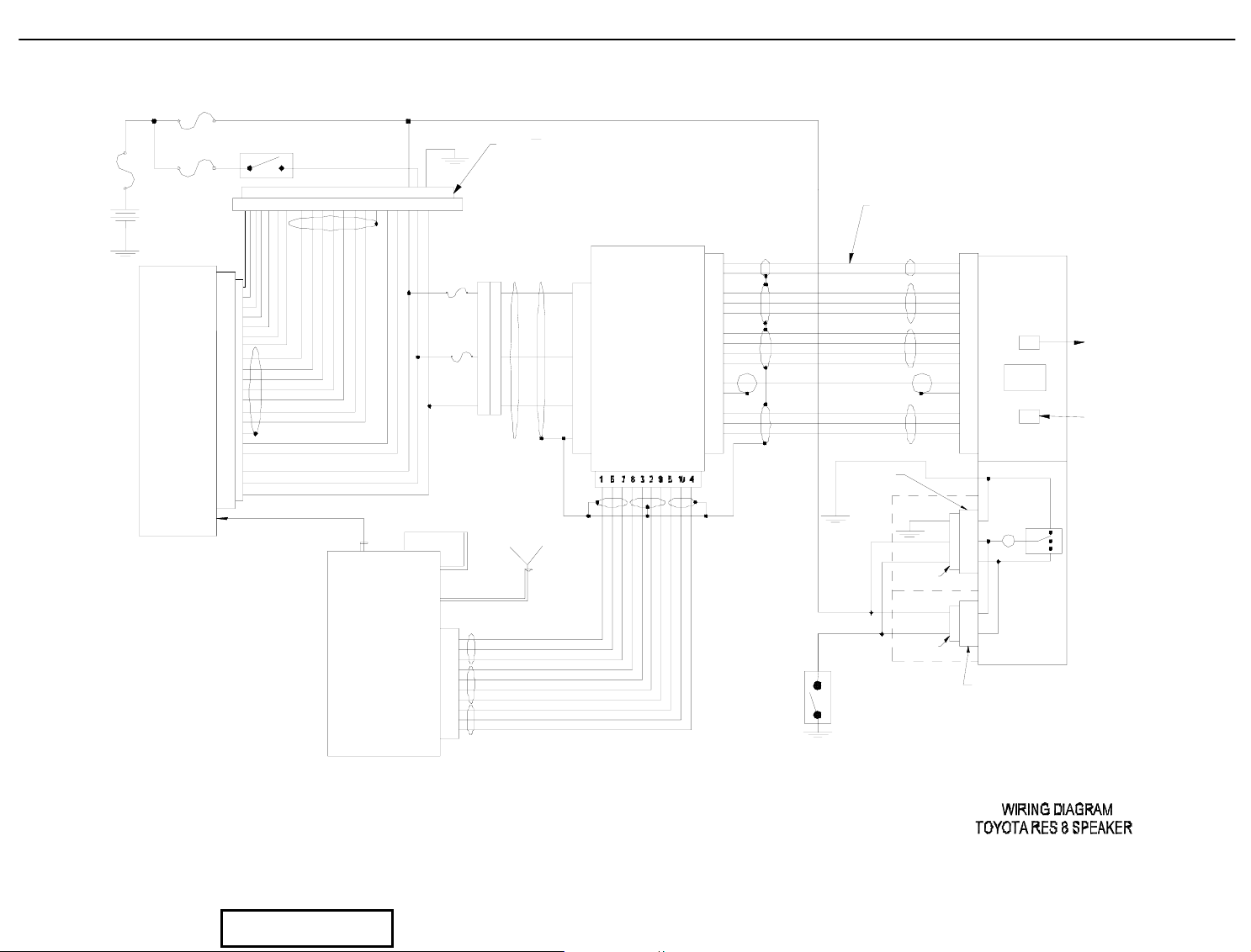
RSE Wire Diagram (8 Speaker)
RADIO No.2 25A (B+)
RADIO No.1 7.5A (Acc)z
BATTERY
STANDARD
RADIO
8 SPEAKER
ANTENNA
INPUT
CONNECTORS
1. J14= (3 PIN)
2. P13= (3 PIN)
3. P12= (14 PIN)
4. P103= (14 PIN)
5. P20= (10 PIN)
6. P21= ( 6 PIN)
7. P307= (10 PIN)
8. J303= (20 PIN)
9. P302= (20 PIN)
P302
2
4
5
6
12
14
15
9
8
19
18
16
7
17
10
3
13
1
11
20
VEHICLE WIRE HARNESS
151412654
9819
18
2
1667217
10
FMM
313
111 20
F1
5A
F2
DIVERSITY
1
6
7
8
3
2
9
5
10
4
5A
J303
11
33
22
P13
P307
J14
B+
Acc
GND
POWER-7.5V
GND
GND
FM-CE
FM-DA
FM-CK
D-GND
AUDIO-R
AUDIO-L
A-GND
P21
P20
UP PILLAR "A"
P12
1
2
3
4
5
6
8
1
DVD
3
9
10
7
14
11
12
13
3-PIN MALE
CONNECTOR
RING
GND
POWER-7.5V
375N
GND-DOME
P103
GND
IR-GND
IR-IN
IR-5V
D-GND
D-TXD
D-RXD
D-ACK
VIDEO
V-GND
A-GND
AUDIO-R
AUDIO-L
GND-DOME
1
2
3
4
5
6
8
9
10
7
14
11
12
13
3
DISPLAY
(FPD)
Tx
Rx
DOMELIGHT
IR FOR
WIRELESS
REMOTE
EYE
1
2
EXISTING
3-PIN FEMALE
CONNECTOR
722N
EXISTING
2-PIN FEMALE
CONNECTOR
1
2
DOOR
SWITCH
POWER-DOME
SW-GND-DOME
Figure 8. RSE Wire Diagram (8 Speaker)
Page 33 of 38 pages Supplier Ref #: DIO
Issue: A 01/12/04
Page 35
DVD Diagnostics - 34
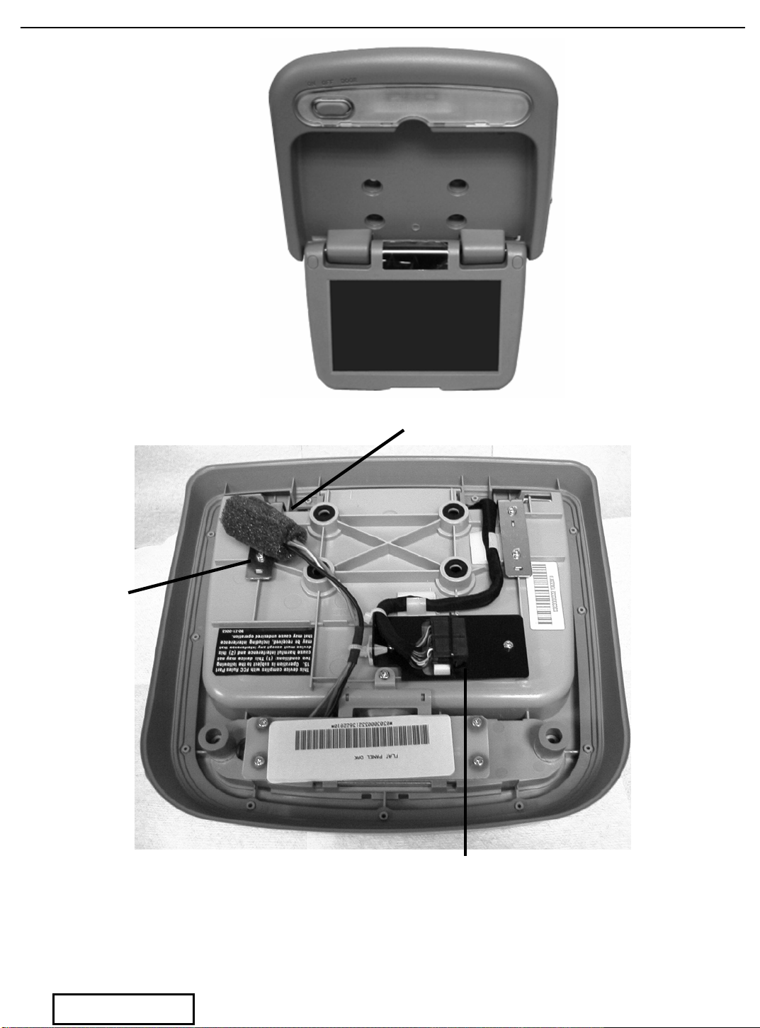
Dome Light
Connector
Page 34 of 38 pages Supplier Ref #: DIO
Issue: A 01/12/04
FPD
FPD / IR
Connector
Figure 9 FPD Connector Locations
Page 36
DVD Diagnostics - 35
A
A
A
A
A
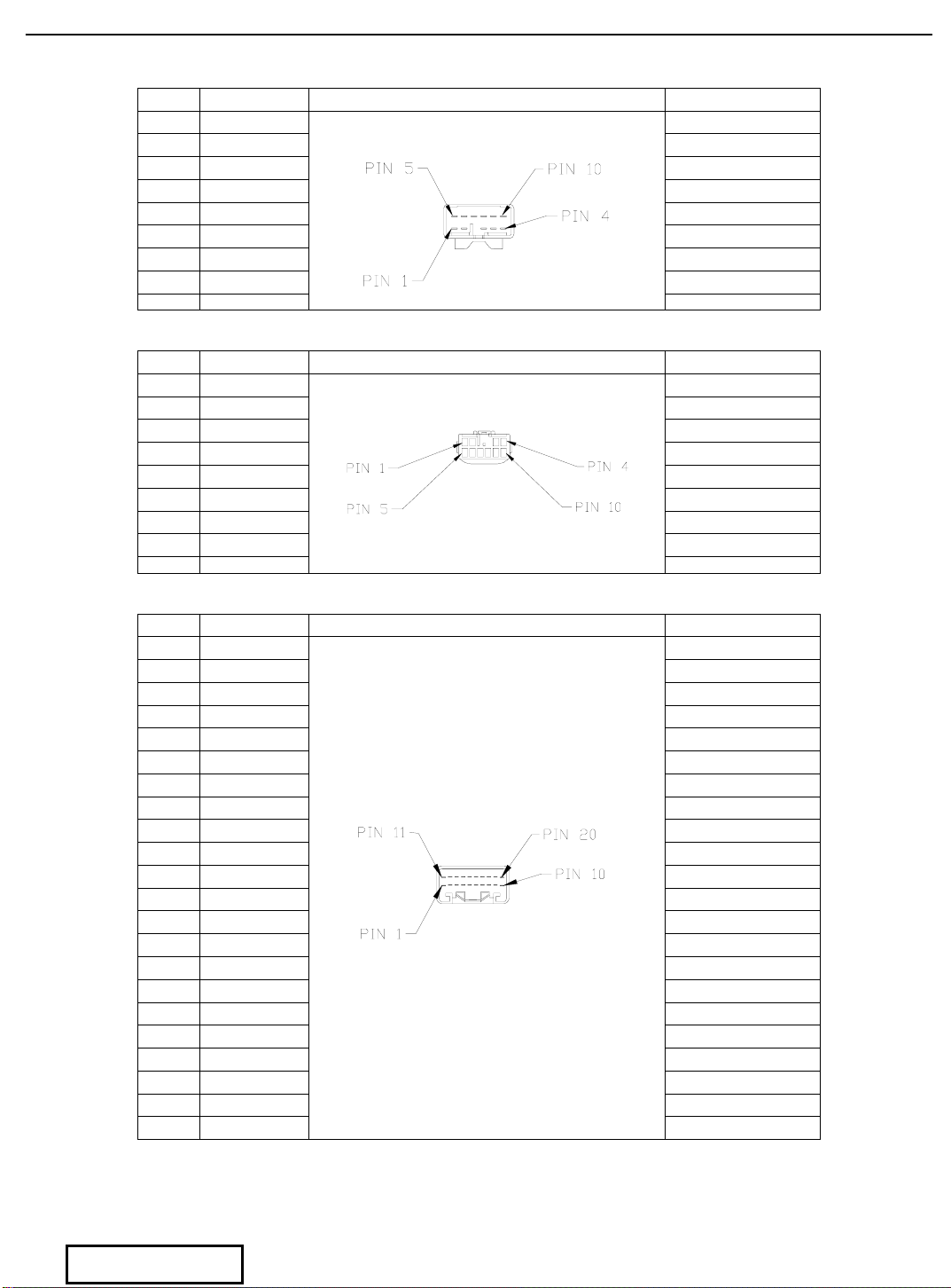
Connector Tables
PIN # Function Connector # J305 Color/Gauge
1 FR+ Brown 20#
2 FL+ Green 20#
3
4 B+ White 20#
5 FR- Yellow 20#
6 FL- Blue 20#
7 GND
CC Red 20#
PIN # Function Connector # P304 Color/Gauge
1 FR+ Brown 20#
2 FL+ Green 20#
3
4 B+ White 20#
5 FR- Yellow 20#
6 FL- Blue 20#
7 GND
CC Red 20#
PIN # Function Connector # J303 Color/Gauge
1 B+ White 20#
2 - White/Black 20#
3
4 - White/Red 20#
5
6 - White/Green 20#
7 MUTE Brown 20#
8 FR Red 20#
9 FL Yellow 20#
10 SGDE Shield
11
12 - White/Yellow 20#
13
14 - White/Blue 20#
15 - White/Orange 20#
16 SGND Black 20#
17 BEEP Orange 20#
18 RR Green 20#
19 RL Blue 20#
20 GND
MP Violet 20#
CC Red 20#
NT Gray 20#
6 speaker T-harness (Power End)
Black 20#
6 speaker T-harness (Radio End)
Black 20#
8 speaker T-harness (Power End)
Black 20#
Page 35 of 38 pages Supplier Ref #: DIO
Issue: A 01/12/04
Page 37
DVD Diagnostics - 36
A
A
A
A
A
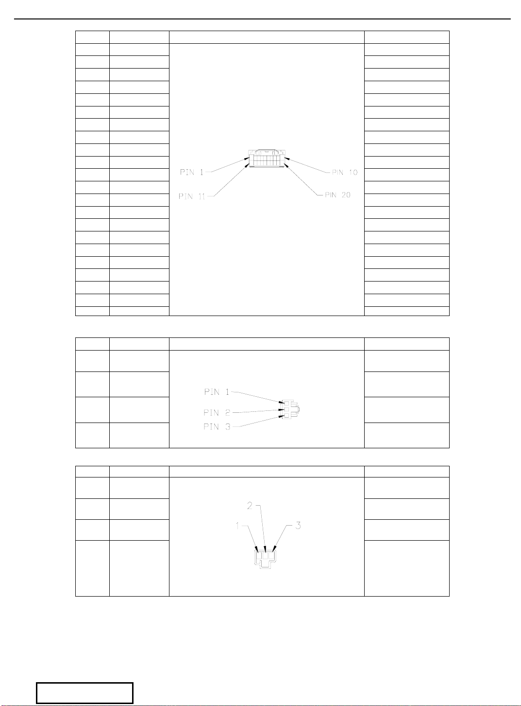
PIN # Function Connector # P302 Color/Gauge
1 B+ White 20#
2 - White/Black 20#
3
4 - White/Red 20#
5
6 - White/Green 20#
7 MUTE Brown 20#
8 FR Red 20#
9 FL Yellow 20#
10 SGDE Shield
11
12 - White/Yellow 20#
13
14 - White/Blue 20#
15 - White/Orange 20#
16 SGND Black 20#
17 BEEP Orange 20#
18 RR Green 20#
19 RL Blue 20#
20 GND
MP Violet 20#
CC Red 20#
NT Gray 20#
8 speaker T-harness (Radio End)
Black 20#
PIN # Function Connector P13 Color/Gauge
1 B+ White 20#
T-Harness to 6 & 8 Speaker Power
2 GND Black 20#
3
CC Red 20#
PIN # Function Connector J14 Color/Gauge
1 B+ White 20#
2 GND Black 20#
3
CC Red 20#
T-Harness Power to DVD Power
Page 36 of 38 pages Supplier Ref #: DIO
Issue: A 01/12/04
Page 38
DVD Diagnostics - 37
A
A
A
A
A
A
A
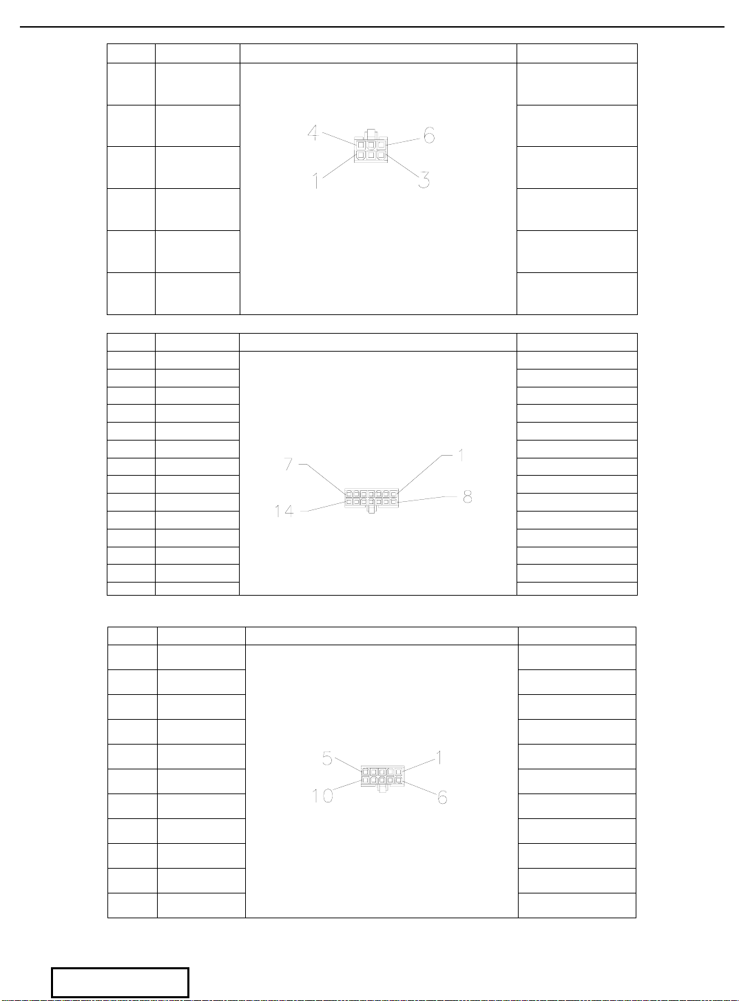
PIN # Function Connector P21 Color/Gauge
Power to DVD
1
2 B+ White 20#
3 GND Black 20#
4 NC
5 NC
CC Red 20#
6 GND
Drain
PIN # Function Connector P12, P103 Color/Gauge
1 POWER-7.5V Red 20#
2 GND Black 20#
3 IR-GND Black 26#
4 IR-IN Brown 26#
5 IR-5V Red 26#
6 D-GND Black 26#
7 VIDEO Coax, conductor
8 D-TXD Brown 26#
9 D-RXD Red 26#
10 D-ACK Orange 26#
11
12
13
14 V-GND
-GND Black 26#
UDIO-R Red 26#
UDIO-L Brown 26#
DVD to FPD
Coax, shield
PIN # Function Connector P20, P307 Color/Gauge
1 Power-7.5V Red 20#
2 FM-CK Red 24#
DVD to FM Modulator
3 FM-DA White 24#
4
5
6 GND Black 20#
7 GND White 20#
8 FM-CE Green 24#
9 D-GND Black 24#
10
-GND Black 24#
UDIO-R Red 24#
UDIO-L White 24#
Page 37 of 38 pages Supplier Ref #: DIO
Issue: A 01/12/04
Page 39
DVD Diagnostics - 38
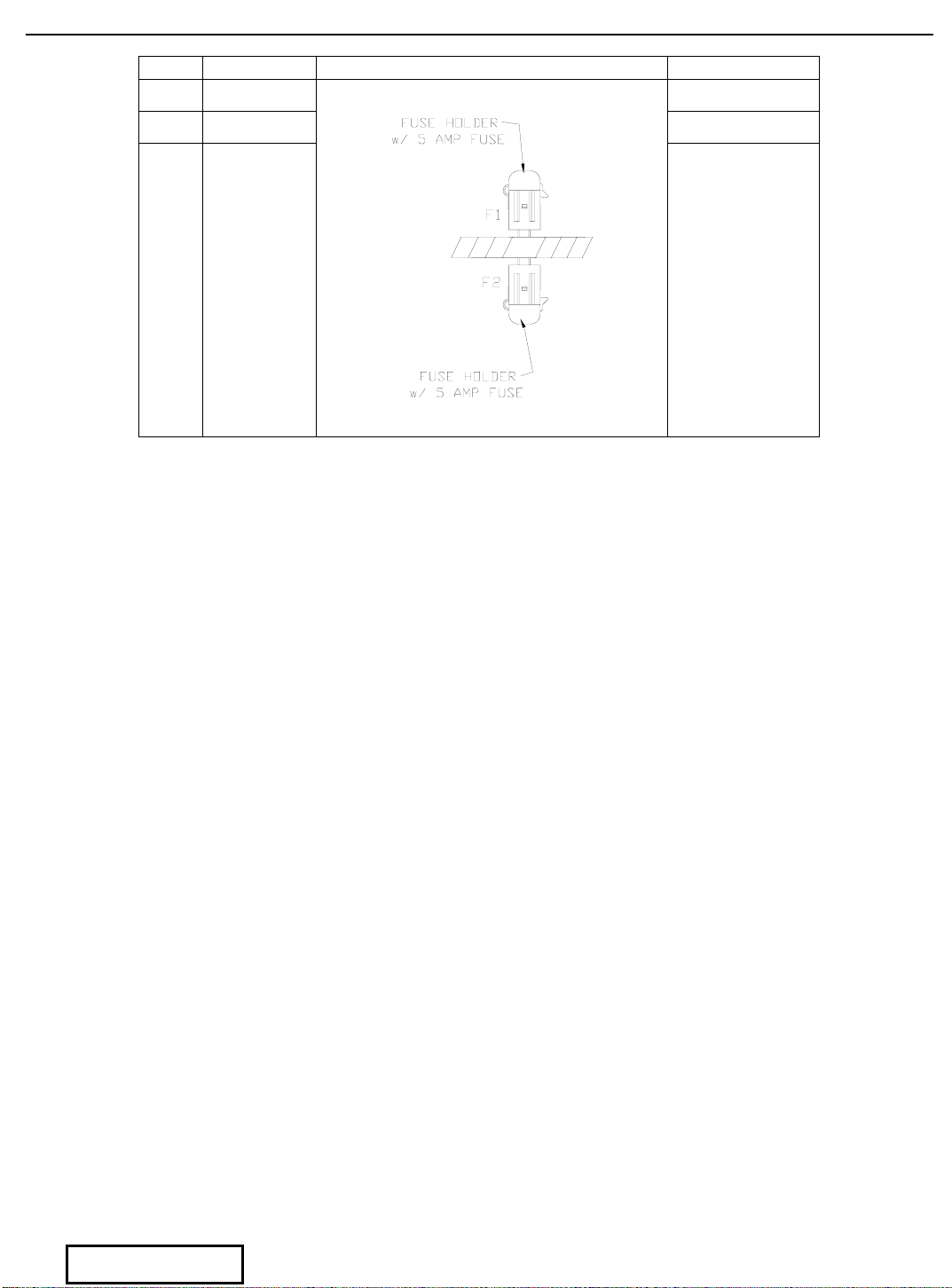
PIN # Function Connector P20, P307 Color/Gauge
F1-A Power B+ White 20#
F2-A Power ACC Red 20#
Power and Memory Fuses
Page 38 of 38 pages Supplier Ref #: DIO
Issue: A 01/12/04
 Loading...