

Page 1
’02 4Runner_U (L/O 0108)
i
2002 MY 4RUNNER_U (OM35787U)
Foreword
Welcome to the growing group of value–conscious people who drive Toyotas. We are proud of the advanced engineering and
quality construction of each vehicle we build.
This Owner’s Manual explains the operation of your new Toyota. Please read it thoroughly and have all the occupants
follow the instructions carefully. Doing so will help you enjoy many years of safe and trouble–free motoring. For
important information about this manual and your Toyota, read the following pages carefully.
When it comes to service, remember that your Toyota dealer knows your vehicle best and is interested in your complete
satisfaction. He will provide quality maintenance and any other assistance you may require.
If there is not a Toyota dealer near you, or you need emergency assistance for any reason, please call the following number:
U.S. OWNERS: Toyota Cust omer Assist ance Center Toll–free:1–800–331–4331
CANADIAN OWNERS: Toyota Canada Cust omer Interact ion Centre Toll–free:1–888–TOYOTA–8 (1–888–869–6828)
Please leave this Owner’s Manual in this vehicle at the time of resale. The next owner will need this information also.
All information and specifications in this manual are current at the time of printing. However, because of Toyota’s policy of
continual product improvement, we reserve the right to make changes at any time without notice.
Please note that this manual applies to all models and explains all equipment, including options. Therefore, you may
find some explanations for equipment not installed on your vehicle.
2001 TOYOTA MOTOR CORPORATION
All ri ghts reserved. T his material m ay not be repr oduced or copied, in whole or i n part, without the writt en permission of Toyota
Motor Corporat ion.
Page 2
’02 4Runner_U (L/O 0108)
ii
2002 MY 4RUNNER_U (OM35787U)
Important information about this manual
Safety and vehicle damage warnings
Throughout this manual, you will see safety and vehicle damage warnings. You must follow these warnings carefully to
avoid possible injury or damage.
The types of warnings, what they look like, and how they are
used in this manual are explained as follows:
CAUTION
This is a warning against something which may cause
injury to people if the warning is ignored. You are
informed about what you must or must not do in
order to avoid or reduce the risk to yourself and other
people.
NOTICE
This is a warning against something which may cause
damage to the vehicle or its equipment if the warning
is ignored. You are informed about what you must or
must not do in order to avoid or reduce the risk of
damage to your vehicle and its equipment.
Safety symbol
When you see the safety symbol
shown above, it means: “Do not...”;
“Do not do this”; or “Do not let this
happen”.
Page 3

’02 4Runner_U (L/O 0108)
iii
2002 MY 4RUNNER_U (OM35787U)
Important information about your Toyota
New vehicle warranty
Your new vehicle is covered by the following Toyota limited
warranties :
New vehicle warranty
Emission control systems warranty
Others
For further information, please refer to the “Owner’s
Warranty Information Booklet” or “Owner’s Manual
Supplement”.
Your responsibility for
maintenance
It is the owner’s responsi bility to make sure that the specified maintenance is performed. Section 6 gives details of
these maintenance requirements. Also included in Section
6 is general maintenance. For scheduled maintenance information, please refer to the “Scheduled Maintenance
Guide” or “Owner ’s Manual Supplement” .
Accessories, spare parts and
modification of your Toyota
A wide variety of n on–genuine spare parts a nd accessori es
for Toyota vehicles are currently available in the market.
You should know that Toyota does not warrant t hese products and is not responsibl e for their performance, r epair, or
replacement, or for any damage they may cause to, or
adverse effec t they may have on, your Toyota vehicl e.
This vehicle should not be modified with non–genuine
Toyota products. Modification with non–genuine Toyota
products could affect its performance, safety or durability,
and may even violate governmental regulations. In addition, damage or performance problems resulting from the
modificat ion may not be covered under war ranty.
Page 4

’02 4Runner_U (L/O 0108)
iv
2002 MY 4RUNNER_U (OM35787U)
Spark ignition system of your
Toyota
The spark ignit ion system in your Toyota meets all requirements of the Canadian Interference–Causing Equipment
Standard.
Installation of a mobile
two–way radio system
As the installation of a mobile two–way radio system in
your vehic le could affect el ectronic s ystems suc h as multiport fuel inject ion system/sequenti al multiport fuel injec tion
system, traction control system (two–wheel drive models)/active traction control system (four–wheel drive models), vehicle skid control system, cruise control system,
anti–lock brake system, electronic throttle control system,
SRS airbag syst em and seat belt pret ensioner system , be
sure to check with your Toyota dealer for precautionary
measures or special i nstructions r egarding installati on.
Page 5

’02 4Runner_U (L/O 0108)
v
2002 MY 4RUNNER_U (OM35787U)
Scrapping of your Toyota
The SRS airbag and s eat belt pret ensioner devi ces in y our
Toyota contain explosive chemicals. If the vehicle is
scrapped with the airbags and pretensioners left as they
are, it may cause an accident such as fire. Be sure to
have the systems of the SRS airbag and seat belt pretensioner removed and disposed of by a qualified service
shop or by your Toyota dealer before you dis pose of your
vehicle.
On–pavement and off–road
driving tips
This vehi cle belongs to the u tility vehicle class. Utility vehicles have a significantly higher rollover rate than other
types of vehicles. This vehicle will handle and maneuver
differently from an ordinary passenger car because it is
designed for off–road use also. In addition, this vehicle
has a higher ground clearance and center of gravity than
that of an ordi nary passenger car. This vehic le design feature causes this type of vehicle to be more likely to rollover. Failure to operate this vehicle correctly may result in
loss of control , accidents or vehi cle rollover causing death
or serious injur y. Be sure to read “Off–road vehic le precautions” in Section 2 and “Off–road driving precautions” in
Section 3.
Page 6

’02 4Runner_U (L/O 0108)
vi
2002 MY 4RUNNER_U (OM35787U)
Page 7
’02 4Runner_U (L/O 0108)
1
2002 MY 4RUNNER_U (OM35787U)
OPERATION O F INSTRUMENTS AND
CONTROLS
Overview of instruments and controls
Instrument panel overview 2. . . . . . . . . . . . . . . . . . . . . . . . . . . . . . . . . . . . .
Instrument cluster overview 5. . . . . . . . . . . . . . . . . . . . . . . . . . . . . . . . . . . .
Indicator symbols on the instrument panel 6. . . . . . . . . . . . . . . . . . . . . . .
SECTION 1–
1
Page 8
’02 4Runner_U (L/O 0108)
2
2002 MY 4RUNNER_U (OM35787U)
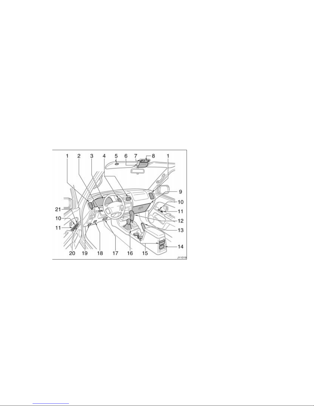
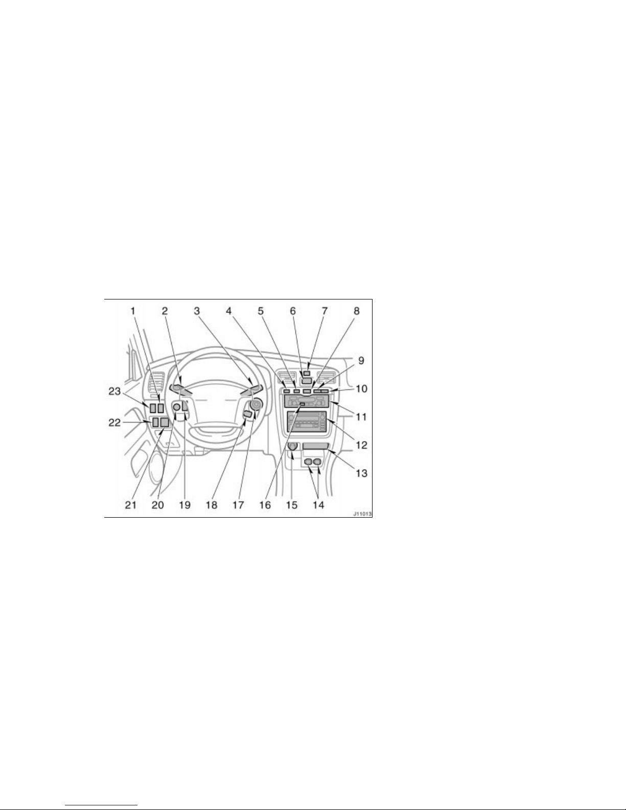
1. Side vents
2. Tilt steering loc k release lever
3. Instrument c luster
4. Center vents
5. Garage door opener
6. Garage door opener box or auxiliary
box
7. Electri c moon roof switch
8. Personal lights
9. Glove box
10. Power door lock switc hes
11. Power window swi tches
12. Automatic tr ansmission selec tor lever
13. Parking brak e lever
14. Ashtray
15. Cup holders
16. Front drive c ontrol lever
17. Lower vent
18. Hood lock releas e lever
19. Fuel filler door opener
20. Window lock swi tch
21. Power rear view mirror cont rol switches
(with power w indows)
Instrument panel overview
Page 9
’02 4Runner_U (L/O 0108)
3
2002 MY 4RUNNER_U (OM35787U)
1. Seat heater swit ch (for passenger)
2. Headlight and turn si gnal switch, and
front fog light swit ch
3. Wiper and washer swi tches
4. Back window and outside rear view
mirror def oggers switch
5. Driving pattern selector button
6. Clock
7. Emergency flas her switch
8. Power back window swit ch
9. Theft deterrent sy stem/Engine
immobiliser system indicator light
10. Front passenger ’s seat belt reminder
light
11. Air condit ioning controls
12. Car audio
13. Ashtray
14. Power outlets
15. Cigarette li ghter
16. “OUT/T” (out side temperature) butt on
17. Ignition swi tch
18. Cruise contr ol switch
19. Center different ial lock switc h
20. Instrument p anel light control k nob
21. Power rear view mirror cont rol switch
(without power wi ndows)
Page 10

’02 4Runner_U (L/O 0108)
4
2002 MY 4RUNNER_U (OM35787U)
22. Traction contr ol off switch
23. Seat heater swit ch (for driver) o r
Power back window loc k switch
Page 11
’02 4Runner_U (L/O 0108)
5
2002 MY 4RUNNER_U (OM35787U)
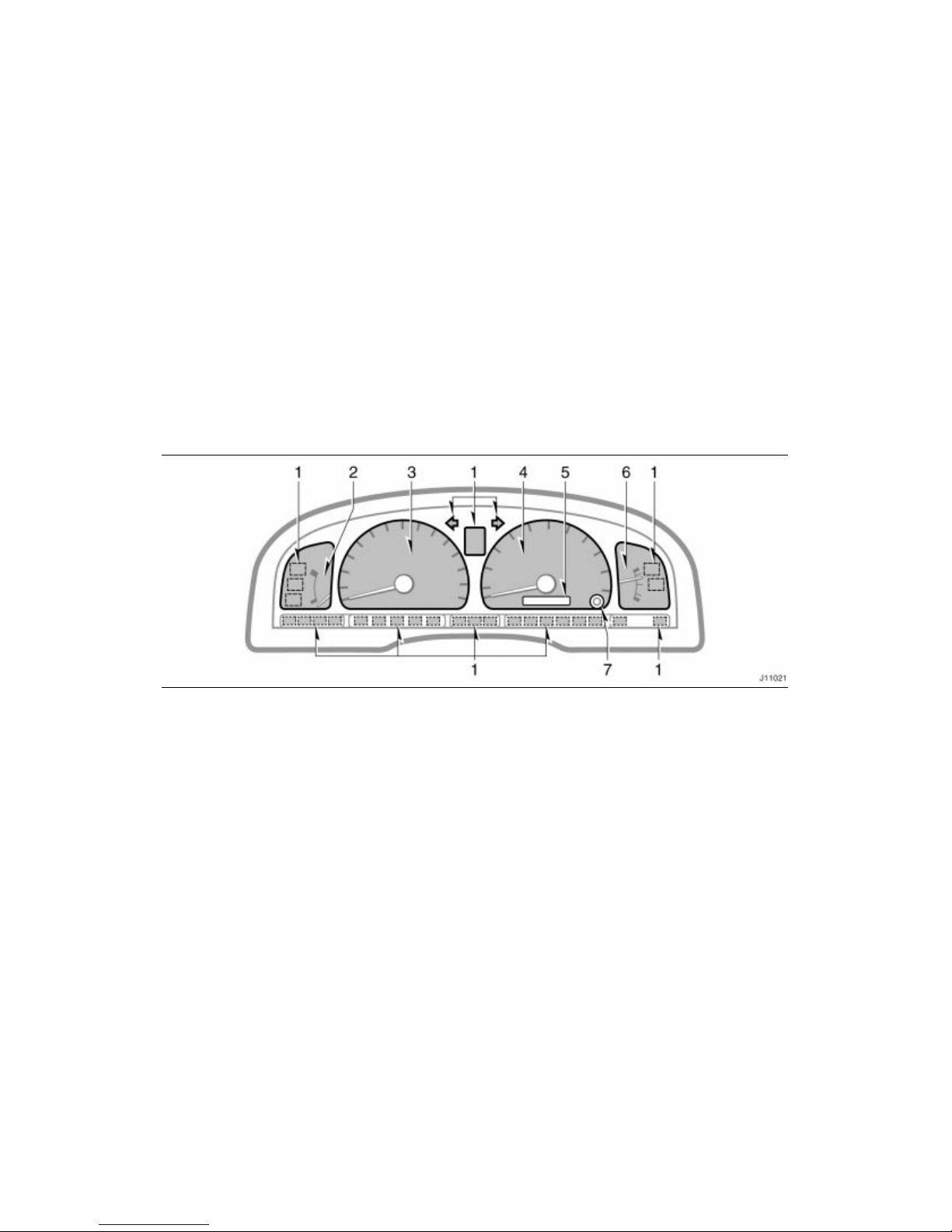
1. Service remi nder indicators and
indicator l ights
2. Engine coolant temper ature gauge
3. Tachometer
4. Speedometer
5. Odometer and two trip met ers
6. Fuel gauge
7. Trip met er reset knob
Instrument cluster overview
Page 12
’02 4Runner_U (L/O 0108)
6
2002 MY 4RUNNER_U (OM35787U)
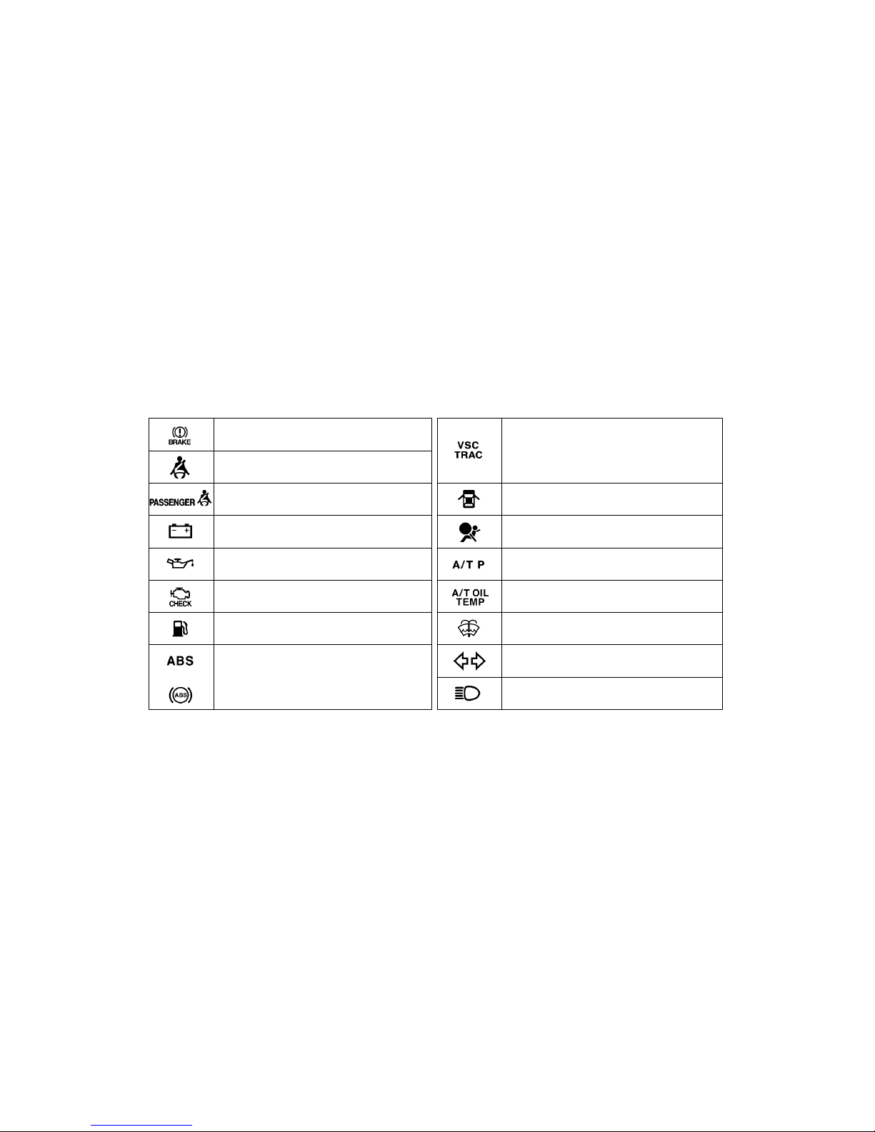
or
Driver’s seat belt reminder light
∗
1
Low engine oil pressure warning light
∗
1
Low fuel level warning light
∗
1
Brake system warning light
∗
1
Malfunction indicator lamp
∗
1
Discharge warning light
∗
1
Anti–lock brake system warning light
∗
1
Automatic t ransmission fl uid temperature
warning light
∗
1
SRS warning light
∗
1
Unengaged “Park” warning light
∗
1
Open door warning light
∗
1
Low windshield was her fluid level warning
light
∗
1
Headlight high beam indicator light
Turn signal indicator lights
Front passenger’s seat belt reminder light
∗
1
Vehicle skid cont rol system and trac tion control
system (two–wheel drive models) or ac tive
tracti on control system ( four–wheel drive models)
warning light
∗
1
Indicator symbols on the instrument panel
Page 13
’02 4Runner_U (L/O 0108)
7
2002 MY 4RUNNER_U (OM35787U)
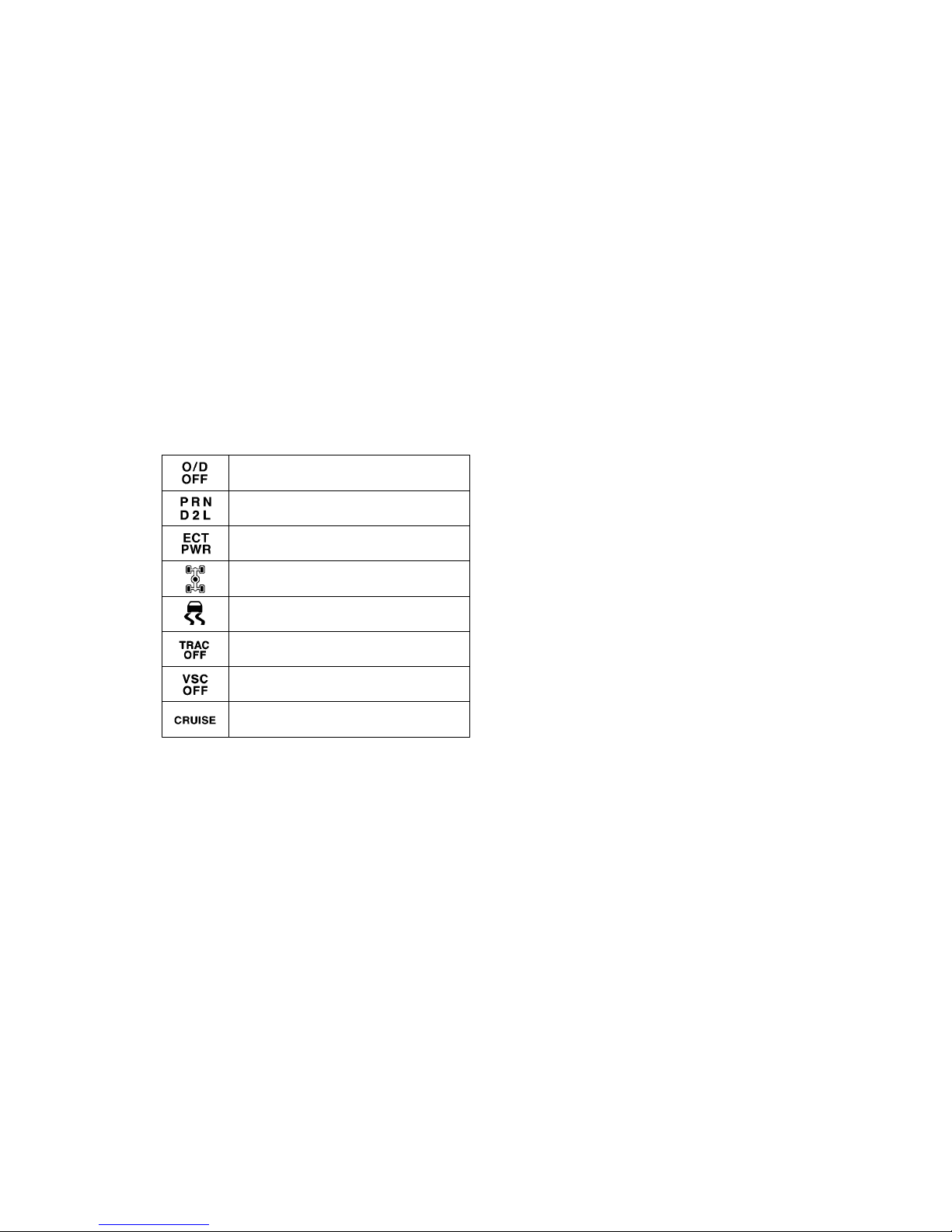
Cruise control indicator light
∗
2
Driving pattern (“PWR” mode) indicator light
∗
1
: For details, see “Service reminder indicators and warning
buzzers” in Section 1–5.
∗
2
: If this light flashes, see “Cruise control” in Section 1–6.
Four–wheel driv e and center diff erential lock
indicator l ights
Automatic transmission indicator lights
Traction contr ol system off indicator light
∗
1
(two–wheel driv e models)
Vehicle skid control system off indicator light
∗
1
(four–wheel drive models)
Slip indicator light
Overdrive–off indicator light
Page 14

’02 4Runner_U (L/O 0108)
8
2002 MY 4RUNNER_U (OM35787U)
Page 15
’02 4Runner_U (L/O 0108)
9
2002 MY 4RUNNER_U (OM35787U)
OPERATION O F INSTRUMENTS AND
CONTROLS
Keys and Doors
Keys 10. . . . . . . . . . . . . . . . . . . . . . . . . . . . . . . . . . . . . . . . . . . . . . . . . . . . . . .
Engine immobiliser system 13. . . . . . . . . . . . . . . . . . . . . . . . . . . . . . . . . . .
Side doors 14. . . . . . . . . . . . . . . . . . . . . . . . . . . . . . . . . . . . . . . . . . . . . . . . . .
Power windows 22. . . . . . . . . . . . . . . . . . . . . . . . . . . . . . . . . . . . . . . . . . . . . .
Power back window 24. . . . . . . . . . . . . . . . . . . . . . . . . . . . . . . . . . . . . . . . . .
Back door 26. . . . . . . . . . . . . . . . . . . . . . . . . . . . . . . . . . . . . . . . . . . . . . . . . . .
Hood 28. . . . . . . . . . . . . . . . . . . . . . . . . . . . . . . . . . . . . . . . . . . . . . . . . . . . . . .
Theft deterrent system 29. . . . . . . . . . . . . . . . . . . . . . . . . . . . . . . . . . . . . . .
Fuel tank cap 31. . . . . . . . . . . . . . . . . . . . . . . . . . . . . . . . . . . . . . . . . . . . . . .
Electric moon roof 32. . . . . . . . . . . . . . . . . . . . . . . . . . . . . . . . . . . . . . . . . . .
SECTION 1–
2
Page 16
’02 4Runner_U (L/O 0108)
10
2002 MY 4RUNNER_U (OM35787U)
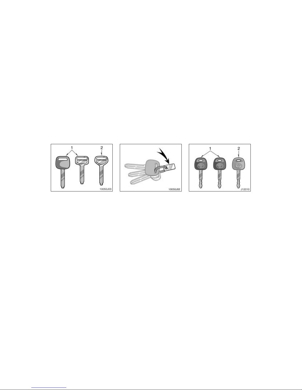
Your vehicle is supplied with two kinds
of keys.
1. Master key—This key works in every
lock.
2. Sub key—This key will not work in the
glove box.
To protect things locked in the glove box
when you have your vehicle parked, leave
the sub key with the attendant.
Since the doors can be locked without a
key, you should always carry a spare
master key in case you accidentally lock
your keys inside the vehicle.
KEY NUMBER PLATE
Your key number is shown on the plate.
Keep the plate in a safe place such as
your wallet, not in the vehicle.
If you should lose your keys or if you
need additional keys, duplicates can be
made by a Toyota dealer using the key
number.
We recommend you to write down the key
number and keep it in safe place.
Your vehicle is supplied with the two
kinds of keys.
1. Master key (black)—This key works in
every lock. Your Toyota dealer will
need it to make you a new key with
built–in transponder chip.
2. Sub key (gray)—This key does not
work in the glove box.
A transponder chip for engine immobiliser
system has been filled in the head of the
master and sub keys. These chips are
needed to enable the system to function
correctly, so be careful not to lose these
keys. If you make your own duplicate key,
you will not be able to cancel the system
or start the engine.
Keys (without engine
immobiliser system)
Keys (with engine immobiliser
system)
Page 17
’02 4Runner_U (L/O 0108)
11
2002 MY 4RUNNER_U (OM35787U)
To protect things locked in the glove box
when you have your vehicle parked, leave
the sub key with the attendant.
Since the side doors can be locked without a key, you should always carry a
spare master key in case you accidentally
lock your keys inside the vehicle.
For information on use of the wireless
remote control key, see “Side doors” in
this section.
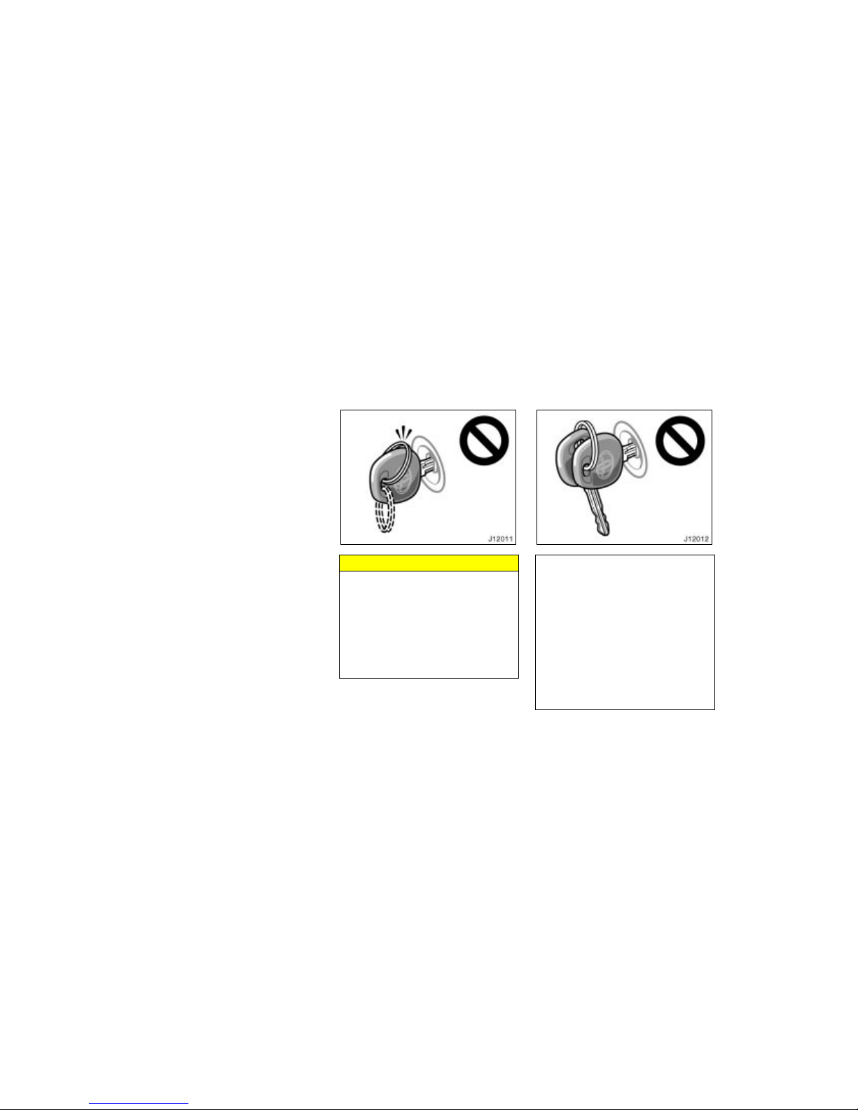
NOTICE
When using a key containing a transponder chip, observe the following
precautions:
When starting the engine, do not
use the key with a key ring resting
on the key grip and do not press
the key ring against the key grip.
Otherwise the engine may not start,
or may stop soon after it starts.
When starting the engine, do not
use the key with other transponder
keys around (including keys of other vehicles) and do not press other
key plates against the key grip.
Otherwise the engine may not start,
or may stop soon after it starts. If
this happens, remove the key once
and then insert it again after taking
off other transponder keys (including keys of other vehicles) from the
ring or while gripping or covering
them with your hand to start the
engine.
Page 18
’02 4Runner_U (L/O 0108)
12
2002 MY 4RUNNER_U (OM35787U)
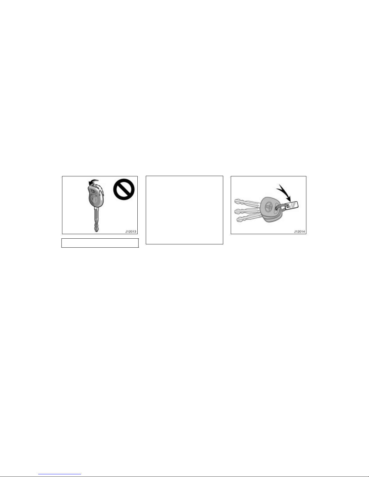
Do not bend the key grip.
Do not cover the key grip with any
material that cuts off electromagnetic waves.
Do not knock the key hard against
other objects.
Do not leave the key exposed to
high temperatures for a long period,
such as on the dashboard and hood
under the direct sunlight.
Do not put the key in water or
wash it in an ultrasonic washer.
Do not use the key with electromagnetic materials.
KEY NUMBER PLATE
Your key number is shown on the plate.
Keep the plate in a safe place such as
your wallet, not in the vehicle.
If you should lose your keys or if you
need additional keys, duplicates can be
made by a Toyota dealer using the key
number.
We recommend you to write down the key
number and keep it in safe place.
Page 19
’02 4Runner_U (L/O 0108)
13
2002 MY 4RUNNER_U (OM35787U)
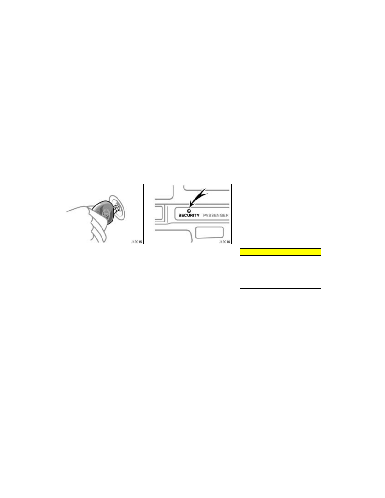
The engine immobiliser system is a
theft prevention system. When you insert the key in the ignition switch, the
transponder chip in the key’s head
transmits an electronic code to the vehicle. The engine will start, only when
the electronic code in the chip corresponds to the registered ID code for
the vehicle.
The system is automatically set when the
key is removed from the ignition switch.
The indicator light will start flashing to
show the system is set.
If any of the following indicator conditions
occurs, contact your Toyota dealer.
The indicator light stays on except
when the theft deterrent system is setting or activating. (See “Theft deterrent
system”.)
The indicator light does not start flash-
ing when the key is removed from the
ignition switch.
The indicator light flashes unsteady.
Inserting the registered key in the ignition
switch automatically cancels the system,
which enables the engine to start. The
indicator light will go off.
For your Toyota dealer to make you a
new key with built–in transponder chip,
your dealer will need your key number
and master key. However, there is a limit
to the number of additional keys your
Toyota dealer can make for you.
If you make your own duplicate key,
you will not be able to cancel the system or start the engine.
NOTICE
Do not modify, remove or disassemble the engine immobiliser system. If any unauthorized changes or
modifications are made, the proper
operation of the system cannot be
guaranteed.
Engine immobiliser system
Page 20
’02 4Runner_U (L/O 0108)
14
2002 MY 4RUNNER_U (OM35787U)
For vehicles sold in U.S.A.
FCC ID: MOZ RI–4BTY
MADE IN JAPAN
This device complies with Part 15 of the
FCC Rules. Operation is subject to the
following two conditions:
(1) This device may not cause harmful
interference, and (2) this device must
accept any interference received, including interference that may cause undesired operation.
CAUTION
Changes or modifications not expressly approved by the par ty responsible for compliance could void the
user’s authority to operate the equipment.
For vehicles sold in Canada
This device complies with RSS–210 of
Industry Canada. Operation is subject to
the following two conditions:
(1) This device may not cause interference, and (2) this device must accept
any interference, including interference
that may cause undesired operation of
the device.
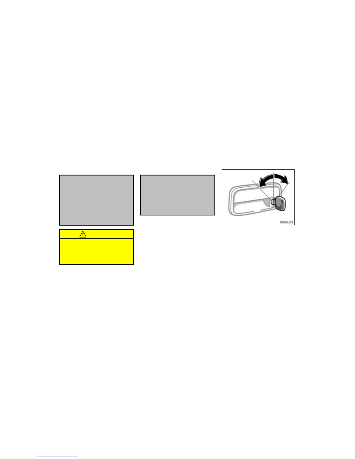
LOCKING AND UNLOCKING WITH KEY
Insert the key into the keyhole and turn
it.
To lock: Turn the key forward.
To unlock: Turn the key backward.
Vehicles with power door lock system—
All the doors lock and unlock simultaneously with either front door. In the driver’s door lock, turning the key once will
unlock the driver’s door and twice in succession will unlock all the doors simultaneously.
Side doors
Page 21
’02 4Runner_U (L/O 0108)
15
2002 MY 4RUNNER_U (OM35787U)
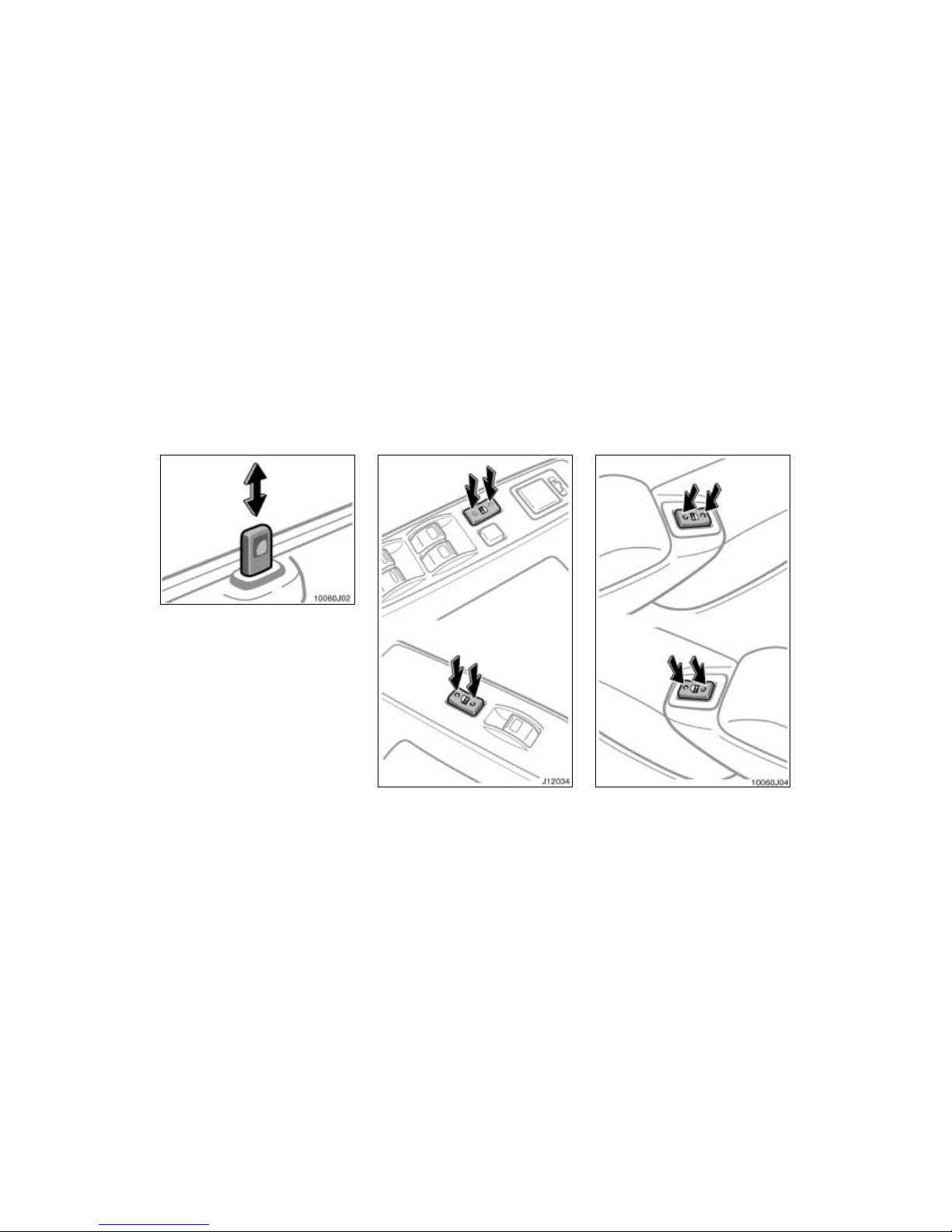
LOCKING AND UNLOCKING WITH
INSIDE LOCK BUTTON
Move the lock button.
To lock: Push the button downward.
To unlock: Pull the button upward.
Closing the door with the lock button
pushed in will also lock the door. Be careful not to lock your keys in the vehicle.
Vehicles with power door lock system—The front doors cannot be locked if
you leave the key in the ignition switch.
Driver’s side
Front passenger’s s ide
With power windows
Front passenger’s side
Driver’s side
Without power windows
Page 22
’02 4Runner_U (L/O 0108)
16
2002 MY 4RUNNER_U (OM35787U)
LOCKING AND UNLOCKING WITH
POWER DOOR LOCK SWITCH
Push the switch.
To lock: Push the switch on the front side.
To unlock: Push the switch on the rear
side.
All the doors lock or unlock simultaneously.
When the front side doors are locked from
the outside or locked with the wireless
remote control transmitter, the power door
lock switch will not work until either front
door is unlocked with the key, lock knob,
or wireless remote control transmitter.
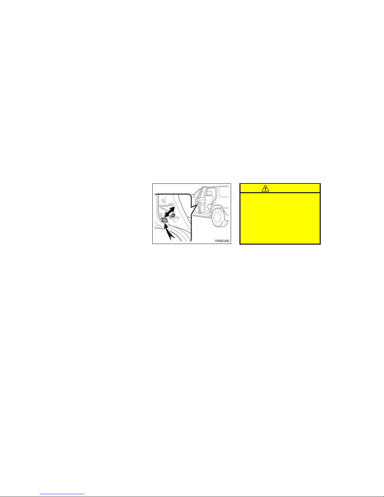
REAR DOOR CHILD–PROTECTORS
Move the lock lever to the “LOCK”
position as shown on the label.
This feature allows you to lock a rear
door so it can be opened from the outside
only, not from inside. We recommend using this feature whenever small children
are in the vehicle.
CAUTION
Before driving, be sure that the doors
are closed and locked, especially
when small children are in the vehicle. Along with the proper use of
seat belts, locking the doors helps
prevent the driver and passengers
from being thrown out from the vehicle during an accident. It also helps
prevent the doors from being opened
unintentionally.
Page 23
’02 4Runner_U (L/O 0108)
17
2002 MY 4RUNNER_U (OM35787U)
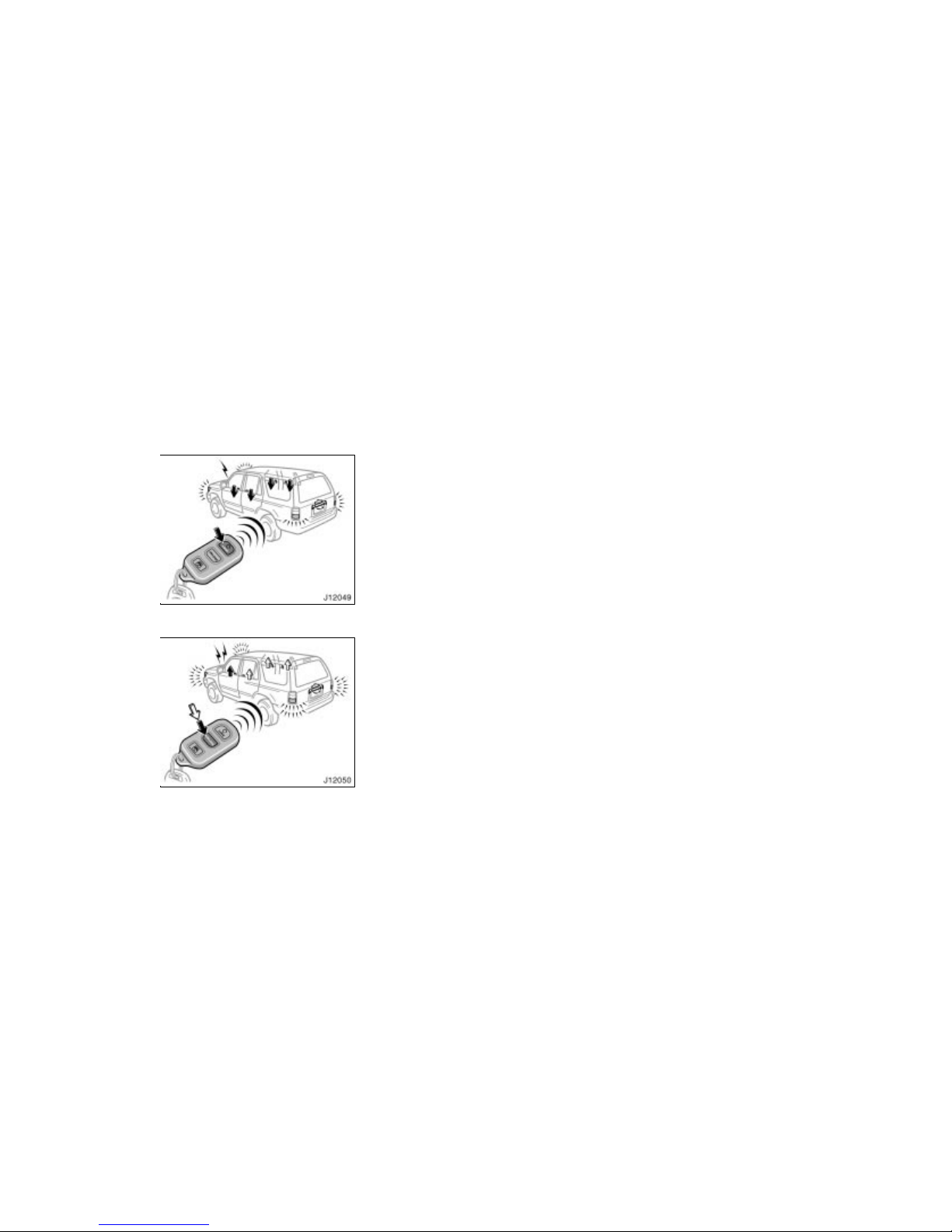
Locking operation
Unlocking operation
The wireless remote control system is
designed to lock or unlock all the side
doors and back door from a distance
within approximately 1 m (3 ft.) of the
vehicle.
LOCKING AND UNLOCKING THE SIDE
DOORS AND BACK DOOR
To lock and unlock all the side doors
and back door, push the swi tches slowly and securely.
To lock: Push the “LOCK” switch. All the
side doors and back door are locked simultaneously. At this time one beep will
be heard, and tail lights flash once.
Check to see that all the side doors and
back door are securely locked.
If any of the side doors or back door is
not securely closed, locking cannot be
performed by the “LOCK” switch and a
beep will sound continuously for 10 seconds. However, if the key is in the ignition, a beep will not sound.
To stop the buzzer, close all the doors
securely or push the “UNLOCK” switch.
To unlock: Push the “UNLOCK” switch
once to unlock the driver’s door alone.
Pushing the switch twice within 3 seconds
unlocks all the side doors and back door
simultaneously. Each time the “UNLOCK”
switch is pushed, two beeps will be heard,
and the parking lights and tail lights flash
twice.
You have 30 s econds to open a door a fter
using the wireless remote unlock feature.
If a door is not opened by then, all the
side doors and back door will be automatically locked again.
If the “LOCK” or “UNLOCK” switch is kept
pressed in, the locking or unlocking operation is not repeated. Release the button
and then push again.
The volume of beep sound can be
changed. Contact your Toyota dealer for
details if you require it.
—Wireless remote control
Page 24
’02 4Runner_U (L/O 0108)
18
2002 MY 4RUNNER_U (OM35787U)
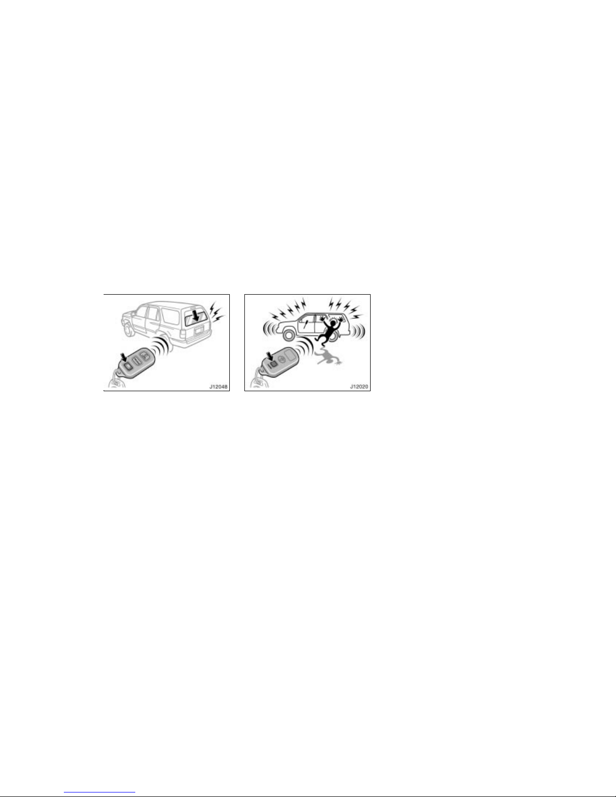
OPENING THE BACK WINDOW
To open the back window, push the
back window open switch of the transmitter for about 1 second. The window
will fully open.
At this time, you can hear a beep.
If the ignition switch is in the “ON” posi-
tion, the back window cannot be opened
by the back window open switch.
To open the back window with the master
key, see “Power back window” in this section.
The volume of beep sound can be
changed. Contact your Toyota dealer for
details if you require it.
“PANIC” SWITCH
Pushing the “PANIC” switch blows the
horn intermittently and flashes the
headlights and tail lights.
The “PANIC” switch is used to deter vehicle theft when you witness anyone attempting to break into or damage your
vehicle.
The alarm will last for one minute. To stop
alarm midway, push the “PANIC” or
“UNLOCK” switch, or unlock any side door
or back door with key. You can also stop
the alarm by turning the ignition key from
“LOCK” to the “ON” position.
The “PANIC” mode does not work when
the ignition key is in the “ON” position.
WIRELESS REMOTE CONTROL
TRANSMITTER
The wireless remote control transmitter is
an electronic component. Observe the following instructions in order not to cause
damage to the transmitter.
Do not leave the transmitter on places
where the temperature becomes high
such as on the dashboard.
Do not disassemble it.
Avoid knocking it hard against other
objects or dropping it.
Avoid putting it in water.
You can use up to 4 wireless remote control transmitters for the same vehicle.
Contact your Toyota dealer for detailed
information.
Page 25
’02 4Runner_U (L/O 0108)
19
2002 MY 4RUNNER_U (OM35787U)
If the wireless remote control transmitter
does not actuate the doors or operate
from a normal distance:
Check for closeness to a radio trans-
mitter such as a radio station or an
airport which can interfere with normal
operation of the transmitter.
The battery may have been consumed.
Check the battery in the transmitter. To
replace the battery, see following
“REPLACING THE BATTERY”.
If you lose your wireless remote control
transmitter, contact your Toyota dealer as
soon as possible to avoid the possibility
of theft, or an accident.
For vehicles sold in U.S.A.
This device complies with Part 15 of the
FCC Rules. Operation is subject to the
following two conditions:
(1) This device may not cause harmful
interference, and (2) this device must
accept any interference received, including interference that may cause undesired operation.
NOTICE:
This equipment has been tested and
found to comply with the limits for a
Class B digital device, pursuant to Part
15 of the FCC Rules. These limits are
designed to provide reasonable protection against harmful interference in a
residential installation. This equipment
generates, uses and can radiate radio
frequency energy and, if not installed
and used in accordanc e with the instructions, may cause harmful interference to
radio communications. However, there is
no guarantee that interference will not
occur in a particular installation. If this
equipment does cause harmful interference to radio or television reception,
which can be determined by turning the
equipment off and on, the user is encouraged to try to correct the interference by one or more of the following
measures:
Page 26
’02 4Runner_U (L/O 0108)
20
2002 MY 4RUNNER_U (OM35787U)
Reorient or relocate the receiving an-
tenna.
Increase the separation between the
equipment and receiver.
Connect the equipment into an outlet
on a circuit different from that to
which the receiver is connected.
Consult the dealer or an experienced
radio / TV technician for help.
FCC WARNING:
Changes or modifications not expressly approved by the par ty responsible for compliance could void the
user’s authority to operate the equipment.
For vehicles sold in Canada
Operation is subject to the following two
conditions:
(1) this device may not cause interference, and (2) this device must accept
any interference, including interference
that may cause undesired operation of
the device.
REPLACING THE BATTERY
For replacement, use a lithium battery
CR2016 and a special screwdriver.
CAUTION
Special care should be taken that
small children do not swallow the removed battery or components.
NOTICE
When replacing the transmitter battery, be careful not to lose the components.
Replace only with the same or
equivalent type recommended by
the manufacturer.
Dispose of used batteries according
to the local laws.
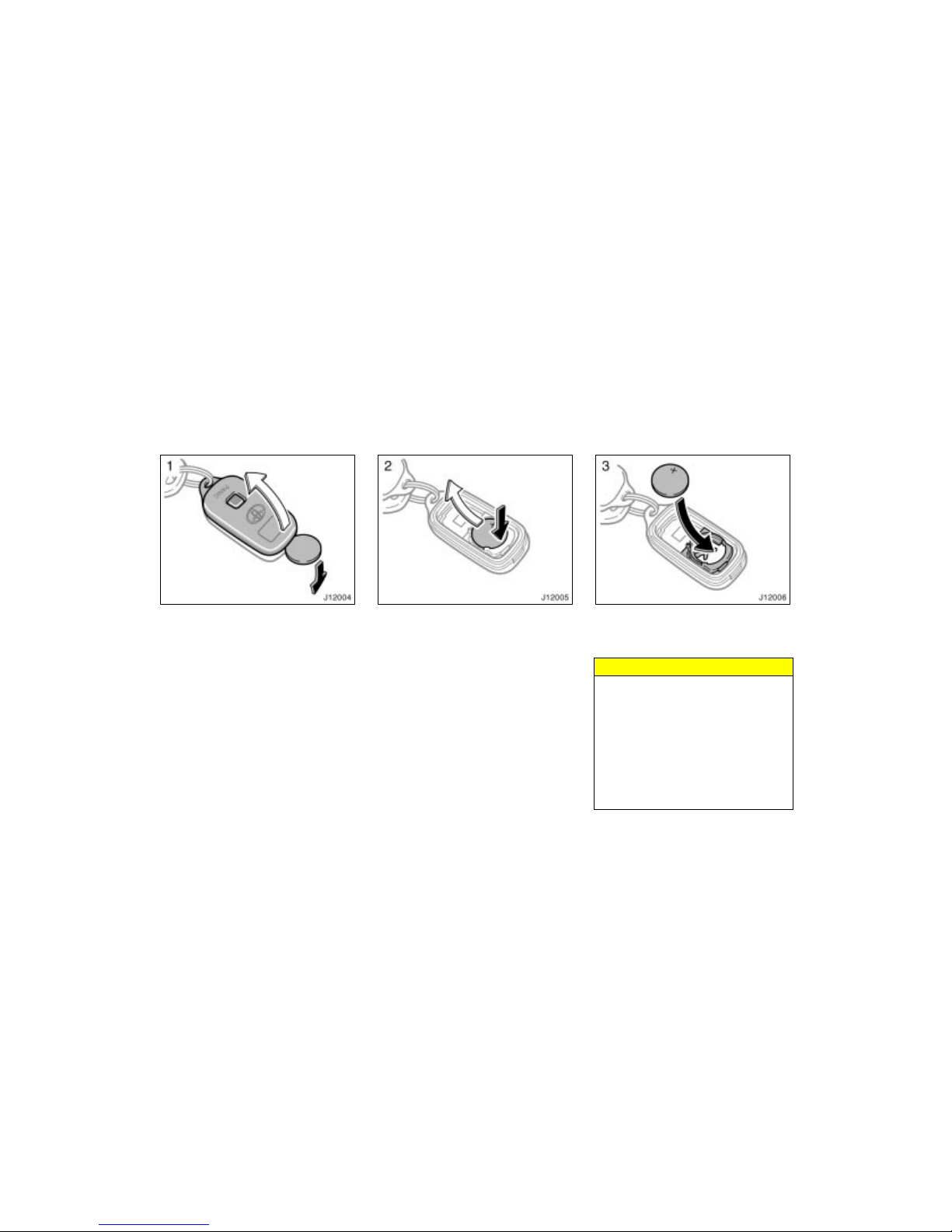
Replace the battery by the following procedures:
Page 27
’02 4Runner_U (L/O 0108)
21
2002 MY 4RUNNER_U (OM35787U)
1. Using a coin or equivalent, open the
transmitter case.
2. Remove the discharged transmitter battery.
3. Put new transmitter battery with positive (+) side up.
Close the transmitter case securely.
NOTICE
Make sure the positive side and
negative side of the transmitter battery should be faced correctly.
Do not replace the battery with wet
hands. Water may cause unexpected
rust.
Do not touch or move any components inside of the transmitter, or
it may interfere with proper operation.
Page 28
’02 4Runner_U (L/O 0108)
22
2002 MY 4RUNNER_U (OM35787U)
Be careful that dust or oils do not
adhere to the transmitter case.
Close the transmitter case securely.
After replacing battery, check that the
transmitter operates properly. If the transmitter still does not operate properly, contact your Toyota dealer.
If you lose your transmitter, contact your
Toyota dealer as soon as possible to
avoid the possibility of theft, or an accident. (See “If you lose your wireless remote control transmitter” in Section 4.)
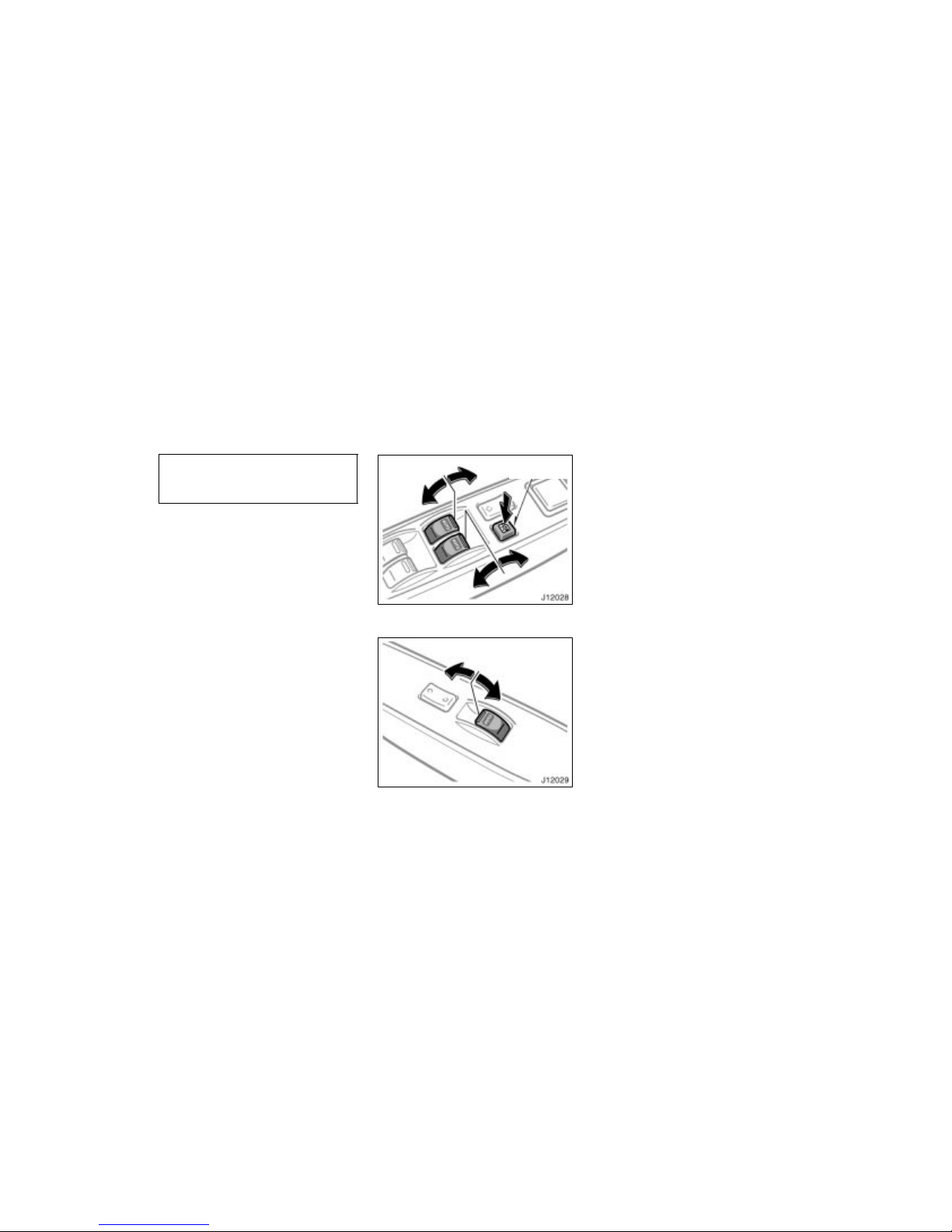
Window lock
switch
Driver’s door switches
Front passenger’s door switch
The windows can be operated with the
switch on each side door.
The power windows work when the igniti on
switch is in the “ON” position.
Key off operation: If both front side
doors are closed, they work for 43 seconds even after the ignition switch is
turned off. They stop working when either
front side door is opened.
OPERATING THE DRIVER’S AND FRONT
PASSENGER’S WINDOWS
Use the switches on the driver’s door
and front passenger’s door.
Normal operation: The window moves as
long as you hold the switch.
To open: Lightly push down the switch.
To close: Lightly pull up the switch.
If you push in the window lock switch on
the driver’s door, the front passengers’
window cannot be operated.
Power windows
Page 29
’02 4Runner_U (L/O 0108)
23
2002 MY 4RUNNER_U (OM35787U)
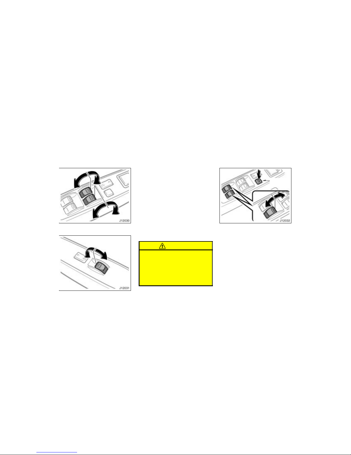
Driver’s door switches
Front passenger’s door switch
Automatic operation: Push the switch
completely down or pull it completely up,
and then release it. The window will fully
open or close. To stop the window partway, lightly move the switch in the opposite direction and then release it.
If you push in the window lock switch on
the driver’s door, the front passengers’
window cannot be operated.
Jam protection function: During aut omatic closing operation, the window stops and
opens half way if something gets caught
between the window and window frame.
If the window receives a strong impact,
this function may work even if nothing is
caught.
CAUTION
Never try jamming any part of your
body to make the jam protection
function work intentionally.
The jam protection function may
not work if something gets caught
just before the window is fully
closed.
Window
lock switch
Driver’s door switches
OPERATING THE REAR PASSENGERS’
WINDOWS
Use the switch on each rear passenger’s door or the switches on the driver’s door that control each rear passenger’s windows.
The window moves as long as you hold
the switch.
To open: Push down the switch.
To close: Pull up the switch.
If you push in the window lock switch on
the driver’s door, the rear passengers’
windows cannot be operated.
Page 30
’02 4Runner_U (L/O 0108)
24
2002 MY 4RUNNER_U (OM35787U)
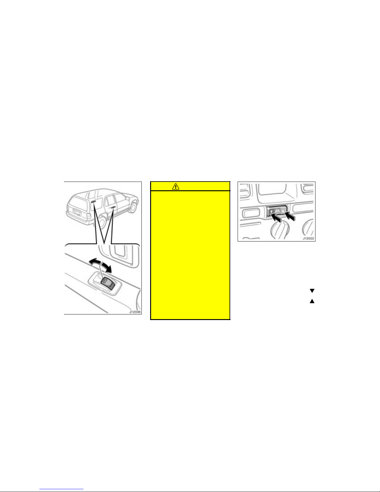
Rear passengers’ door switches
CAUTION
To avoid serious personal injury, you
must do the following.
Always make sure the heads, hands
and other parts of the bodies of all
occupants are kept completely inside the vehicle before you close
the power windows. If someone’s
neck, head or hands gets caught in
a closing window, it could result in
a serious injury. When anyone
closes the power windows, make
sure that he/she operates the windows safely.
When small children are in the ve-
hicle, never let them use the power
window switches without supervision. Use the window lock switch to
prevent them from making unexpected use of the switches.
Never leave small children alone in
the vehicle, especially with the ignition key still inserted. They could
use the power window switches and
get trapped in a window. Unattended children can be involved in
serious accidents.
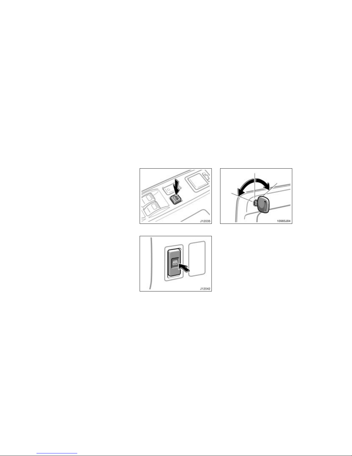
The back window can be operated with
the inner switch on the center console
or outer switch on the back door.
OPERATING FROM INSIDE
The ignition key must be in the “ON” position.
The back window moves as long as you
hold the inner switch.
To open: Push the switch on the “
”
side.
To close: Push the switch on the “
”
side.
Power back window
Page 31
’02 4Runner_U (L/O 0108)
25
2002 MY 4RUNNER_U (OM35787U)
You can also open t he back window when
the back window wiper is working. At that
time, the wiper stops working until the
window is closed again.
If you push in the window lock switch on
the driver’s door (with power windows) or
on the instrument panel (without power
windows), the back window cannot be operated.
With power windows (driver’s door)
Without power windows
(instrument panel)
OPERATING FROM OUTSIDE
After turning and holding the key for a few
seconds, the back window will move as
far as holding the key.
To open: Turn the key counterclockwise.
To close: Turn the key clockwise.
You can also open t he back window when
the back window wiper is working. At the
time, the wiper stops working until the
window is closed again.
Page 32
’02 4Runner_U (L/O 0108)
26
2002 MY 4RUNNER_U (OM35787U)
CAUTION
To avoid serious personal injury, you
must do the following.
Always make sure the heads, hands
and other parts of the bodies of all
occupants are kept completely inside the vehicle before you close
the power back window. If someone’s neck, head or hands gets
caught in a closing window, it
could result in a serious injury.
When anyone closes the power
back window, make sure that he/she
operates the window safely.
When small children are in the ve-
hicle, never let them use the power
back window switch without supervision. Use the window lock switch
to prevent them from making unexpected use of the switch.
Never leave small children alone in
the vehicle, especially with the ignition key still inserted. They could
use the power back window switch
and get trapped in a window. Unattended children can be involved in
serious accidents.
Keep the back window closed while
driving. This not only keeps the
luggage from being thrown out but
also prevents exhaust gases from
entering the vehicle.
Vehicles with wireless remote control system—To open the back window with the
wireless remote control transmitter, see
“—Wireless remote control” in this section.
LOCKING AND UNLOCKING WITH KEY
Insert the key into the keyhole and turn
it.
To lock: Turn the key clockwise.
To unlock: Turn the key counterclockwise.
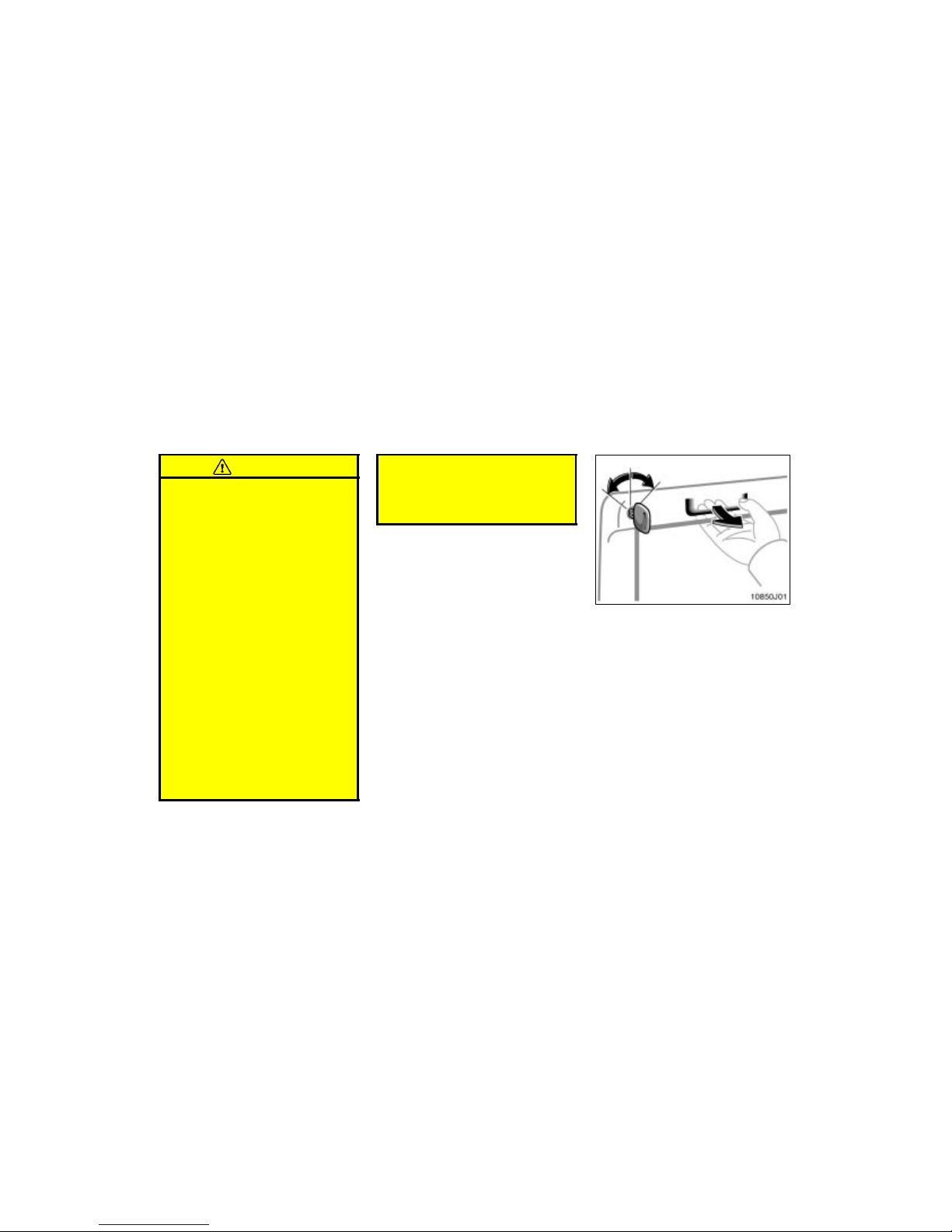
To open the back door, pull the lever.
The back door will be controlled by oper-
ating the power door lock switch.
Back door
Page 33
’02 4Runner_U (L/O 0108)
27
2002 MY 4RUNNER_U (OM35787U)
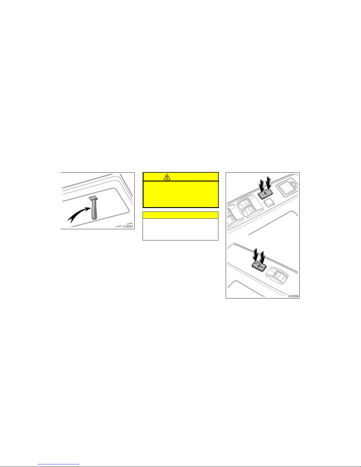
When closing the back door, use the
inside strap for easier reach to the
back door.
To close the back door, lower it and press
down on it. After closing the back door,
try pulling it up to make sure it is securely closed.
See “Luggage stowage precautions” in
Section 2 for precautions in loading luggage.
CAUTION
Keep the back window and back door
closed while driving. This not only
keeps the luggage from being thrown
out but also prevents exhaust gases
from entering the vehicle.
NOTICE
To prevent damage to the back door
dampers, do not apply any force,
paint or let any other foreign matter
on them.
Driver’s side
Front passenger’s s ide
With power windows
Page 34
’02 4Runner_U (L/O 0108)
28
2002 MY 4RUNNER_U (OM35787U)
Front passenger’s side
Driver’s side
Without power windows
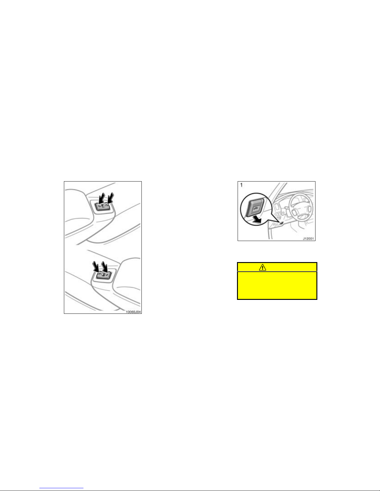
LOCKING AND UNLOCKING WITH
POWER BACK DOOR LOCK SWITCH
Push the switch.
To lock: Push the switch on the front side.
To unlock: Push the switch on the rear
side.
Operating the power door lock switch simultaneously locks or unlocks the back
door. (See “Side doors” in this section.)
Vehicles with wireless remote control system—To lock or unlock the back door, see
“—Wireless remote control” in this section.
To open the hood:
1. Pull the hood lock release lever. The
hood will spring up slightly.
CAUTION
Before driving, be sure that the hood
is closed and securely locked. Otherwise, the hood may open unexpectedly while driving and an accident may
occur.
Hood
Page 35
’02 4Runner_U (L/O 0108)
29
2002 MY 4RUNNER_U (OM35787U)
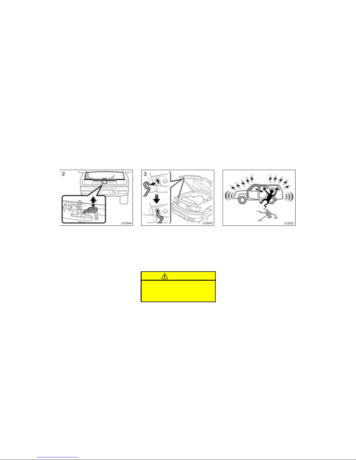
2. In front of the vehicle, pull up the
auxiliary catch lever and lift the
hood.
3. Hold the hood open by inserting the
support rod into the slot.
Before closing the hood, check to see that
you have not forgotten any tools, rags,
etc. and return the support rod to its
clip—this prevents rattles. Then lower the
hood make sure it locks into place. If
necessary, press down gently on the front
edge to lock it.
CAUTION
After inserting the support rod into
the slot, make sure the rod supports
the hood security from falling down
on to your head or body.
To deter the vehicle theft, the system
is designed to give an alarm if any of
the side doors, back door or hood is
forcibly unlocked or opened or the battery terminal is disconnected and then
reconnected when the vehicle is locked.
The alarm blows the horn intermittently
and flashes the headlights and tail lights.
Theft deterrent system
Page 36
’02 4Runner_U (L/O 0108)
30
2002 MY 4RUNNER_U (OM35787U)
SETTING THE SYSTEM
1. Turn the ignition key to the “LOCK”
position and remove it.
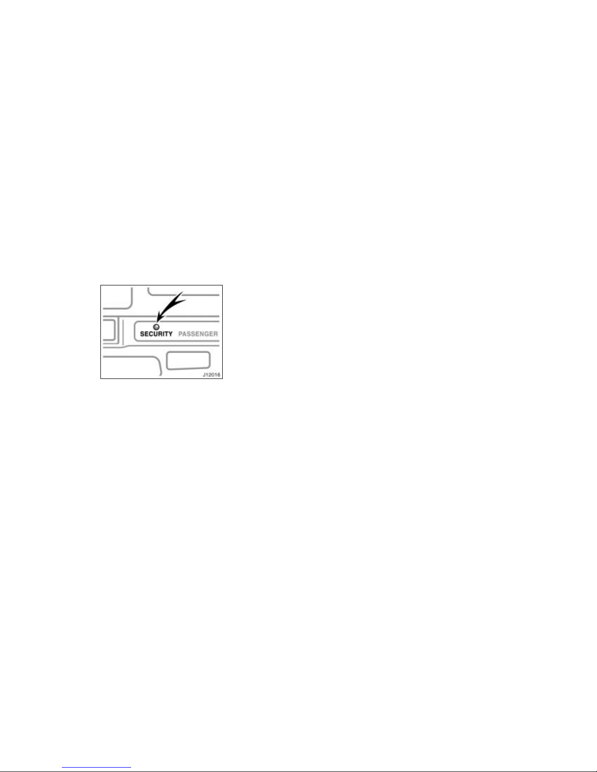
The indicator light will start flashing when
the key is removed from the ignition
switch. (See “Engine immobiliser system”
for details.)
2. Have all passengers get out of the
vehicle.
3. Close and lock all the side doors, back
door and hood.
The indicator light will come on when all
the side doors, back door and hood are
closed and locked.
The system will automatically be set after
30 seconds. When the system is set, the
indicator light will start flashing again.
4. After making sure the indicator light
starts flashing, you may leave the vehicle.
Never leave anyone in the vehicle when
you set the system, because unlocking
from the inside will activate the system.
WHEN THE SYSTEM IS SET
Activating the system
The system will give the alarm under the
following conditions:
If any of the side doors is unlocked or
opened without the key or wireless remote control transmitter, or if the back
door or hood is forcibly opened.
If the battery terminal is disconnected
and then reconnected.
The indicator light will come on when the
system is activated.
If the alarm has been activated and the
key is not in the ignition switch, all the
side doors and back door will re–lock automatically.
After one minute, the alarm will automatically stop and the indicator light will starts
flashing again.
Reactivating the alarm
Once set, the system automatically resets
the alarm after the alarm stops.
The alarm will activate again under the
same circumstances described in
“Activating the system”.
Stopping the alarm
The alarm will b e stopped by the following
three ways:
Turn the ignition key from the “LOCK”
to “ON” position.
Unlock any of the side doors or back
door with the key or wireless remote
control transmitter.
These ways cancel the system at the
same time.
Page 37
’02 4Runner_U (L/O 0108)
31
2002 MY 4RUNNER_U (OM35787U)
TESTING THE SYSTEM
1. Open all the windows.
2. Set the system as described above.
The side doors and back door should
be locked with the key or wireless remote control transmitter. Be sure to
wait until the indicator light goes off or
starts flashing.
3. Unlock any side door from the inside.
The system should activate the alarm.
4. Stopping the al arm as described a bove.
5. Repeat this operation for the other
doors and hood. When testing on the
hood, also check that the system is
activated when the battery terminal is
disconnected and then reconnected.
If the system does not work properly,
have it checked by your Toyota dealer.
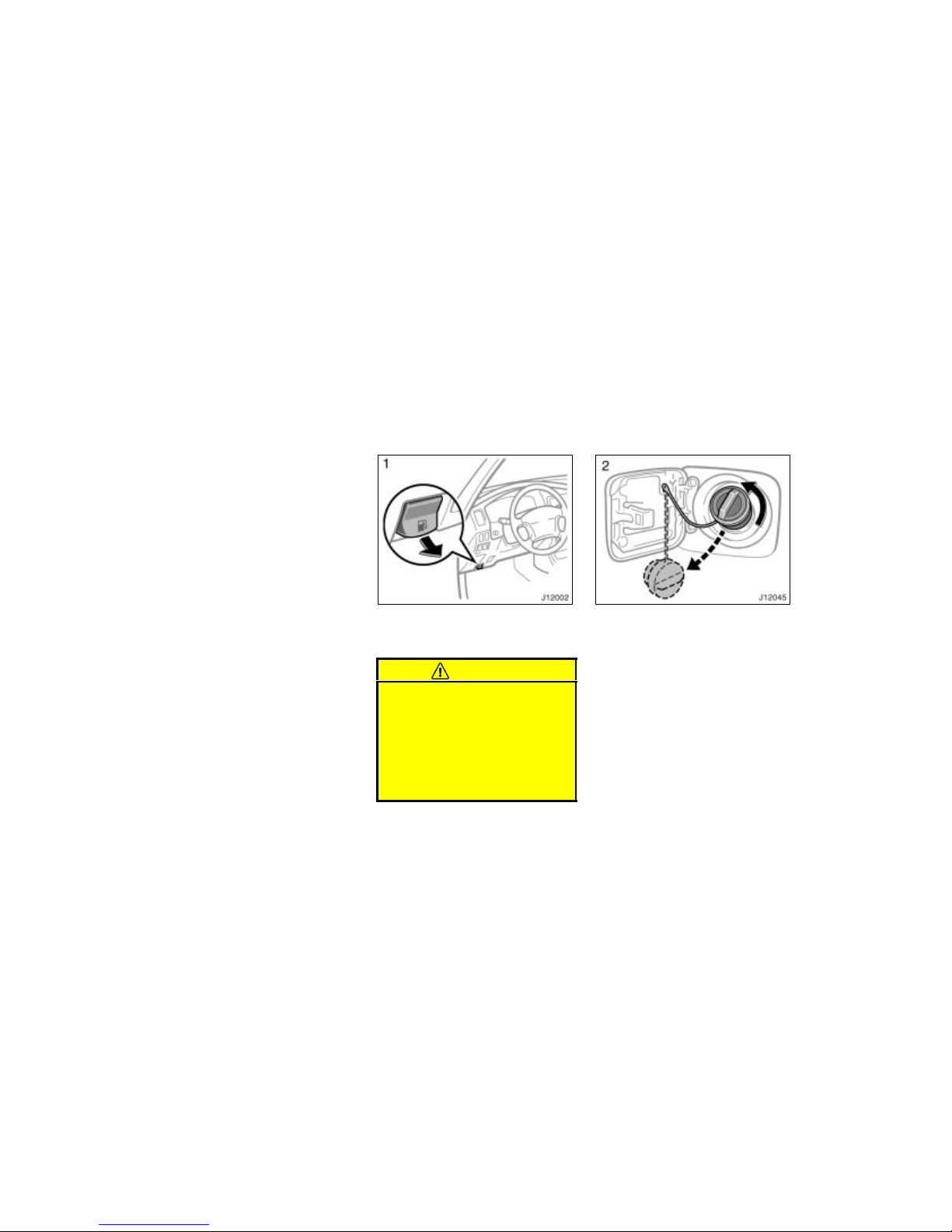
1. To open the fuel filler door, pull the
lever.
When refueling, turn off the engine.
CAUTION
Do not smoke, cause sparks or al-
low open flames when refueling.
The fumes are flammable.
When opening the cap, do not re-
move the cap quickly. In hot weather, fuel under pressure could cause
injury by spraying out of the filler
neck if the cap is suddenly removed.
2. To remove the fuel tank cap, turn
the cap slowly counterclockwise,
then pause slightly before removing
it.
It is not unusual to hear a slight swoosh
when the cap is opened. When installing,
turn the cap clockwise till you hear a
click.
If the cap is not tightened securely, the
malfunction indicator lamp comes on.
Make sure the cap is tightened securely.
The indicator lamp goes off after driving
several times. If the indicator lamp does
not go off, contact your Toyota dealer as
soon as possible.
Fuel tank cap
Page 38
’02 4Runner_U (L/O 0108)
32
2002 MY 4RUNNER_U (OM35787U)
CAUTION
Make sure the cap is tightened se-
curely to prevent fuel spillage in
case of an accident.
Use only a genuine Toyota fuel tank
cap for replacement. It is designed
to regulate fuel tank pressure.
Sliding operation
Tilting operation
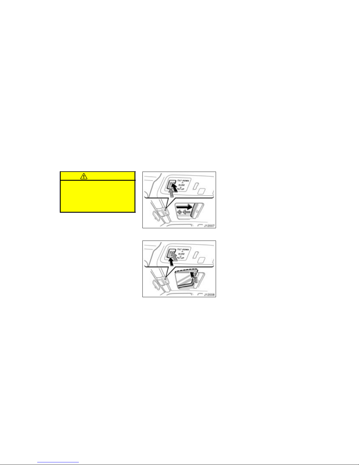
To operate the moon roof, use the
switch beside the personal lights.
The moon roof works when the ignition
switch is in the “ON” position.
Key off operation—
If all the doors are closed, it works for 43
seconds even after the ignition switch is
turned off. It stops working when any of
the doors is opened.
Sun shade operation—
The sun shade can be opened or closed
by hand.
Sliding operation—
To open: Push the swit ch on the “” side.
The roof will fully open. To stop the roof
partway, push the switch on the “” side.
The sun shade will be opened together
with the roof.
To close: Push the switch on the “”
side.
As a precaution when closing, the roof
stops at the three–quarters cl osed position
before fully closing. Therefore, release the
switch and then push it again to close it
completely.
Electric moon roof
Page 39
’02 4Runner_U (L/O 0108)
33
2002 MY 4RUNNER_U (OM35787U)
Tilting operation—
To tilt up: Push the switch on the “TILT
UP” side.
To lower: Push the switch on the “TILT
DOWN” side.
You may stop the moon roof at any desired position. The roof will move while
the switch is being pushed and stop when
released.
CAUTION
To avoid serious personal injury, you
must do the following.
While the vehicle is moving, always
keep the heads, hands and other
parts of the bodies of all occupants
away from the roof opening. Otherwise, they could be seriously injured if the vehicle stops suddenly
or if the vehicle is involved in an
accident.
Always make sure nobody places
his/her head, hands and other parts
of the body in the roof opening before you close the roof. If someone’s neck, head or hands gets
caught in the closing roof, it could
result in a serious injury. When
anyone closes the roof, first make
sure it is safe to do so.
Never leave small children alone in
the vehicle, especially with the ignition key still inserted. They could
use the moon roof switches and get
trapped in the roof opening. Unattended children can be involved in
serious accidents.
Never sit on top of the vehicle
around the roof opening.
Page 40

’02 4Runner_U (L/O 0108)
34
2002 MY 4RUNNER_U (OM35787U)
Page 41
’02 4Runner_U (L/O 0108)
35
2002 MY 4RUNNER_U (OM35787U)
OPERATION O F INSTRUMENTS AND
CONTROLS
Seats, Seat belts, Steering wheel and Mirrors
Seats 36. . . . . . . . . . . . . . . . . . . . . . . . . . . . . . . . . . . . . . . . . . . . . . . . . . . . . .
Front seats 36. . . . . . . . . . . . . . . . . . . . . . . . . . . . . . . . . . . . . . . . . . . . . . . . .
Fold–down rear s eats 39. . . . . . . . . . . . . . . . . . . . . . . . . . . . . . . . . . . . . . . .
Flattening seatbacks 40. . . . . . . . . . . . . . . . . . . . . . . . . . . . . . . . . . . . . . . . .
Seat heaters 41. . . . . . . . . . . . . . . . . . . . . . . . . . . . . . . . . . . . . . . . . . . . . . . .
Head restrai nts 42. . . . . . . . . . . . . . . . . . . . . . . . . . . . . . . . . . . . . . . . . . . . . .
Seat belts 43. . . . . . . . . . . . . . . . . . . . . . . . . . . . . . . . . . . . . . . . . . . . . . . . . . .
SRS driver airbag and front passenger airbag 52. . . . . . . . . . . . . . . . . . .
Child restraint 59. . . . . . . . . . . . . . . . . . . . . . . . . . . . . . . . . . . . . . . . . . . . . . .
Tilt steering wheel 78. . . . . . . . . . . . . . . . . . . . . . . . . . . . . . . . . . . . . . . . . . .
Outside rear view mirrors 79. . . . . . . . . . . . . . . . . . . . . . . . . . . . . . . . . . . . .
Anti–glare i nside rear view mirror 80. . . . . . . . . . . . . . . . . . . . . . . . . . . . . .
Sun visors 81. . . . . . . . . . . . . . . . . . . . . . . . . . . . . . . . . . . . . . . . . . . . . . . . . .
SECTION 1–
3
Page 42
’02 4Runner_U (L/O 0108)
36
2002 MY 4RUNNER_U (OM35787U)
While the vehicle is being driven, all vehicle occupants should have the seatback
upright, sit well back in the seat and properly wear the seat belts provided.
CAUTION
Do not drive the vehicle unless the
occupants are properly seated. Do
not allow sitting on top of a
folded–down seatback, or in the
luggage compartment or cargo area.
Persons not properly seated and/or
properly restrained by seat belts
can be severely injured in the event
of emergency braking or a collision.
During driving, do not allow pas-
sengers to stand up or move
around between seats. Severe injuries can occur in the event of emergency braking or a collision.
Adjust the driver’s seat so that the foot
pedals, steering wheel and instrument
panel controls are within easy reach of
the driver.
CAUTION
Adjustments should not be made
while the vehicle is moving, as the
seat may unexpectedly move and
cause the driver to lose control of
the vehicle.
When adjusting the seat, be careful
that the seat does not hi t a passenger or luggage.
After adjusting the seat position,
try sliding it forward and backward
to make sure it is locked in position.
After adjusting the seatback, push
back your body to make sure it is
locked in position.
Do not put objects under the seats
as they may interfere with the seat–
lock mechanism or unexpectedly
push up the seat position adjusting
lever; the seat may suddenly move,
causing the driver to lose control of
the vehicle.
While adjusting the seat, do not put
your hands under the seat or near
the moving parts. You may catch
and injure your hands or fingers.
Seats
Front seats—
—Seat adjustment precaut ions
Page 43
’02 4Runner_U (L/O 0108)
37
2002 MY 4RUNNER_U (OM35787U)
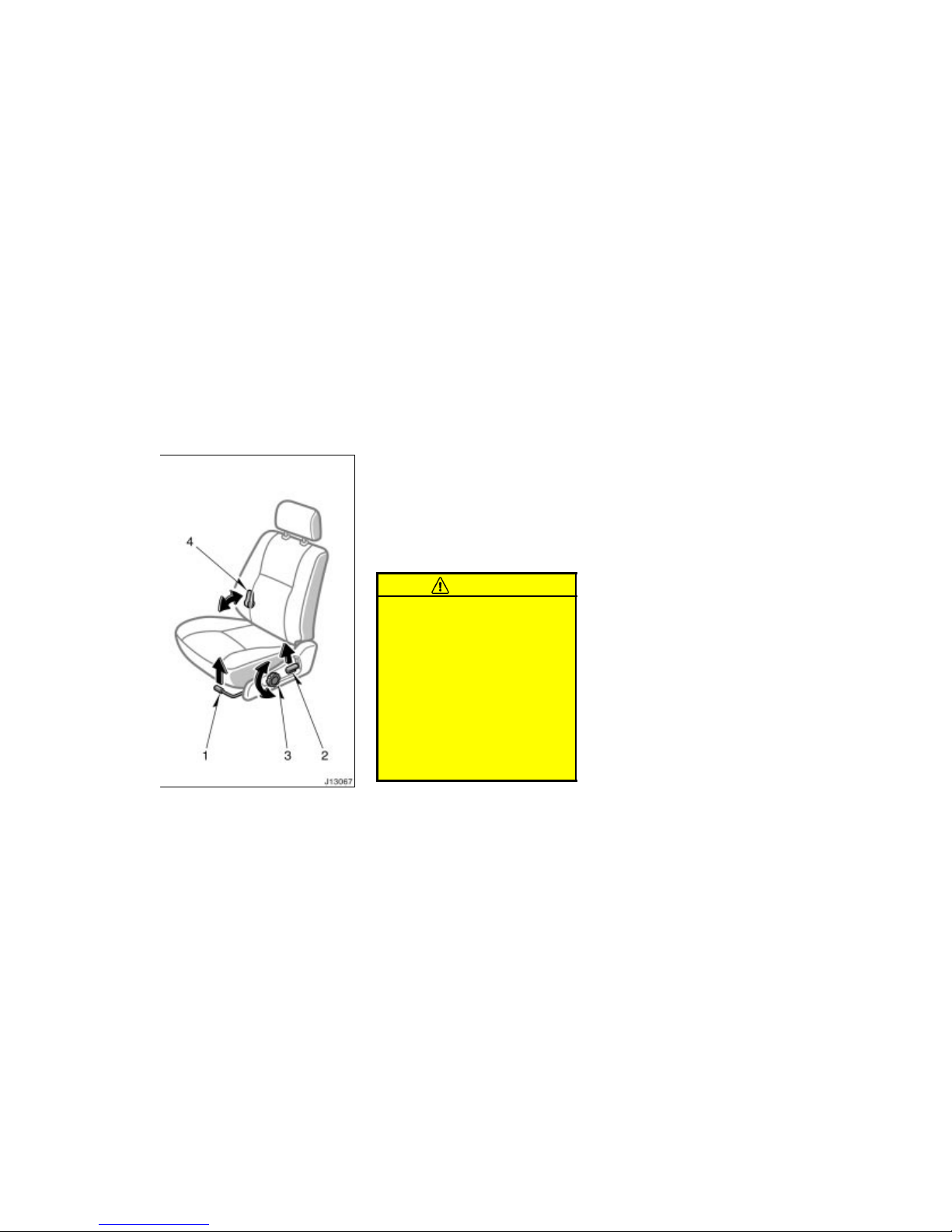
1. SEAT POSITION ADJUSTING LEVER
Pull the lever up. Then slide the seat
to the desired position with slight body
pressure and release the lever.
2. SEATBACK ANGLE ADJUSTING
LEVER
Lean forward and pull the lever up.
Then lean back to the desired angle
and release the lever.
CAUTION
To reduce the risk of sliding under
the lap belt during a collision, avoid
reclining the seatback any more than
needed. The seat belts provide maximum protection in a frontal or rear
collision when the driver and the passenger are sitting up straight and
well back in the seats. If you are
reclined, the lap belt may slide past
your hips and apply restraint forces
directly to the abdomen. Therefore, in
the event of a frontal collision, the
risk of personal injury may increase
with increasing recline of the seatback.
3. SEAT CUSHION ANGLE ADJUSTING
KNOB
Turn the knob either way.
4. SEAT LUMBAR SUPPORT
ADJUSTING LEVER
Pull the lever forward or backward.
—Adjusting front seats
(manual seat)
Page 44
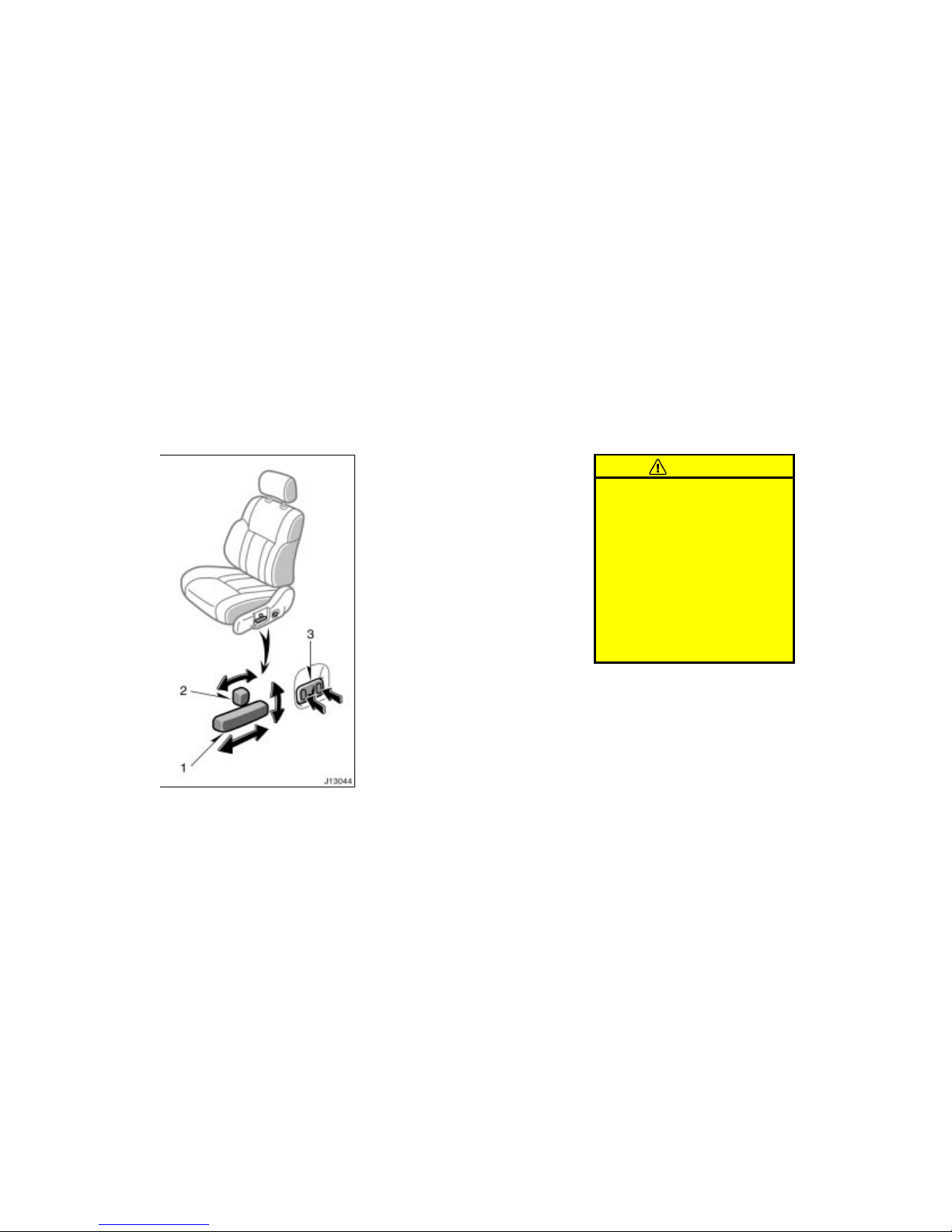
’02 4Runner_U (L/O 0108)
38
2002 MY 4RUNNER_U (OM35787U)
1. SEAT POSITION AND SEAT CUSHION
ANGLE ADJUSTING SWITCH
Move the control switch in the desired
direction.
Releasing the switch will stop the seat at
that position.
Do not place anything under the front
seats. It might interfere with the seat–lock
mechanism.
2. SEATBACK ANGLE ADJUSTING
SWITCH
Move the control switch in the desired
direction.
Releasing the switch will stop the seatback at that position.
CAUTION
To reduce the risk of sliding under
the lap belt during a collision, avoid
reclining the seatback any more than
needed. The seat belts provide maximum protection in a frontal or rear
collision when the driver and the passenger are sitting up straight and
well back in the seats. If you are
reclined, the lap belt may slide past
your hips and apply restraint forces
directly to the abdomen. Therefore, in
the event of a frontal collision, the
risk of personal injury may increase
with increasing recline of the seatback.
3. SEAT LUMBAR SUPPORT
ADJUSTING SWITCH
Push the control switch in the desired
direction.
Releasing the switch will stop the seatback at that position.
—Adjusting front seats (power
seat)
Page 45
’02 4Runner_U (L/O 0108)
39
2002 MY 4RUNNER_U (OM35787U)
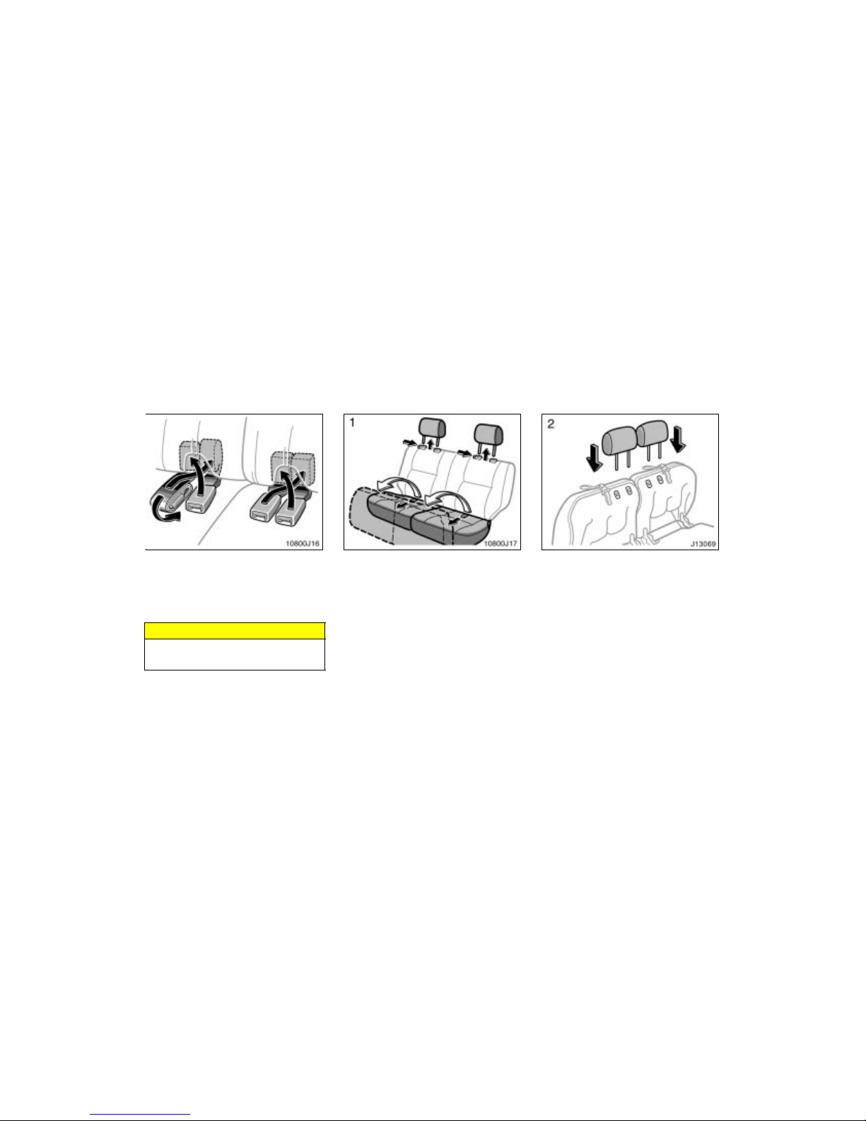
BEFORE FOLD–DOWN REAR SEAT
Stow the rear seat belt and buckles as
shown in the illustration.
This prevents the belt and buckles from
falling out when you fold the seatback.
NOTICE
The seat belt and buckles must be
stowed before you fold the seatback.
1. Swing the bottom cushion up by
pulling the lock release strap, and
remove the head restraint.
It is hinged at the front edge, so just lift
it up.
If desired, each bottom cushion may be
swung up separately.
2. Store the head restraints in the head
restraint retaining holes in the bottom cushion.
Fold–down rear seats
Page 46
’02 4Runner_U (L/O 0108)
40
2002 MY 4RUNNER_U (OM35787U)
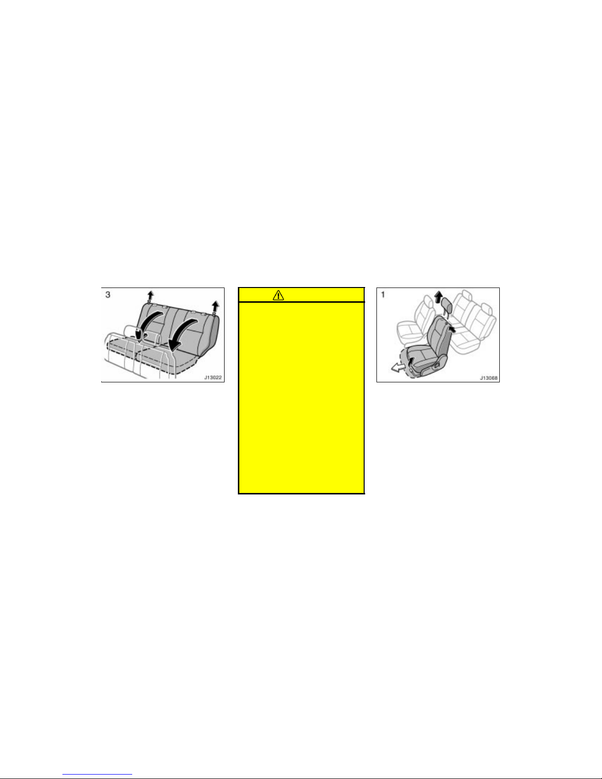
3. Unlock the seatback and fold it
down.
This will enlarge the luggage compartment
as far as the raised seat cushion. See
“Luggage stowage precautions” in Section
2 for precautions in loading luggage.
If desired, each seatback may be folded
separately.
CAUTION
When returning seats to their original
position, observe the following precautions in order to prevent personal
injury in a collision or sudden stop:
Make sure the seatback is securely
locked by pushing for ward and rearward on the top of the seatback.
Failure to do so will prevent the
seat belt from operating properly.
Be certain to replace the head restraints.
Make sure the seat belts are not
twisted or caught in the seatback
and are arranged in their proper
position and are ready to use.
Make sure the bottom cushion is
securely locked by trying to pull up
the edge of the cushion near the
lock release straps.
Do not forget to pull out the buckle
of the side seatbelts and center
seatbelt and arranged them in their
proper position and are ready to
use.
To flatten the seatback, do the followings.
1. Remove the head restraint and slide
the seat further forward than the
front–most lock position.
Flattening seatbacks
(manual seat)
Page 47
’02 4Runner_U (L/O 0108)
41
2002 MY 4RUNNER_U (OM35787U)
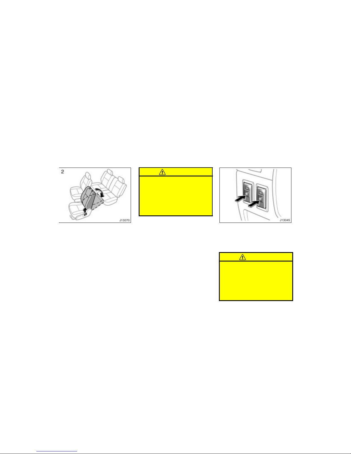
2. Pull the lock release lever up, then
push down the seatback.
When returning the seatback upright, be
careful not to make yourself hit by the
seatback which will bound with considerable spring force.
After returning the seat to its original
position, be certain to replace the head
restraint.
CAUTION
Do not allow passengers to ride on
the flattened seat while driving; use
the seat in the normal position.
After putting back the seat, try
pushing the seat and seatback forward and rearward to make sure it
is secured in place. Be certain to
replace head restraint.
To turn on the seat heater, push the
switch.
The key must be in the “ON” position.
Push the switch once again to turn the
seat heater off.
CAUTION
Occupants must use caution when operating the seat heater because it
may make them feel too hot or cause
burns at low temperatures (erythema,
varicella). Use extra caution for;
Babies, small children, elderly per-
sons, sick persons or handicapped
persons
Seat heaters
Page 48
’02 4Runner_U (L/O 0108)
42
2002 MY 4RUNNER_U (OM35787U)
Persons who have delicate skin
Persons who are exhausted
Persons who have taken alcohol or
drugs which induce sleep (sleeping
drug, cold remedy, etc.)
To prevent the seat overheating, do
not use the seat heater with a blanket, cushion, or other insulating objects which cover the seat.
NOTICE
Do not put unevenly weighed objects on the seat and do not stick
sharp objects (needles, nails, etc.)
into the seat.
When cleaning the seats, do not
use organic substances (paint thinner, benzine, alcohol, gasoline,
etc.). They may damage the heater
and seat surface.
To prevent the battery from being
discharged, turn the switch on
when the engine is running.
Front
Rear
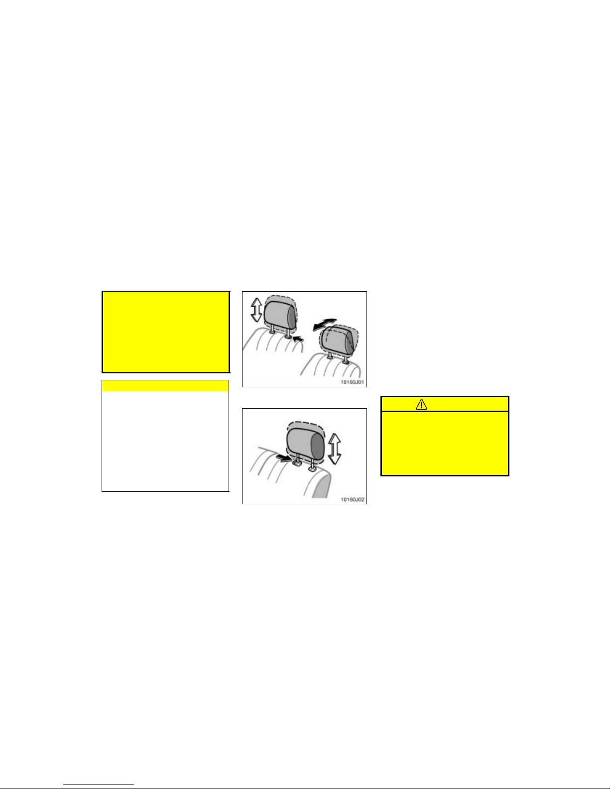
For your safety and comfort, adjust the
head restraint before driving.
To raise: Pull it up.
To lower: Push it down while pressing the
lock release button.
On some models, you can also move the
head restraint forward or backward. If
such adjustment is desired, pull or push
the head restraint.
The head restraint is most effective when
it is close to your head. Therefore, using
a cushion on the seatback is not recommended.
CAUTION
Adjust the center of the head re-
straint so that it is closet to the
top of your ears.
After adjusting the head restraint,
make sure it is locked in position.
Do not drive with the head re-
straints removed.
Head restraints
Page 49
’02 4Runner_U (L/O 0108)
43
2002 MY 4RUNNER_U (OM35787U)
Toyota strongly urges that the driver and
passengers in the vehicle be properly restrained at all times with the seat belts
provided. Failure to do so could increase
the chance of injury and/or the severity of
injury in accidents.
Child. Use a child restraint system appropriate for the child until the child becomes large enough to properly wear the
vehicle’s seat belts. See “Child restraint”
for details.
If a child is too large for a child restraint
system, the child should sit in the rear
seat and must be restrained using the
vehicle’s seat belt. According to accident
statistics, the child is safer when properly
restrained in the rear seat than in the
front seat.
If a child must sit in the front seat, the
seat belts should be worn properly. If an
accident oc curs and the seat belts are not
worn properly, the force of the rapid inflation of the airbag may cause death or
serious injury to the child.
Do not allow the child to stand up or
kneel on either rear or front seats. An
unrestrained child could suffer serious injury o r death during emergenc y brak ing or
a collision. Also do not let the child sit on
your lap. It does not provide sufficient
restraint.
Pregnant woman. Toyota recommends t he
use of a seat belt. Ask your doctor for
specific recommendations. The lap belt
should be worn securely and as low as
possible over the hips and not on the
waist.
Injured person. Toyota recommends the
use of a seat belt. Depending on the injury, first check with your doctor for specific
recommendation.
CAUTION
Persons should ride in their seats
properly wearing their seat belts
whenever the vehicle is moving.
Otherwise, they are much more likely
to suffer serious bodily injury or
death in the event of sudden braking
or a collision.
When using the seat belts, observe
the following:
Use the belt for only one person at
a time. Do not use a single belt for
two or more people—even children.
Avoid reclining the seatbacks too
much. The seat belts provide maximum protection when the seatbacks
are in the upright position. (Refer
to the seat adjustment instructions.)
Be careful not to damage the belt
webbing or hardware. Take care that
they do not get caught or pinched
in the seat or side doors.
Inspect the belt system periodically.
Check for cuts, fraying, and loose
parts. Damaged parts should be replaced. Do not disassemble or
modify the system.
Seat belts—
—Seat belt precautions
Page 50
’02 4Runner_U (L/O 0108)
44
2002 MY 4RUNNER_U (OM35787U)
Keep the belts clean and dry. If
they need cleaning, u se a mild soap
solution or lukewarm water. Never
use bleach, dye, or abrasive cleaners—they may severely weaken the
belts. (See “Cleaning the interior”
in Section 5.)
Replace the belt assembly (includ-
ing bolts) if it has been used in a
severe impact. The entire assembly
should be replaced even if damage
is not obvious.
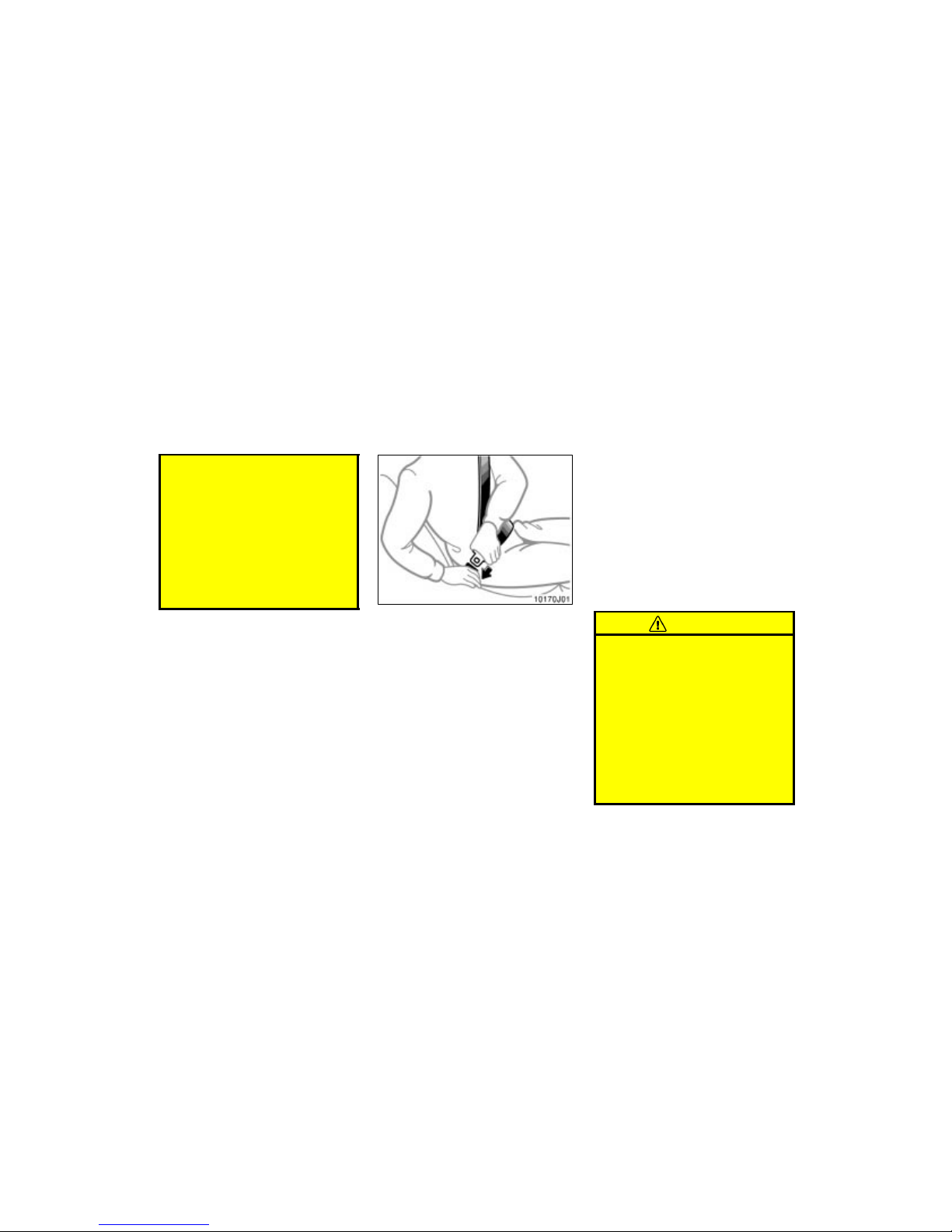
Adjust the seat as needed (front seats
only) and sit up straight and well back
in the seat. To fasten your belt, pull it
out of the retractor and insert the tab
into the buckle.
You will hear a click when the tab locks
into the buckle.
The seat belt length automatically adjusts
to your size and the seat position.
The retractor will lock the belt during a
sudden stop or on impact. It also may
lock if you lean forward too quickly. A
slow, easy motion will allow the belt to
extend, and you can move around freely.
If the seat belt cannot be pulled out of the
retractor, firmly pull the belt and release
it. You will then be able to smoothly pull
the belt out of the retractor.
When a passenger’s shoulder belt is completely extended and is then retracted
even slightly, the belt is locked in that
position and c annot be extended. Thi s feature is used to hold the child restraint
system securely. (For details, see “Child
restraint” in this section.) To free the belt
again, fully retract the belt and then pull
the belt out once more.
CAUTION
After inserting the tab, make sure
the tab and buckle are locked and
that the belt is not twisted.
Do not insert coins, clips, etc. in
the buckle as this may prevent you
from properly latching the tab and
buckle.
If the seat belt does not function
normally, immediately contact your
Toyota dealer. Do not use the seat
until the seat belt is fixed. It cannot
protect an adult occupant or your
child from injury.
—Front and rear outside seat
belts
Page 51
’02 4Runner_U (L/O 0108)
45
2002 MY 4RUNNER_U (OM35787U)
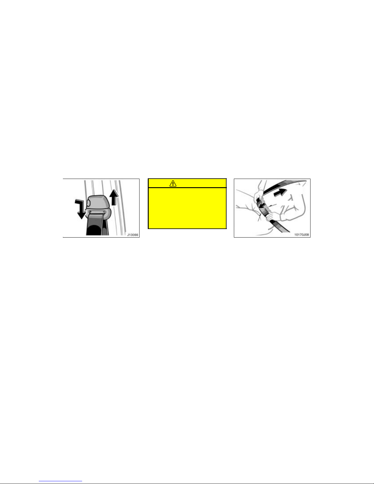
Seat belts with an adjustable shoulder
anchor—
Adjust the shoulder anchor position to
your size.
To raise: Slide the anchor up.
To lower: Push in the lock release button
and slide the anchor down.
After adjustment make sure the anchor is
locked in position.
CAUTION
Always make sure the shoulder belt
is positioned across the center of
your shoulder. The belt should be
kept away from your neck, but not
falling off your shoulder. Failure to
do so could reduce the amount of
protection in an accident and cause
serious injuries in a collision.
Ta ke u p
slack
To o h i g h
Keep as low on
hips as possible
Adjust the position of the lap and
shoulder belts.
Position the lap belt as low as possible
on your hips—not on your waist, then adjust it to a snug fit by pulling the shoulder
portion upward through the latch plate.
Page 52
’02 4Runner_U (L/O 0108)
46
2002 MY 4RUNNER_U (OM35787U)
CAUTION
Both high–positioned lap belts and
loose–fitting belts could cause serious injuries due to sliding under
the lap belt during a collision or
other unintended result. Keep the
lap belt positioned as low on hips
as possible.
For your safety, do not place the
shoulder belt under your arm.
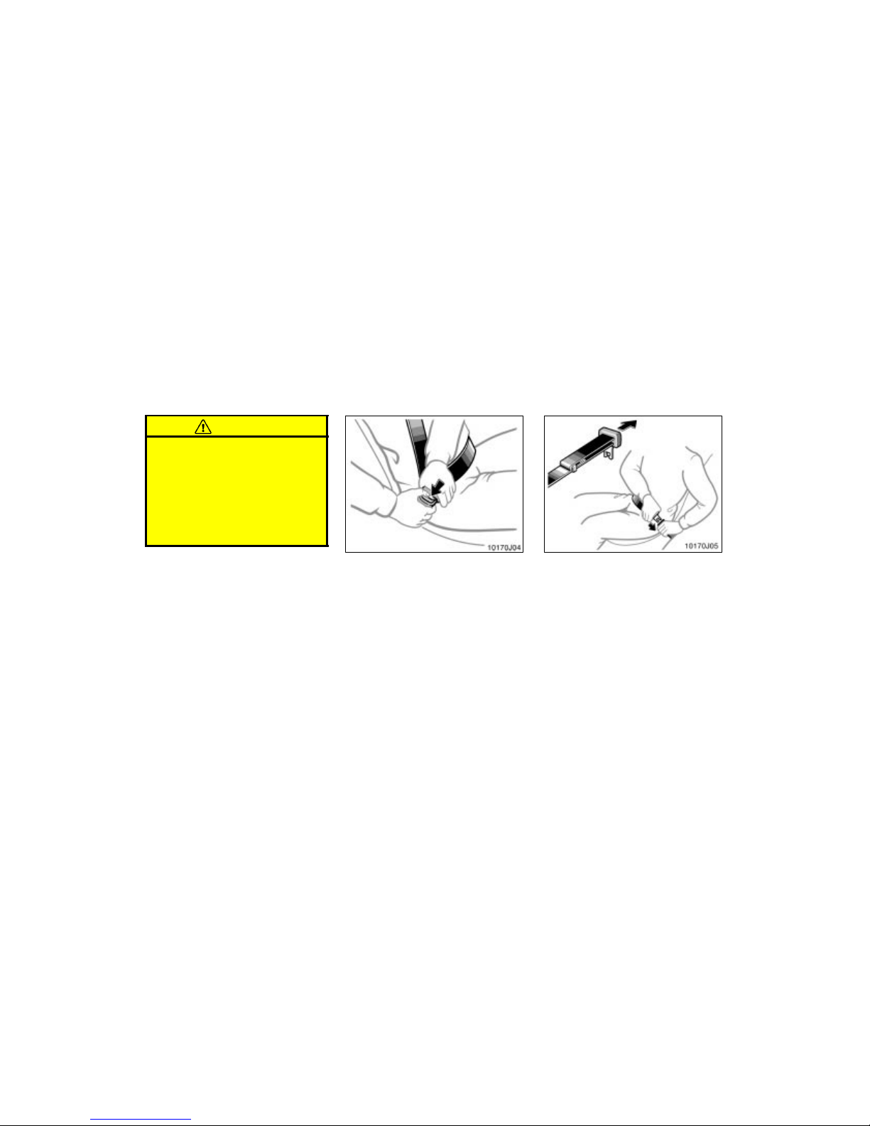
To release the belt , press the buckle–release button and allow the belt to retract.
If the belt does not retract smoothly, pull
it out and check for kinks or twists. Then
make sure it remains untwisted as it retracts.
Lengthen
Sit up straight and well back in the
seat. To fasten your belt, insert the tab
into the buckle.
You will hear a click when the tab locks
into the buckle.
If the bel t is not long enough for y ou, hold
the tab at a right angle to the belt and
pull on the tab.
—Rear center seat belt
Page 53
’02 4Runner_U (L/O 0108)
47
2002 MY 4RUNNER_U (OM35787U)
CAUTION
After inserting the tab, make sure
the tab and buckle are locked and
that the belt is not twisted.
Do not insert coins, clips, etc. in
the buckle as this may prevent you
from properly latching the tab and
buckle.
If the seat belt does not function
normally, immediately contact your
Toyota dealer. Do not use the seat
until the seat belt is fixed. It cannot
protect an adult occupant or your
child from injury.
To o h i gh
Adjust to a
snug fit
Keep as low on hips as possible
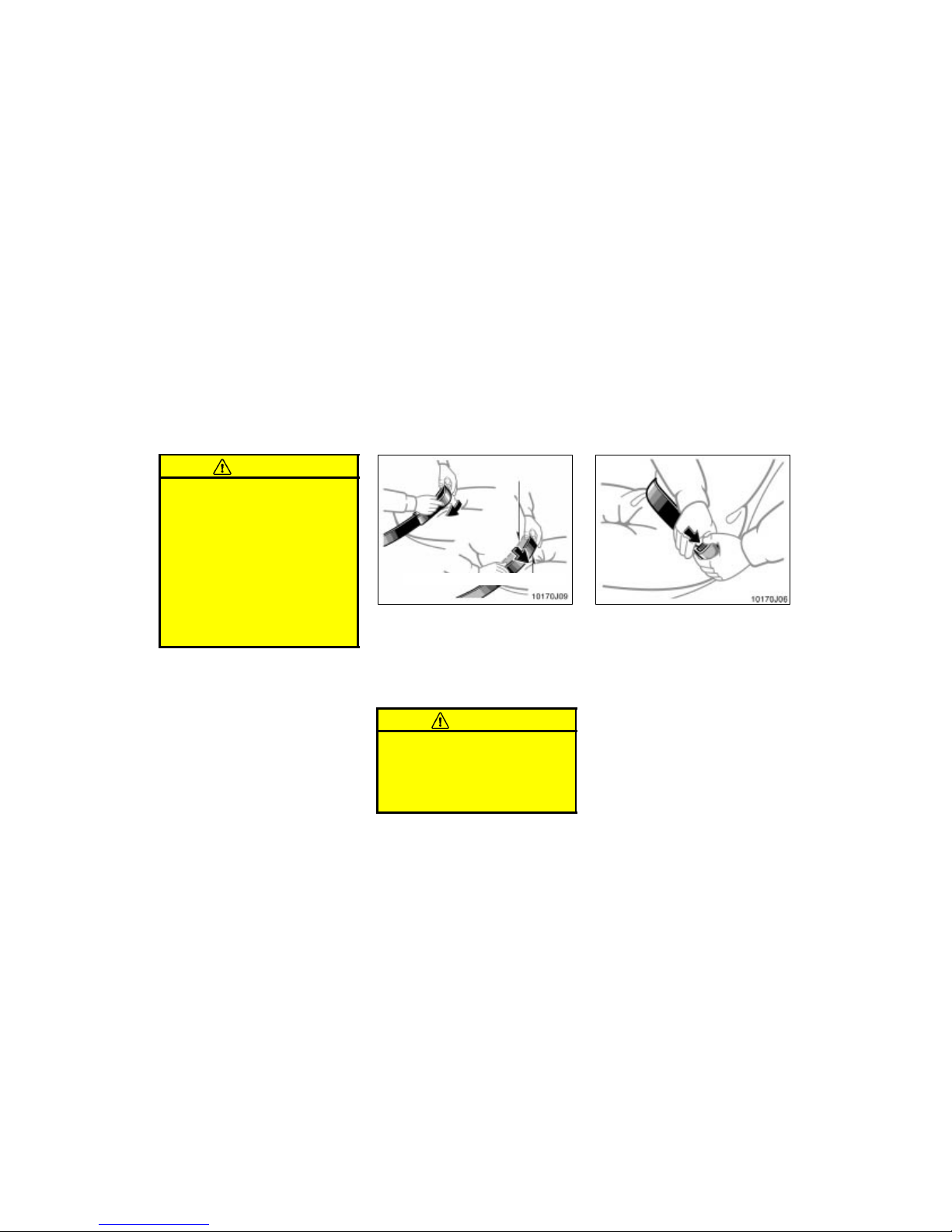
Remove excess length of the belt and
adjust the belt position.
To shorten the belt, pull the free end of
the belt.
Position the lap belt as low as possible
on your hips—not on your waist, then adjust it to a snug fit.
CAUTION
Both high–positioned and loose–fitting lap belts could cause serious injuries due to sliding under the lap
belt during a collision or other unintended result. Keep the lap belt positioned as low on hips as possible.
To release the belt , press the buckle–release button.
Page 54
’02 4Runner_U (L/O 0108)
48
2002 MY 4RUNNER_U (OM35787U)
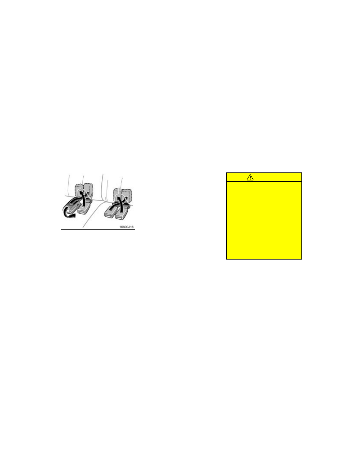
The rear seat belt and buckles can be
stowed when not in use.
Seat belt and buckles must be stowed
before you fold the seat back. ( See “Fold–
down rear seats” in this section.)
If your seat belt cannot be fastened securely because it is not long enough, a
personalized seat belt extender is available from your Toyota dealer free of
charge.
Please contact your local Toyota dealer so
that the dealer can order the proper required length for the extender. Bring the
heaviest coat you expect to wear for proper measurement and selection of length.
Additional ordering information is available
at your Toyota dealer.
CAUTION
When using the seat belt extender,
observe the following. Failure to follow these instructions could result in
less effectiveness of the seat belt restraint s ystem in case of vehicl e accident, increasing the chance of personal injury.
Never use the seat belt extender if
you can fasten the seat belt wit hout
it.
Remember that the extender pro-
vided for you may not be safe when
used on a different vehicle, or for
another person or at a different
seating position than the one originally intended for.
—Stowing rear seat belt and
buckles
—Seat belt extender
Page 55
’02 4Runner_U (L/O 0108)
49
2002 MY 4RUNNER_U (OM35787U)
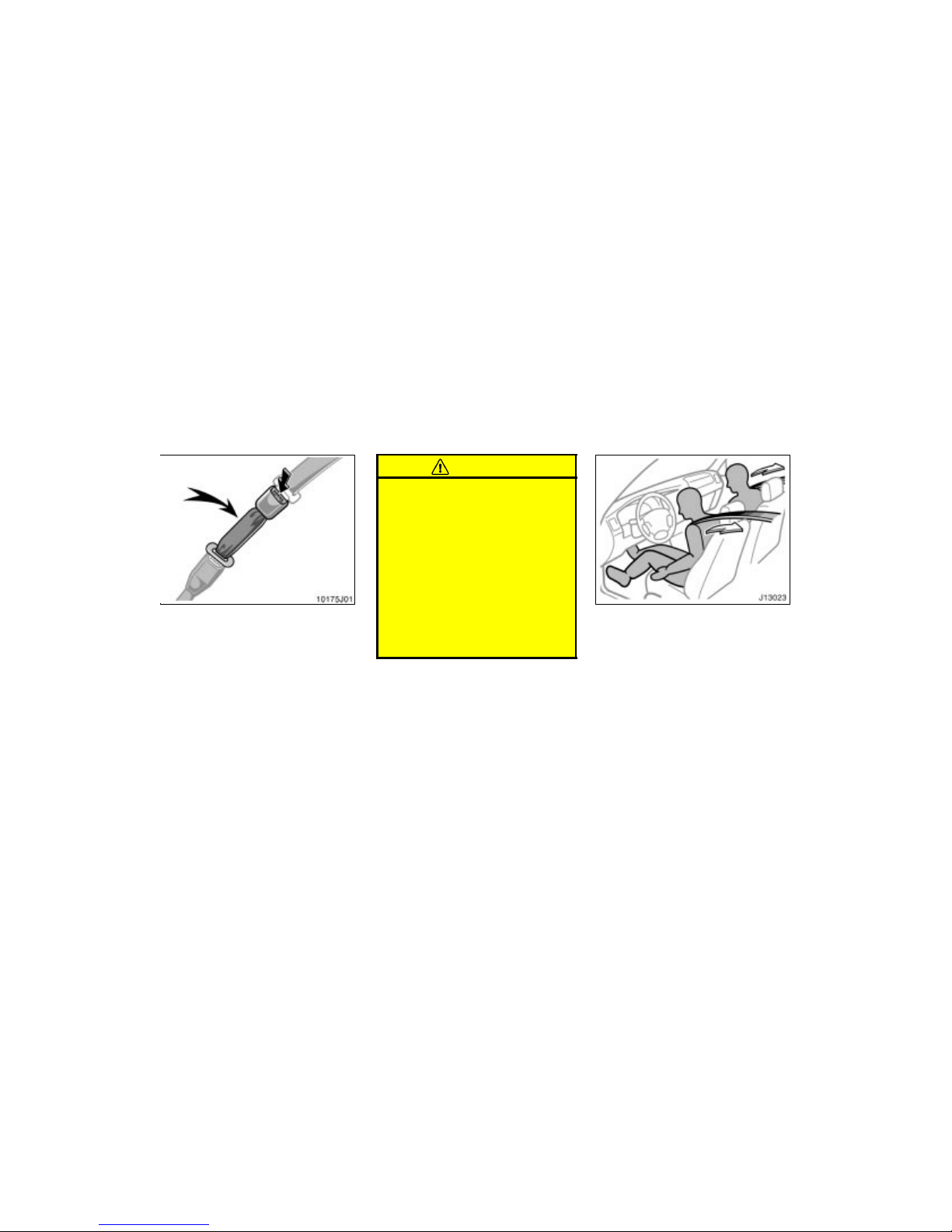
To connect the extender to the seat
belt, insert the tab into the seat belt
buckle so that the “PRESS” signs on
the buckle–release buttons of the extender and the seat belt are both facing
outward as shown.
You will hear a click when the tab locks
into the buckle.
When releasing the seat belt, press on
the buckl e–release button on the extender,
not on the seat belt. This helps prevent
damage to the vehicle interior and extender itself.
When not in use, remove the extender
and store in the vehicle for future use.
CAUTION
After inserting the tab, make sure
the tab and buckle are locked and
that the seat belt extender is not
twisted.
Do not insert coins, clips, etc. in
the buckle as this may prevent you
from properly latching the tab and
buckle.
If the seat belt does not function
normally, immediately contact your
Toyota dealer. Do not use the seat
until the seat belt is fixed. It cannot
protect an adult occupant or your
child from injury.
The driver and front passenger’s seat
belt pretensioners are designed to be
activated in response to a severe frontal impact.
When the airbag sensor detects the shock
of a severe frontal impact, the front seat
belts are quickly drawn back in by the
retractors so that the belts snugly restrain
the front seat occupants.
The front seat belt pretensioners are activated even with no passenger in the front
seat.
Collisions occurring at certain speeds and
angles may cause the seat belt pretensioners and SRS airbags not to operate
all together.
—Front seat belt
pretensioners
Page 56
’02 4Runner_U (L/O 0108)
50
2002 MY 4RUNNER_U (OM35787U)
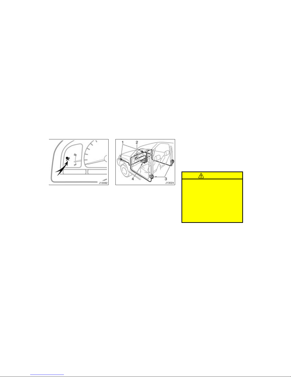
This indicator comes on when the ignition key is turned to the “ON” position.
It goes off after about 6 seconds. This
means the front seat belt pretensioners
are operating properly.
This warning light system monitors the
airbag sensor assembly, front airbag sensors, front seat belt pretensioner assemblies, warning light, inflators, interconnecting wiring and power sources. (For details,
see “Service reminder indicators and
warning buzzers” in Section 1–5.)
The front seat belt pretensioner system
mainly consists of the following components and their locations are shown in the
illustration.
1. Front airbag sensors
2. SRS warning light
3. Front seat belt pretensioner assemblies
4. Airbag sensor assembly
The front seat belt pretensioners are controlled by the airbag sensor assembly. The
airbag sensor assembly consists of a safing sensor and airbag sensor.
When the front seat belt pretensioners are
activated, an operating noise may be
heard and a small amount of smoke–like
gas may be released. This gas is harmless and does not indicate that a fire is
occurring.
Once the front seat belt pretensioners
have been activated, the seat belt retractors remain locked.
CAUTION
Do not modify, remove, strike or open
the front seat belt pretensioner assemblies, airbag sensor or surrounding area or wiring. Doing any of
these may cause sudden operation of
the front seat belt pretensioners or
disable the system, which could result in death or serious injury.
Failure to follow these instructions
can result in death or serious injuries.
Page 57
’02 4Runner_U (L/O 0108)
51
2002 MY 4RUNNER_U (OM35787U)
NOTICE
Do not perform any of the following
changes without consulting your
Toyota dealer. Such changes can
interfere with proper operation of the
front seat belt pretensioners in some
cases.
Installation of electronic devices
such as a mobile two–way radio,
cassette tape player or compact
disc player
Repairs on or near the front seat
belt retractor assemblies
Modification of the suspension system
Modification of the front end structure
Attachment of a grille guard (bull
bar, kangaroo bar, etc.), snowplow,
winches or any other equipment to
the front end
Repairs made on or near the front
fenders, front end structure or console
This front seat belt pretensioner system
has a service reminder indicator to inform
the driver of operating problems. If any of
the following conditions occurs, this
indicates a malfunction of the airbags or
pretensioners. Contact your Toyota dealer
as soon as possible to service the
vehicle.
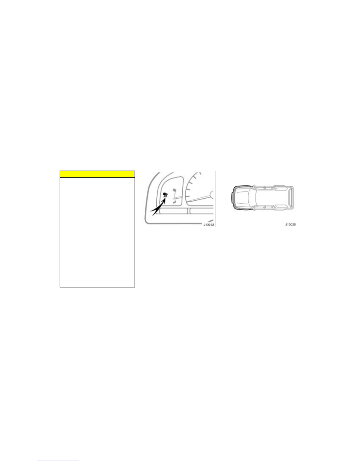
The light does not come on when the
ignition key is turned to the “ON” position, or the light remains on.
The light comes on or flashes while
driving.
If either front seat belt does not retract
or cannot be pulled out due to a malfunction or activation of the relevant
front seat belt pretensioner.
In the following cases, contac t your Toyota
dealer as soon as possible:
The front part of the vehicle (shaded
in the illustration) was involved in an
accident that was not severe enough to
cause the front seat belt pretensioners
to operate.
Either front seat belt pretensioner as-
sembly or surrounding area is
scratched, cracked, or otherwise damaged.
Page 58
’02 4Runner_U (L/O 0108)
52
2002 MY 4RUNNER_U (OM35787U)
The SRS (Supplemental Restraint System) airbags are designed to provide
further protection for the driver and
front passenger in addition to the primary safety protection provided by the
seat belts.
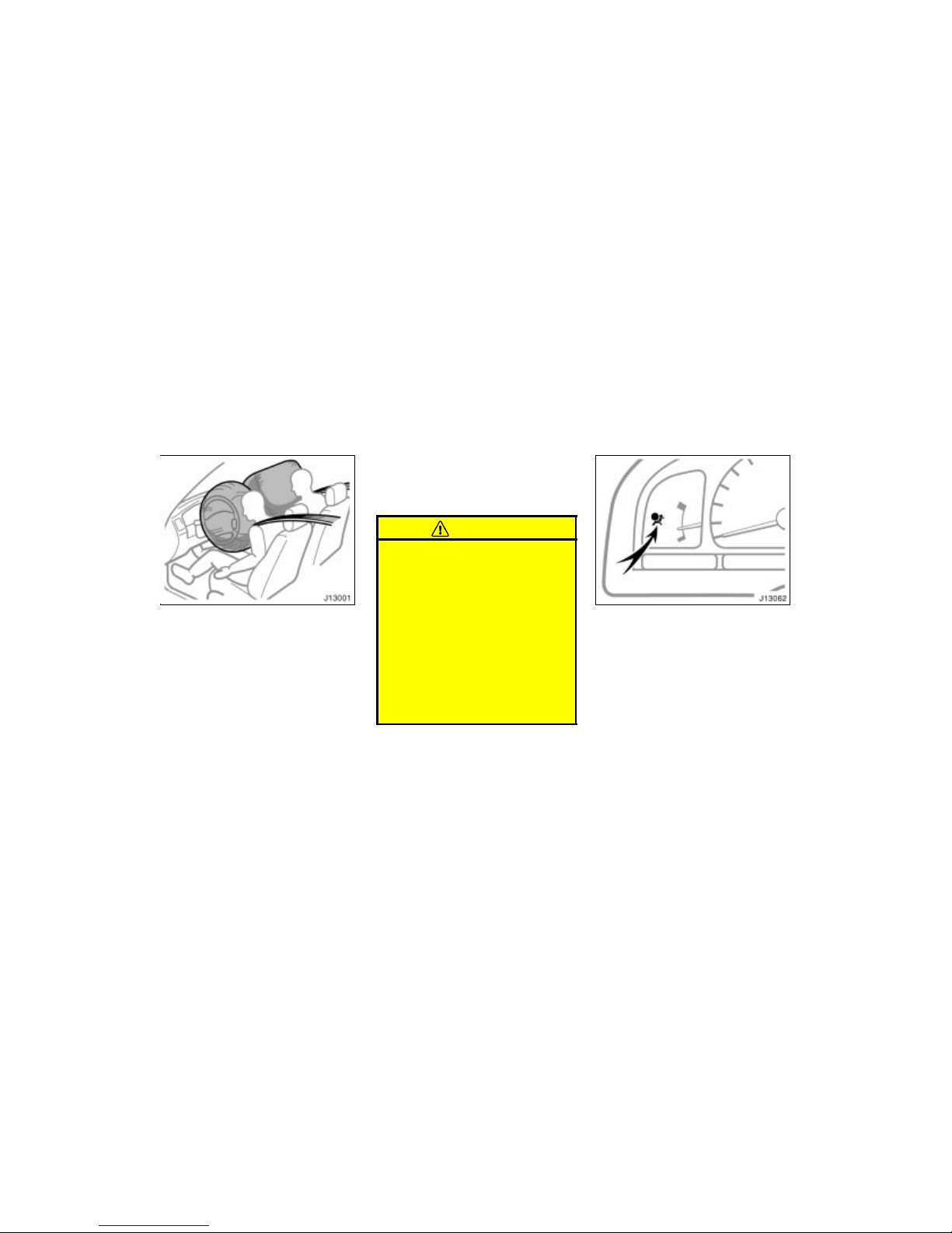
In response to a severe frontal impact,
the SRS airbags work together with the
seat belts to help reduce injury by inflating. The SRS airbags help to reduce injuries mainly to the driver’s or front passenger’s head or chest caused by directly
hitting the steering wheel or dashboard.
The front passenger airbag is activated
even with no passenger in the front seat.
Be sure to wear your seat belt properly.
Your vehicle is equipped with a crash
sensing and diagnostic module, which will
record the use of the seat belt restraint
system by the driver and the front passenger when the SRS airbags are inflated.
CAUTION
The driver or front passenger who is
too close to the steering wheel or
dashboard during airbag deployment
can be killed or seriously injured. Toyota strongly recommends that:
The driver sit as far back as pos-
sible from the steering wheel while
still maintaining control of the vehicle.
The front passenger sit as far back
as possible from the dashboard.
All vehicle occupants be properly
restrained using the available seat
belts.
This indicator comes on when the ignition key is turned to the “ON” position.
It goes off after about 6 seconds. This
means the SRS airbags are operating
properly.
This warning light system monitors the
airbag sensor assembly, front airbag sensors, front seat belt pretensioner assemblies, inflators, warning light, interconnecting wiring and power sources. (For details,
see “Service reminder indicators and
warning buzzers” in Section 1–5.)
SRS driver airbag and front
passenger airbag
Page 59
’02 4Runner_U (L/O 0108)
53
2002 MY 4RUNNER_U (OM35787U)
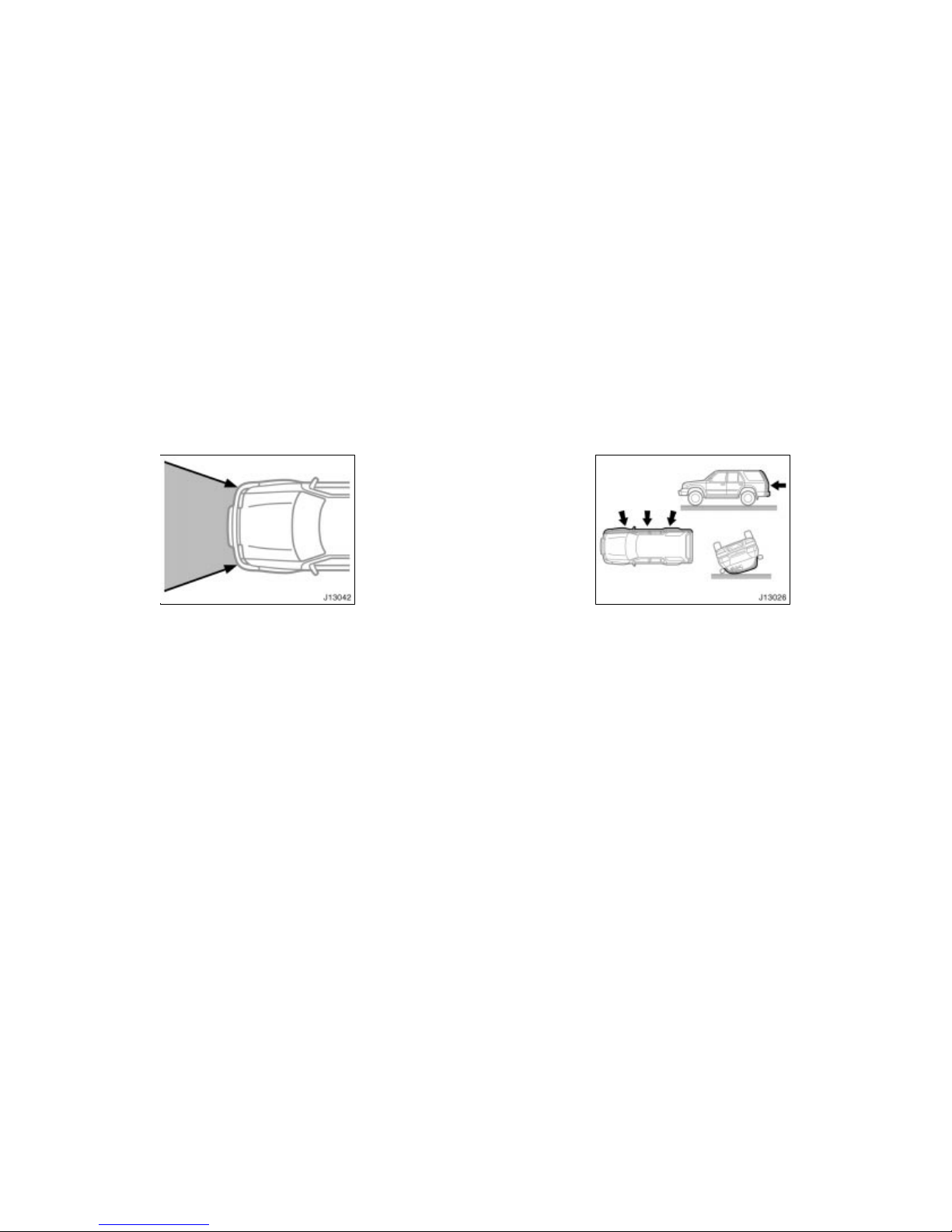
The SRS airbag system is designed to
activate in response to a severe frontal
impact within the shaded area between
the arrows in the illustration.
The SRS airbags will deploy if the severity of the impact is above the designed
threshold level, comparable to an approximate 25 km/h (15 mph) collision when
impacting straight into a fixed barrier that
does not move or deform.
If the severity of the impact is below the
above threshold level, the SRS airbags
may not deploy.
However, this threshold velocity will be
considerably higher if the vehicle strikes
an object, such as a parked vehicle or
sign pole, which can move or deform on
impact, or if it is involved in an underride
collision (e.g. a collision in which the nose
of the vehicle “underrides”, or goes under,
the bed of a truck, etc.).
It is possible that in some collisions at the
lower zone of airbag sensor detection and
activation the SRS airbags and seat belt
pretensioners will not operate all together.
For the safety of all occupants, always
wear your seat belts properly.
Collision from the rear
Collision from the side
Vehicle rollover
The SRS airbags are not designed to
inflate if the vehicle is involved in a
side or rear collision, if it rolls over, or
if it is involved in a low–speed frontal
collision.
Page 60
’02 4Runner_U (L/O 0108)
54
2002 MY 4RUNNER_U (OM35787U)
Hitting a curb,
edge of pavement
or hard material
Falling into or
jumping over a
deep hole
Landing hard or vehicle falling
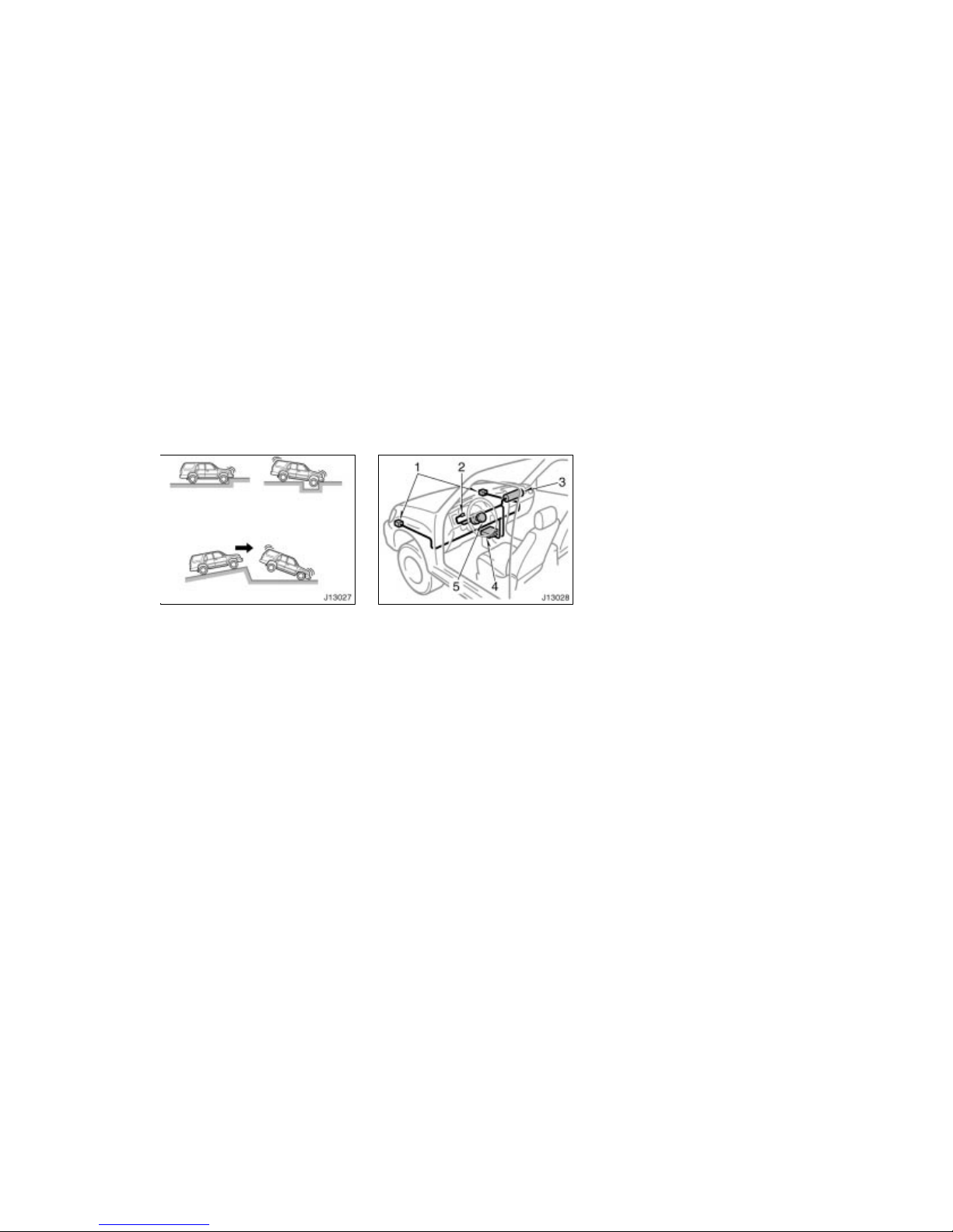
The SRS airbags may deploy if a serious impact occurs to the underside of
your vehicle. Some examples are shown
in the illustration.
The SRS airbag system consists mainly of
the following components, and their locations are shown in the illustration.
1. Front airbag sensors
2. SRS warning light
3. Airbag module for front passenger
(airbag and inflator)
4. Airbag sensor assembly
5. Airbag module for driver
(airbag and inflator)
The airbag sensor assembly consists of a
safing sensor and airbag sensor.
In a severe frontal impact, the sensors
detect deceleration and the system triggers the airbag inflators. Then a chemical
reaction in the inflators quickly fills the
airbags wit h non–toxic g as to help restrain
the forward motion of the occupants.
When the airbags inflate, they produce a
fairly loud noise and release some smoke
and residue along with non–toxic gas. This
does not indicate a fire. This gas is normally harmless; however, for those who
have delicate skin, it may cause a minor
skin irritation. Be sure to wash off any
residue as soon as possible to prevent
any potential skin irritation.
Deployment of the airbags happens in a
fraction of a second, so the airbags must
inflate with considerable force. While the
system is designed to reduce serious injuries, it may also cause minor burns or
abrasions and swelling.
Parts of the ai rbag module (steering wheel
hub, dashboard) may be hot for several
minutes, but the airbags themselves will
not be hot. The airbags are designed to
inflate only once.
Page 61
’02 4Runner_U (L/O 0108)
55
2002 MY 4RUNNER_U (OM35787U)
A crash severe enough to inflate the airbags may break the windshield as the
vehicle buckles. In vehicles with a passenger airbag the windshield may also be
damaged by absorbing some of the force
of the inflating airbag.
CAUTION
The SRS airbag system is designed
only as a supplement to the primary protection of the driver side and
front passenger side seat belt systems. The front seat occupants can
be killed or seriously injured by the
inflating airbags if they do not wear
the available seat belts properly.
During sudden braking just before
a collision, an unrestrained driver
or front passenger can move forward into direct contact with or
close proximity to the airbag which
may then deploy during the collision. To ensure maximum protection
in an accident, the driver and all
passengers in the vehicle must
wear their seat belts properly. Wearing a seat belt properly during an
accident reduces the chances of
death or serious injury or being
thrown out of the vehicle. For
instructions and precautions concerning the seat belt system, see
“Seat belts” in this section.
Improperly seated and/or restrained
infants and children can be killed
or seriously injured by the deploying airbag. An infant or child who
is too small to use a seat belt
should be properly secured using a
child restraint system. Toyota
strongly recommends that all infants and children be placed in the
rear seat of the vehicle and properly restrained. The rear seat is the
safest for infants and children. For
instructions concerning the installation of a child restraint system, see
“Child restraint” in this section.
Page 62
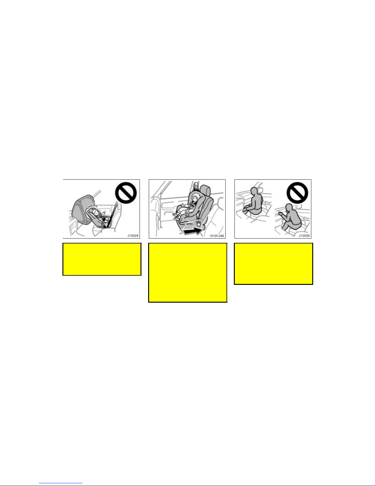
’02 4Runner_U (L/O 0108)
56
2002 MY 4RUNNER_U (OM35787U)
Never install a rear–facing child re-
straint system on the front passenger seat because the force of the
rapid inflation of the front passenger airbag can cause death or serious injury to the child.
Move seat
fully back
A forward–facing chil d restraint sys-
tem should be allowed to be
installed on the front passenger
seat only when it is unavoidable.
Always move the seat as far back
as possible, because the force of
the deploying front passenger airbag could cause death or serious
injury to the child. For instructions
concerning the installation of a
child restraint system, see “Child
restraint” in this section.
Do not sit on the edge of the seat
or lean over the dashboard when
the vehicle is in use. The airbags
inflate with considerable speed and
force; you may be killed or seriously injured. Sit up straight and well
back in the seat, and always use
your seat belt properly.
Page 63
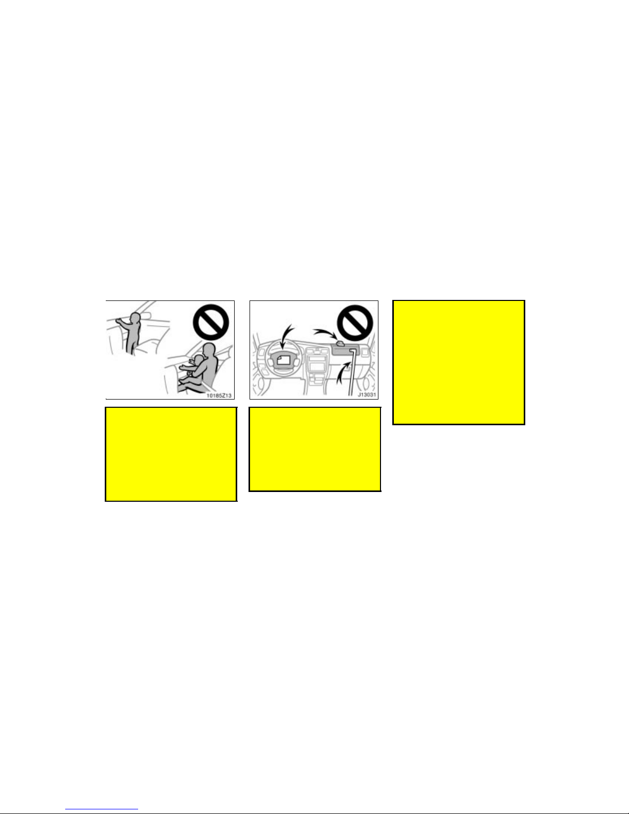
’02 4Runner_U (L/O 0108)
57
2002 MY 4RUNNER_U (OM35787U)
Do not allow a child to stand up,
or to kneel on the front passenger
seat. The airbag inflates with considerable speed and force; the child
may be killed or seriously injured.
Do not hold a child on your lap or
in your arms. Use a child restraint
system in the rear seat. F or instructions concerning the installation of
a child restraint system, see “Child
restraint” in this section.
Do not put objects or your pets on
or in front of the dashboard or
steering wheel pad that houses the
airbag system. They might restrict
inflation or cause death or serious
injury as they are projected rearward by the force of deploying airbags. Likewise, the driver and front
passenger should not hold things in
their arms or on their knees.
Do not modify or remove any wir-
ing. Do not modify, remove, strike
or open any components such as
the steering wheel pad, steering
wheel, column cover, front passenger airbag cover, front passenger
airbag or airbag sensor assembly.
Doing so may cause sudden SRS
airbag inflation or disable the system, which could result in death or
serious injury.
Failure to follow these instructions
can result in death or serious injury.
Consult your Toyota dealer about any
repairs and modifications.
Page 64
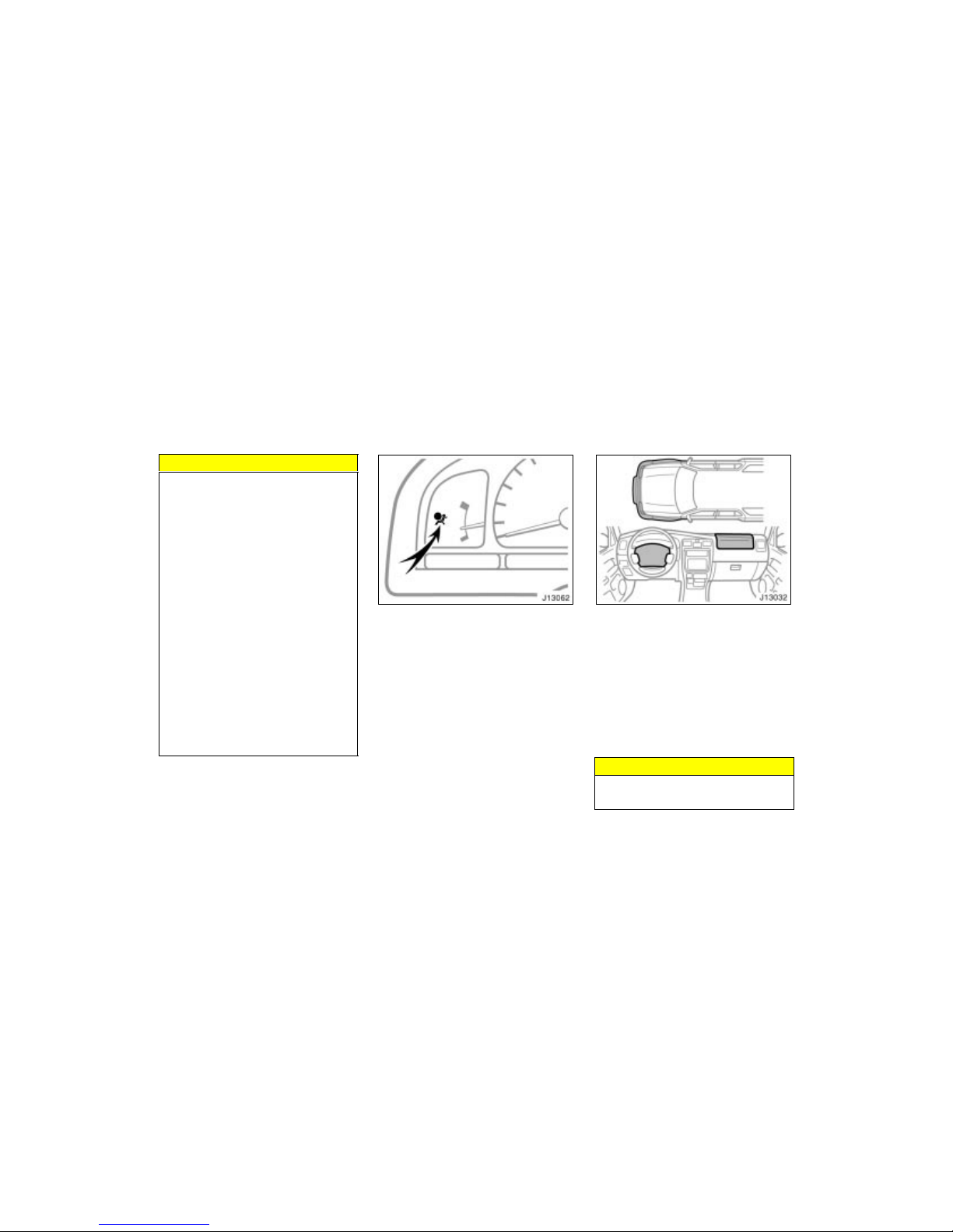
’02 4Runner_U (L/O 0108)
58
2002 MY 4RUNNER_U (OM35787U)
NOTICE
Do not perform any of the following
changes without consulting your
Toyota dealer. Such changes can interfere with proper operation of the
SRS airbag system in some cases.
Installation of electronic devices
such as a mobile two–way radio,
cassette tape player or compact
disc player
Modification of the suspension system
Modification of the front end structure
Attachment of a grille guard (bull
bar, kangaroo bar, etc.), snowplow,
winches or any other equipment to
the front end
Repairs made on or near the front
fenders, front end structure, console, steering column, steering
wheel or dashboard near the front
passenger airbag
This SRS airbag system has a service
reminder indicator to inform the driver of
operating problems. If either of the following conditi ons occurs, this indicates a malfunction of the airbags. Contact your
Toyota dealer as soon as possible to service the vehicle.
The light does not come on when the
ignition key is turned to the “ON” position, or the light remains on.
The light comes on while driving.
In the following cases, contac t your Toyota
dealer as soon as possible:
The SRS airbags have been inflated.
The front of the vehicle (shaded in the
illustration) was involved in an accident
that was not severe enough to cause
the SRS airbags to inflate.
The pad section of the steering wheel
or front passenger airbag cover
(shaded in the illustration) is scratched,
cracked, or otherwise damaged.
NOTICE
Do not disconnect the battery cables
before contacting your Toyota dealer.
Page 65
’02 4Runner_U (L/O 0108)
59
2002 MY 4RUNNER_U (OM35787U)
Toyota strongly urges the use of child
restraint systems for children small
enough to use them.
The laws of all fifty states in the U.S.A.
and Canada now require the use of a
child restraint system.
Your vehicle conforms to SAE J1819.
If a child is too large for a child restraint
system, the child should sit in the rear
seat and must be restrained using the
vehicle’s seat belt. See “Seat belts” for
details.
CAUTION
For effective protection in automo-
bile accidents and sudden stops, a
child must be properly restrained,
using a seat belt or child restraint
system depending on the age and
size of the child. Holding a child in
your arms is not a substitute for a
child restraint system. In an accident, the child can be crushed
against the windshield, or between
you and the vehicle’s interior.
Toyota strongly urges use of a
proper child restraint system which
conforms to the size of the child,
and is put on the rear seat. According to accident statistics, the child
is safer when properly restrained in
the rear seat than in the front seat.
Never install a rear–facing child re-
straint system on the front seat. In
the event of an accident, the force
of the rapid inflation of the airbag
can cause death or serious injury if
a rear–facing child restraint system
is installed on the front seat.
Unless it is unavoidable, do not
install a forward–facing child restraint system on the front seat.
A forward–facing chil d restraint sys-
tem should be allowed to be
installed on the front seat only
when it is unavoidable. Always
move the seat as far back as possible, because the force of the deploying airbag c ould cause death or
serious injury to the child.
Make sure that you have complied
with all installation instructions provided by the child restraint
manufacturer and t hat the system is
properly secured.
Child restraint—
—Child restraint precautions
Page 66
’02 4Runner_U (L/O 0108)
60
2002 MY 4RUNNER_U (OM35787U)
A child restraint system for a small
child or baby must itself be properly
restrained on the seat with either the
lap belt or the lap portion of the lap/
shoulder belt. You must carefully consult the manufacturer’s instructions
which accompany the child restraint
system.
To provide proper restraint, use a child
restraint system following the manufacturer’s instructions about the appropriate age
and size of the child for the child restraint
system.
Install the child restraint system correctly
following the instructions provided by its
manufacturer of the system. General
directions are also provided under the following illustrations.
The child restraint system should be
installed on the rear seat. According to
accident statistics, the child is safer when
properly restrained in the rear seat than
in the front seat.
CAUTION
Never install a rear–facing child re-
straint system on the front seat. In
the event of an accident, the force
of the rapid inflation of the airbag
can cause death or serious injury if
a rear–facing child restraint system
is installed on the front seat.
Unless it is unavoidable, do not
install a forward–facing child restraint system on the front seat.
A forward–facing chil d restraint sys-
tem should be allowed to be
installed on the front seat only
when it is unavoidable. Always
move the seat as far back as possible, because the force of the deploying airbag c ould cause death or
serious injury to the child.
After installing the child restraint
system, make sure it is secured in
place following the manufacturer’s
instructions. If it is not restrained
securely, it may cause death or serious injury to the child in the
event of a sudden stop or accident.
When not using the child restraint system,
keep it secured with the seat belt or place
it somewhere other than the passenger
compartment. This will prevent it from injuring passengers in the event of a sudden stop or accident.
—Child restraint system
Page 67
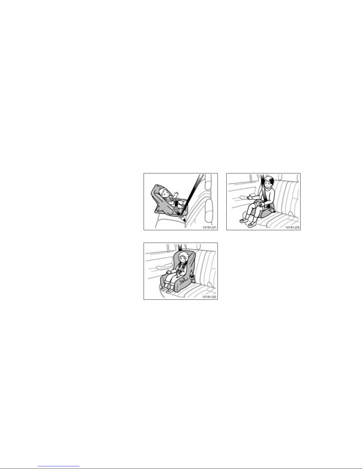
’02 4Runner_U (L/O 0108)
61
2002 MY 4RUNNER_U (OM35787U)
Child restraint systems are classified into
the following 3 types depending on the
child’s age and size.
(A) Infant seat
(B) Converti ble seat
(C) Boos ter seat
Install the child restraint system following
the instructions provided by its manufacturer.
(A) Infant seat
(B) Convertible seat
(C) Booster seat
—Types of child restraint
system
Page 68
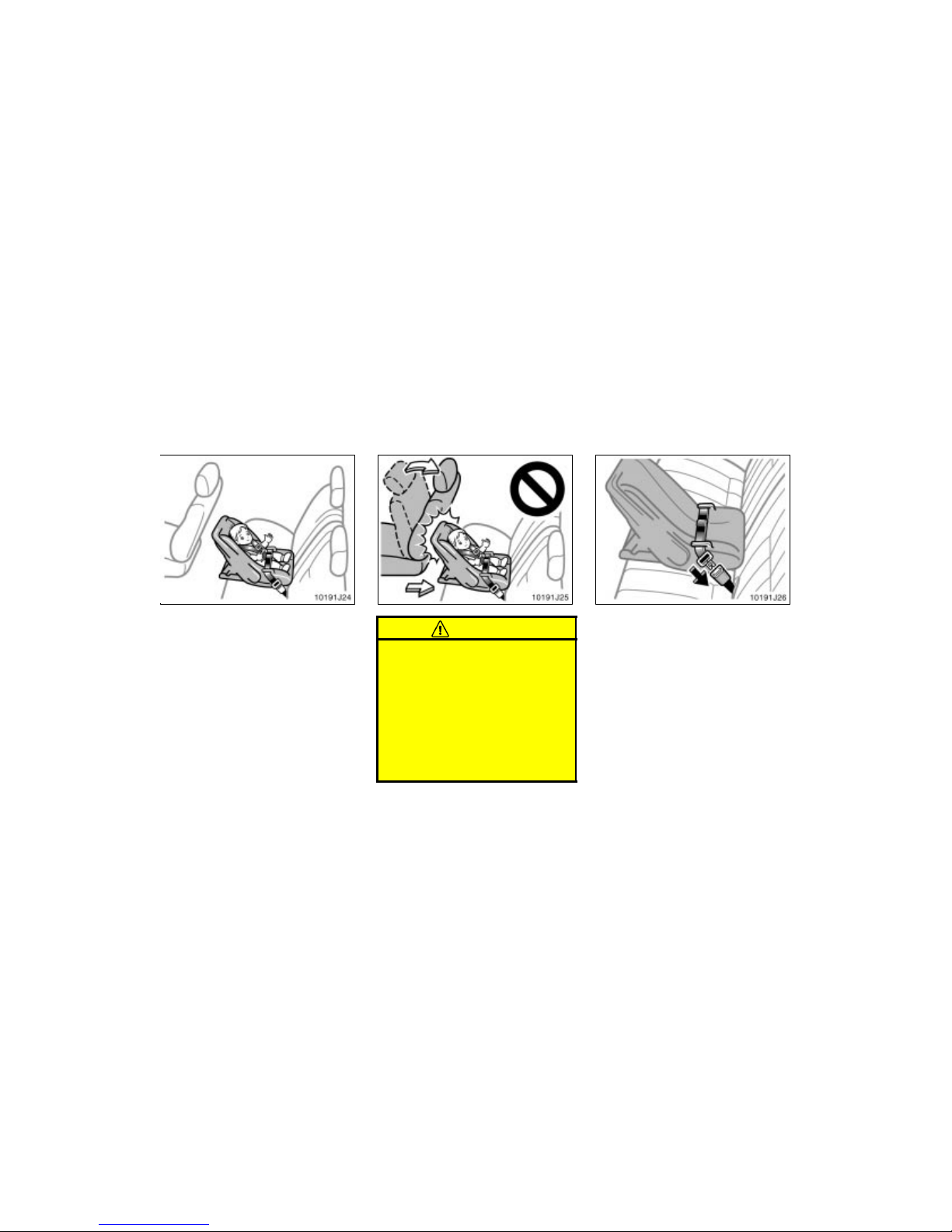
’02 4Runner_U (L/O 0108)
62
2002 MY 4RUNNER_U (OM35787U)
(A) INFANT SEAT INSTALLATION
An infant seat is used in rear–facing
position only.
CAUTION
Do not install a rear–facing child
restraint system on the rear seat if
it interferes with the lock mechanism of the front seats. This can
cause death or serious injury to the
child and front passenger in case
of sudden braking or a collision.
If the driver’s seat position does
not allow sufficient space for safe
installation, install the child restraint system at another position.
1. Run the center lap belt through or
around the infant seat following the
instructions provided by its manufacturer and insert the tab into the buckle
taking care not to twist the lap belt.
—Installation with 2–point
type seat belt
Page 69
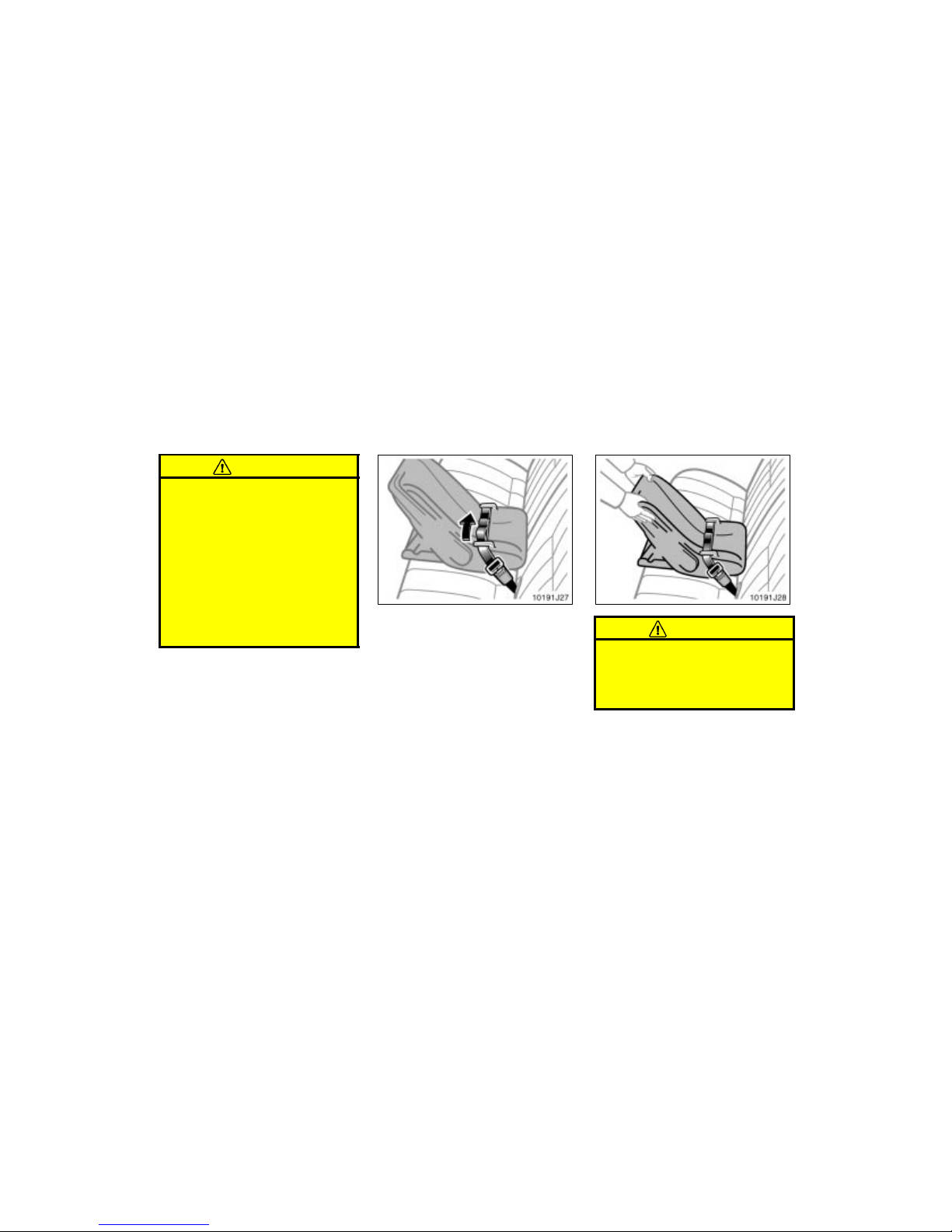
’02 4Runner_U (L/O 0108)
63
2002 MY 4RUNNER_U (OM35787U)
CAUTION
After inserting the tab, make sure
the tab and buckle are locked and
that the lap belt is not twisted.
Do not insert coins, clips, etc. in
the buckle as this may prevent you
from properly latching the tab and
buckle.
If the seat belt does not function
normally, it cannot protect your
child from injury. Contact your
Toyota dealer immediately. Do not
use the child restraint seat until the
seat belt is fi xed.
2. While pressing the infant seat firmly
against the seat cushion and seatback,
tighten the lap belt by pulling its free
end to hold the infant seat securely.
CAUTION
Push and pull the child restraint system in different directions to be sure
it is secure. Follow all the installation
instructions provided by its manufacturer.
Page 70
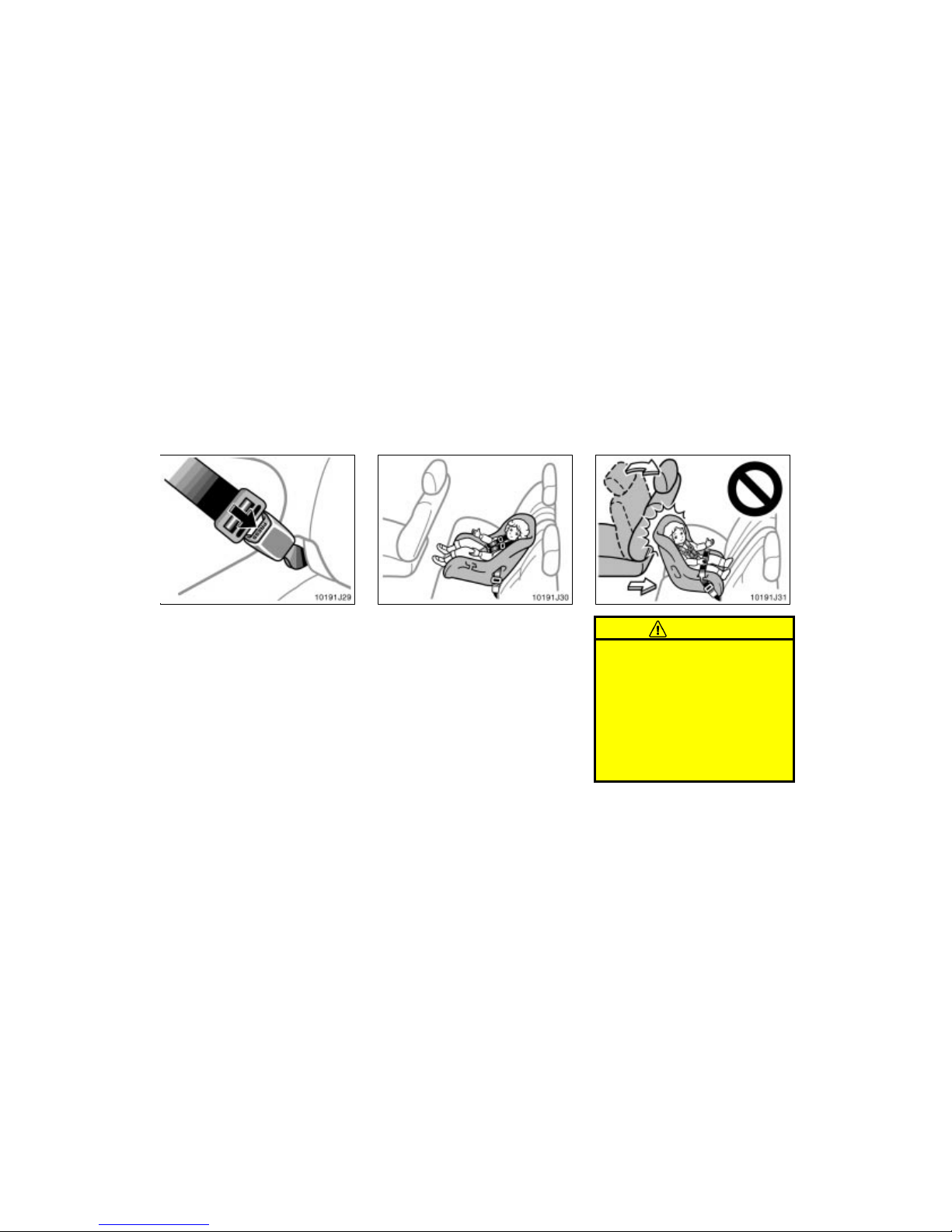
’02 4Runner_U (L/O 0108)
64
2002 MY 4RUNNER_U (OM35787U)
3. To remove the infant seat, press the
buckle–release button.
(B) CONVERTIBLE SEAT INSTALLATION
A convertible seat is used in forward–
facing or rear–facing position depending on the child’s age and size. When
installing, follow the manufacturer’s
instructions about the applicable child’s
age and size as well as direction for
installing of the child restraint system.
CAUTION
Do not install a rear–facing child
restraint system on the rear seat if
it interferes with the lock mechanism of the front seats. This can
cause death or serious injury to the
child and front passenger in case
of sudden braking or a collision.
If the driver’s seat position does
not allow sufficient space for safe
installation, install the child restraint system at another position.
Page 71
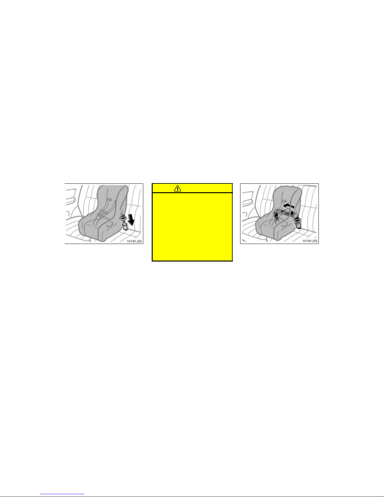
’02 4Runner_U (L/O 0108)
65
2002 MY 4RUNNER_U (OM35787U)
1. Run the center lap belt through or
around the convertible seat following
the instructions provided by its
manufacturer and insert the tab into
the buckle taking care not to twist the
lap belt.
CAUTION
After inserting the tab, make sure
the tab and buckle are locked and
that the lap belt is not twisted.
Do not insert coins, clips, etc. in
the buckle as this may prevent you
from properly latching the tab and
buckle.
If the seat belt does not function
normally, it cannot protect your
child from injury. Contact your
Toyota dealer immediately. Do not
use the child restraint seat until the
seat belt is fi xed.
2. While pressing the convertible seat
firmly against the seat cushion and
seatback, tighten the lap belt by pulling
its free end to hold the convertible seat
securely.
Page 72
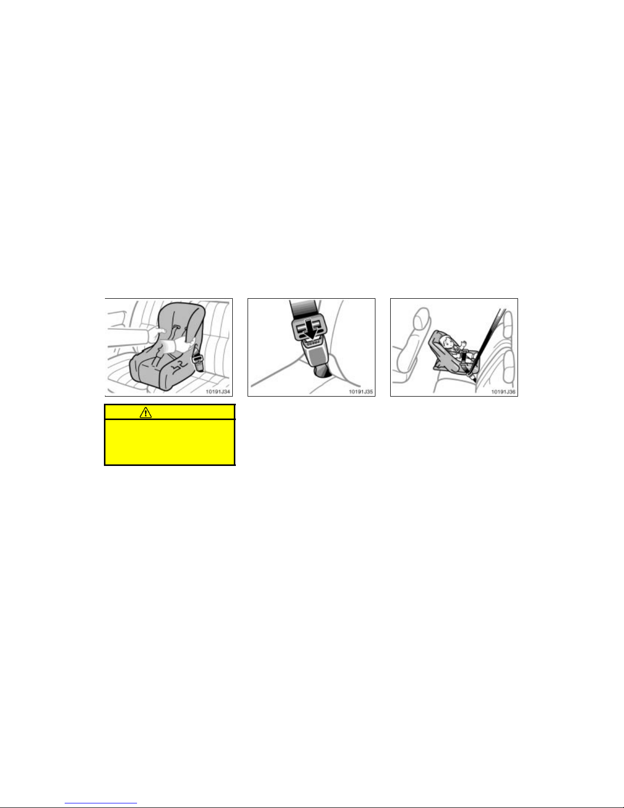
’02 4Runner_U (L/O 0108)
66
2002 MY 4RUNNER_U (OM35787U)
CAUTION
Push and pull the child restraint system in different directions to be sure
it is secure. Follow all the installation
instructions provided by its manufacturer.
3. To remove the convertible seat, press
the buckle–release button.
(A) INFANT SEAT INSTALLATION
An infant seat is used in rear–facing
position only.
—Installation with 3–point
type seat belt
Page 73
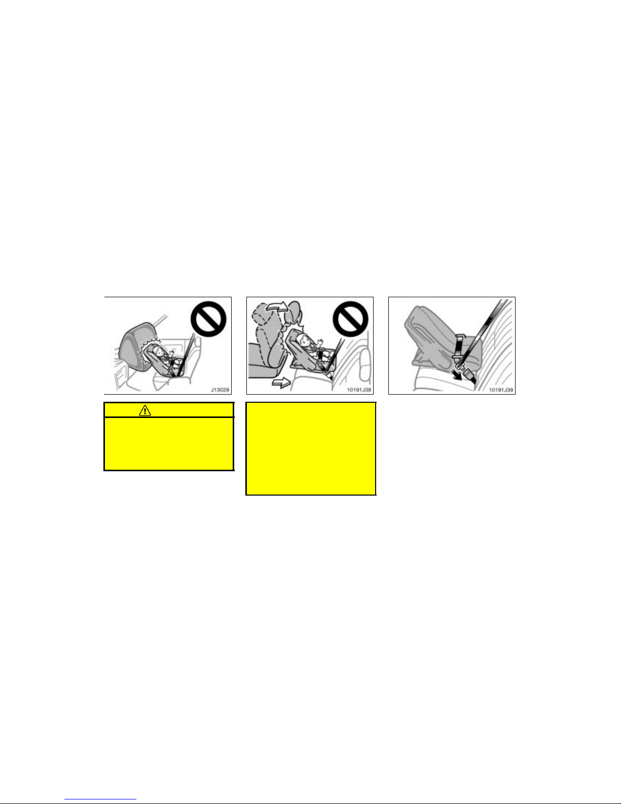
’02 4Runner_U (L/O 0108)
67
2002 MY 4RUNNER_U (OM35787U)
CAUTION
Never install a rear–facing child re-
straint system on the front passenger seat because the force of the
rapid inflation of the front passenger airbag can cause death or serious injury to the child.
Do not install a rear–facing child
restraint system on the rear seat if
it interferes with the lock mechanism of the front seats. This can
cause death or serious injury to the
child and front passenger in case
of sudden braking or a collision.
If the driver’s seat position does
not allow sufficient space for safe
installation, do not install the child
restraint system on the left seat.
1. Run the lap and shoulder belt through
or around the infant seat following the
instructions provided by its manufacturer and insert the tab into the buckle
taking care not to twist the belt. Keep
the lap portion of the belt tight.
Page 74
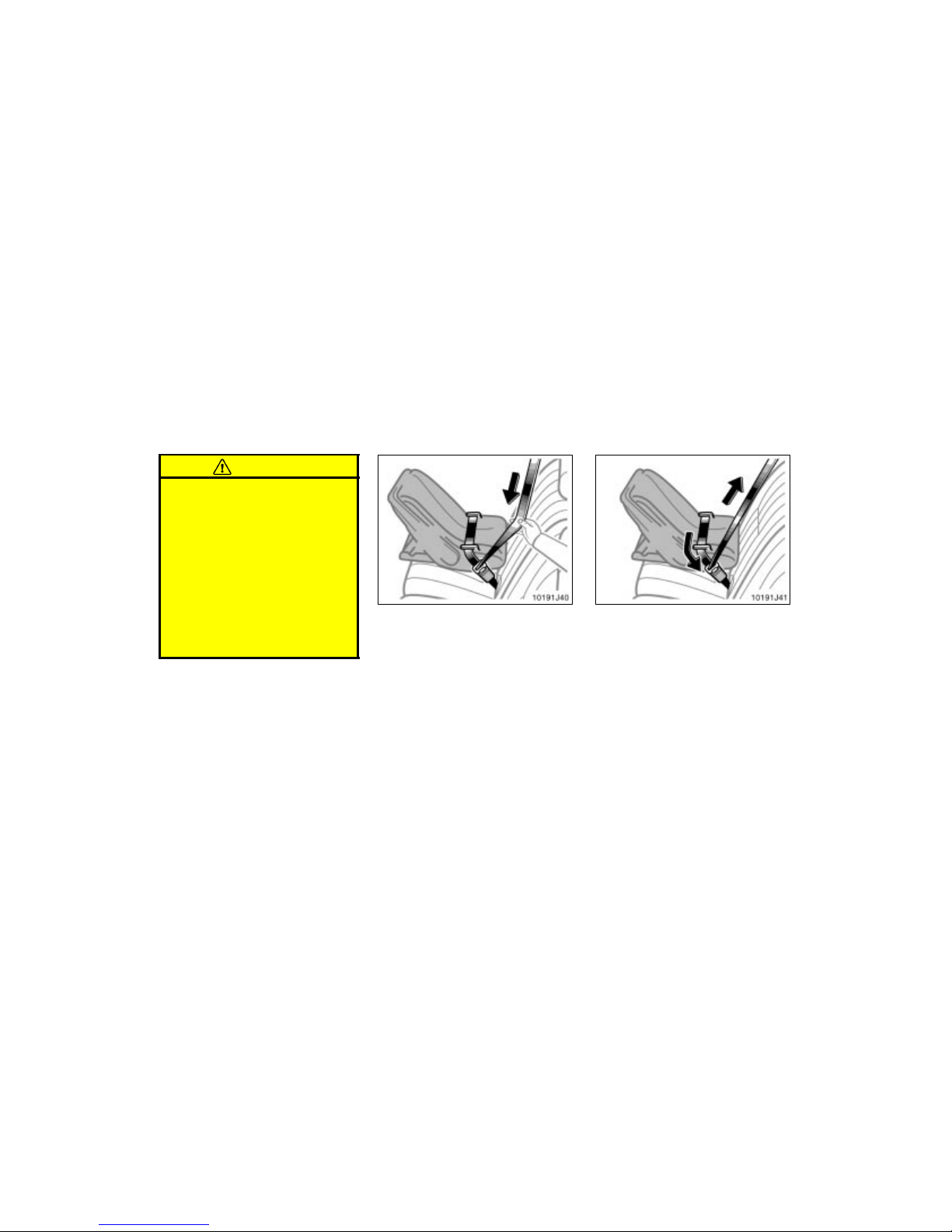
’02 4Runner_U (L/O 0108)
68
2002 MY 4RUNNER_U (OM35787U)
CAUTION
After inserting the tab, make sure
the tab and buckle are locked and
that the lap and shoulder portions
of the belt are not twisted.
Do not insert coins, clips, etc. in
the buckle as this may prevent you
from properly latching the tab and
buckle.
If the seat belt does not function
normally, it cannot protect your
child from injury. Contact your
Toyota dealer immediately. Do not
use the child restraint seat until the
seat belt is fi xed.
2. Fully extend the shoulder belt to put it
in the lock mode. When the belt is
then retracted even slightly, it cannot
be extended.
To hold the infant seat securely, make
sure the belt is in the lock mode before
letting the belt retract.
3. While pressing the infant seat firmly
against the seat cushion and seatback,
let the shoulder belt retract as far as
it will go to hold the infant seat securely.
Page 75
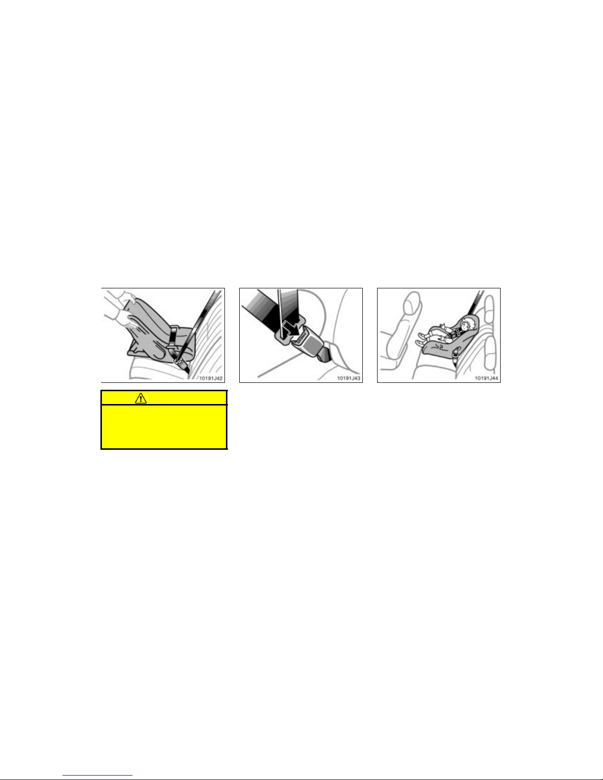
’02 4Runner_U (L/O 0108)
69
2002 MY 4RUNNER_U (OM35787U)
CAUTION
Push and pull the child restraint system in different directions to be sure
it is secure. Follow all the installation
instructions provided by its manufacturer.
4. To remove the infant seat, press the
buckle–release button and allow the
belt to retract completely. The belt will
move freely again and be ready to
work for an adult or older child passenger.
(B) CONVERTIBLE SEAT INSTALLATION
A convertible seat is used in forward–
facing and rear–facing position depending on the child’s age and size. When
installing, follow the manufacturer’s instructions about the applicable child’s
age and size as well as directions for
installing a child restraint system.
Page 76
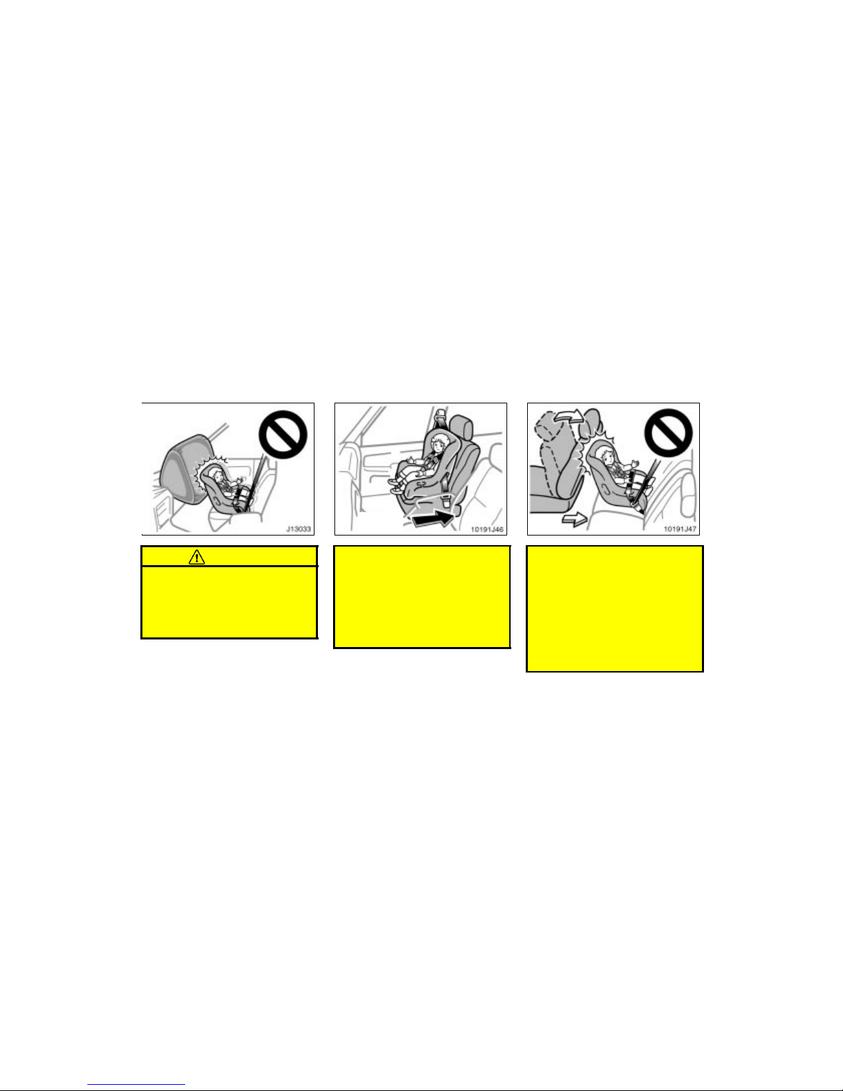
’02 4Runner_U (L/O 0108)
70
2002 MY 4RUNNER_U (OM35787U)
CAUTION
Never install a rear–facing child re-
straint system on the front passenger seat because the force of the
rapid inflation of the front passenger airbag can cause death or serious injury to the child.
Move seat
fully back
A forward–facing chil d restraint sys-
tem should be allowed to be
installed on the front passenger
seat only when it is unavoidable.
Always move the seat as far back
as possible, because the force of
the deploying front passenger airbag could cause death or serious
injury to the child.
Do not install a rear–facing child
restraint system on the rear seat if
it interferes with the lock mechanism of the front seats. This can
cause death or serious injury to the
child and front passenger in case
of sudden braking or a collision.
If the driver’s seat position does
not allow sufficient space for safe
installation, do not install the child
restraint system on the left seat.
Page 77
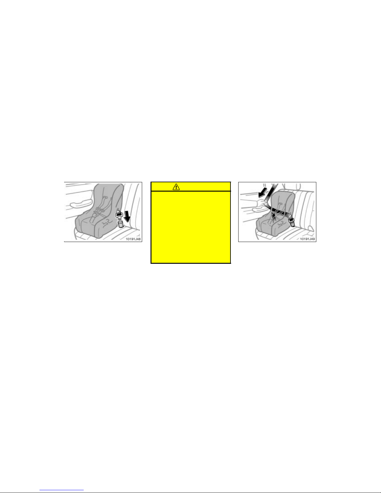
’02 4Runner_U (L/O 0108)
71
2002 MY 4RUNNER_U (OM35787U)
1. Run the lap and shoulder belt through
or around the convertible seat following
the instructions provided by its
manufacturer and insert the tab into
the buckle taking care not to twist the
belt. Keep the lap portion of the belt
tight.
CAUTION
After inserting the tab, make sure
the tab and buckle are locked and
that the lap and shoulder portions
of the belt are not twisted.
Do not insert coins, clips, etc. in
the buckle as this may prevent you
from properly latching the tab and
buckle.
If the seat belt does not function
normally, it cannot protect your
child from injury. Contact your
Toyota dealer immediately. Do not
use the child restraint seat until the
seat belt is fi xed.
2. Fully extend the shoulder belt to put it
in the lock mode. When the belt is
then retracted slightly, it cannot be extended.
To hold the convertible seat securely,
make sure the belt is in the lock mode
before letting the belt retract.
Page 78
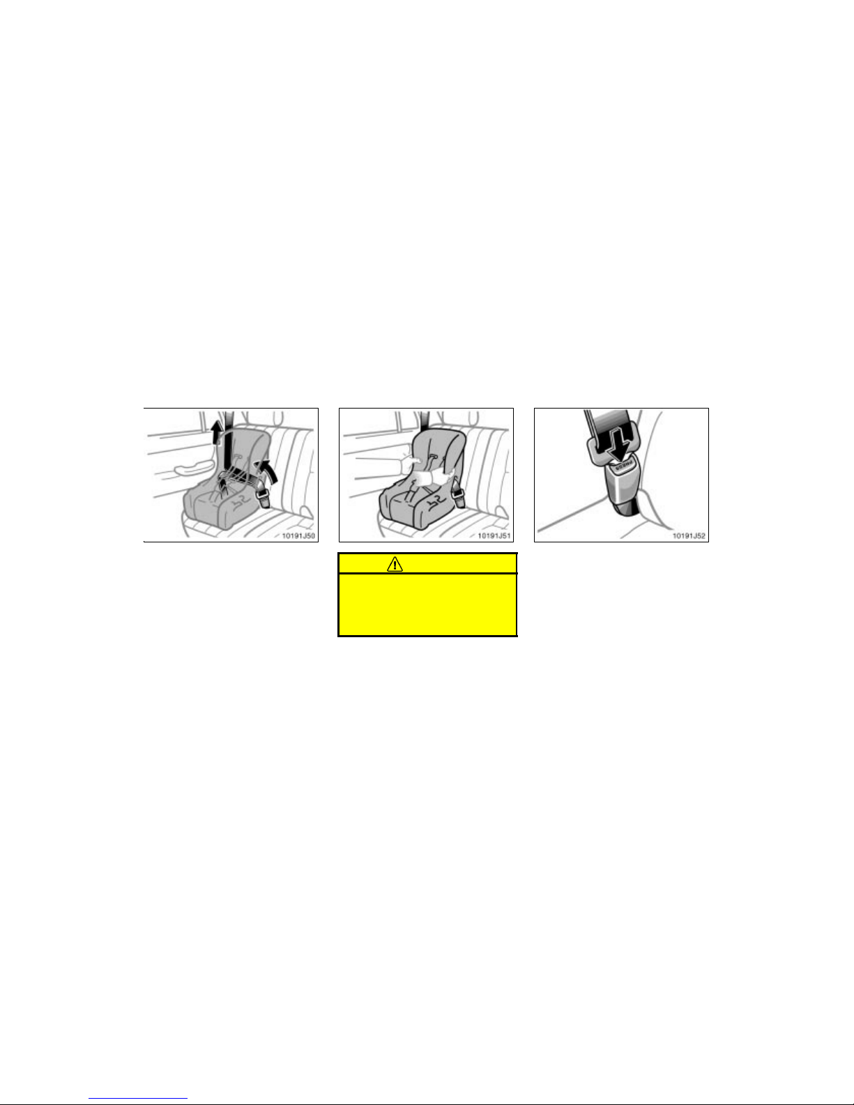
’02 4Runner_U (L/O 0108)
72
2002 MY 4RUNNER_U (OM35787U)
3. While pressing the convertible seat
firmly against the seat cushion and
seatback, let the shoulder belt retract
as far as it will go to hold the convertible seat securely.
CAUTION
Push and pull the child restraint system in different directions to be sure
it is secure. Follow all the installation
instructions provided by its manufacturer.
4. To remove the convertible seat, press
the buckle–release button and allow the
belt to retract completely. The belt will
move freely again and be ready to
work for an adult or older child passenger.
Page 79
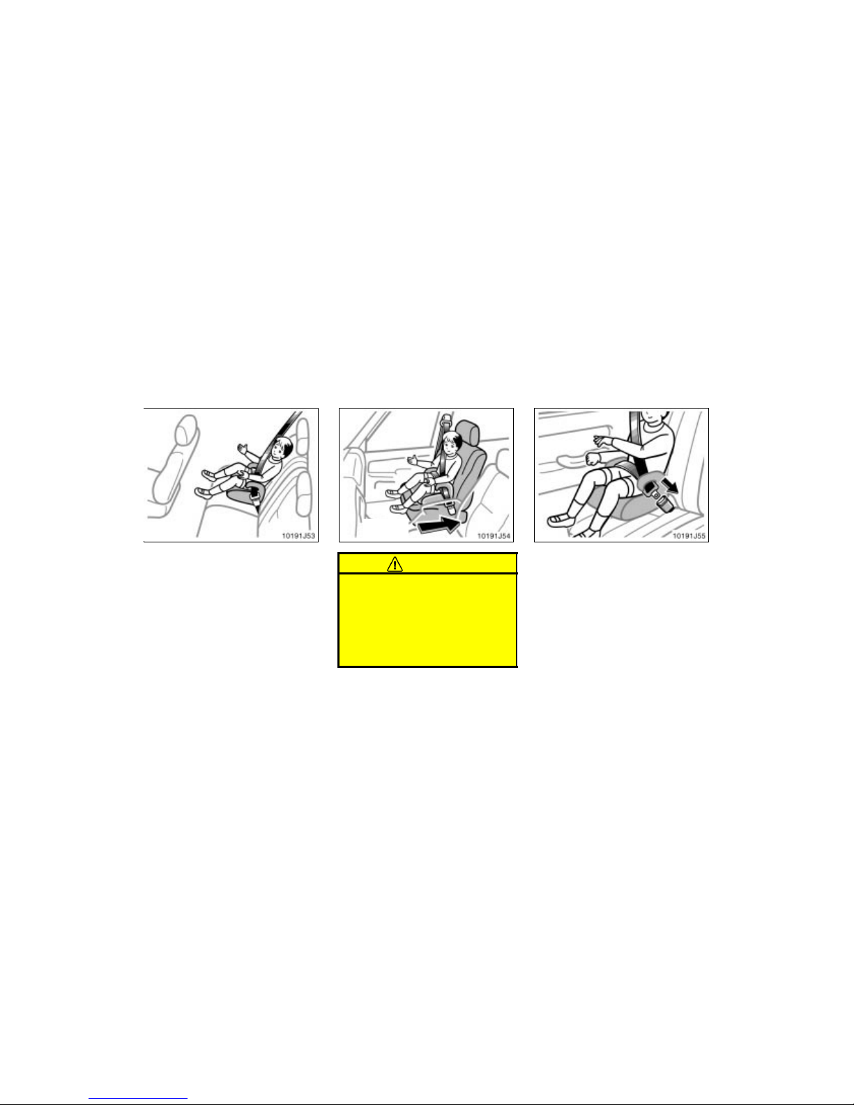
’02 4Runner_U (L/O 0108)
73
2002 MY 4RUNNER_U (OM35787U)
(C) BOOSTER SEAT INSTALLATION
A booster seat is used in forward–fac-
ing position only.
Move seat
fully back
CAUTION
A forward–facing child restraint system should be allowed to be installed
on the front passenger seat only
when it is unavoidable. Always move
the seat as far back as possible, because the force of the deploying front
passenger airbag could cause death
or serious injury to the child.
1. Sit the child on a booster seat. Run
the lap and shoulder belt through or
around the booster seat and child following the instructions provided by its
manufacturer and insert the tab into
the buckle taking care not to twist the
belt.
Make sure the shoulder belt is correctly
across the child’s shoulder and that the
lap belt is positioned as low as possible
on child’s hips. See “Seat belts” for details.
Page 80
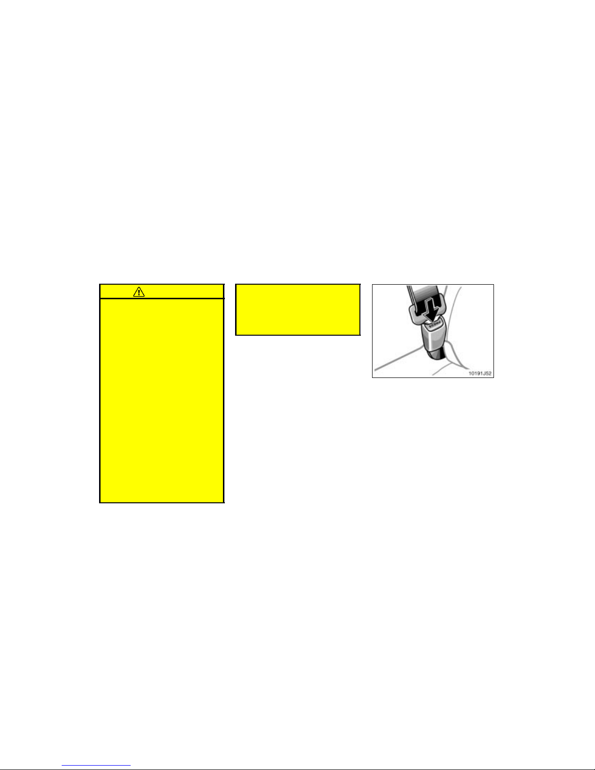
’02 4Runner_U (L/O 0108)
74
2002 MY 4RUNNER_U (OM35787U)
CAUTION
Always make sure the shoulder belt
is positioned across the center of
child’s shoulder. The belt should be
kept away from child’s neck, but
not falling off child’s shoulder. Failure to do so could reduce the
amount of protection in an accident
and cause serious injuries in a collision.
Both high–positioned lap belts and
loose–fitting belts could cause serious injuries due to sliding under
the lap belt during a collision or
other unintended result. Keep the
lap belt positioned as low on a
child’s hips as possible.
For child’s safety, do not place the
shoulder belt under child’s arm.
After inserting the tab, make sure
the tab and buckle are locked and
that the lap and shoulder portions
of the belt are not twisted.
Do not insert coins, clips, etc. in
the buckle as this may prevent your
child from properly latching the tab
and buckle.
If the seat belt does not function
normally, it cannot protect your
child from injury. Contact your
Toyota dealer immediately. Do not
use the child restraint seat until the
seat belt is fi xed.
2. To remove the child restraint system,
press t he buckle–r elease button and allow the belt to retract.
Page 81
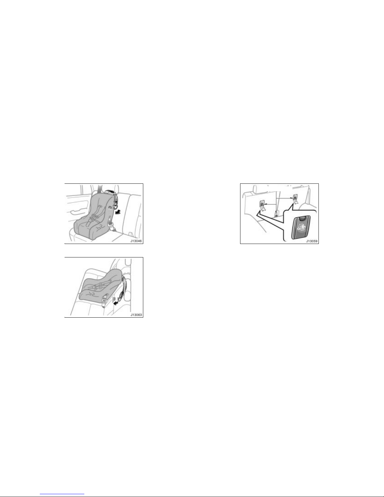
’02 4Runner_U (L/O 0108)
75
2002 MY 4RUNNER_U (OM35787U)
Outside position
Center position
Follow the procedure below for a child
restraint system that requires the use
of a top strap.
Anchor brackets
Symbol
Use the anchor bracket on the back of the
rear seatback to attach the top strap.
Anchor brackets are installed for each
rear seating position.
This symbol indicates the location of user
ready tether anchorage.
—Using a top s trap
Page 82
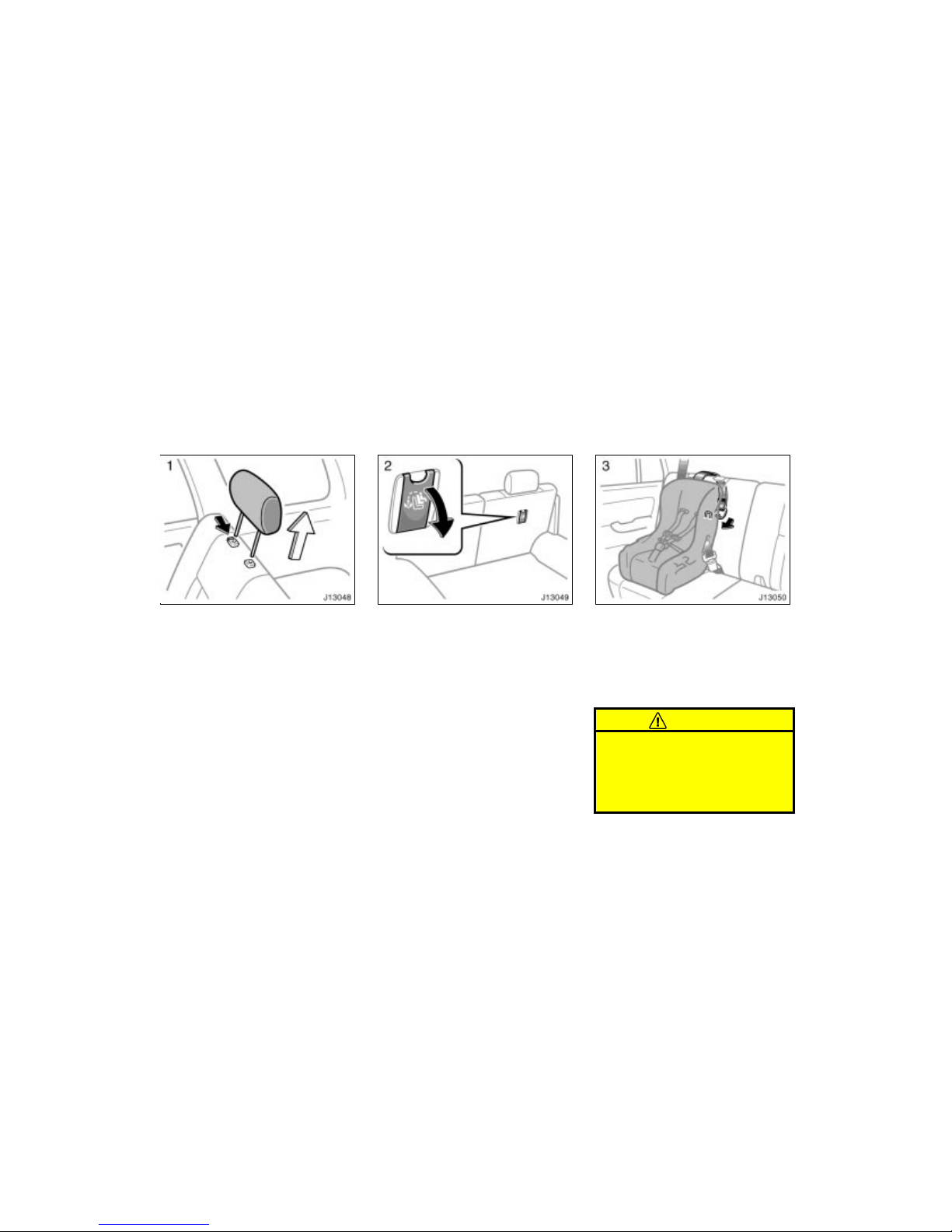
’02 4Runner_U (L/O 0108)
76
2002 MY 4RUNNER_U (OM35787U)
TO USE OUTSIDE ANCHOR BRACKET:
1. Remove the head restraint.
2. Open the anchor bracket cover with
the symbol mark shown in the illustration.
3. Fix the child restraint system with
the seat belt.
Latch the hook onto the anchor
bracket and tighten the top strap.
For instructions to install the child restraint system, see “Child restraint” in this
section.
CAUTION
Make sure the top strap is securely
latched, and check that the child restraint system is secure by pushing
and pulling it in different directions.
Follow all the installation instructions
provided by its manufacturer.
Page 83
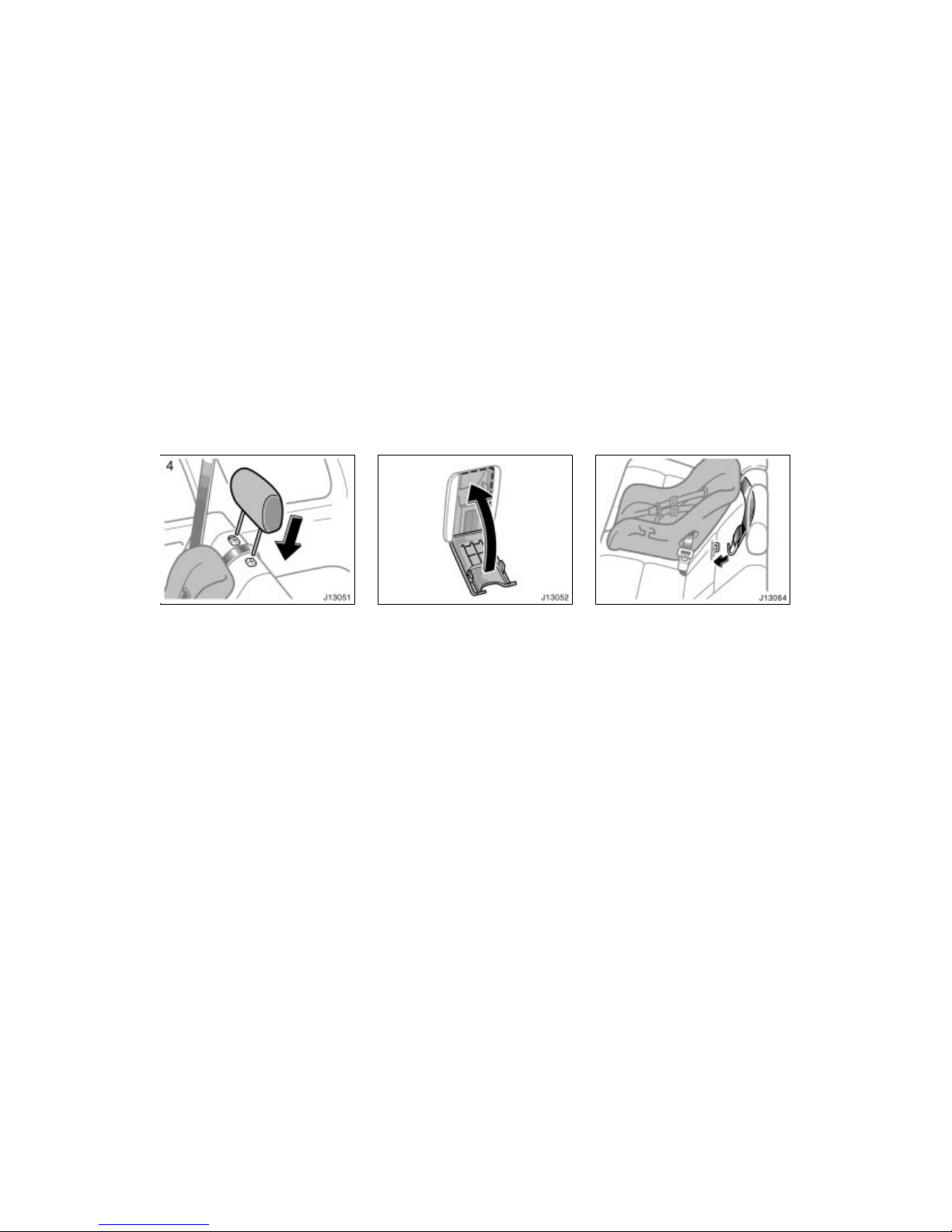
’02 4Runner_U (L/O 0108)
77
2002 MY 4RUNNER_U (OM35787U)
4. Replace the head restraint. Be sure to close all covers when the anchor bracket is not in use.
TO USE CENTER ANCHOR BRACKET:
Fix the child restraint system with the
seat belt. Run the top strap through
between both seatbacks.
Latch the hook onto the anchor bracket
and tighten the top strap.
For instructions to install the child restraint system, see “Child restraint” in this
section.
Page 84
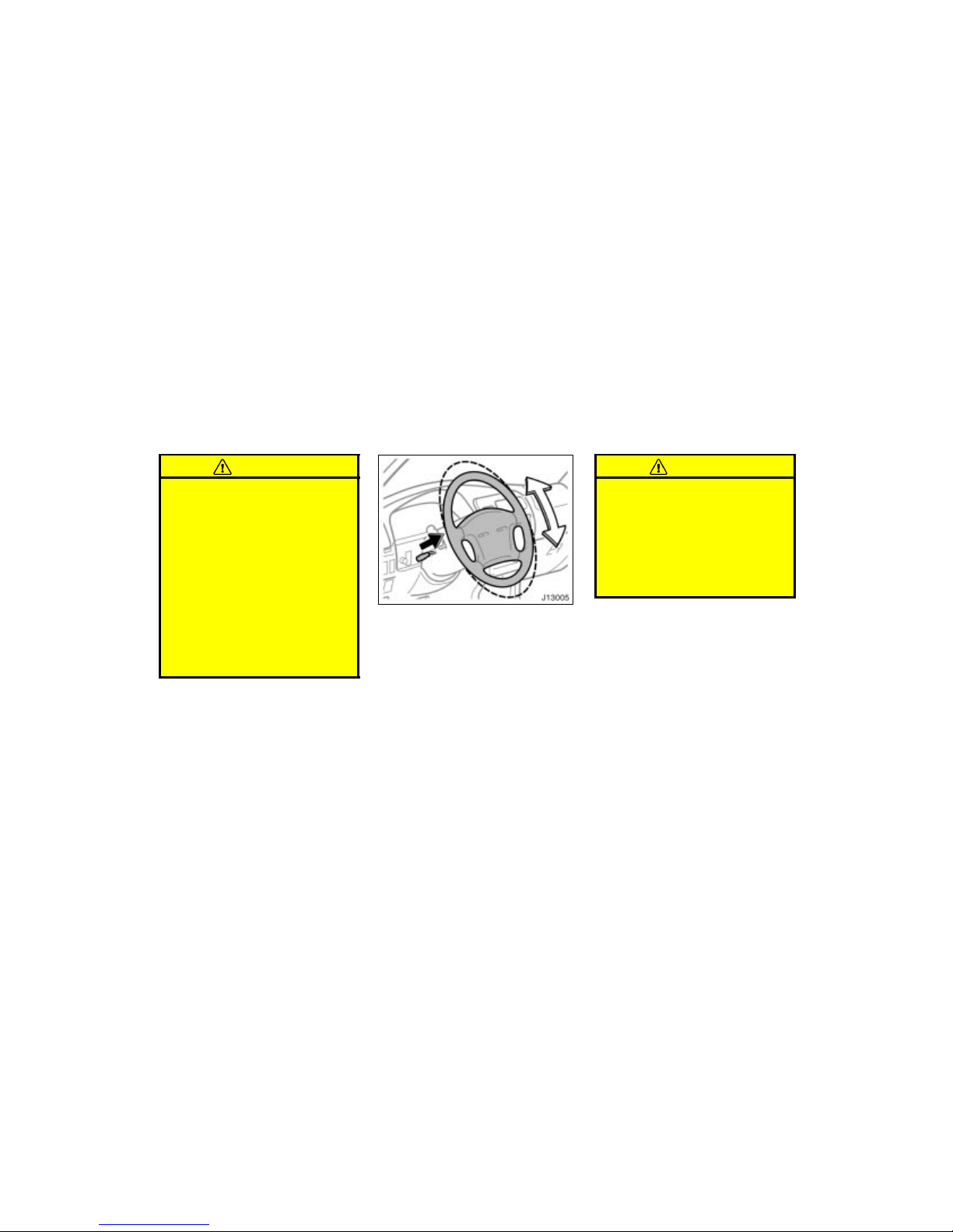
’02 4Runner_U (L/O 0108)
78
2002 MY 4RUNNER_U (OM35787U)
CAUTION
When you use the center anchor
bracket, make sure the top strap
runs through between both seatbacks and tighten it. The top strap
on seatback could cause death or
serious injury due to abnormal
moving of the child rest raint system
in case of sudden braking or a collision.
Make sure the top strap is securely
latched, and check that the child
restraint system is secure by pushing and pulling it in different directions. Follow all the installation instructions provided by its manufacturer.
To change the steering wheel angle,
hold the steering wheel, pull the lock
release lever toward you, tilt the steering wheel to the desired angle and return the lever to its original position.
When the steering wheel is in a low position, it will spring up as you release the
lock release lever.
CAUTION
Do not adjust the steering wheel
while the vehicle is moving. It may
cause the driver to mishandle the
vehicle and an accident may occur
resulting in death or serious injuries.
After adjusting the steering wheel,
try moving it up and down to make
sure it is locked in position.
Tilt steering wheel
Page 85
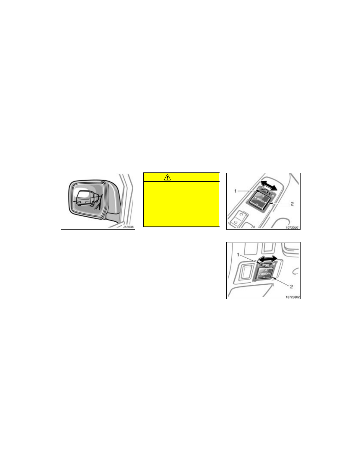
’02 4Runner_U (L/O 0108)
79
2002 MY 4RUNNER_U (OM35787U)
Adjust the mirror so that you can see
the side of your vehicle in the mirror.
Be careful when judging the size or distance of any object seen in the outside
rear view mirror on the passenger’s side.
It is a convex mirror with a curved surface. Any object seen in a convex mirror
will look smaller and farther away than
when seen in a flat mirror.
On some models, when you push the
back window defogger switch, the heater
panels in the outside rear view mirrors will
quickly clear the surface. To turn on the
back window defogger, see “Back window
and outside rear view mirror defoggers” in
Section 1–4.
CAUTION
Do not adjust the mirror while the
vehicle is moving. It may cause the
driver to mishandle the vehicle and
an accident may occur resulting in
death or serious injuries.
On some models, since the mirror
surfaces can get hot, keep your
hands off them when the defogger
switch is on.
With power windows (door armrest)
Without power windows
(instrument panel)
Outside rear view mirrors—
—Power Rear view mirror
control
Page 86
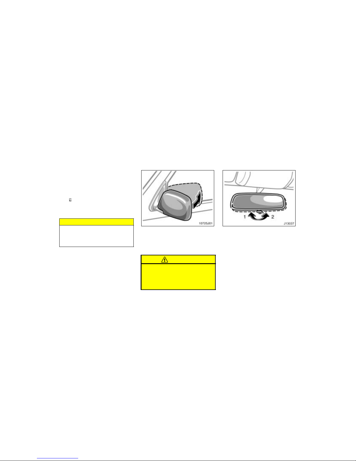
’02 4Runner_U (L/O 0108)
80
2002 MY 4RUNNER_U (OM35787U)
To adjust a mirror, use the switches.
1. Master switch—To select the mirror to
be adjusted
Place the switch at “L” (left) or “R”
(right).
2. Control switch—To move the mir-
ror
Push the switch in the desired
direction.
Mirror can be adjusted when key is in the
“ACC” or “ON” position.
NOTICE
If ice should jam the mirror, do not
operate the control or scrape the mirror face. Use a spray de–icer to free
the mirror.
The rear view mirrors can be folded
backward for parking in restricted
areas.
To fold the rear view mirror, push backward.
CAUTION
Do not drive with the mirrors folded
backward. Both the driver and passenger side rear view mirrors must
be extended and properly adjusted
before driving.
Adjust the mirror so that you can just
see the rear of your vehicle in the mirror.
To reduce glare from the headlights of
the vehicle behind you during night
driving, operate the lever on the lower
edge of the mirror.
Daylight driving—Lever at position 1
The reflection in the mirror has greater
clarity at this position.
Night driving—Lever at position 2
Remember that b y reducing glare you also
lose some rear view clarity.
—Folding rear view mirrors
Anti–glare inside rear view
mirror
Page 87
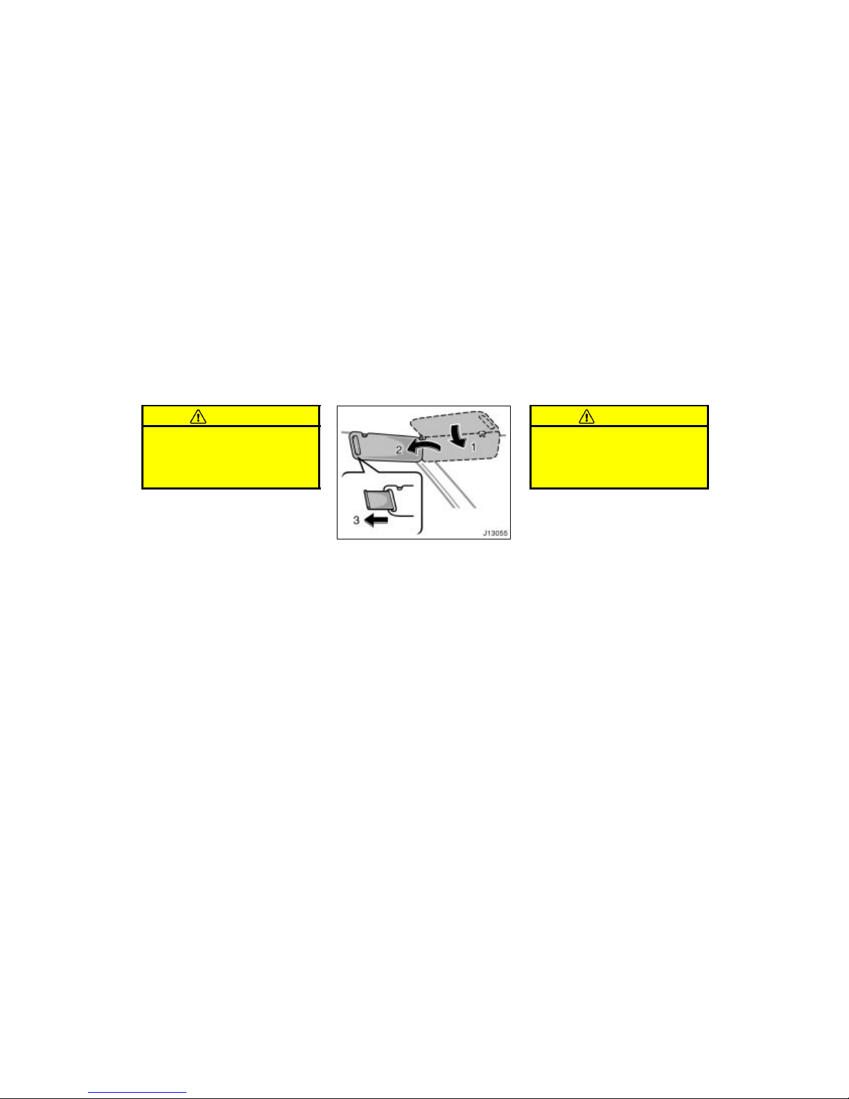
’02 4Runner_U (L/O 0108)
81
2002 MY 4RUNNER_U (OM35787U)
CAUTION
Do not adjust the mirror while the
vehicle is moving. It may cause the
driver to mishandle the vehicle and
an accident may occur resulting in
death or serious injuries.
To block out glare, move the sun visor.
To block out glare from the front—Swing
down the sun visor (position 1).
To block out glare from the side—Swing
down the sun visor, remove it from the
hook and swing it t o the lateral side (position 2).
If glare comes from obliquely behind you,
extend the plate at the end of the visor
(to position 3).
CAUTION
Do not extend the plate at the end of
the sun visor when the visor is in the
position 1. It can cover the anti–glare
inside rear view mirror and obstruct
the rear view.
Sun visors—
Page 88
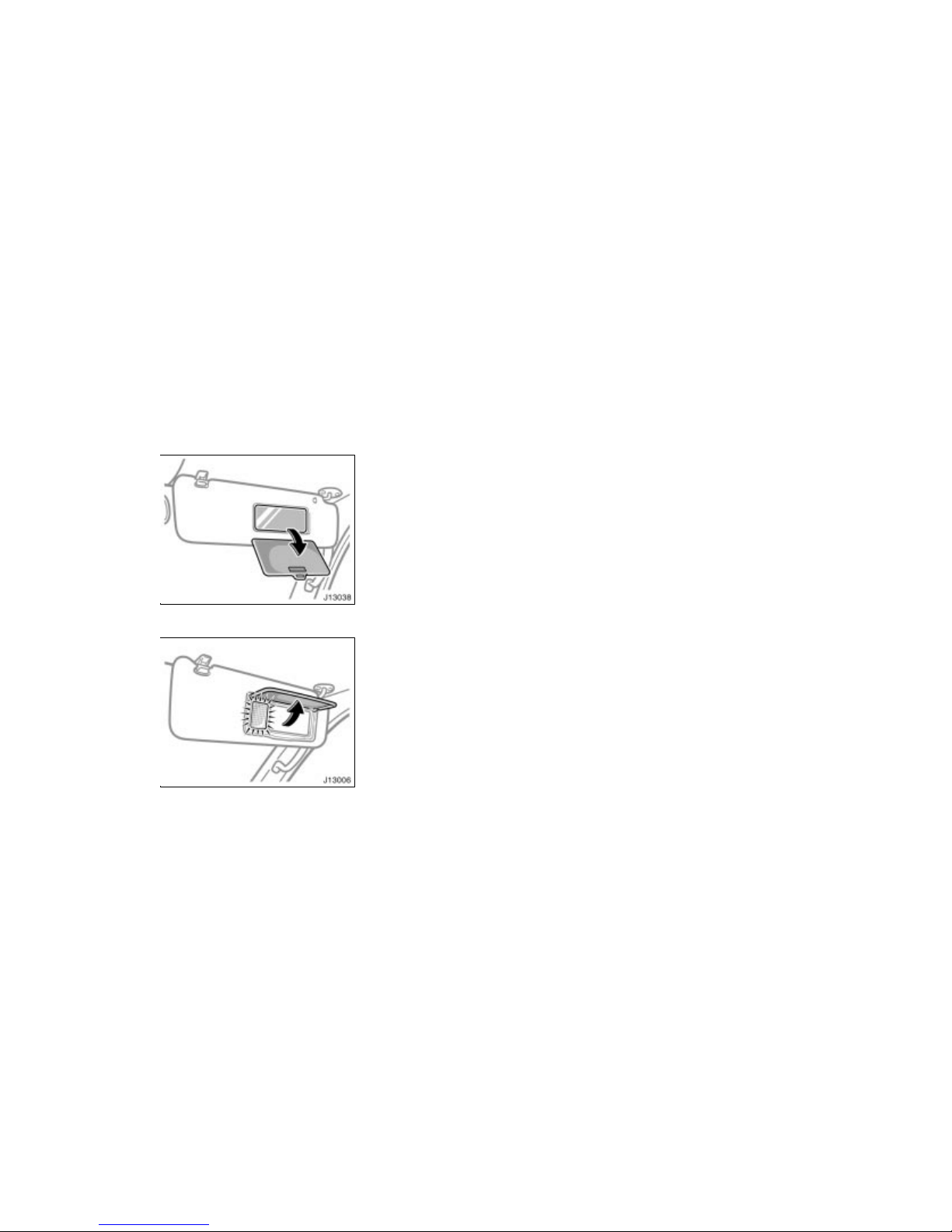
’02 4Runner_U (L/O 0108)
82
2002 MY 4RUNNER_U (OM35787U)
Type A
Type B
To use the vanity mirrors, swing down
the sun visor and open the cover.
Type B only—The vanity light comes on
when you open the cover.
—Vanity mirrors
Page 89
’02 4Runner_U (L/O 0108)
83
2002 MY 4RUNNER_U (OM35787U)
OPERATION O F INSTRUMENTS AND
CONTROLS
Lights, Wipers and Defogger
Headlights and turn signals 84. . . . . . . . . . . . . . . . . . . . . . . . . . . . . . . . . . .
Emergency flashers 85. . . . . . . . . . . . . . . . . . . . . . . . . . . . . . . . . . . . . . . . . .
Instrument p anel light c ontrol 86. . . . . . . . . . . . . . . . . . . . . . . . . . . . . . . . .
Front fog lights 86. . . . . . . . . . . . . . . . . . . . . . . . . . . . . . . . . . . . . . . . . . . . . .
Interior l i ght 86. . . . . . . . . . . . . . . . . . . . . . . . . . . . . . . . . . . . . . . . . . . . . . . . .
Personal lights 87. . . . . . . . . . . . . . . . . . . . . . . . . . . . . . . . . . . . . . . . . . . . . .
Luggage compartment light 87. . . . . . . . . . . . . . . . . . . . . . . . . . . . . . . . . . .
Ignition switch light 88. . . . . . . . . . . . . . . . . . . . . . . . . . . . . . . . . . . . . . . . . .
Windshield wipers and washer 88. . . . . . . . . . . . . . . . . . . . . . . . . . . . . . . .
Back window wiper and washer 89. . . . . . . . . . . . . . . . . . . . . . . . . . . . . . .
Back window and outside rear view mirror defogger s 90. . . . . . . . . . . .
SECTION 1–
4
Page 90
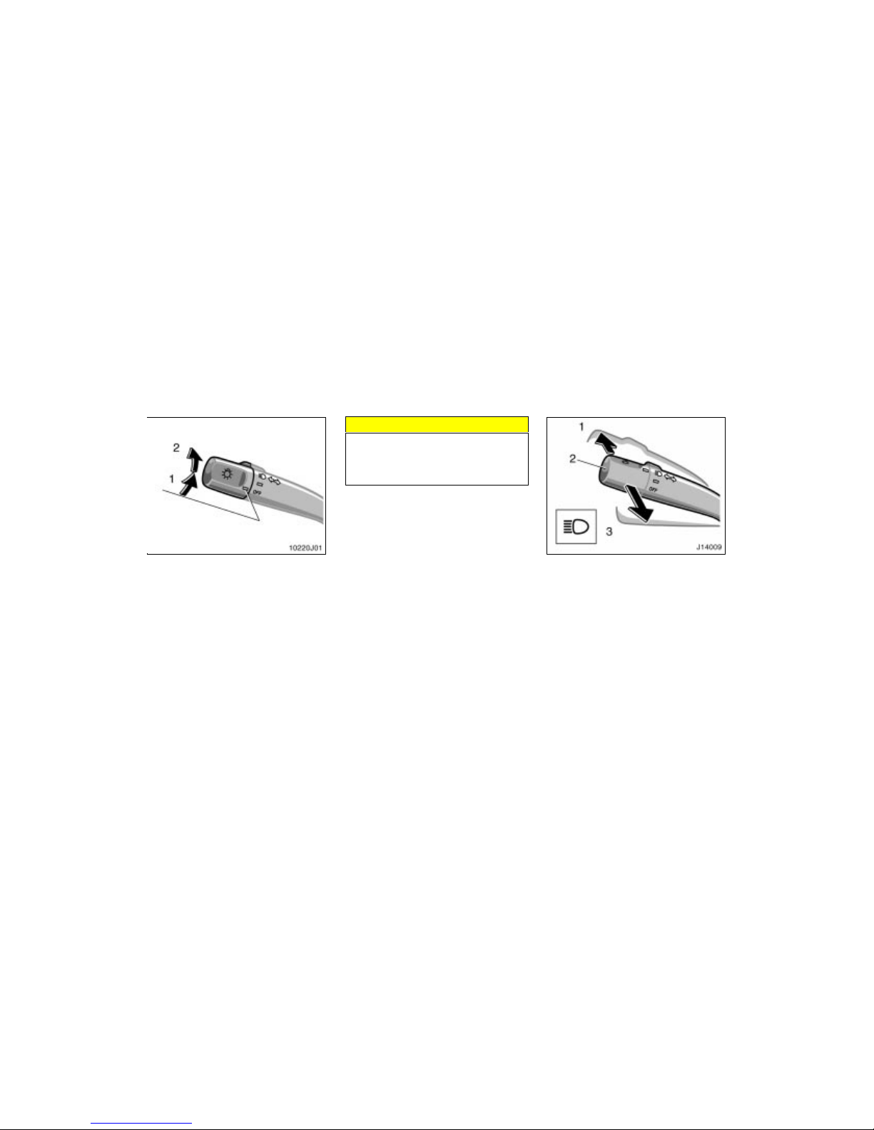
’02 4Runner_U (L/O 0108)
84
2002 MY 4RUNNER_U (OM35787U)
HEADLIGHTS
To turn on the following lights: Twist
the headlight/turn signal lever knob.
Position 1—Parking, tail, license plate,
side marker and instrument panel lights
Position 2—Headlights and all of the
above
The lights automatically turn off when the
driver’s door is opened with the ignition
switch turned off. To turn them on again,
turn the key to the “ON” position or actuate the headlight switch. If you are going
to park for over one week, make sure the
headlight switch is off.
NOTICE
To prevent the batter y from being discharged, do not leave the lights on
for a long period when the engine is
not running.
Daytime running light system (on some
models)
The headlights turn on when the parking
brake is released with the engine started,
even with the light switch in the “OFF”
position. They will not go off until the
ignition switch is turned off.
To turn on the other exterior lights and
instrument panel lights, twist the knob to
the position 1.
Under the daytime running light system,
the headlights turn on at reduc ed intensi ty.
Twist the knob to the position 2 to turn
to full intensity for driving at night.
High–Low beams—For high beams, turn
the headlights on and push the lever away
from you (position 1). Pull the lever toward you (position 2) for low beams.
The headlight high beam indicator light
(blue light) on the instrument panel will
tell you that the high beams are on.
Flashing the high beam headlights
(position 3)—Pull the lever all the way
back. The high beam headlights turn off
when you release the lever.
You can flash the high beam headlights
with the knob turned to “OFF”.
Headlights and turn signals
Page 91
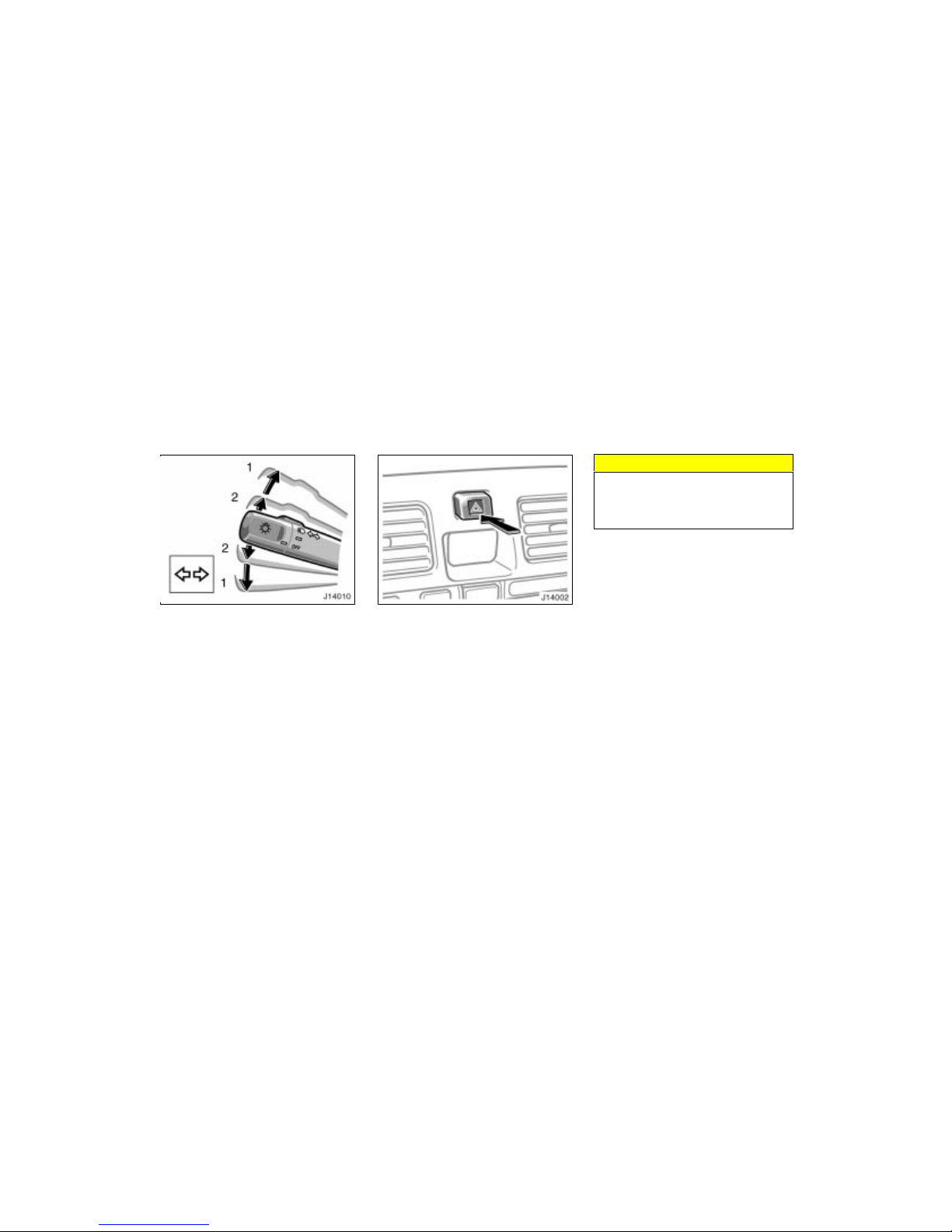
’02 4Runner_U (L/O 0108)
85
2002 MY 4RUNNER_U (OM35787U)
TURN SIGNALS
To signal a turn, push the headlight/
turn signal lever up or down to positi on
1.
The key must be in the “ON” position.
The lever automatically returns after you
make a turn, but you may have to return
it by hand after you change lanes.
To signal a lane change, move the lever
up or down to the pressure point (position
2) and hold it.
If the turn signal indicator lights (green
lights) on the instrument panel flash faster
than normal, a front or rear turn signal
bulb is burned out.
To turn on the emergency flashers,
push the switch.
All the turn signal lights will flash. To turn
them off, push the switch once again.
Turn on the emergency flashers to warn
other drivers if your vehicle must be
stopped where it mi ght be a traffic hazard.
Always pull as far off the road as possible.
The turn signal light switch will not work
when the emergency flashers are operating.
NOTICE
To prevent the batter y from being discharged, do not leave the switch on
longer than necessary when the engine is not running.
Emergency flashers
Page 92
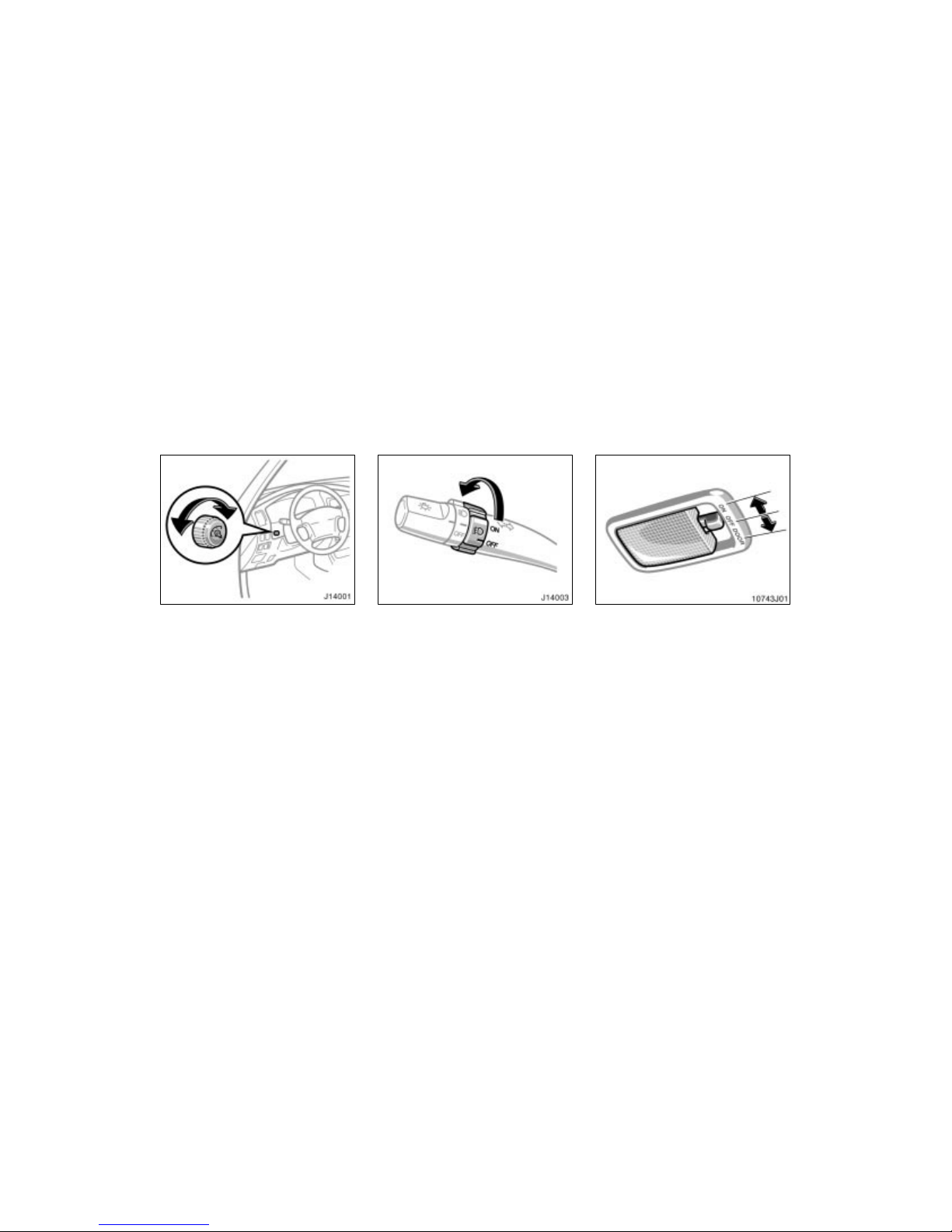
’02 4Runner_U (L/O 0108)
86
2002 MY 4RUNNER_U (OM35787U)
To adjust the brightness of the instrument panel lights, turn the knob.
To turn on the front fog lights, twist
the band of the headlight and turn signal switch lever. They will come on
only when the headlights are on low
beam.
To turn on the interior light, slide the
switch.
The interior light switch has the following
positions:
“ON”—Keeps the light on all the time.
“OFF”—Turns the light off.
“DOOR”—Turns the light on when any of
the side door is opened. The light goes
off when all the side doors are closed.
Instrument panel light control Front fog lights Interior light
Page 93
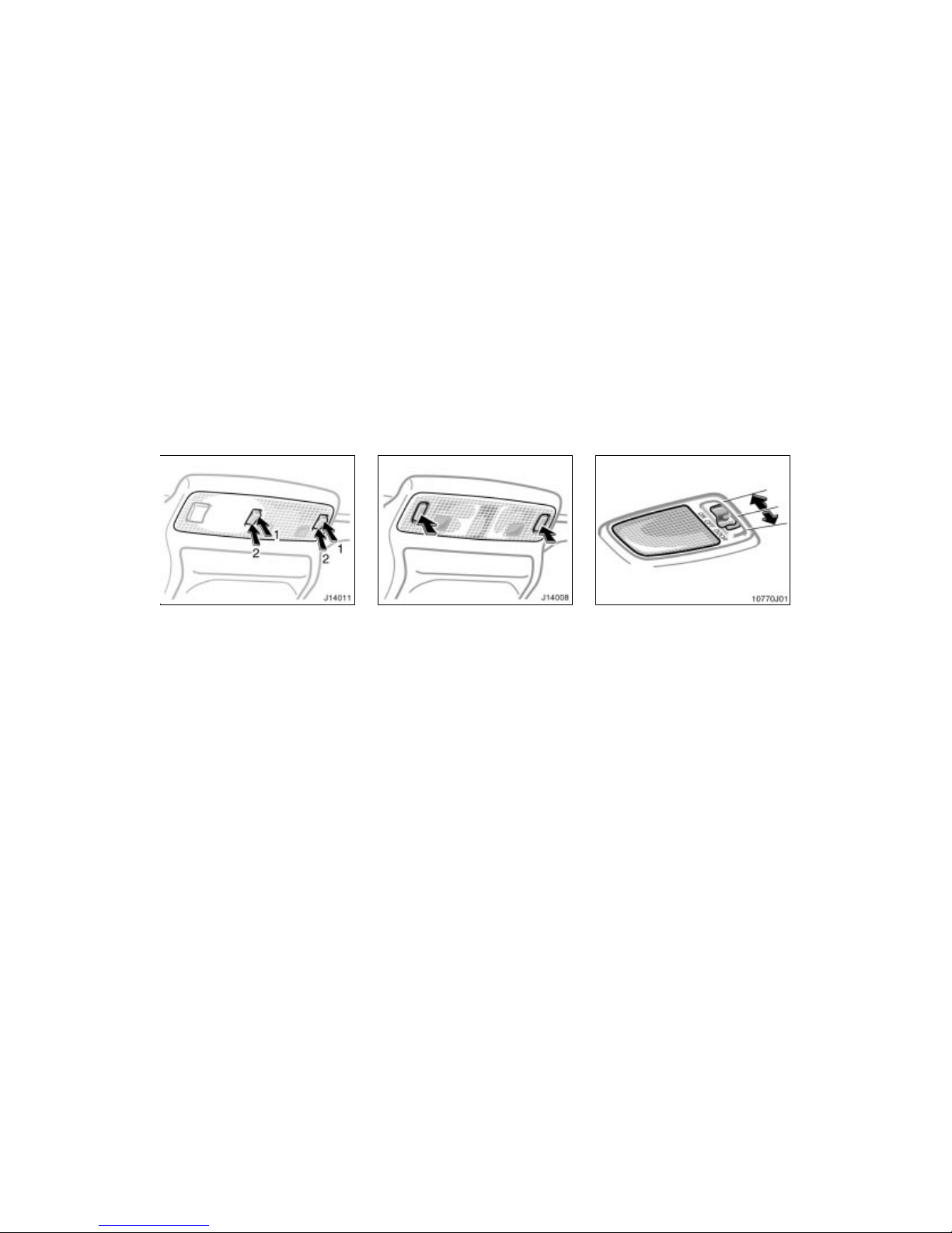
’02 4Runner_U (L/O 0108)
87
2002 MY 4RUNNER_U (OM35787U)
To turn on the personal light, push the
switch on 1 side. To turn the light off,
push the switch on 2 side.
To turn on the personal light, push the
switch. To turn the lights off, push the
switch once again.
To turn on the luggage compartment
light, slide the switch.
The luggage compartment light switch has
the following positions:
“ON”—Keeps the light on all the time.
“OFF”—Turns the light off.
“DOOR”—Turns the light on when the
back door is opened. The light goes off
when the back door is closed.
Personal lights
(with moon roof)
Personal lights
(without moon roof)
Luggage compartment light
Page 94
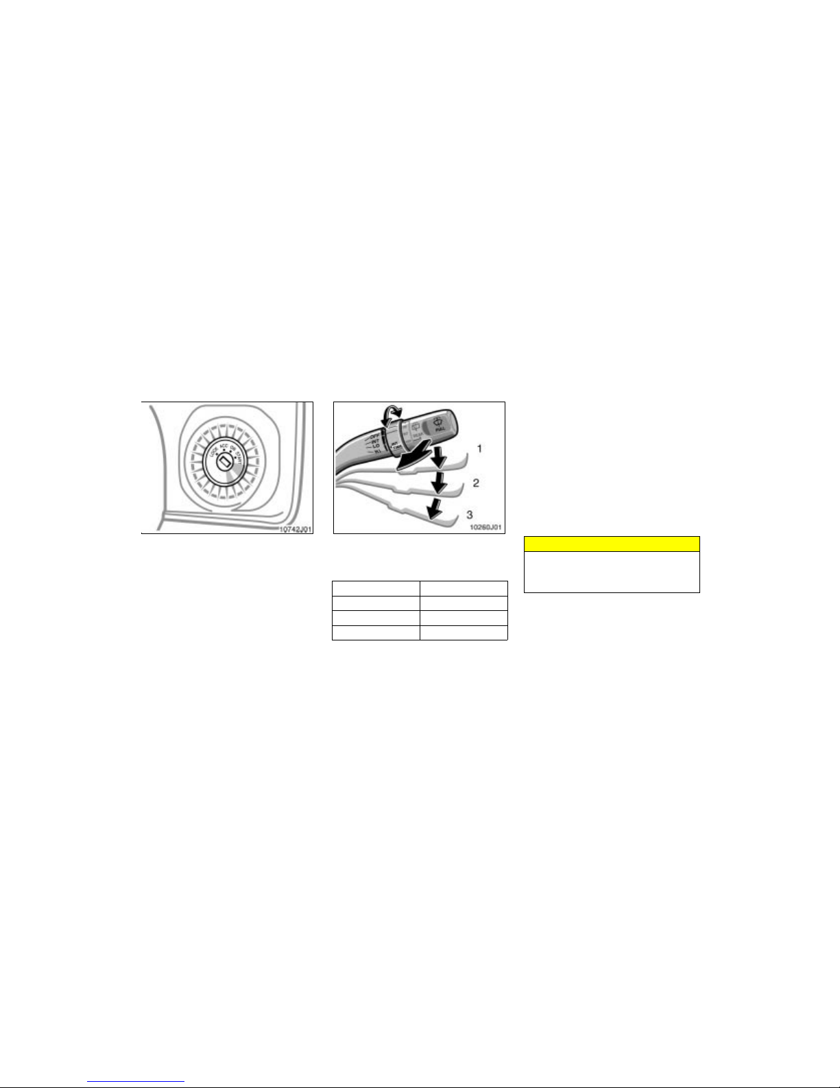
’02 4Runner_U (L/O 0108)
88
2002 MY 4RUNNER_U (OM35787U)
For easy access to the ignition switch,
the ignition switch light comes on when
the driver’s door is opened.
The light remains on for some time after
driver’s door is closed.
To turn on the windshield wipers, move
the lever to the desired setting.
The key must be in the “ON” position.
Lever position Speed setting
Position 1 Intermittent
Position 2 Slow
Position 3 Fast
The “INT TIME” band lets you adjust the
wiping time interval when the wiper lever
is in the intermittent position (position 1).
Twist the band upward to increase the
time between sweeps, and downward to
decrease it.
To squirt washer fluid, pull the lever
toward you.
If the windshield wipers are off, they will
operate a couple of times after the washer
squirts .
For instructions on adding washer fluid,
see “Adding washer fluid” in Section 7–3.
In freezing weather, warm the windshield
with the defroster before using the washer.
This will help prevent the washer fluid
from freezing on your windshield, which
can block your vision.
NOTICE
Do not operate the wipers if the windshield is dry. It may scratch the
glass.
Ignition switch light
Windshield wipers and washer
(intermittent type)
Page 95
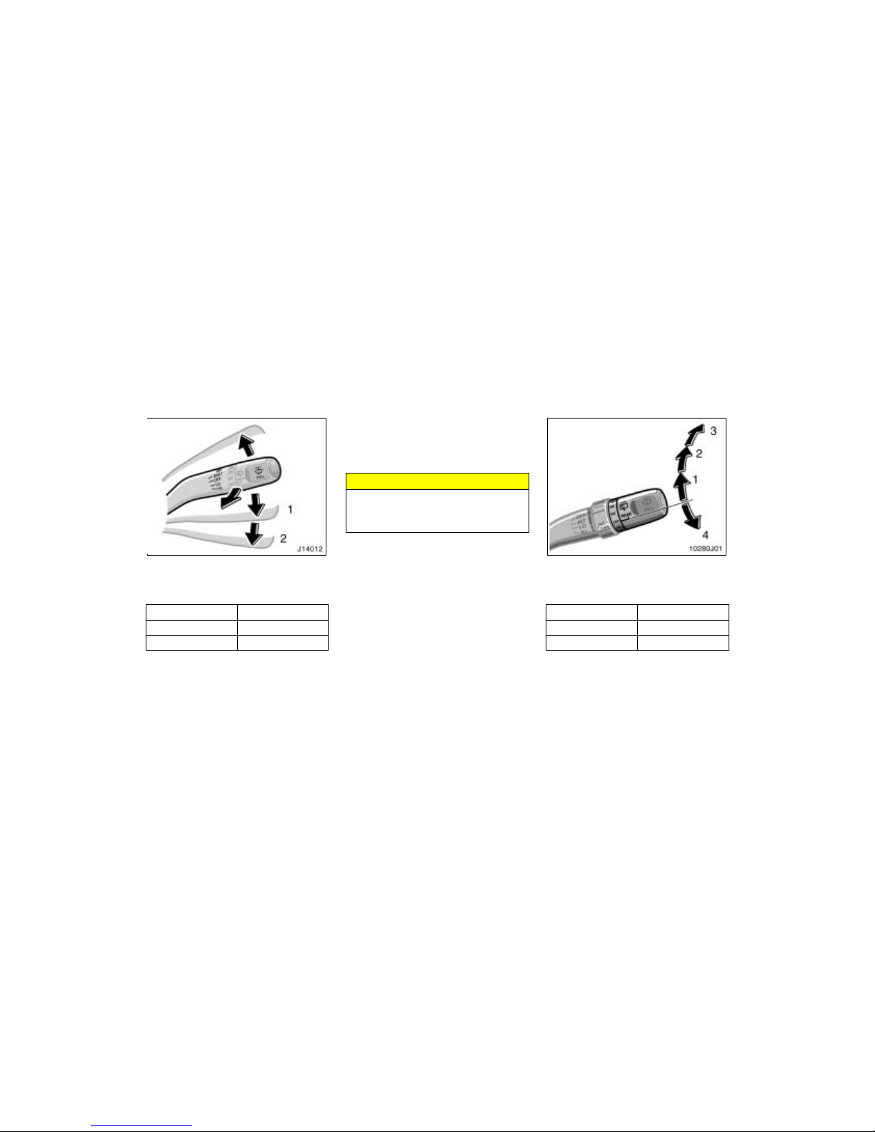
’02 4Runner_U (L/O 0108)
89
2002 MY 4RUNNER_U (OM35787U)
To turn on the windshield wipers, move
the lever to the desired setting.
The key must be in the “ON” position.
Lever position Speed setting
Position 1 Slow
Position 2 Fast
For a single sweep of the windshield,
push the lever up and release it.
To squirt washer fluid, pull the lever
toward you.
For instructions on adding washer fluid,
see “Adding washer fluid” in Section 7–3.
In freezing weather, warm the windshield
with the defroster before using the washer.
This will help prevent the washer fluid
from freezing on your windshield, which
can block your vision.
NOTICE
Do not operate the wipers if the windshield is dry. It may scratch the
glass.
To turn on the back window wiper, twist
the lever knob upward.
The key must be in the “ON” position.
Lever position Speed setting
Position 1 Intermittent
Position 2 Normal
To squirt washer fluid on the bac k window,
twist the knob upward or downward as far
as it will go (position 3 or 4). The knob
automatically returns from these positions
after you release it.
For instructions on adding washer fluid,
see “Adding washer fluid” in Section 7–3.
Windshield wipers and washer
(mist type)
Back window wiper and
washer
Page 96
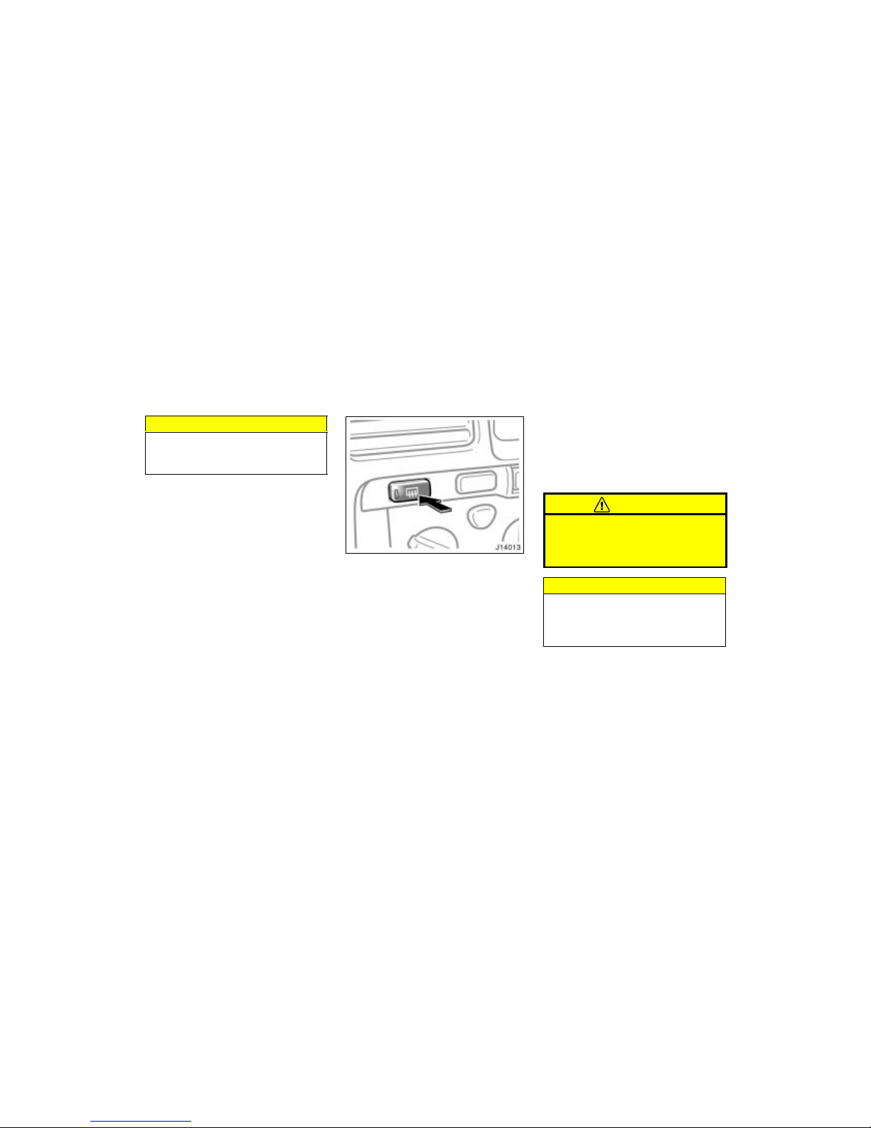
’02 4Runner_U (L/O 0108)
90
2002 MY 4RUNNER_U (OM35787U)
NOTICE
Do not operate the back window wiper if the back window is dry. It may
scratch the glass.
To defog or defrost the back window,
push the switch with the back window
closed.
The key must be in the “ON” position.
The thin heater wires on the inside of the
back window wil l quickly clear t he surface.
An indicator light will illuminate to indicate
the defogger is operating.
On some models, heater panels in the
outside rear view mirrors will also quickly
clear the surfaces.
Push the switch once again to turn the
defogger off.
The system will automatically shut off after the defoggers have operated about 15
minutes.
Make sure you turn the defoggers off
when the surfaces are clear. Leaving the
defoggers on for a long time could cause
the battery to discharge, especially during
stop–and–go driving. The defoggers are
not designed for drying rain water or for
melting snow.
CAUTION
On some models, since the mirror
surfaces can get hot, keep your
hands off them when the defogger
switch is on.
NOTICE
When cleaning the inside of the back
window, be careful not to scratch or
damage the heater wires or connectors.
Back window and outside rear
view mirror defoggers
Page 97
’02 4Runner_U (L/O 0108)
91
2002 MY 4RUNNER_U (OM35787U)
OPERATION O F INSTRUMENTS AND
CONTROLS
Gauges, Meters and Service reminder indicators
Fuel gauge 92. . . . . . . . . . . . . . . . . . . . . . . . . . . . . . . . . . . . . . . . . . . . . . . . .
Engine coolant temperature gauge 92. . . . . . . . . . . . . . . . . . . . . . . . . . . .
Tachometer 93. . . . . . . . . . . . . . . . . . . . . . . . . . . . . . . . . . . . . . . . . . . . . . . . .
Odometer and two tri p meters 93. . . . . . . . . . . . . . . . . . . . . . . . . . . . . . . . .
Service reminder indicators and warning buzzers 94. . . . . . . . . . . . . . .
SECTION 1–
5
Page 98
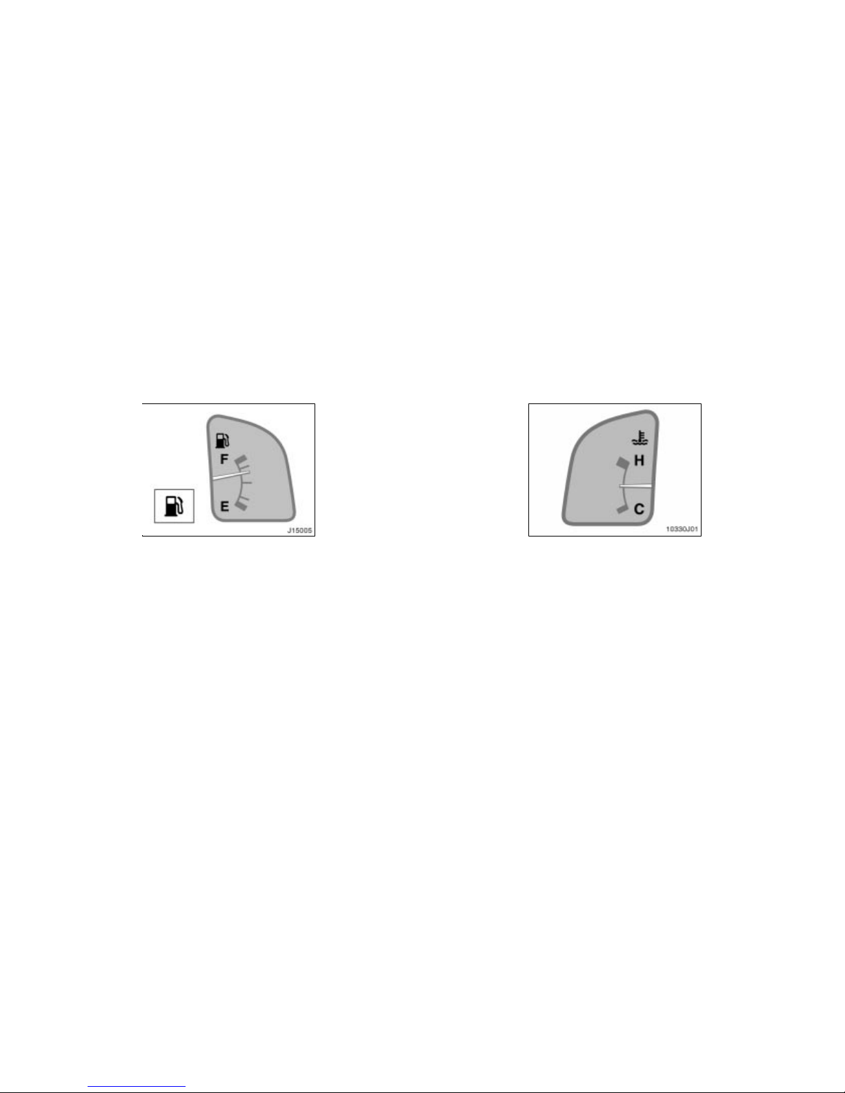
’02 4Runner_U (L/O 0108)
92
2002 MY 4RUNNER_U (OM35787U)
The gauge works when the ignition
switch is on and indicates the approximate quantity of fuel remaining in the
tank.
Nearly full—Needle at “F”
Nearly empty—Needle at “E”
It is a good idea to keep the tank over
1/4 full.
If the fuel level approaches “E” or the low
fuel level warning light comes on, fill the
fuel tank as soon as possible.
On inclines or curves, due to the movement of fuel in the tank, the fuel gauge
needle may fluctuate or the low fuel level
warning light may come on earlier than
usual.
If the fuel tank is completely empty, the
malfunction indicator lamp comes on. Fill
the fuel tank immediately.
The indicator lamp goes off after driving
several times. If the indicator lamp does
not go off, contact your Toyota dealer as
soon as possible.
The gauge indicates the engine coolant
temperature when the ignition switch is
on. The engine operating temperature
will vary with changes in weather and
engine load.
If the needle moves into the red zone,
your engine is too hot. If your vehicle
overheats, stop your vehic le and allow the
engine to cool.
Your vehicle may overheat during severe
operating conditions, such as:
Driving up a long hill on a hot day.
Reducing speed or stopping after high
speed driving.
Fuel gauge
Engine coolant temperature
gauge
Page 99
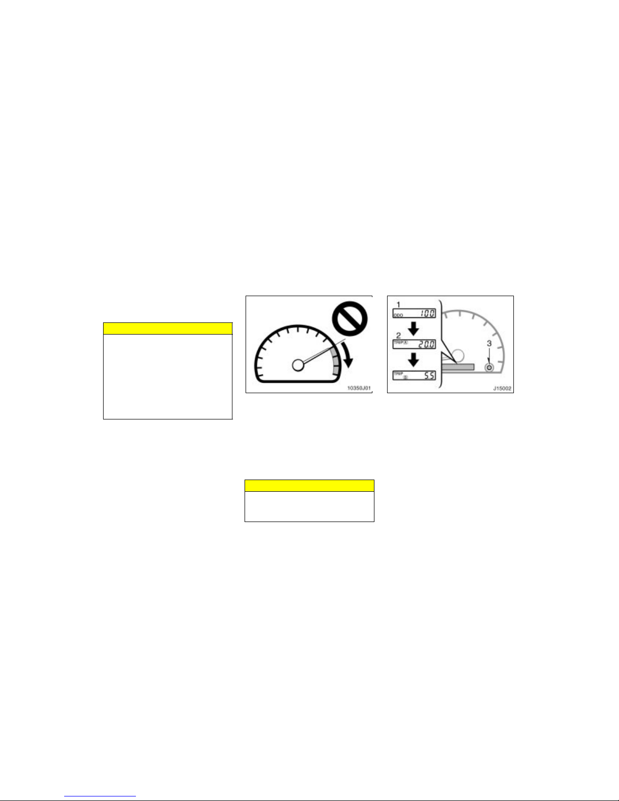
’02 4Runner_U (L/O 0108)
93
2002 MY 4RUNNER_U (OM35787U)
Idling for a long period with the air
conditioning on in stop–and–go traffic.
Towing a trailer.
NOTICE
Do not remove the thermostat in
the engine cooling system as this
may cause the engine to overheat.
The thermostat is designed to control the flow of coolant to keep the
temperature of the engine within
the specified operating range.
Do not continue driving with an
overheated engine. See “If your vehicle overheats” in Section 4.
The tachometer indicates engine speed
in thousands of rpm (revolutions per
minute). Use it while driving to select
correct shift points and to prevent engine lugging and over–revving.
Driving with the engine running too fast
causes excessive engine wear and poor
fuel economy. Remember, in most cases
the slower the engine speed, the greater
the fuel economy.
NOTICE
Do not let the indicator needle get
into the red zone. This may cause
severe engine damage.
This meter displays the odometer and
two trip meters.
1. Odometer—Shows the total distance
the vehicle has been driven.
2. Two trip meters—Show two different
distances independently driven since
the last time each trip meter was set
to zero.
You can use one trip meter to calculate
the fuel economy and the other to
measure the distance on each trip. All
trip meter data is cancelled if the electrical power source is disconnected.
3. Trip meter reset knob—Resets the two
trip meters to zero, and also change
the meter display.
Tachometer Odometer and two trip meters
Page 100
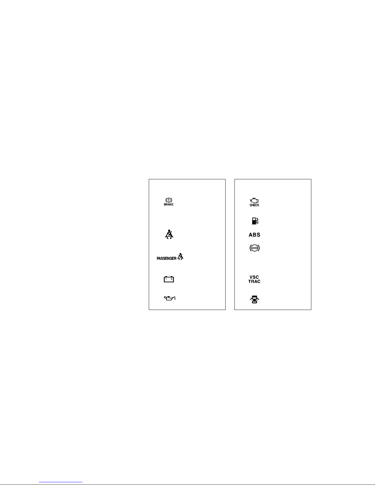
’02 4Runner_U (L/O 0108)
94
2002 MY 4RUNNER_U (OM35787U)
To change the meter display, quickly
push and release the knob. The meter
display changes in the order from the
odometer to trip meter A to trip meter
B, then back to the odometer each
time you push.
To reset the trip meter A to zero, display the meter A reading, then push
and hold the knob until the meter is
set to zero. The same process can be
applied for resetting the trip meter B.
If the indicator or
buzzer c omes on...
(a) If parking brake is
off, stop
immediately a nd
contact Toyota
dealer.
(b) Fasten driver ’s
seat belt.
(d) Stop and check.
(e) Stop and check.
(indicator and buzzer)
Do this.
(c) Fasten front
passenger’s seat
belt.
(h) Take vehicle to
Toyota dealer.
If brake sy stem
warning light is
also on, stop
immediately a nd
contact Toyota
dealer.
Do this.
or
(g) Fill up tank.
(f) Take vehicl e to
Toyota dealer.
(i) Take vehicle to
Toyota dealer.
If the indicator or
buzzer c omes on...
(j) Close all doors.
Service reminder indicators
and war ning b uzzers
 Loading...