

Page 1
−INTRODUCTION HOW TO USE THIS MANUAL
01−1
HOW TO USE THIS MANUAL
010B2−19
GENERAL INFORMATION
1. GENERAL DESCRIPTION
(a) This manual is made in accordance with SAE J2008.
(b) Generally, repair operations can be separated in the following 3 main processes:
1. Diagnosis
2. Removing and Installing, Replacing, Disassembling, Installing and Checking, Adjusting
3. Final Inspection
(c) This manual explains the 1st process of ”Diagnosis” (placed in the ”Diagnostics” section), the 2nd pro-
cess of ”Removing and Installing, Replacing, Disassembling, Installing and Checking, Adjusting”, but
the 3rd process of ”Final Inspection” is omitted.
(d) The following essential operations are not written in this manual. However, these operations must be
done in the practical situation.
(1) Operation with a jack or lift
(2) Cleaning of a removed part when necessary
(3) Visual check
2. INDEX
(a) An alphabetical INDEX is provided as a section on the end of the book to guide you to the item to be
repaired.
3. PREPARATION
(a) Use of special service tools (SST) and special service materials (SSM) may be required, depending
on the repairing condition. Be sure to use SST and SSM when they are required and follow the working
procedure properly. A list of SST and SSM is in the Preparation section of this manual.
4. REPAIR PROCEDURES
(a) Component drawing is placed under the title when necessary.
(b) Illustrations are placed as ”disassembled parts drawing” so that it enables you to understand the fitting
condition of the components.
(c) Non−reusable parts, grease applied parts, precoated parts and tightening torque are specified in the
components drawing.
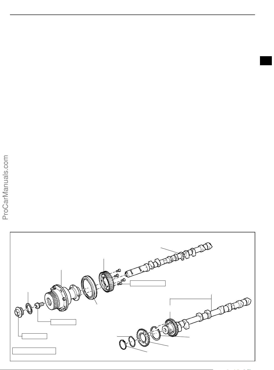
Example:
OVERHAUL
Camshaft Drive Gear
Camshaft Timing Tube Assy
Seal Washer
z Camshaft Setting Oil Seal
Screw Plug
78 (790, 58)
15 (150, 11)
N·m (kgf·cm, ft·lbf) : Specified torque
z Non−reusable part
1CD−FTV ENGINE REPAIR MANUAL (RM1046E)
Wave Washer
Camshaft,
No. 3 Camshaft Sub−assy
7.5 (80, 66 in.·lbf)
Camshaft Driven Main Gear
Camshaft Sub Gear
Snap Ring
No. 2 Camshaft,
No. 4 Camshaft Sub−assy
Camshaft Timing Gear
Bolt Washer
A54988
Page 2
01−2
−INTRODUCTION HOW TO USE THIS MANUAL
(d) Tightening torque, oil applying position, and non−reusable parts are described as important points in
the procedure.
NOTICE:
There are cases where such information can only be indicated by an illustration. In that case, all the
information such as torque, oil, etc. are described in the illustration.
(e) Installing procedure of operation items is performed in the reverse order of the removal, and only the
important points are described.
(f) Only items with points are described in the procedure, and the operational portion and content are
placed using an illustration. In the explanations, details of the operational method, standard value and
notice are placed.
(g) There may be a case where the illustrations of the similar models are used. In that case the details
may be different from the actual vehicle.
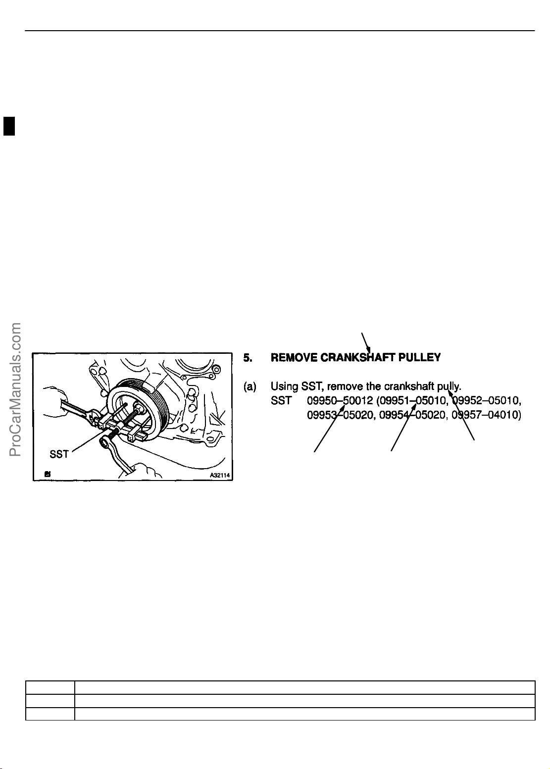
(h) The procedures are presented in a step−by−step format:
(1) The illustration shows what to do and where to do it.
(2) The task heading tells what to do.
(3) The detailed text tells how to perform the task and gives other information such as specifications
and warnings.
Example:
Task heading: what to do
Task heading: what to do
Illustration:
Illustration:
Illustration:
what to do and where
what to do and where
what to do and where
Task heading: what to do
Component part No.
Component part No.
Set part No.
Set part No.
Set part No.
Component part No.
Detailed text:
Detailed text:
Detailed text:
how to do task
how to do task
how to do task
A59974
HINT:
This format provides an experienced technician with a FAST TRACK to the necessary information. The task
heading can be read at a glance when necessary, and the text below provides detailed information. Important specifications and warnings always stand out in bold type.
5. SERVICE SPECIFICATIONS
(a) Specifications are presented in bold type throughout the manual. You never have to leave the proce-
dure to look up your specifications. The specifications are also found in the Service Specifications section for a quick reference.
6. TERMS DEFINITION
CAUTION
NOTICE Indicates the possibility of damage to the components being repaired.
HINT Provides additional information to help you to perform the repair efficiently.
1CD−FTV ENGINE REPAIR MANUAL (RM1046E)
Indicates the possibility of injury to you or other people.
Page 3
01−3
−INTRODUCTION HOW TO USE THIS MANUAL
7. SI UNIT
(a) The UNITS given in this manual are primarily expressed according to the SI UNIT (International Sys-
tem of Unit), and alternately expressed in the metric system and in the English System.
Example:
Torque: 30 N×m (310 kgf×cm, 22 ft×lbf)
1CD−FTV ENGINE REPAIR MANUAL (RM1046E)
Page 4
01−4
−INTRODUCTION REPAIR INSTRUCTION
REPAIR INSTRUCTION
010R3−01
PRECAUTION
1. TO PREVENT FROM ENTERING FOREIGN SUBSTANCES.
(a) When foreign substances such as dust, grain of sand or metallic dust enter inside of engine, it often
causes functional failure of the engine.
(1) Precaution before disassembly.
S Remove adequately all sand and mud adhere to the outside of engine .
(2) Precaution at reassembly.
S Protect disassembled parts from dust by using vinyl sheet to cover.
2. TO PREVENT SCRATCHES ON THE PARTS.
(a) The existence of scratches on the contact and revolving surfaces often causes oil leak and seisure.
(1) Precautions at disassembly and reassembly.
S When disassemble the contact surface of the parts, use plastic hummer striking lightly. (Do
not pry out by screwdriver).
S When fix the parts to the vise, do not directly catch it in the vise. Fix the parts through alumi-
num bar.
3. TO CLEAN AND WASH THE PARTS.
(a) Each parts needs to be well cleaned, washed, and dried by air, and apply specified oil before reas-
sembly.
(1) Cleaning and washing by alkaline solvent is prohibited:
S Parts made of aluminum and rubber. (ex. cylinder head cover gasket etc.)
(2) Cleaning and washing by flushing oil (ex. kerosene, white gasoline etc.) is prohibited:
S Parts made of rubber. (ex. cylinder head cover gasket etc.)
4. POSITION AND DIRECTION OF EACH PARTS.
(a) Each parts needs to be reassembled as the same position and direction as it disassembled.
(1) Precautions at disassembly and reassembly.
S Follow the directions when the manual designates to mark the matchmark and/or direction
5. INSTALL ENGINE ASSEMBLY TO OVERHAUL STAND WHEN OVERHAUL THE ENGINE.
6. PUT THE DISASSEMBLED PARTS IN ORDER AS THEY DISASSEMBLED.
7. APPLY ENGINE OIL TO THE SLIDING AND ROTATING SURFACES.
8. NON−REUSABLE PARTS SUCH AS GASKET AND SEAL NEEDS TO BE CHANGED TO THE NEW
PARTS.
9. BASIC REPAIR HINT
mark.
S Disassembled parts needs to be put in order as disassembled, not to change position and/
or direction.
S Follow the directions when the manual instructs the position and direction.
Seal Lock Adhesive
Z11554
1CD−FTV ENGINE REPAIR MANUAL (RM1046E)
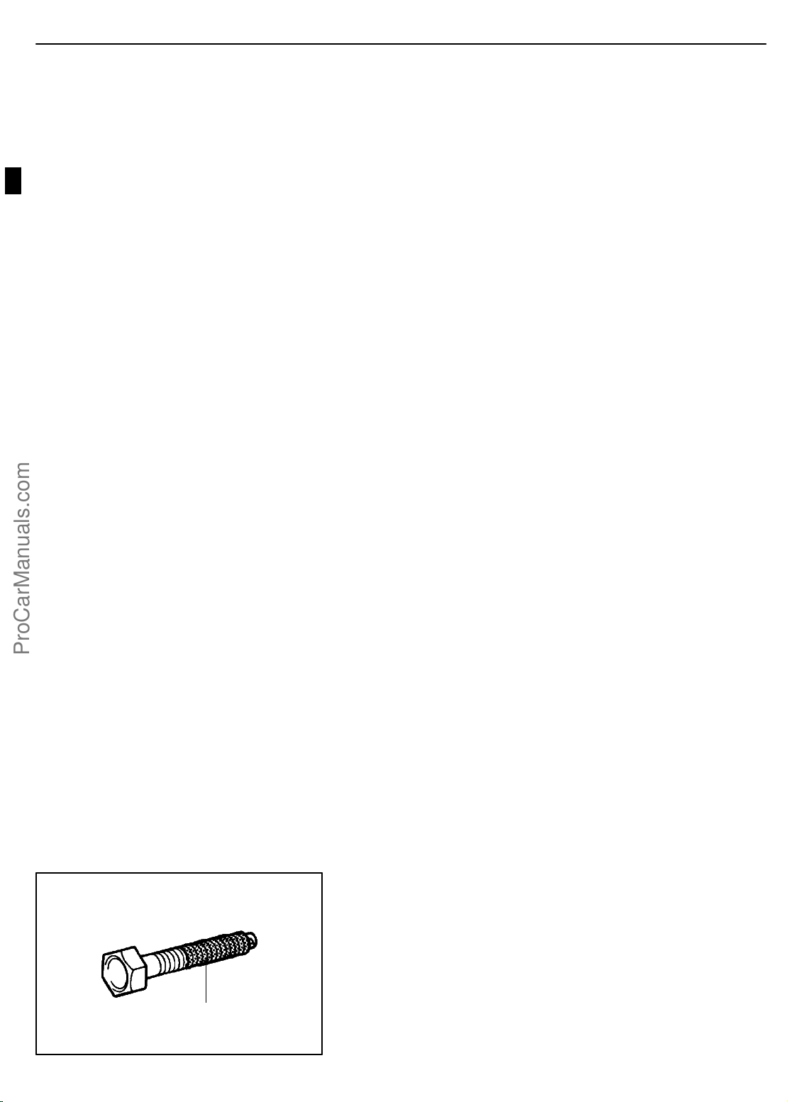
(a) Precoated Parts:
(1) Precoated parts are bolts, nuts, etc. that are coated
with a seal lock adhesive at the factory.
(2) If a precoated part is retightened, loosened or
caused to move in any way, it must be recoated with
the specified adhesive.
(3) When reusing precoated parts, clean off the old
adhesive and dry with compressed air. Then apply
the specified seal lock adhesive to the bolt, nut or
threads.
Page 5
−INTRODUCTION REPAIR INSTRUCTION
NOTICE:
Do the torque checking with the lower limit value of the torque tolerance.
(4) Depending on the seal lock agent to apply, there may be a case where it is necessary to leave
it for a specified time until it hardens.
(b) Gaskets:
When necessary, use a sealer on gaskets to prevent leaks.
(c) Bolts, Nuts and Screws:
Carefully observe all specifications for bolt tightening torques. Always use a torque wrench.
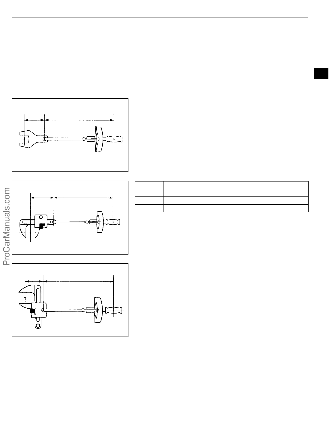
(d) Torque When Using Extension Tool with Torque Wrench:
(1) In case of tightening by extending the entire length
L1 L2L1 L2
of the torque wrench combined with SST or tool, if
you tighten until the reading of the torque wrench
reached the specified torque value, the actual
torque becomes excessive.
(2) In this text, only the specified torque is described.
In case of using SST or extension tool, find the read-
D02612
ing of the torque wrench by the formula.
(3) Formula T’=T x L2/(L1 + L2)
T’
L2L1 L2L1
T Torque {N×m (kgf×cm, ft×lbf)}
L1 Length of SST or tool (cm)
L2 Length of torque wrench (cm)
Reading of torque wrench {N×m (kgf×cm, ft×lbf)}
01−5
D01201
L2L1 L2L1
D01202
10. REMOVAL AND INSTALLATION OF FUEL CONTROL PARTS
(a) Place for Removing and Installing Fuel System Parts:
(1) Place with good air ventilation and without anything flammable such as welder, grinder, drill, elec-
tric motor or stove in the surroundings.
(2) Never work in a place like a pit or nearby pit as there is a possibility that vaporized fuel fills those
places.
(b) Removing and Installing of Fuel System Parts:
(1) Prepare a fire extinguisher before starting the operation.
(2) For prevention of the static electricity, install a ground on the fuel changer, vehicle and fuel tank,
and do not spray much water so as to prevent slipping.
1CD−FTV ENGINE REPAIR MANUAL (RM1046E)
Page 6
01−6
−INTRODUCTION REPAIR INSTRUCTION
(3) Never use any electric equipment like an electric motor or a working light as they may cause
spark or high temperature.
(4) Never use an iron hammer as it may cause spark.
(5) Dispose the shop lag separately from any fuel deposit.
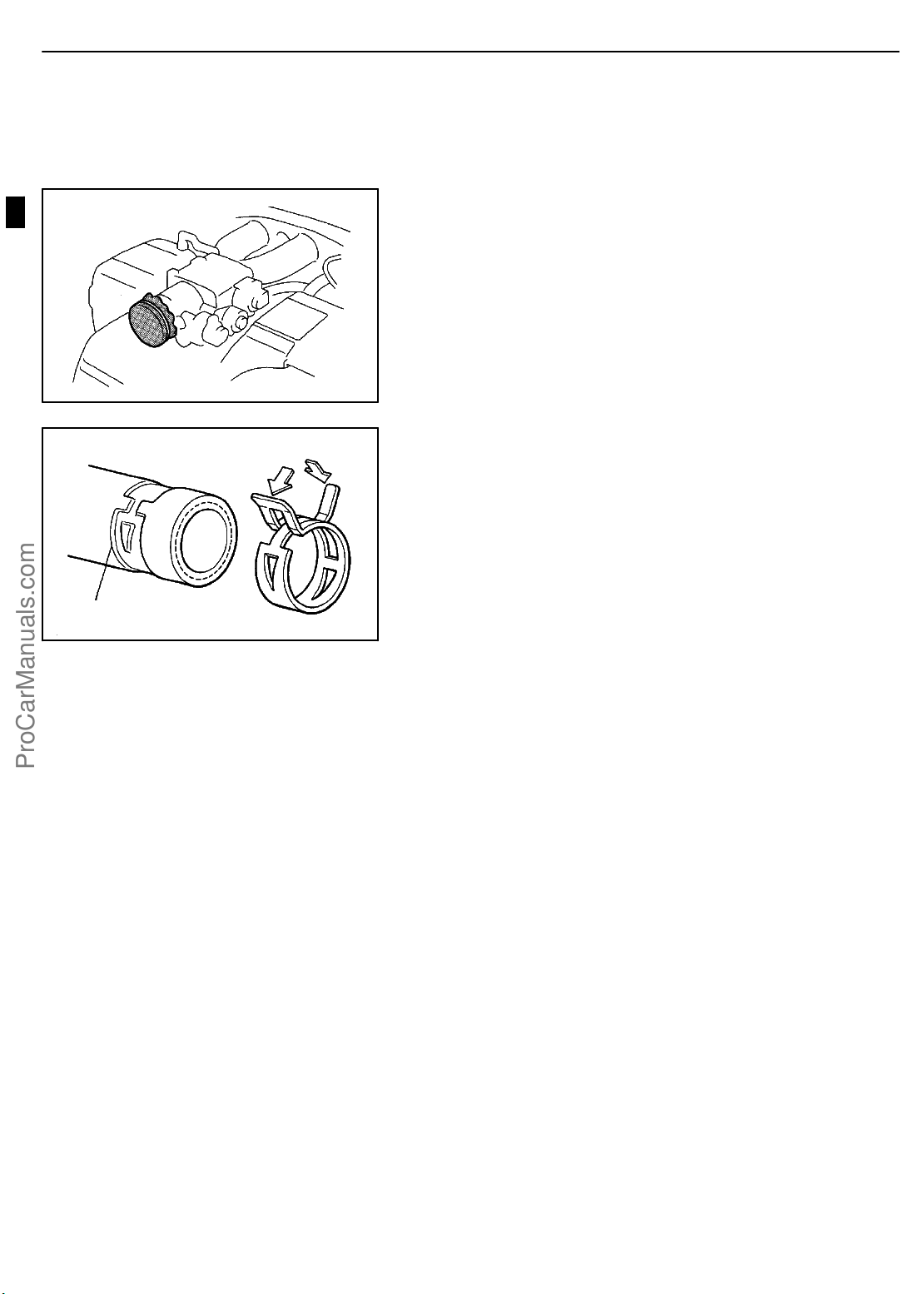
11. REMOVAL AND INSTALLATION OF ENGINE INTAKE
PARTS
(a) If any metal tip is mixed in the inlet pass, that may give a
bad effect to the engine and turbo charger.
(b) When removing and installing of the inlet system parts,
close the opening of the removed inlet system parts and
the engine with a clean shop lag or gum tape.
(c) When installing the inlet system parts, check that there is
D01563
no mixing of a metal tip.
Flat Spring Clamp
Clamp Track
12. HANDLING OF HOSE CLAMPS
(a) Before removing the hose, check the depth of inserting
portion and the clamp position to restore it surely.
(b) Change a deformed or dented into a new one.
(c) In case of reusing the hose, install the clamp on the hose
where it has a clamp track.
(d) For a flat spring type clamp, make it adjust by adding force
to the arrow mark direction after the installation.
D25081
1CD−FTV ENGINE REPAIR MANUAL (RM1046E)
Page 7
−INTRODUCTION TERMS
01−7
TERMS
ABBREVIATIONS USED IN MANUAL
Abbreviations
ABS Anti−Lock Brake System
A/C Air Conditioner
AC Alternating Current
ACC Accessory
ACIS Acoustic Control Induction System
ACSD Automatic Cold Start Device
A.D.D. Automatic Disconnecting Differential
A/F Air−Fuel Ratio
AHC Active Height Control Suspension
ALR Automatic Locking Retractor
ALT Alternator
AMP Amplifier
ANT Antenna
Approx. Approximately
ASSY Assembly
A/T, ATM Automatic Transmission (Transaxle)
ATF Automatic Transmission Fluid
AUTO Automatic
AUX Auxiliary
AVG Average
AVS Adaptive Variable Suspension
B+ Battery Voltage
BA Brake Assist
BACS Boost Altitude Compensation System
BAT Battery
BDC Bottom Dead Center
B/L Bi−Level
B/S Bore−Stroke Ratio
BTDC Before Top Dead Center
BVSV Bimetallic Vacuum Switching Valve
CAN Controller Area Network
CB Circuit Breaker
CCo Catalytic Converter For Oxidation
CD Compact Disc
CF Cornering Force
CG Center Of Gravity
CH Channel
CKD Complete Knock Down
COMB. Combination
CPE Coupe
CPS Combustion Pressure Sensor
CPU Central Processing Unit
CRS Child Restraint System
CTR Center
C/V Check Valve
CV Control Valve
CW Curb Weight
DC Direct Current
010B9−17
Meaning
1CD−FTV ENGINE REPAIR MANUAL (RM1046E)
Page 8
01−8
−INTRODUCTION TERMS
Abbreviations Meaning
DEF Defogger
DFL Deflector
DIFF. Differential
DIFF. LOCK Differential Lock
D/INJ Direct Injection
DLC Data Link Connector
DLI Distributorless Ignition
DOHC Double Overhead Camshaft
DP Dash Pot
DS Dead Soak
DSP Digital Signal Processor
DTC Diagnostic Trouble Code
DVD Digital Versatile Disc
EBD Electric Brake Force Distribution
ECAM Engine Control And Measurement System
ECD Electronic Controlled Diesel
ECDY Eddy Current Dynamometer
ECT Electronic Control Transmission
ECU Electronic Control Unit
ED Electro−Deposited Coating
EDU Electronic Driving Unit
EDIC Electric Diesel Injection Control
EFI Electronic Fuel Injection
E/G Engine
EGR Exhaust Gas Recirculation
EGR−VM EGR−Vacuum Modulator
ELR Emergency Locking Retractor
EMPS Electric Motor Power Steering
ENG Engine
ESA Electronic Spark Advance
ETCS−i Electronic Throttle Control System−intelligent
EVAP Evaporative Emission Control
EVP Evaporator
E−VRV Electric Vacuum Regulating Valve
EX Exhaust
FE Fuel Economy
FF Front−Engine Front−Wheel−Drive
F/G Fuel Gauge
FIPG Formed In Place Gasket
FL Fusible Link
F/P Fuel Pump
FPU Fuel Pressure Up
Fr Front
F/W Flywheel
FW/D Flywheel Damper
FWD Front−Wheel−Drive
GAS Gasoline
GND Ground
GPS Global Positioning System
HAC High Altitude Compensator
H/B Hatchback
1CD−FTV ENGINE REPAIR MANUAL (RM1046E)
Page 9
−INTRODUCTION TERMS
Abbreviations Meaning
H−FUSE High Current Fuse
HI High
HID High Intensity Discharge (Head Lamp)
HSG Housing
HT Hard Top
HWS Heated Windshield System
IC Integrated Circuit
IDI Indirect Diesel Injection
IFS Independent Front Suspension
IG Ignition
IIA Integrated Ignition Assembly
IN Intake (Manifold, Valve)
INT Intermittent
I/P Instrument Panel
IRS Independent Rear Suspension
ISC Idle Speed Control
J/B Junction Block
J/C Junction Connector
KD Kick−Down
LAN Local Area Network
LB Liftback
LCD Liquid Crystal Display
LED Light Emitting Diode
LH Left−Hand
LHD Left−Hand Drive
L/H/W Length, Height, Width
LLC Long−Life Coolant
LNG Liquified Natural Gas
LO Low
LPG Liquified Petroleum Gas
LSD Limited Slip Differential
LSP & PV Load Sensing Proportioning And Bypass Valve
LSPV Load Sensing Proportioning Valve
MAP Manifold Absolute Pressure
MAX. Maximum
MIC Microphone
MIL Malfunction Indicator Lamp
MIN. Minimum
MG1 Motor Generator No.1
MG2 Motor Generator No.2
MP Multipurpose
MPI Multipoint Electronic Injection
MPX Multiplex Communication System
M/T, MTM Manual Transmission (Transaxle)
MT Mount
MTG Mounting
N Neutral
NA Natural Aspiration
No. Number
O2S Oxygen Sensor
O/D Overdrive
01−9
1CD−FTV ENGINE REPAIR MANUAL (RM1046E)
Page 10
01−10
−INTRODUCTION TERMS
Abbreviations Meaning
OEM Original Equipment Manufacturing
OHC Overhead Camshaft
OHV Overhead Valve
OPT Option
ORVR On−board Refilling Vapor Recovery
O/S Oversize
P&BV Proportioning And Bypass Valve
PCS Power Control System
PCV Positive Crankcase Ventilation
PKB Parking Brake
PPS Progressive Power Steering
PTC Positive Temperature Coefficient
PS Power Steering
PTO Power Take−Off
P/W Power Window
R&P Rack And Pinion
RAM Random Access Memory
R/B Relay Block
RBS Recirculating Ball Type Steering
R/F Reinforcement
RFS Rigid Front Suspension
RH Right−Hand
RHD Right−Hand Drive
RLY Relay
ROM Read Only Memory
Rr Rear
RRS Rigid Rear Suspension
RWD Rear−Wheel Drive
SDN Sedan
SEN Sensor
SICS Starting Injection Control System
SOC State Of Charge
SOHC Single Overhead Camshaft
SPEC Specification
SPI Single Point Injection
SRS Supplemental Restraint System
SSM Special Service Materials
SST Special Service Tools
STD Standard
STJ Cold−Start Fuel Injection
SW Switch
SYS System
T/A Transaxle
TACH Tachometer
TBI Throttle Body Electronic Fuel Injection
TC Turbocharger
TCCS TOYOTA Computer−Controlled System
TCV Timing Control Valve
TDC Top Dead Center
TEMP. Temperature
TEMS TOYOTA Electronic Modulated Suspension
1CD−FTV ENGINE REPAIR MANUAL (RM1046E)
Page 11
−INTRODUCTION TERMS
Abbreviations Meaning
TFT Toyota Free−Tronic
TIS Total Information System For Vehicle Development
T/M Transmission
TMC TOYOTA Motor Corporation
TMMK TOYOTA Motor Manufacturing Kentucky, Inc.
TRC Traction Control System
TURBO Turbocharge
TWC Three−Way Catalyst
U/D Underdrive
U/S Undersize
VCV Vacuum Control Valve
VENT Ventilator
VIN Vehicle Identification Number
VPS Variable Power Steering
VSC Vehicle Stability Control
VSV Vacuum Switching Valve
VTV Vacuum Transmitting Valve
VVT−i Variable Valve Timing−intelligent
w/ With
WGN Wagon
W/H Wire Harness
w/o Without
WU−TWC Warm Up Three−way Catalytic Converter
WU−OC Warm Up Oxidation Catalytic Converter
1st First
2nd Second
2WD Two Wheel Drive Vehicle (4 x 2)
3rd Third
4th Fourth
4WD Four Wheel Drive Vehicle (4 x 4)
4WS Four Wheel Steering System
5th Fifth
01−11
1CD−FTV ENGINE REPAIR MANUAL (RM1046E)
Page 12
01−12
−INTRODUCTION TERMS
010BA−20
GLOSSARY OF SAE AND TOYOTA TERMS
This glossary lists all SAE−J1930 terms and abbreviations used in this manual in compliance with SAE recommendations, as well as their TOYOTA equivalents.
SAE
ABBREVIATIONS
A/C Air Conditioning Air Conditioner
ACL Air Cleaner Air Cleaner, A/CL
AIR Secondary Air Injection Air Injection (AI)
AP Accelerator Pedal −
B+ Battery Positive Voltage +B, Battery Voltage
BARO Barometric Pressure HAC
CAC Charge Air Cooler Intercooler
CARB Carburetor Carburetor
CFI Continuous Fuel Injection −
CKP Crankshaft Position Crank Angle
CL Closed Loop Closed Loop
CMP Camshaft Position Cam Angle
CPP Clutch Pedal Position −
CTOX Continuous Trap Oxidizer −
CTP Closed Throttle Position LL ON, Idle ON
DFI Direct Fuel Injection (Diesel) Direct Injection (DI/INJ)
DI Distributor Ignition −
DLC1
DLC2
DLC3
DTC Diagnostic Trouble Code Diagnostic Trouble Code
DTM Diagnostic Test Mode −
ECL Engine Control Level −
ECM Engine Control Module Engine ECU (Electronic Control Unit)
ECT Engine Coolant Temperature Coolant Temperature, Water Temperature (THW)
EEPROM Electrically Erasable Programmable Read Only Memory
EFE Early Fuel Evaporation Cold Mixture Heater (CMH), Heat Control Valve (HCV)
EGR Exhaust Gas Recirculation Exhaust Gas Recirculation (EGR)
EI Electronic Ignition Distributorless Ignition (DLI)
EM Engine Modification Engine Modification (EM)
EPROM Erasable Programmable Read Only Memory Programmable Read Only Memory (PROM)
EVAP Evaporative Emission Evaporative Emission Control (EVAP)
FC Fan Control −
FEEPROM
FEPROM Flash Erasable Programmable Read Only Memory −
FF Flexible Fuel −
FP Fuel Pump Fuel Pump
GEN Generator Alternator
GND Ground Ground (GND)
1CD−FTV ENGINE REPAIR MANUAL (RM1046E)
Data Link Connector 1
Data Link Connector 2
Data Link Connector 3
Flash Electrically Erasable Programmable
Read Only Memory
SAE TERMS
1: Check Connector
2: Total Diagnosis Communication Link (TDCL)
3: OBD II Diagnostic Connector
Electrically Erasable Programmable Read Only Memory
(EEPROM),
Erasable Programmable Read Only Memory (EPROM)
TOYOTA TERMS
()−−ABBREVIATIONS
−
Page 13
−INTRODUCTION TERMS
01−13
HO2S
IAC Idle Air Control Idle Speed Control (ISC)
IAT Intake Air Temperature Intake or Inlet Air Temperature
ICM Ignition Control Module −
IFI Indirect Fuel Injection Indirect Injection (IDL)
IFS Inertia Fuel−Shutoff −
ISC Idle Speed Control −
KS Knock Sensor Knock Sensor
MAF Mass Air Flow Air Flow Meter
MAP Manifold Absolute Pressure Manifold Pressure Intake Vacuum
MC Mixture Control
MDP Manifold Differential Pressure −
MFI Multiport Fuel Injection Electronic Fuel Injection (EFI)
MIL Malfunction Indicator Lamp Check Engine Lamp
MST Manifold Surface Temperature −
MVZ Manifold Vacuum Zone −
NVRAM Non−Volatile Random Access Memory −
O2S Oxygen Sensor Oxygen Sensor, O2Sensor (O2S)
OBD On−Board Diagnostic On−Board Diagnostic System (OBD)
OC Oxidation Catalytic Converter Oxidation Catalyst Convert (OC), CCo
OP Open Loop Open Loop
PAIR Pulsed Secondary Air Injection Air Suction (AS)
PCM Powertrain Control Module −
PNP Park/Neutral Position −
PROM Programmable Read Only Memory −
PSP Power Steering Pressure −
PTOX Periodic Trap Oxidizer
RAM Random Access Memory Random Access Memory (RAM)
RM Relay Module −
ROM Read Only Memory Read Only Memory (ROM)
RPM Engine Speed Engine Speed
SC Supercharger Supercharger
SCB Supercharger Bypass E−ABV
SFI Sequential Multiport Fuel Injection Electronic Fuel Injection (EFI), Sequential Injection
SPL Smoke Puff Limiter −
SRI Service Reminder Indicator −
SRT System Readiness Test −
ST Scan Tool −
TB Throttle Body Throttle Body
TBI Throttle Body Fuel Injection
TC Turbocharger Turbocharger
TCC Torque Converter Clutch Torque Converter
Heated Oxygen Sensor Heated Oxygen Sensor (HO2S)
Electric Bleed Air Control Valve (EBCV)
Mixture Control Valve (MCV)
Electric Air Control Valve (EACV)
Diesel Particulate Filter (DPF)
Diesel Particulate Trap (DPT)
Single Point Injection
Central Fuel Injection (Ci)
1CD−FTV ENGINE REPAIR MANUAL (RM1046E)
Page 14
01−14
−INTRODUCTION TERMS
TCM Transmission Control Module Transmission ECU, ECT ECU
TP Throttle Position Throttle Position
TR Transmission Range −
TVV Thermal Vacuum Valve
TWC Three−Way Catalytic Converter
TWC+OC Three−Way + Oxidation Catalytic Converter CCR+ CCo
VAF Volume Air Flow Air Flow Meter
VR Voltage Regulator Voltage Regulator
VSS Vehicle Speed Sensor Vehicle Speed Sensor
WOT Wide Open Throttle Full Throttle
WU−OC Warm Up Oxidation Catalytic Converter −
WU−TWC Warm Up Three−Way Catalytic Converter −
3GR Third Gear −
4GR Fourth Gear −
Bimetallic Vacuum Switching Valve (BVSV)
Thermostatic Vacuum Switching Valve (TVSV)
Three−Way Catalytic (TWC)
Manifold Converter
CC
RO
1CD−FTV ENGINE REPAIR MANUAL (RM1046E)
Page 15
−PREPARATION INTAKE
02−1
INTAKE
PREPARATION
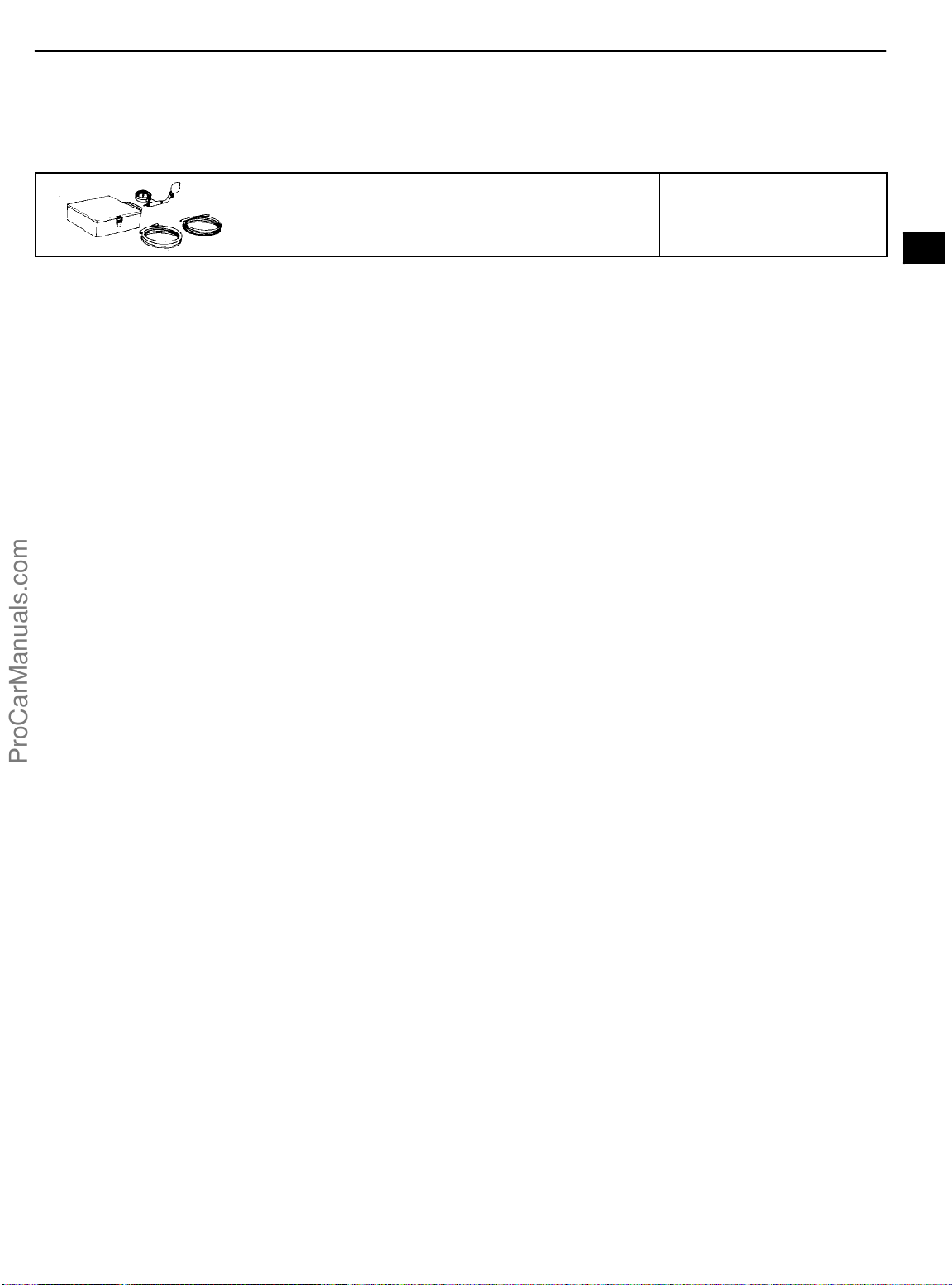
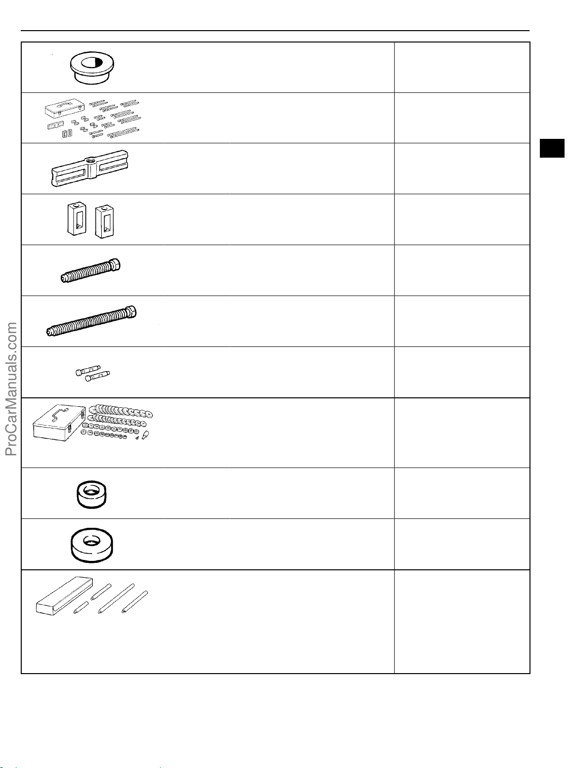
SST
09992−00242
023FS−01
Turbocharger Pressure Gauge TURBOCHARGER
SUB−ASSY(1CD−FTV)(From
September, 2003)
1CD−FTV ENGINE REPAIR MANUAL (RM1046E)
Page 16
02−2
−PREPARATION ENGINE MECHANICAL
ENGINE MECHANICAL
PREPARATION
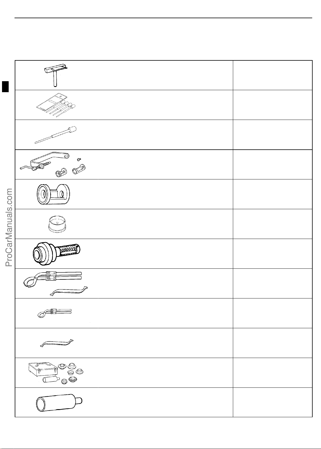
SST
09032−00100
09201−10000
(09201−01060)
09202−70020
(09202−00010)
023EZ−01
Oil Pan Seal Cutter PARTIAL ENGINE
ASSY(1CD−FTV)(From September,
2003)
Valve Guide Bushing Remover &
Replacer Set
Valve Guide Bushing Remover &
Replacer 6
Valve Spring Compressor CYLINDER HEAD
Attachment CYLINDER HEAD
CYLINDER HEAD
ASSY(1CD−FTV)(From September,
2003)
CYLINDER HEAD
ASSY(1CD−FTV)(From September,
2003)
ASSY(1CD−FTV)(From September,
2003)
ASSY(1CD−FTV)(From September,
2003)
09223−15030
09223−46011
09248−55050
(09248−05510)
(09248−05520)
09316−60011
Oil Seal & Bearing Replacer PARTIAL ENGINE
ASSY(1CD−FTV)(From September,
2003)
Crankshaft Front Oil Seal
Replacer
Valve Clearance Adjust Tool Set PARTIAL ENGINE
Valve Lifter Press PARTIAL ENGINE
Valve Lifter Stopper PARTIAL ENGINE
Transmission & Transfer Bearing
Replacer
PARTIAL ENGINE
ASSY(1CD−FTV)(From September,
2003)
ASSY(1CD−FTV)(From September,
2003)
ASSY(1CD−FTV)(From September,
2003)
ASSY(1CD−FTV)(From September,
2003)
PARTIAL ENGINE
ASSY(1CD−FTV)(From September,
2003)
(09316−00011)
1CD−FTV ENGINE REPAIR MANUAL (RM1046E)
Replacer Pipe PARTIAL ENGINE
ASSY(1CD−FTV)(From September,
2003)
Page 17
−PREPARATION ENGINE MECHANICAL
02−3
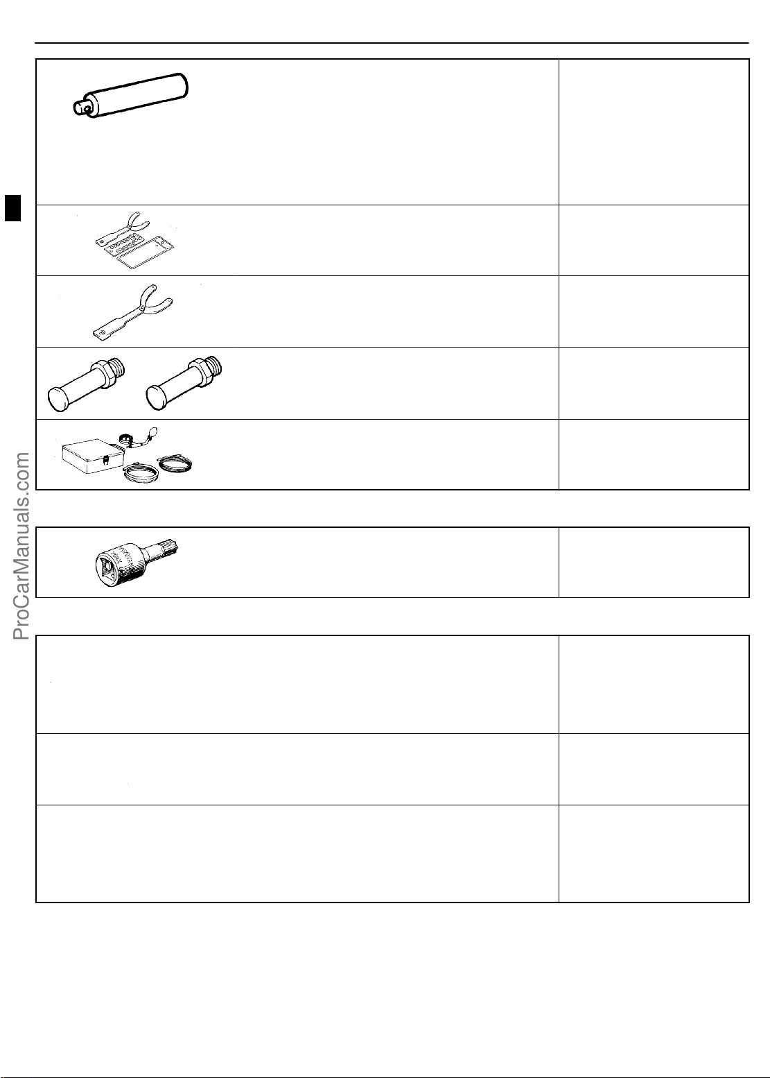
(09316−00021)
09950−50013
(09951−05010)
(09952−05010)
(09953−05010)
(09953−05020)
Replacer ”A” PARTIAL ENGINE
ASSY(1CD−FTV)(From September,
2003)
Puller C Set PARTIAL ENGINE
ASSY(1CD−FTV)(From September,
2003)
Hanger 150 PARTIAL ENGINE
ASSY(1CD−FTV)(From September,
2003)
Slide Arm PARTIAL ENGINE
ASSY(1CD−FTV)(From September,
2003)
Center Bolt 100 PARTIAL ENGINE
ASSY(1CD−FTV)(From September,
2003)
Center Bolt 150 PARTIAL ENGINE
ASSY(1CD−FTV)(From September,
2003)
(09954−05021)
09950−60010
(09951−00210)
(09951−00350)
09950−70010
Claw No.2 PARTIAL ENGINE
ASSY(1CD−FTV)(From September,
2003)
Replacer Set CYLINDER HEAD
ASSY(1CD−FTV)(From September,
2003)
CYLINDER BLOCK
ASSY(1CD−FTV)(From September,
2003)
Replacer 21 CYLINDER HEAD
ASSY(1CD−FTV)(From September,
2003)
Replacer 35 CYLINDER BLOCK
ASSY(1CD−FTV)(From September,
2003)
Handle Set PARTIAL ENGINE
ASSY(1CD−FTV)(From September,
2003)
CYLINDER HEAD
ASSY(1CD−FTV)(From September,
2003)
CYLINDER BLOCK
ASSY(1CD−FTV)(From September,
2003)
1CD−FTV ENGINE REPAIR MANUAL (RM1046E)
Page 18
02−4
−PREPARATION ENGINE MECHANICAL
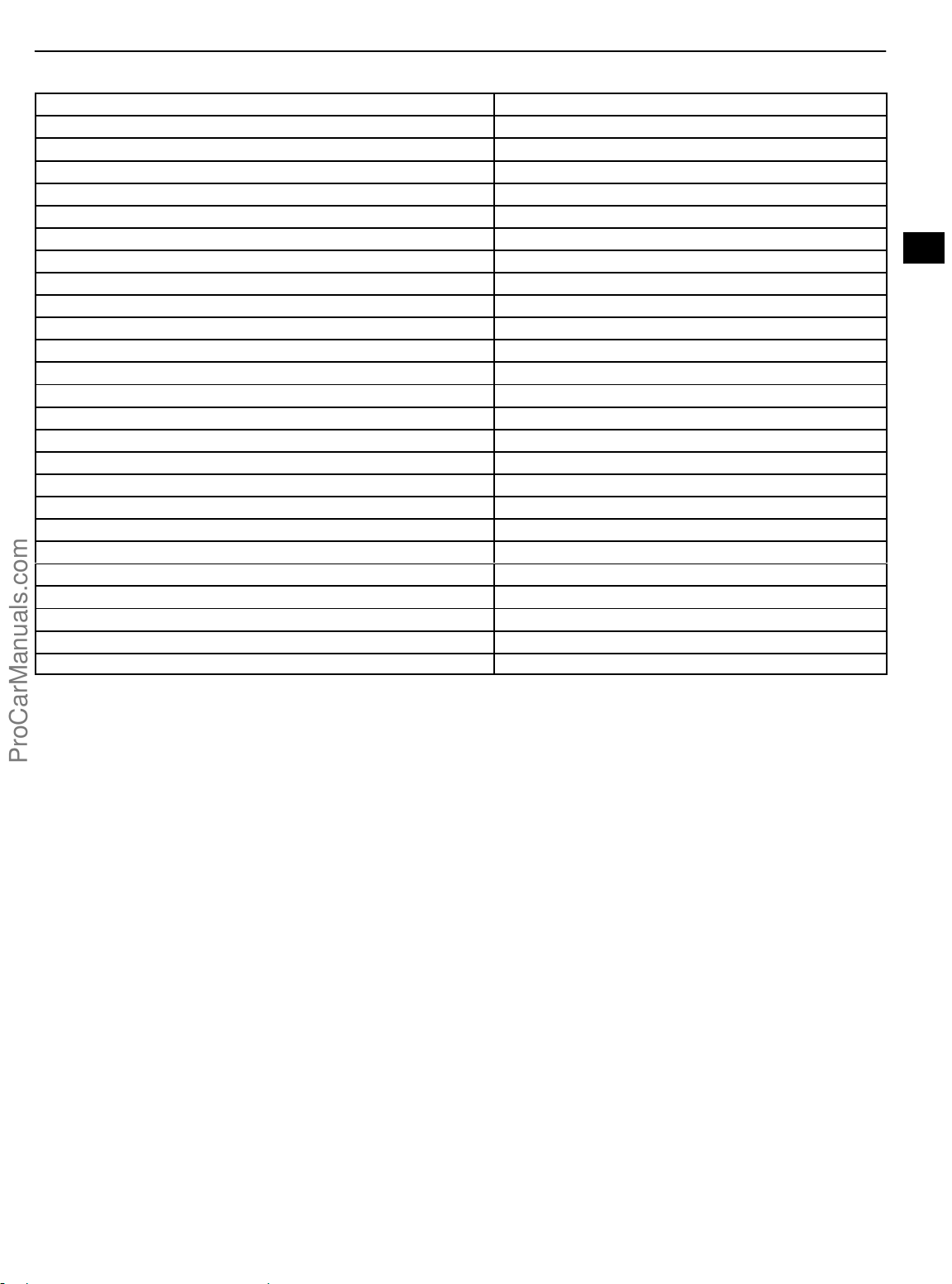
(09951−07100)
09960−10010
(09962−01000)
(09963−01000)
09992−00242
Handle 100 PARTIAL ENGINE
ASSY(1CD−FTV)(From September,
2003)
CYLINDER HEAD
ASSY(1CD−FTV)(From September,
2003)
CYLINDER BLOCK
ASSY(1CD−FTV)(From September,
2003)
Variable Pin Wrench Set PARTIAL ENGINE
ASSY(1CD−FTV)(From September,
2003)
Variable Pin Wrench Arm Assy PARTIAL ENGINE
ASSY(1CD−FTV)(From September,
2003)
Pin 10 PARTIAL ENGINE
ASSY(1CD−FTV)(From September,
2003)
Turbocharger Pressure Gauge PARTIAL ENGINE
ASSY(1CD−FTV)(From September,
2003)
Recommended Tools
SSM
09042−00020
08826−00080
08826−00100
08833−00070
Torx Socket T40 PARTIAL ENGINE
ASSY(1CD−FTV)(From September,
2003)
Seal Packing Black or equivalent
(FIPG)
”Seal Packing 1282B,”
THREE BOND 1282B or equivalent
(FIPG)
”Adhesive 1324,”
THREE BOND 1324 or equivalent
PARTIAL ENGINE
ASSY(1CD−FTV)(From September,
2003)
CYLINDER HEAD
ASSY(1CD−FTV)(From September,
2003)
PARTIAL ENGINE
ASSY(1CD−FTV)(From September,
2003)
CYLINDER HEAD
ASSY(1CD−FTV)(From September,
2003)
CYLINDER BLOCK
ASSY(1CD−FTV)(From September,
2003)
1CD−FTV ENGINE REPAIR MANUAL (RM1046E)
Page 19
Equipment
V−block
Piston ring compressor
Piston ring expander
Valve seat cutter
Hexagon wrench (6 mm)
Hexagon wrench (8 mm)
Connecting rod aligner
Cylinder gauge
Dial indicator
Feeler gauge
Micrometer
Precision straight edge
Steel square
Torque wrench
Vernier calipers
Dial indicator with magnetic base
Slide calipers
Wooden block
Spring tester
Plastigage
Heater
Dye penetrate
Caliper gauge
Reamer
Plastic−faced hammer
Ridge reamer
02−5
−PREPARATION ENGINE MECHANICAL
1CD−FTV ENGINE REPAIR MANUAL (RM1046E)
Page 20
02−6
−PREPARATION LUBRICATION
LUBRICATION
PREPARATION
Equipment
Feeler gauge
023F0−01
1CD−FTV ENGINE REPAIR MANUAL (RM1046E)
Page 21
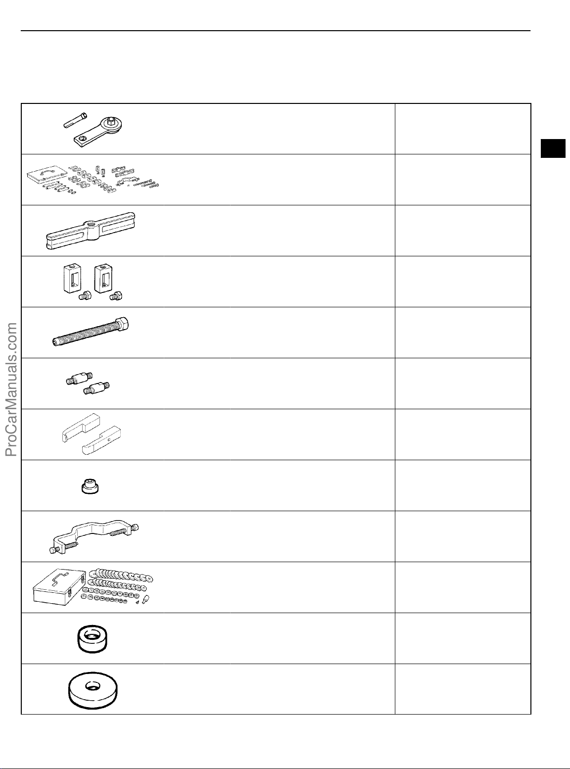
−PREPARATION STARTING & CHARGING
02−7
STARTING & CHARGING
PREPARATION
SST
09820−63020
09950−40011
(09951−04020)
(09952−04010)
(09953−04020)
023FT−01
Alternator Pulley Wrench Set GENERATOR
ASSY(1CD−FTV)(From September,
2003)
Puller B Set GENERATOR
ASSY(1CD−FTV)(From September,
2003)
Hanger 200 GENERATOR
ASSY(1CD−FTV)(From September,
2003)
Slide Arm GENERATOR
ASSY(1CD−FTV)(From September,
2003)
Center Bolt 150 GENERATOR
ASSY(1CD−FTV)(From September,
2003)
(09954−04010)
(09955−04071)
(09957−04010)
(09958−04011)
09950−60010
(09951−00250)
Arm 25 GENERATOR
ASSY(1CD−FTV)(From September,
2003)
Claw No.7 GENERATOR
ASSY(1CD−FTV)(From September,
2003)
Attachment GENERATOR
ASSY(1CD−FTV)(From September,
2003)
Holder GENERATOR
ASSY(1CD−FTV)(From September,
2003)
Replacer Set GENERATOR
ASSY(1CD−FTV)(From September,
2003)
Replacer 25 GENERATOR
ASSY(1CD−FTV)(From September,
2003)
(09951−00470)
1CD−FTV ENGINE REPAIR MANUAL (RM1046E)
Replacer 47 GENERATOR
ASSY(1CD−FTV)(From September,
2003)
Page 22
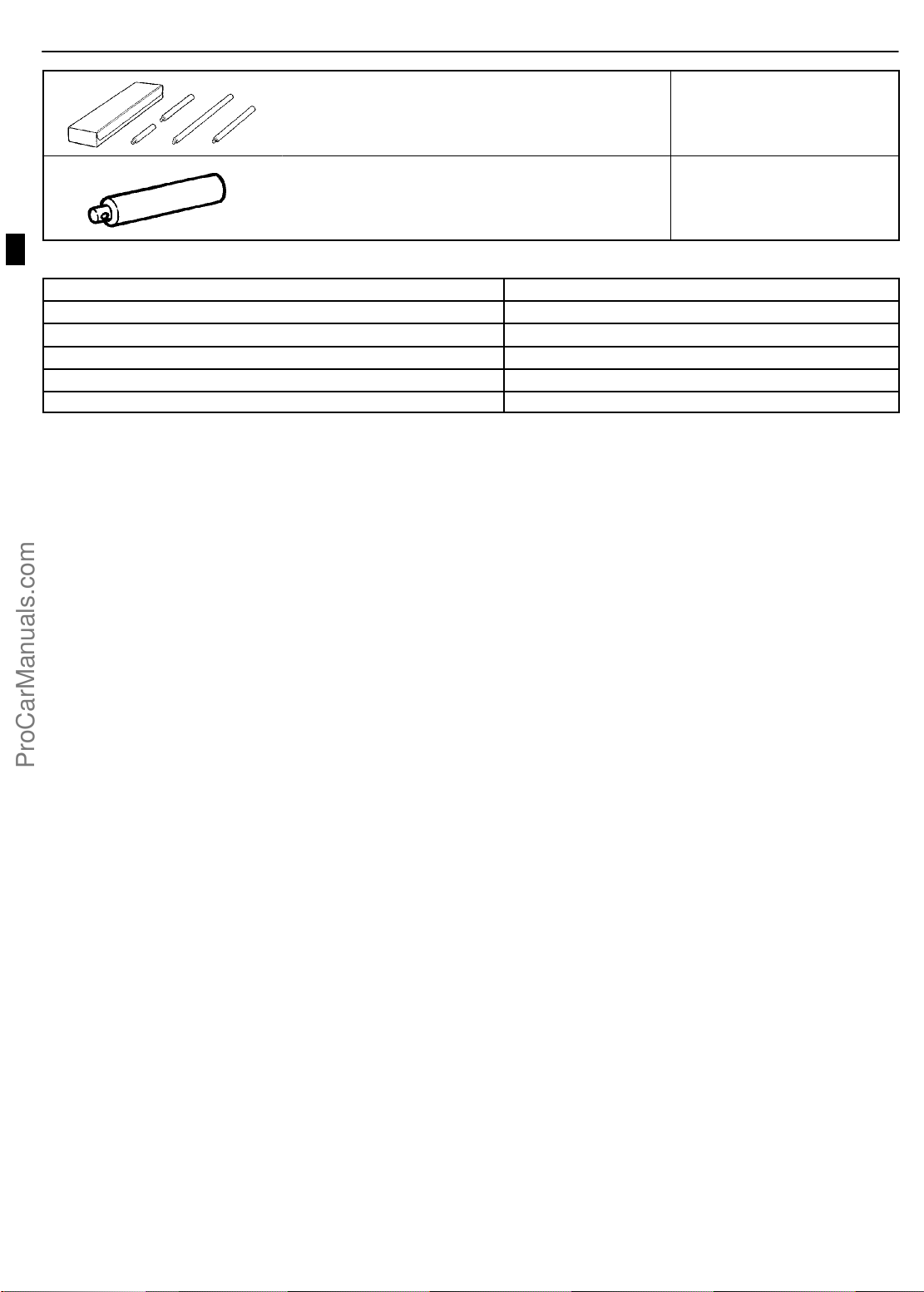
02−8
−PREPARATION STARTING & CHARGING
Equipment
Ohmmeter
Torque wrench
Vernier calipers
Pull scale
V−block
Dial indicator with magnetic base
09950−70010
(09951−07100)
Handle Set GENERATOR
ASSY(1CD−FTV)(From September,
2003)
Handle 100 GENERATOR
ASSY(1CD−FTV)(From September,
2003)
1CD−FTV ENGINE REPAIR MANUAL (RM1046E)
Page 23
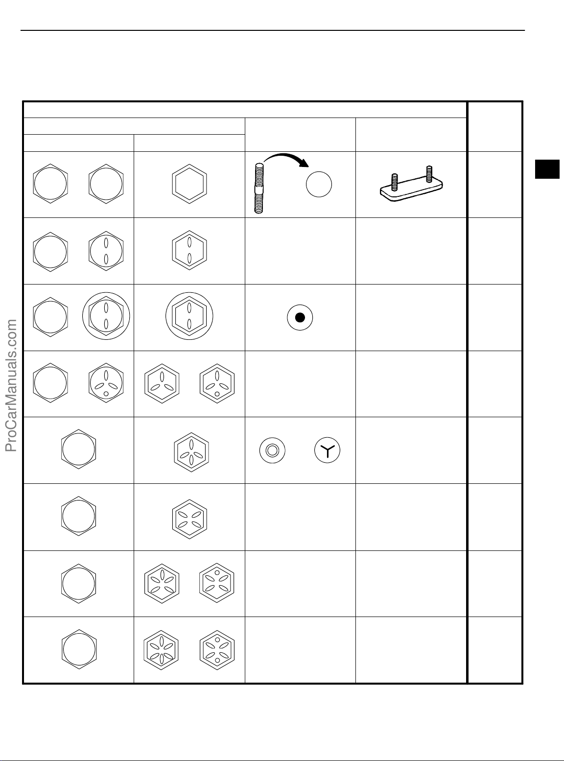
−SERVICE SPECIFICATIONS STANDARD BOLT
03−1
STANDARD BOLT
HOW TO DETERMINE BOLT STRENGTH
Bolt Type
Hexagon Head Bolt
Normal Recess Bolt Deep Recess Bolt
Stud Bolt Weld Bolt
4
No Mark
No Mark
No Mark
5
6
030LK−08
Class
4T
5T
6T
w/ Washer
7
8
9
10
w/ Washer
7T
8T
9T
10T
11
1CD−FTV ENGINE REPAIR MANUAL (RM1046E)
11T
B06431
Page 24
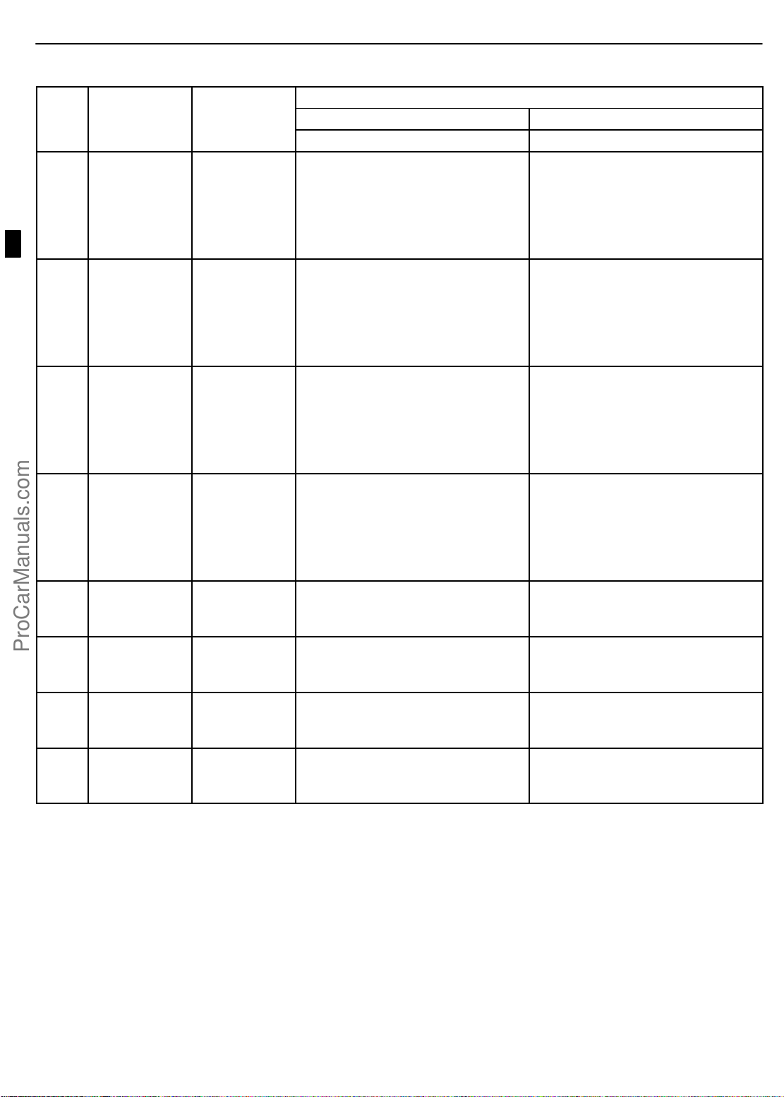
03−2
Class
−SERVICE SPECIFICATIONS STANDARD BOLT
SPECIFIED TORQUE FOR STANDARD BOLTS
030LL−08
Class
4T
5T
6T
7T
8T
9T
10T
11T
Diameter
mm mm
6
8
10
12
14
16
6
8
10
12
14
16
6
8
10
12
14
16
6
8
10
12
14
16
8
10
12
8
10
12
8
10
12
8
10
12
Pitch
1
1.25
1.25
1.25
1.5
1.5
1
1.25
1.25
1.25
1.5
1.5
1
1.25
1.25
1.25
1.5
1.5
1
1.25
1.25
1.25
1.5
1.5
1.25
1.25
1.25
1.25
1.25
1.25
1.25
1.25
1.25
1.25
1.25
1.25
Specified torque
Hexagon head bolt Hexagon flange bolt
N·m kgf·cm ft·lbf N·m kgf·cm ft·lbf
5
12.5
26
47
74
115
6.5
15.5
32
59
91
140
8
19
39
71
110
170
10.5
25
52
95
145
230
29
61
110
34
70
125
38
78
140
42
87
155
55
130
260
480
760
1,150
65
160
330
600
930
1,400
80
195
400
730
1,100
1,750
110
260
530
970
1,500
2,300
300
620
1,100
340
710
1,300
390
800
1,450
430
890
1,600
48 in.·lbf
9
19
35
55
83
56 in.·lbf
12
24
43
67
101
69 in.·lbf
14
29
53
80
127
8
19
38
70
108
166
22
45
80
25
51
94
28
58
105
31
64
116
6
14
29
53
84
−
7.5
17.5
36
65
100
−
9
21
44
80
125
−
12
28
58
105
165
−
33
68
120
37
78
140
42
88
155
47
97
175
60
145
290
540
850
−
75
175
360
670
1,050
−
90
210
440
810
1,250
−
120
290
590
1,050
1,700
−
330
690
1,250
380
790
1,450
430
890
1,600
480
990
1,800
52 in.·lbf
10
21
39
61
−
65 in.·lbf
13
26
48
76
−
78 in.·lbf
15
32
59
90
−
9
21
43
76
123
−
24
50
90
27
57
105
31
64
116
35
72
130
1CD−FTV ENGINE REPAIR MANUAL (RM1046E)
Page 25
−SERVICE SPECIFICATIONS STANDARD BOLT
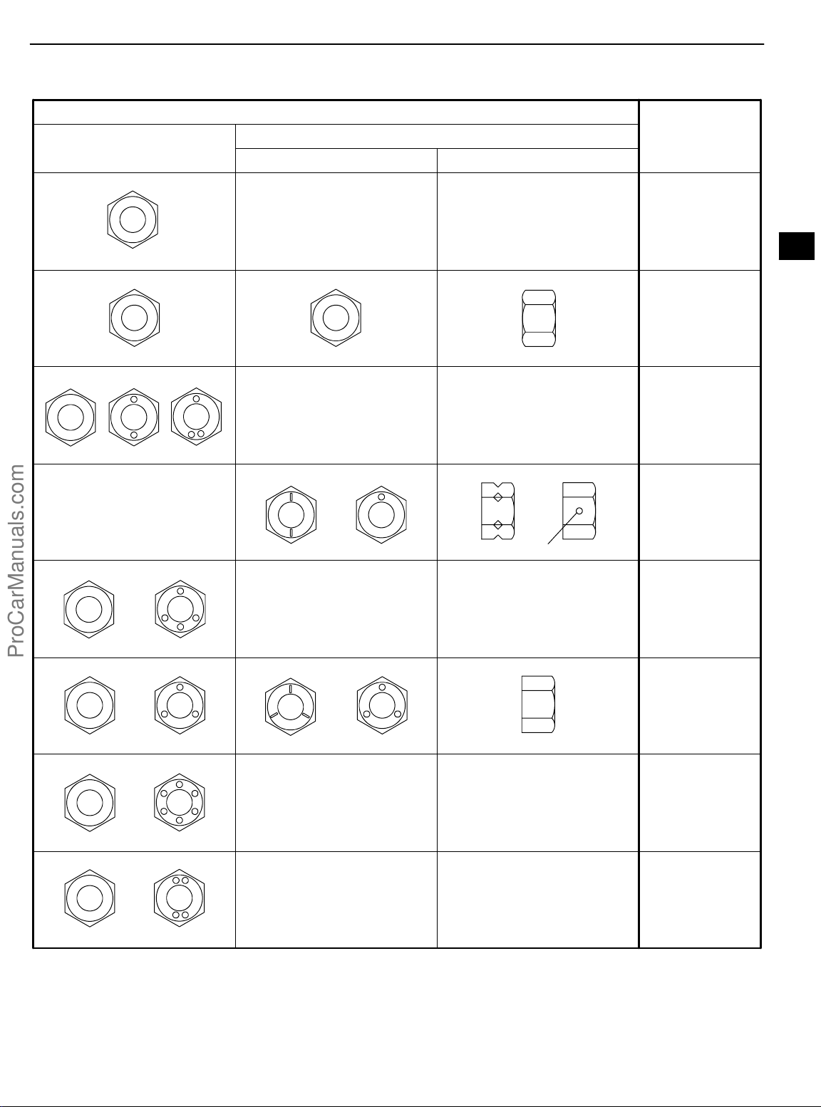
HOW TO DETERMINE NUT STRENGTH
Nut Type
03−3
030LM−08
Present Standard
Hexagon Nut
No Mark
No Mark (w/ Washer)
6N
Old Standard Hexagon Nut
Cold Forging Nut Cutting Processed Nut
No Mark (w/ Washer)
No Mark
*
Class
4N
5N (4T)
6N
7N (5T)
8N
8N
10N (7T)
10N
No Mark
11N
11N
12N
12N
*: Nut with 1 or more marks on one side surface of the nut.
HINT:
Use the nut with the same number of the nut strength classification or the greater than the bolt strength classification number when tightening parts with a bolt and nut.
Example: Bolt = 4T
Nut = 4N or more
1CD−FTV ENGINE REPAIR MANUAL (RM1046E)
B06432
Page 26
03−4
−SERVICE SPECIFICATIONS INTAKE
INTAKE
SERVICE DATA
Actuator push rod
Standard stroke 50 kpa (375 mmHg, 15 in. Hg)
30 kpa (225 mmHg, 9 in. Hg)
031FQ−03
0.2 mm (0.008 in.)
5.0 mm (0.197 in.)
1CD−FTV ENGINE REPAIR MANUAL (RM1046E)
Page 27
−SERVICE SPECIFICATIONS ENGINE MECHANICAL
03−5
ENGINE MECHANICAL
SERVICE DATA
Valve clearance
Intake (cold)
Exhaust
Adjusting shim thickness Mark 2.500
Mark 2.550
Mark 2.600
Mark 2.650
Mark 2.700
Mark 2.750
Mark 2.800
Mark 2.850
Mark 2.900
Mark 2.950
Mark 3.000
Mark 3.050
Mark 3.100
Mark 3.150
Mark 3.200
Mark 3.250
Mark 3.300
Cylinder head
Warpage Cylinder block side
Intake manifold side
Exhaust manifold side
Intake valve
Overall length Standard
Minimum
Valve stem diameter
Margin thickness Standard
Minimum
Exhaust valve
Overall length Standard
Valve stem diameter
Margin thickness Standard
Inner compression spring
Free length
Deviation Maximum
Installed tension at 31.1 mm (1.224 in.)
Intake Valve guide bush
Bushing inside diameter
Oil clearance Standard
Diameter
Protrusion height
Exhaust valve guide bush
Bushing inside diameter
Oil clearance Standard
Diameter
Protrusion height
Valve lifter
Lifter diameter
Lifter bore diameter
Oil clearance Standard
Minimum
Minimum
Maximum
Maximum
031H1−03
0.20 to 0.30 mm (0.008 to 0.012 in.)
0.35 to 0.45 mm (0.014 to 0.018 in.)
2.500 mm (0.0984 in.)
2.550 mm (0.1004 in.)
2.600 mm (0.1024 in.)
2.650 mm (0.1043 in.)
2.700 mm (0.1063 in.)
2.750 mm (0.1083 in.)
2.800 mm (0.1102 in.)
2.850 mm (0.1122 in.)
2.900 mm (0.1142 in.)
2.950 mm (0.1161 in.)
3.000 mm (0.1181 in.)
3.050 mm (0.1201 in.)
3.100 mm (0.1220 in.)
3.150 mm (0.1240 in.)
3.200 mm (0.1260 in.)
3.250 mm (0.1280 in.)
3.300 mm (0.1299 in.)
0.08 mm (0.0031 in.)
0.20 mm (0.0079 in.)
0.20 mm (0.0079 in.)
102.53 mm (4.0366in.)
102.10 mm (4.0197in.)
5.970 to 5.985 mm (0.2350 to 0.2356 in.)
0.9 (0.035 in.)
0.6 mm (0.0236 in.)
101.97 mm (4.0146in.)
101.55 mm (3.9980 in.)
5.960 to 5.975 mm (0.2346 to 0.2352 in.)
0.9 mm (0.035 in.)
0.6 mm (0.024 in.)
40.45 mm (1.5925 in.)
2.0 mm (0.079 in.)
177 to 195 N (18.0 to 19.9 kgf, 39.7 to 44.1 lbf)
6.010 to 6.030 mm (0.2366 to 0.2374 in.)
0.025 to 0.060 mm (0.0010 to 0.0024 in.)
0.08 mm (0.0031 in.)
10.985 to 11.006 mm (0.4325 to 0.4333 in.)
10.05 to 10.45 mm (0.3957 to 0.4114 in.)
6.010 to 6.030 mm (0.2366 to 0.2374 in.)
0.035 to 0.070 mm (0.0014 to 0.0028 in.)
0.10 mm (0.0039 in.)
10.985 to 11.006 mm (0.4325 to 0.4333 in.)
9.65 to 10.05 mm (0.3799 to 0.3957 in.)
27.975 to 27.985 mm (1.1014 to 1.1018 in.)
28.010 to 28.031 mm (1.1028 to 1.1036 in.)
0.025 to 0.080 mm (0.0010 to 0.0031 in.)
1CD−FTV ENGINE REPAIR MANUAL (RM1046E)
Page 28
03−6
Camshaft
Circle runout Maximum
Cam lobe height (intake) Standard
Minimum
Cam lobe height (exhaust) Standard
Minimum
Journal diameter
Thrust clearance
Oil clearance Standard
Gear backlash Standard
Connecting rod
Thrust clearance Standard
Oil clearance Standard
Maximum
Cylinder block
Warpage Maximum
Bore diameter Standard
Piston
Piston diameter
Piston oil clearance Standard
Bushing inside diameter
Piston pin
Piston pin diameter
Oil clearance Standard
Cylinder head set bolt
Out side diameter Standard
Connecting rod bolt
Diameter Standard
Connecting rod
Out−of−alignment Maximum per 100 mm (3.94 in.)
Rod twist Maximum per 100 mm (3.94 in.)
Ring groove clearance No. 1
Piston ring end gap
Standard No. 1
Maximum No. 1
Crankshaft
Thrust clearance Standard
Circle runout Maximum
Crank pin taper and out− of −round Maximum
Crank pin diameter
Main journal diameter
Oil clearance Standard
−SERVICE SPECIFICATIONS ENGINE MECHANICAL
0.06 mm (0.0024 in.)
46.57 to 46.67 mm (1.8335 to 1.8374 in.)
46.10 mm (1.8150 in.)
47.52 to 47.62 mm (1.8709 to 1.8748 in.)
47.05 mm (1.8524 in.)
26.969 to 26.985 mm (1.0618 to 1.0624 in.)
0.035 to 0.11 mm (0.0014 to 0.0043 in.)
0.025 to 0.080 mm (0.0010 to 0.0031 in.)
0.014 to 0.170 mm (0.0006 to 0.0067 in.)
0.08 to 0.40 mm (0.0031 to 0.0157 in.)
0.038 to 0.056 mm (0.0015 to 0.0022 in.)
0.10 mm (0.0039 in.)
0.05 mm (0.0020 in.)
82.200 to 82.400 mm (3.2362 to 3.2441 in.)
82.118 to 82.132 mm (3.2330 to 3.2335 in.)
0.068 to 0.140 mm (0.0027 to 0.0055 in.)
31.015 to 31.027 mm (1.2211 to 1.2215 in.)
31.000 to 31.012 mm (1.2205 to 1.2209 in.)
0.005 to 0.019 mm (0.0002 to 0.0007 in.)
10.40 to 11.00 mm (0.4094 to 0.4331 in.)
8.0 to 8.3 mm (0.315 to 0.315 in.)
0.05 mm (0.0020 in.)
0.15 mm (0.0059 in.)
0.11 to 0.15 mm (0.0043 to 0.0059 in.)
No. 2
0.075 to 0.115 mm (0.0030 to 0.0045 in.)
0.03 to 0.07 mm (0.0012 to 0.0028 in.)
Oil
0.27 to 0.39 mm (0.0106 to 0.0514 in.)
0.39 to 0.54 mm (0.0154 to 0.0213 in.)
No. 2
0.20 to 0.40 mm (0.0079 to 0.0157 in.)
Oil
0.82 mm (0.0323 in.)
1.00 mm (0.0394 in.)
No. 2
0.90 mm (0.0354 in.)
Oil
0.040 to 0.300 mm (0.0016 to 0.0118 in.)
0.025 mm (0.0010 in.)
0.01 mm (0.0004 in.)
50.482 to 50.500 mm (1.9875 to 1.9882 in.)
56.992 to 57.010 mm (2.2438 to 2.2445 in.)
0.032 to 0.100 mm (0.0013 to 0.0039 in.)
1CD−FTV ENGINE REPAIR MANUAL (RM1046E)
Page 29
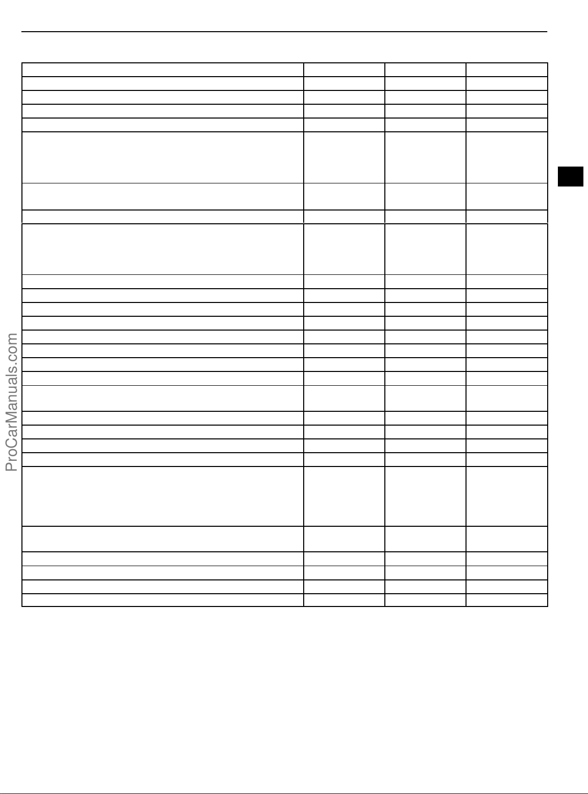
TORQUE SPECIFICATION
03−7
−SERVICE SPECIFICATIONS ENGINE MECHANICAL
031H2−03
Part Tightened
Cylinder block water drain cock x Cylinder block 29 291 21
Oil check valve x Cylinder block 33 331 24
Engine rear oil seal retainer x Cylinder block 7.4 75 65 in.×lbf
Oil pump x Cylinder block 31 320 23
Oil pan x Cylinder block (See page 14−4) Bolt A
Bolt B
Bolt C
Nut D
Oil strainer x Oil pan sub−assy Bolt
Nut
Oil pan No.2 x Oil pan sub−assy 12 11 9 9.0
Cylinder head x Cylinder block 1st
2nd
3rd
4th
Camshaft bearing cap x Cylinder head 20 204 15
Water pump x Cylinder block 31 320 23
Camshaft oil seal retainer x Cylinder head 9.8 100 7.2
Timing belt idler Sub assy No.2 x Oil pump 47 475 34
Timing belt idler No. 1 x Cylinder head 35 357 26
Camshaft timing pulley x Camshaft 88 899 65
Exhaust fuel addition injector x Cylinder head 12 117 8.5
Nozzle holder clamp x Cylinder head 26 265 19
Nozzle leakage pipe x Cylinder head Hollow screw
Flange bolt
Over flow screw x Plug 9.8 100 7.0
Check valve x Cylinder head 21 214 15
Cylinder head cover x Cylinder head 13 135 9.7
Taper screw plug No.1 x Cylinder head 25 255 18
Cylinder head stud bolt (See Page 14−27) Bolt A
Bolt B
Bolt C
Bolt D
Bolt E
Connecting rod cap x Connecting rod 1st
2nd
Crankshaft bearing cap x Cylinder block 11 5 1,173 85
Cylinder block stud bolt 2.9 30 27 in.×lbf
Cylinder block oil orifice x Cylinder block 9.0 92 80 in.×lbf
Oil nozzle No.1 x Cylinder block 7.4 75 65 in.×lbf
N×m kgf×cm ft×lbf
42
21
11
11
21
13
45
Turn 90˚
Turn 90˚
Turn 90˚
16
20
8.8
12
28
8.8
8.8
30
Turn 90_
428
209
112
112
209
135
459
Turn 90˚
Turn 90˚
Turn 90˚
163
204
90
120
286
90
90
306
Turn 90_
Turn 90˚
Turn 90˚
Turn 90˚
78 in.×lbf
78 in.×lbf
78 in.×lbf
Turn 90_
31
15
8
8
15
10
33
12
15
8.7
21
22
1CD−FTV ENGINE REPAIR MANUAL (RM1046E)
Page 30
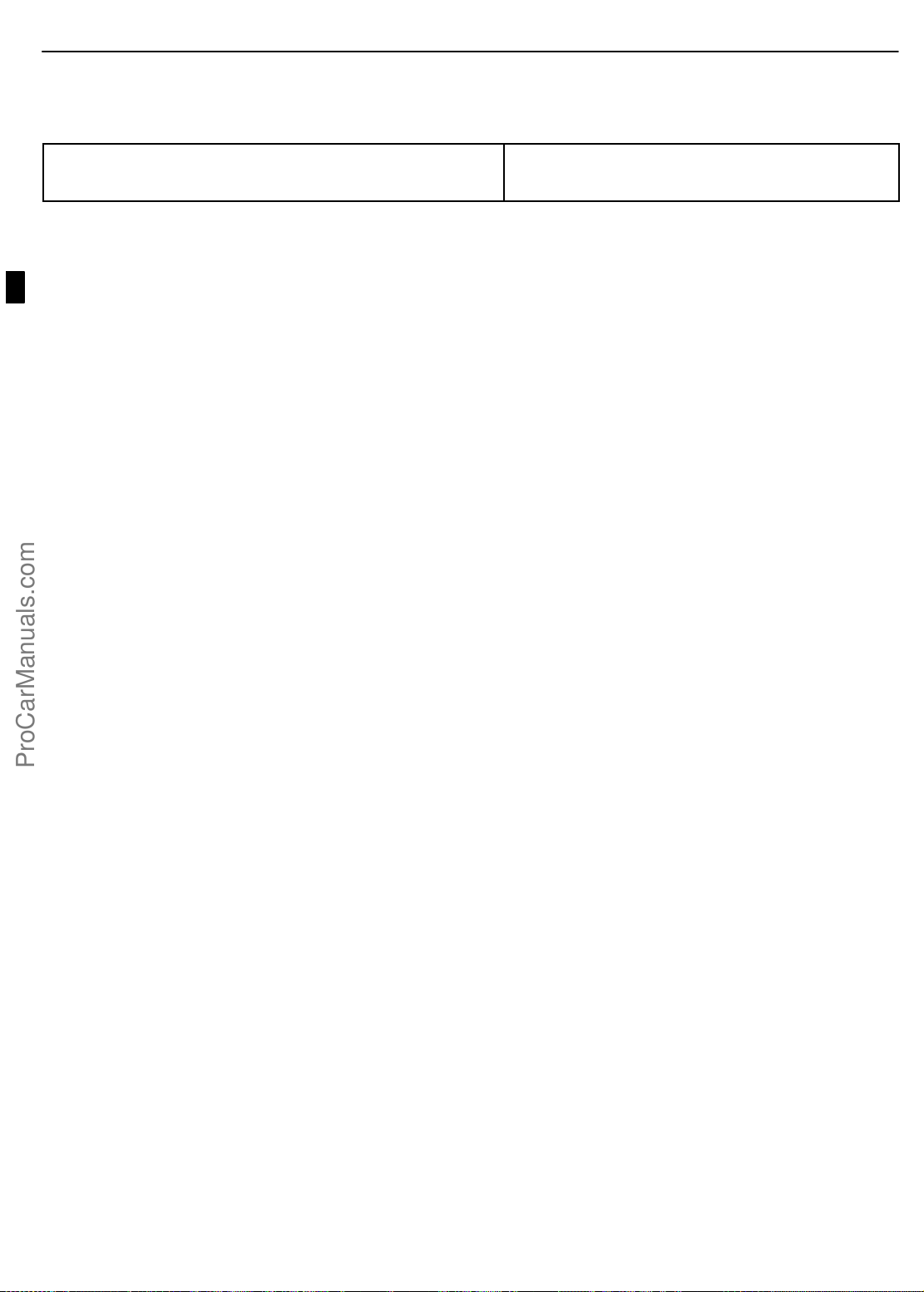
03−8
−SERVICE SPECIFICATIONS LUBRICATION
LUBRICATION
SERVICE DATA
Oil pump
Tip clearance Standard
Body clearance Standard
031H5−03
0.08 to 0.20 mm (0.0031 to 0.0079 in.)
0.10 to 0.20 mm (0.0039 to 0.0079 in.)
1CD−FTV ENGINE REPAIR MANUAL (RM1046E)
Page 31
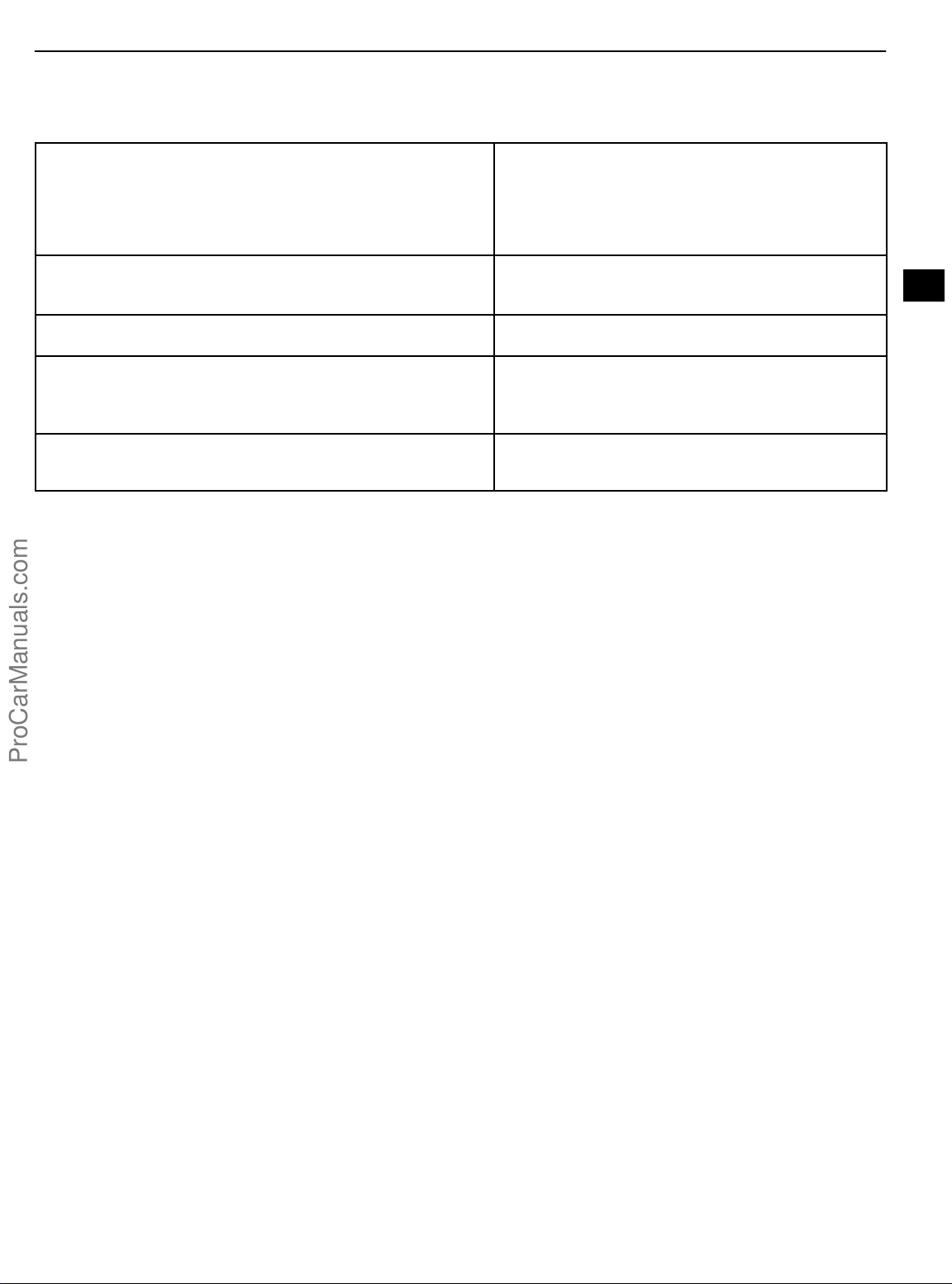
−SERVICE SPECIFICATIONS STARTING & CHARGING
03−9
STARTING & CHARGING
SERVICE DATA
Starter armature assy
Circle runout Maximum
Diameter Standard
Minimum
Undercut depth Standard
Minimum
Brush
Brush lenght Standard
Minimum
Starter brush holder assy
Spring installed load Standard
Generator rotor assy
Rotor coil resistance at 20_C (68_F)
Slip ring diameter Standard
Minimum
Generator brush holder assy
Brush exposed lenght Standard
Minimum
031E6−04
0.05 mm (0.0020 in.)
35.0 mm (1.378 in.)
34.0 mm (1.339 in.)
0.6 mm (0.024 in.)
0.2 mm (0.008 in.)
15.5 mm (0.610 in.)
10.0 mm (0.394 in.)
23.5 to 29.5 N (2.4 to 3.0 kgf, 5.3 to 6.6 lbf)
2.3 to 2.7 W
14.2 to 14.4 mm (0.559 to 0.567 in.)
14.0 mm (0.551 in.)
10.5 mm (0.413 in.)
4.5 mm (0.177 in.)
1CD−FTV ENGINE REPAIR MANUAL (RM1046E)
Page 32
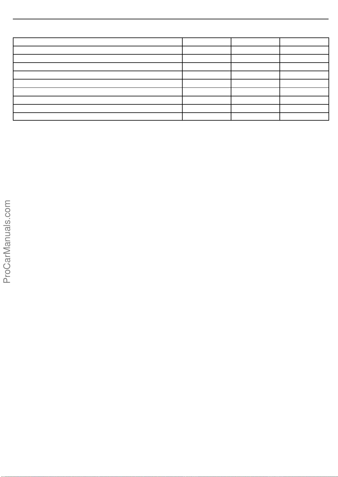
03−10
TORQUE SPECIFICATION
−SERVICE SPECIFICATIONS STARTING & CHARGING
031E7−05
Part Tightened
Starter commutator end frame assy x Starter brush holder assy 3.8 39 33 in.×lbf
Starter drive housing assy x Starter commutator end frame assy 6.0 61 53 in.×lbf
Magnetic switch x Starter drive housing assy 2.3 23 20 in.×lbf
Magnetic switch x Lead wire 5.9 60 52 in.×lbf
Generator drive end frame assy x Retainer plate 2.3 23 20 in.×lbf
Generator coil assy x Generator drive end frame assy 5.8 59 51 in.×lbf
Generator brush holder assy x Generator coil assy 1.8 18 16 in.×lbf
Generator rear end cover x Generator coil assy 4.6 47 41 in.×lbf
Generator w/clutch pulley x Generator rotor assy 111 1,132 82
N×m kgf×cm ft×lbf
1CD−FTV ENGINE REPAIR MANUAL (RM1046E)
Page 33
−INTAKE TURBOCHARGER SUB−ASSY (1CD−FTV)(From
September, 2003)
13−1
TURBOCHARGER SUB−ASSY (1CD−FTV)(From September,
2003)
1308O−01
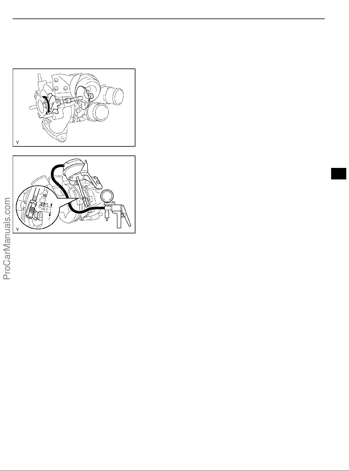
INSPECTION
1. INSPECT TURBINE SHAFT
(a) Check the operation.
(1) Grasp the edge of the turbine shaft, then turn it.
Turn
A86433
A86434
If the turbine shaft does not turn or it turns with heavy drag, replace the turbocharger.
2. INSPECT ACTUATOR OPERATION
(a) Apply vacuum of 66 kPa (500 mmHg, 20 in.Hg), then raise
(b) Lower the vacuum, then check the stroke when the vacu-
If the operation is not as specified, replace the turbocharger.
Check that the turbine shaft turns smoothly.
the actuator push rod.
um is at the following values.
Standard stroke:
50 kPa (375 mmHg, 15 in.Hg): 0.2 mm (0.008 in.)
30 kPa (225 mmHg, 9 in.Hg): 5.0 mm (0.197 in.)
1CD−FTV ENGINE REPAIR MANUAL (RM1046E)
Page 34
−ENGINE MECHANICAL PARTIAL ENGINE ASSY (1CD−FTV)(From September,
2003)
14−1
PARTIAL ENGINE ASSY (1CD−FTV)(From September, 2003)
141NP−01
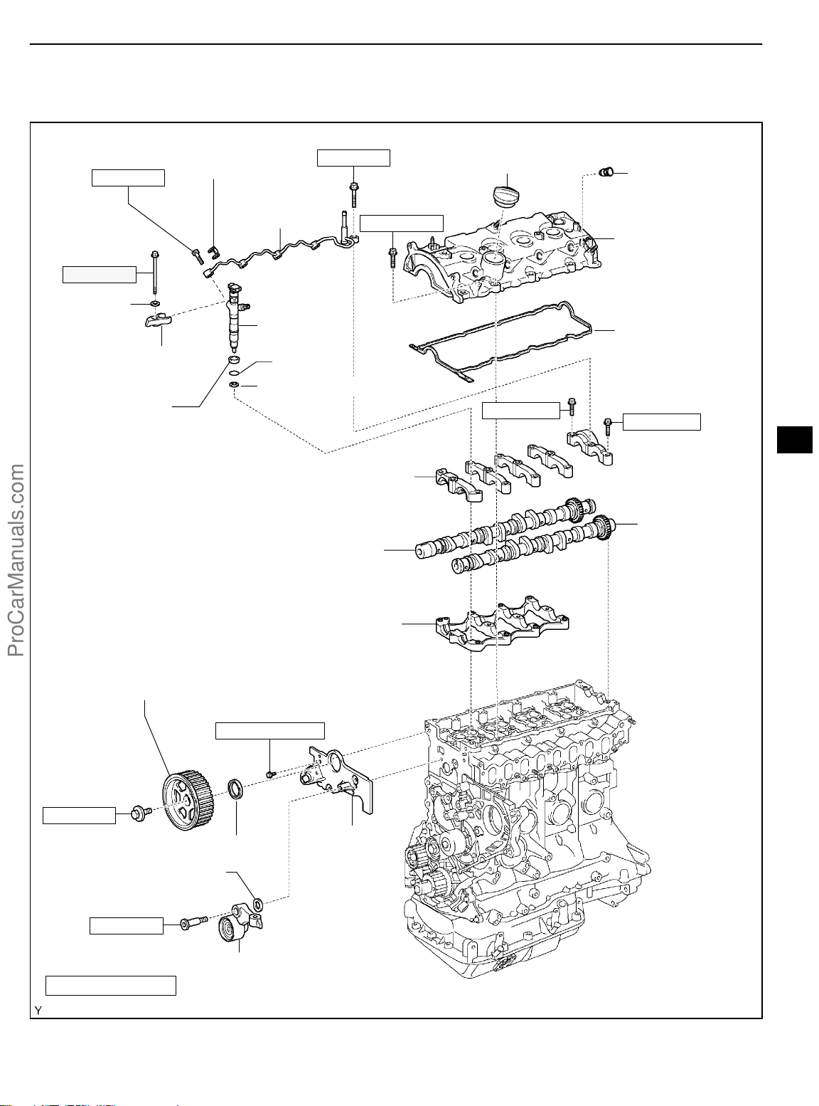
COMPONENTS
18 (184, 13)
27 (275, 20)
Washer
Nozzle Holder Clamp
z Fuel Injector
Back−up
Ring No. 1
z Gasket
20 (204, 15)
Nozzle Leakage
Pipe Assy
Injector Assy
z O−ring
z Injection Nozzle Seat
Camshaft Bearing Cap
Oil Filler Cap Sub−assy
13 (135, 10)
20 (204, 15)
z Nozzle Holder
Seal
Cylinder Head
Cover Sub−assy
Gasket
20 (204, 15)
x5
Camshaft Timing Pulley
88 (899, 65)
z Oil Seal
Plate Washer
35 (357, 26)
Camshaft
Sub−assy No. 2
Camshaft Carrier
8.8 (90, 78 in.·lbf)
x4
Camshaft
Sub−assy No. 1
Camshaft Oil
Seal Retainer
Timing Belt Idler Sub−assy No. 1
N·m (kgf·cm, ft·lbf)
: Specified torque
z Non−reusable part
1CD−FTV ENGINE REPAIR MANUAL (RM1046E)
A85930
Page 35
14−2
−ENGINE MECHANICAL PARTIAL ENGINE ASSY (1CD−FTV)(From September,
2003)
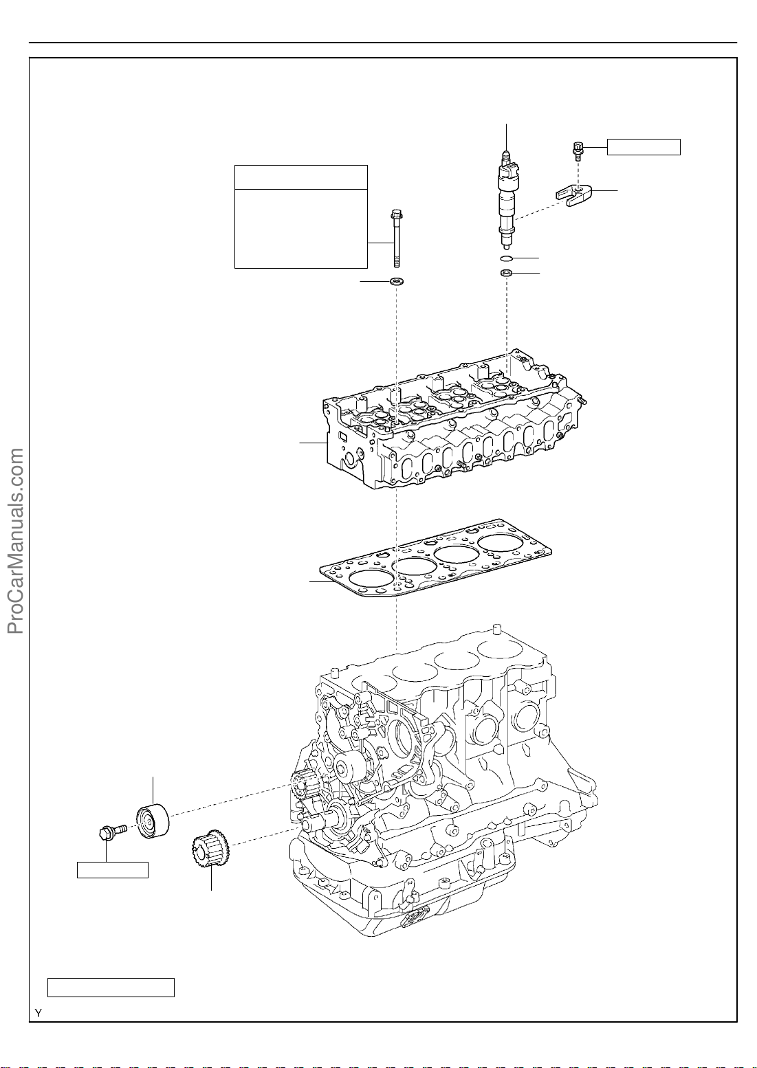
Exhaust Fuel Addition Injector Assy
12 (117, 8.5)
See page 14−4
1st 45 (460, 33)
2nd Turn 90_
3rd Turn 90_
4th Turn 90_
Plate Washer
Cylinder Head Sub−assy
Nozzle Holder
Clamp
x18
z O−ring
z Gasket
z Cylinder Head Gasket
Timing Belt Idler Sub−assy No. 2
47 (475, 34)
Crankshaft Timing Pulley
N·m (kgf·cm, ft·lbf)
: Specified torque
z Non−reusable part
1CD−FTV ENGINE REPAIR MANUAL (RM1046E)
A85931
Page 36
−ENGINE MECHANICAL PARTIAL ENGINE ASSY (1CD−FTV)(From September,
2003)
14−3
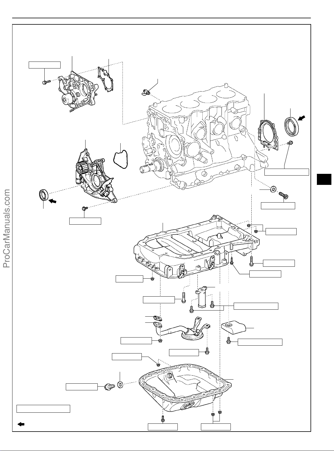
Water Pump Assy
31 (320, 23)
x7
z Oil Seal
z Gasket
Oil Pump Assy
x9
31 (320, 23)
z Gasket
Cylinder Block Water
Drain Cock Sub−assy
Oil Pan Sub−assy
Engine Rear Oil
Seal Retainer
z Oil Seal
x6
7.4 (75, 65 in.·lbf)
z Gasket
33 (331, 24)
Oil Check Valve
Sub−assy
Drain Plug
34 (350, 25)
11 (112, 8)
z Gasket
Oil Strainer Sub−assy
13 (133, 10 )
12 (119, 9)
z Gasket
42 (428, 31)
x2
x6
21 (209, 15)
x2
x6
x6
11 (112, 8)
Oil Regulator Assy
9.0 (92, 80 in.·lbf)
Oil Pan Insulator
7.5 (77, 66 in.·lbf)
Oil Pan Sub−assy No. 2
11 (112, 8)
21 (214, 15)
N·m (kgf·cm, ft·lbf)
: Specified torque
z Non−reusable part
Apply MP grease
1CD−FTV ENGINE REPAIR MANUAL (RM1046E)
x16
12 (119, 9)
12 (119, 9)
A85932
Page 37
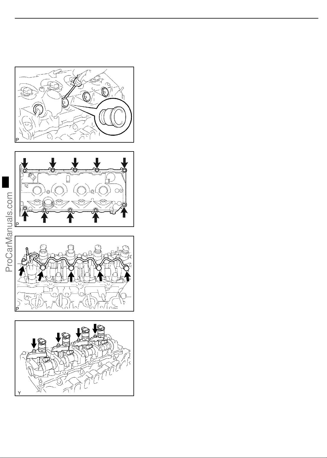
14−4
OVERHAUL
1. REMOVE OIL FILLER CAP SUB−ASSY
2. REMOVE NOZZLE HOLDER SEAL
(a) Using a screwdriver, pry out the 4 nozzle holder seals.
A85935
3. REMOVE CYLINDER HEAD COVER SUB−ASSY
(a) Remove the 10 bolts, cylinder head cover and gasket.
−ENGINE MECHANICAL PARTIAL ENGINE ASSY (1CD−FTV)(From September,
2003)
141NQ−01
A85933
4. REMOVE NOZZLE LEAKAGE PIPE ASSY
(a) Remove the 4 hollow screws and bolt.
(b) Remove the nozzle leakage pipe and 4 gaskets from the
cylinder head and injector.
A85934
5. REMOVE NOZZLE HOLDER CLAMP
(a) Remove the 4 bolts, 4 washers and 4 nozzle holder
clamps.
A87963
1CD−FTV ENGINE REPAIR MANUAL (RM1046E)
Page 38
A87964
−ENGINE MECHANICAL PARTIAL ENGINE ASSY (1CD−FTV)(From September,
2003)
14−5
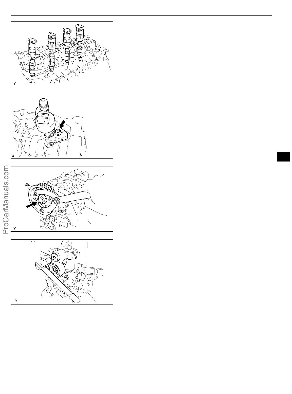
6. REMOVE INJECTOR ASSY
(a) Remove the 4 injectors from the cylinder head.
HINT:
Arrange the injectors in the correct order.
7. REMOVE EXHAUST FUEL ADDITION INJECTOR
ASSY
(a) Using a Torx socket wrench (T40), remove the Torx screw.
(b) Remove the nozzle holder clamp, addition injector and
gasket.
SST
8mm
Hexagon
Wrench
A85925
8. REMOVE CAMSHAFT TIMING PULLEY
(a) Using SST, remove the pulley bolt.
SST 09960−10010 (09962−01000, 09963−01000)
(b) Remove the timing pulley.
HINT:
Using a plastic−faced hammer, tap out the pulley.
(c) Remove the set key.
A62592
9. REMOVE TIMING BELT IDLER SUB−ASSY NO.1
(a) Using an 8 mm hexagon wrench, remove the idler pulley
shaft, idler pulley and plate washer.
A57095
10. REMOVE TIMING BELT IDLER SUB−ASSY NO.2
1CD−FTV ENGINE REPAIR MANUAL (RM1046E)
Page 39
14−6
SST
A57096
−ENGINE MECHANICAL PARTIAL ENGINE ASSY (1CD−FTV)(From September,
2003)
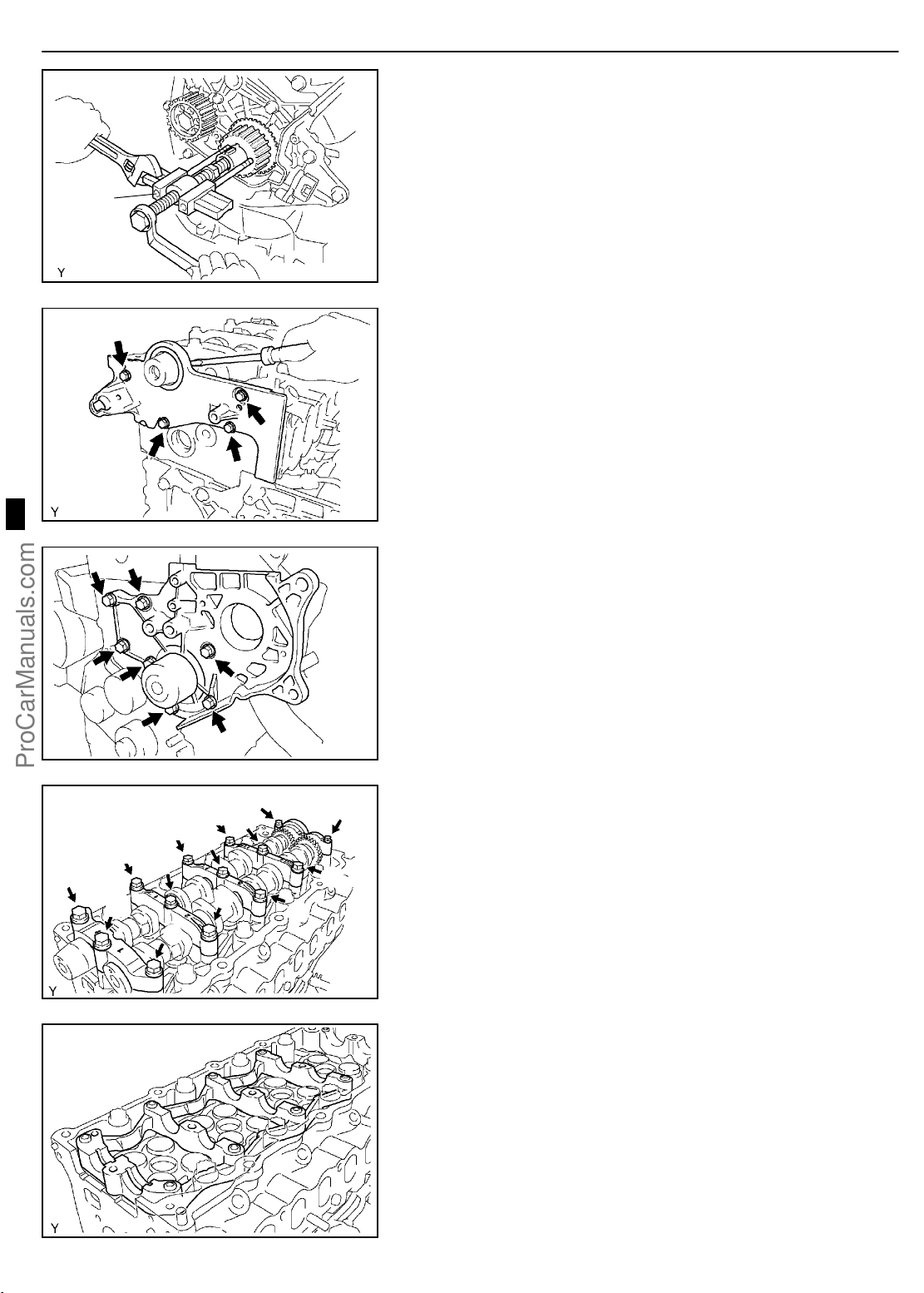
11. REMOVE CRANKSHAFT TIMING PULLEY
(a) If the timing pulley cannot be removed by hand, use SST
to remove the pulley.
SST 09950−50013 (09951−05010, 09952−05010,
09953−05010, 09953−05020, 09954−05021)
12. REMOVE CAMSHAFT OIL SEAL RETAINER
(a) Remove the 4 bolts.
(b) Using a screwdriver, remove the oil seal retainer by prying
between the oil seal retainer and camshaft bearing cap.
10
13
7
2
8
3
1
11
14
6
A57097
13. REMOVE WATER PUMP ASSY
(a) Remove the 7 bolts, water pump and gasket.
A87943
5
14. REMOVE CAMSHAFT
4
(a) Using several steps, loosen and remove the 14 bearing
cap bolts uniformly in the sequence shown in the illustra-
9
12
A87965
tion.
(b) Remove the 5 bearing caps and camshaft sub−assembly.
A09624
1CD−FTV ENGINE REPAIR MANUAL (RM1046E)
15. REMOVE NO.2 CAMSHAFT
(a) Remove the camshaft sub−assembly and camshaft carri-
er.
Page 40
−ENGINE MECHANICAL PARTIAL ENGINE ASSY (1CD−FTV)(From September,
2003)
14−7
16
8
2
4
67
Pry
1712
14 15
5
11101318
3
1
9
A09566
A09563
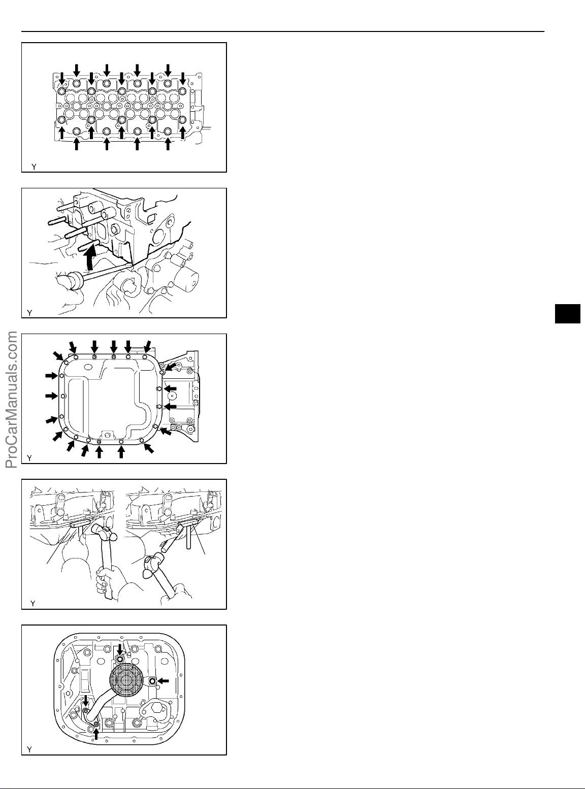
16. REMOVE CYLINDER HEAD SUB−ASSY
(a) Using several steps, loosen the 18 cylinder head bolts
uniformly in the sequence shown in the illustration. Remove the 18 cylinder head bolts and plate washers.
NOTICE:
Removing the bolts in a wrong order could cause warpage
or cracks of the cylinder head.
(b) Lift the cylinder head from the dowels on the cylinder
block, then place the cylinder head on wooden blocks on
a work bench.
HINT:
To lift the cylinder head, pry between the cylinder head and cylinder block using a screwdriver.
NOTICE:
Be careful not to damage the contact surfaces of the cylinder head and cylinder block.
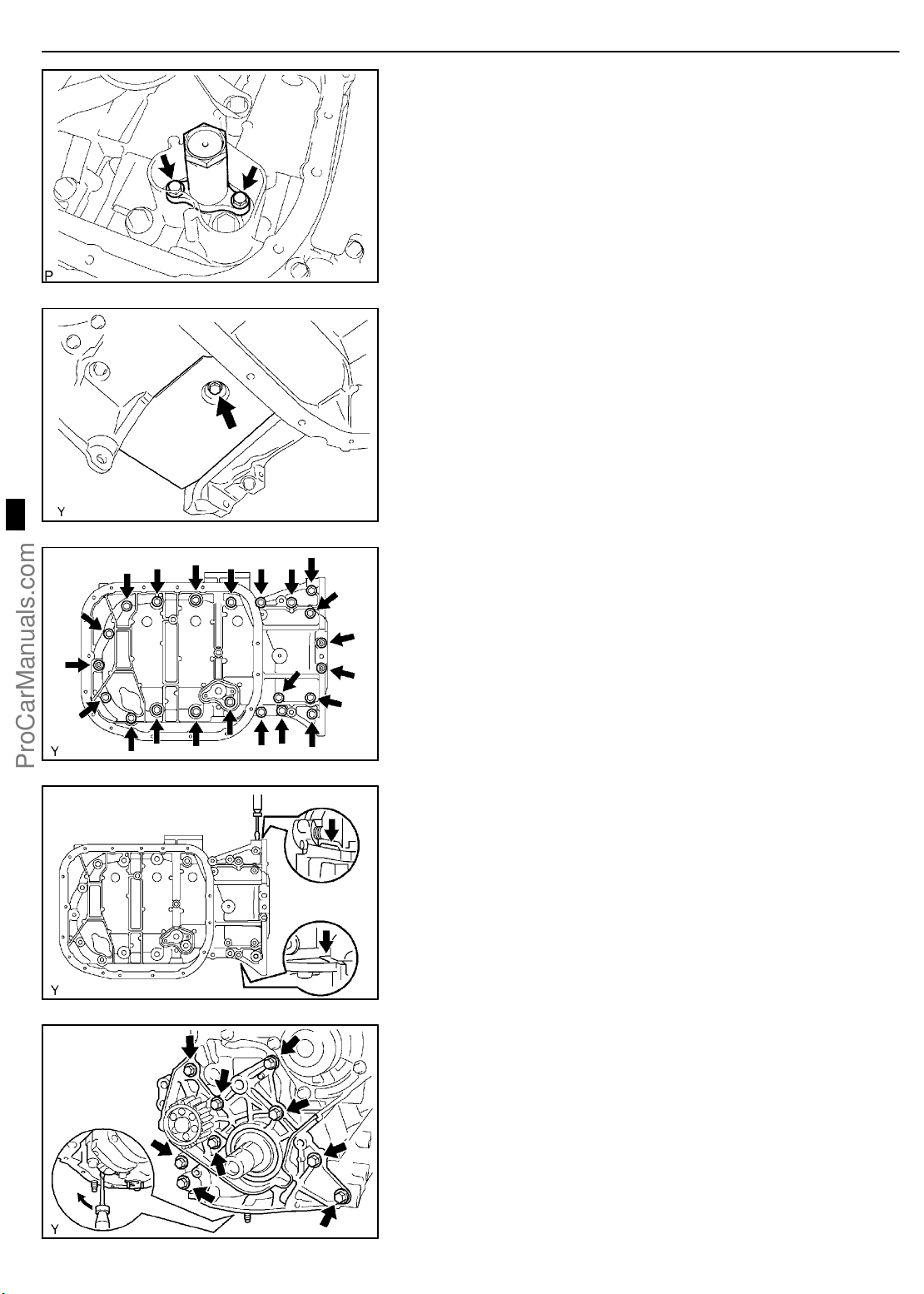
17. REMOVE OIL PAN SUB−ASSY NO.2
(a) Remove the 16 bolts and 3 nuts.
SST
A56695
SST
B08601
A56696
(b) Insert the blade of SST between the No. 1 and No. 2 oil
pans, then cut off the applied sealer and remove the No.
2 oil pan.
SST 09032−00100
NOTICE:
Be careful not to damage the No. 1 and No. 2 oil pans.
18. REMOVE OIL STRAINER SUB−ASSY
(a) Remove the 2 bolts and 2 nuts, then remove the oil strain-
er and gasket.
1CD−FTV ENGINE REPAIR MANUAL (RM1046E)
Page 41
14−8
A85936
−ENGINE MECHANICAL PARTIAL ENGINE ASSY (1CD−FTV)(From September,
2003)
19. REMOVE OIL REGULATOR ASSY
(a) Remove the 2 bolts and oil regulator.
20. REMOVE OIL PAN INSULATOR
(a) Remove the bolt and oil pan insulator.
B08009
21. REMOVE OIL PAN SUB−ASSY
(a) Remove the 19 bolts and 3 nuts.
A56697
(b) Using a screwdriver, remove the oil pan by prying be-
tween the cylinder block and No. 1 oil pan.
NOTICE:
Be careful not to damage the cylinder block and No. 1 oil
pan.
A56698
A56699
1CD−FTV ENGINE REPAIR MANUAL (RM1046E)
22. REMOVE OIL PUMP ASSY
(a) Remove the 9 bolts.
(b) Remove the oil pump by prying between the oil pump and
main bearing cap using a screwdriver.
(c) Remove the gasket.
Page 42
8mm
Hexagon
Wrench
A09518
−ENGINE MECHANICAL PARTIAL ENGINE ASSY (1CD−FTV)(From September,
2003)
14−9
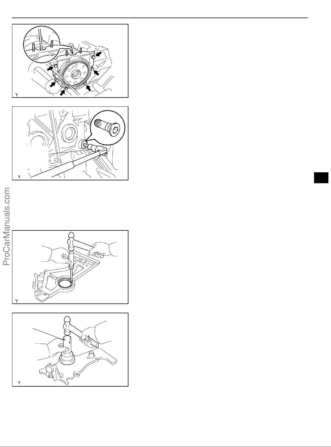
23. REMOVE ENGINE REAR OIL SEAL RETAINER
(a) Remove the 6 bolts.
(b) Using a screwdriver, remove the oil seal retainer by prying
between the oil seal retainer and main bearing cap.
NOTICE:
Be careful not to damage the oil seal retainer and main
bearing cap.
24. REMOVE OIL CHECK VALVE SUB−ASSY
(a) Using an 8 mm hexagon wrench, remove the check valve
and gasket.
A09519
25. REMOVE CYLINDER BLOCK WATER DRAIN COCK SUB−ASSY
26. REMOVE CAMSHAFT OIL SEAL
(a) Using a screwdriver and hammer, tap out the oil seal.
A09619
27. INSTALL CAMSHAFT OIL SEAL
SST
(a) Using SST and a hammer, tap in a new oil seal until its sur-
face is flush with the camshaft oil seal retainer edge.
SST 09223−46011
(b) Apply multipurpose grease to a new oil seal lip.
NOTICE:
Keep the lip free of foreign objects.
A09620
1CD−FTV ENGINE REPAIR MANUAL (RM1046E)
Page 43
14−10
SST
B07976
−ENGINE MECHANICAL PARTIAL ENGINE ASSY (1CD−FTV)(From September,
2003)
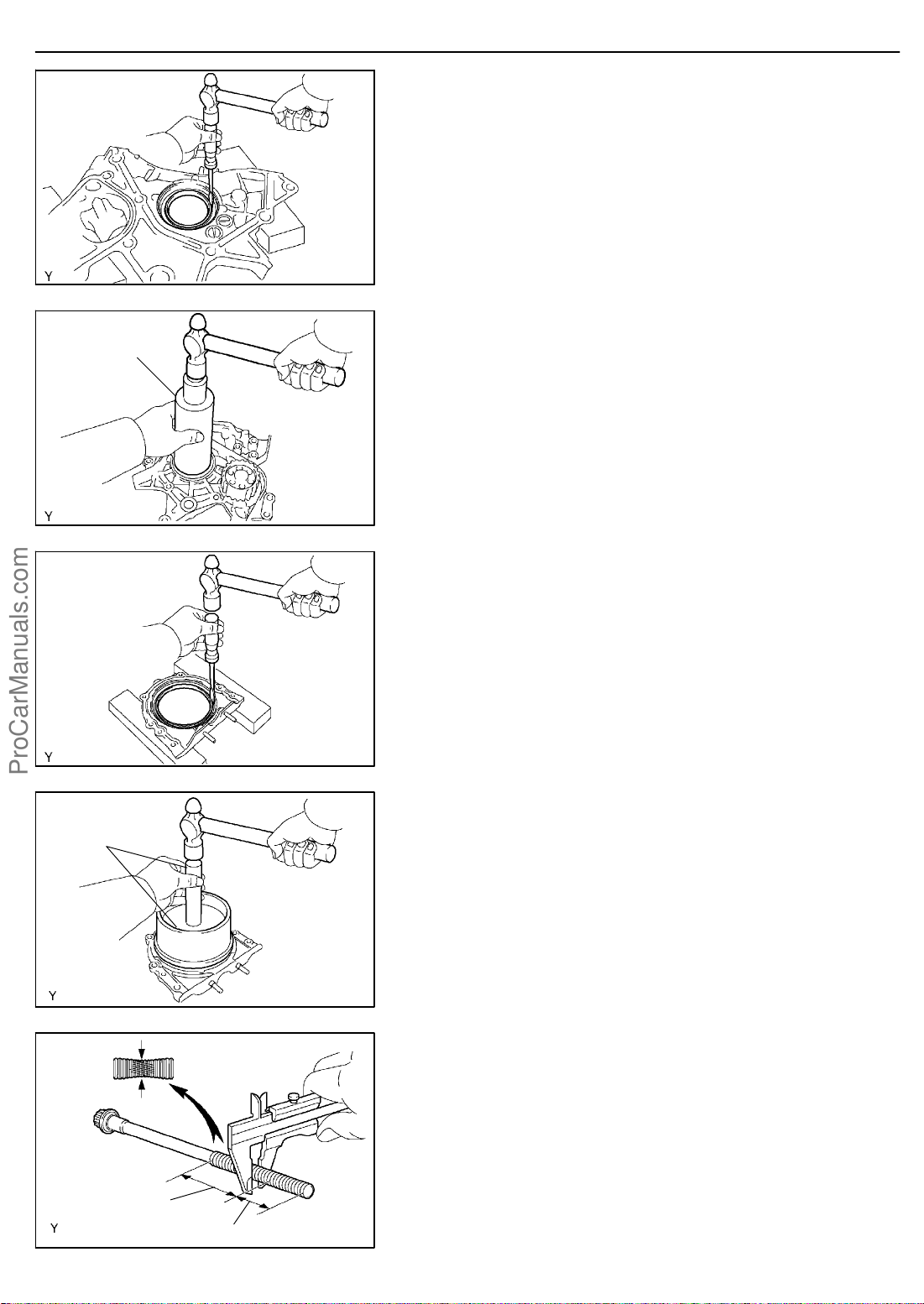
28. REMOVE CRANKSHAFT SEAL
(a) Using a screwdriver and hammer, tap out the oil seal.
29. INSTALL CRANKSHAFT SEAL
(a) Using SST and a hammer, tap in a new oil seal until its sur-
face is flush with the oil pump edge.
SST 09316−60011 (09316−00011, 09316−00021)
(b) Apply multipurpose grease to a new oil seal lip.
NOTICE:
Keep the lip free of foreign objects.
SST
A56700
30. REMOVE ENGINE REAR OIL SEAL
(a) Using a screwdriver and hammer, tap out the oil seal.
A09449
31. INSTALL ENGINE REAR OIL SEAL
(a) Using SST and a hammer, tap in a new oil seal until its sur-
face is flush with the rear oil seal retainer edge.
SST 09223−15030, 09950−70010 (09951−07100)
(b) Apply multipurpose grease to a new oil seal lip.
NOTICE:
Keep the lip free of foreign objects.
A09451
Measuring Point
16 mm (0.63 in.)
1CD−FTV ENGINE REPAIR MANUAL (RM1046E)
A09555
32. INSPECT CYLINDER HEAD SET BOLT
(a) Using vernier calipers, measure the tension portion diam-
eter of the bolt.
Standard outside diameter:
10.40 to 11.00 mm (0.4094 to 0.4331 in.)
If the diameter is less than minimum, replace the bolt.
Page 44
−ENGINE MECHANICAL PARTIAL ENGINE ASSY (1CD−FTV)(From September,
2003)
14−11
Upper
Front
Seal Packing
60_
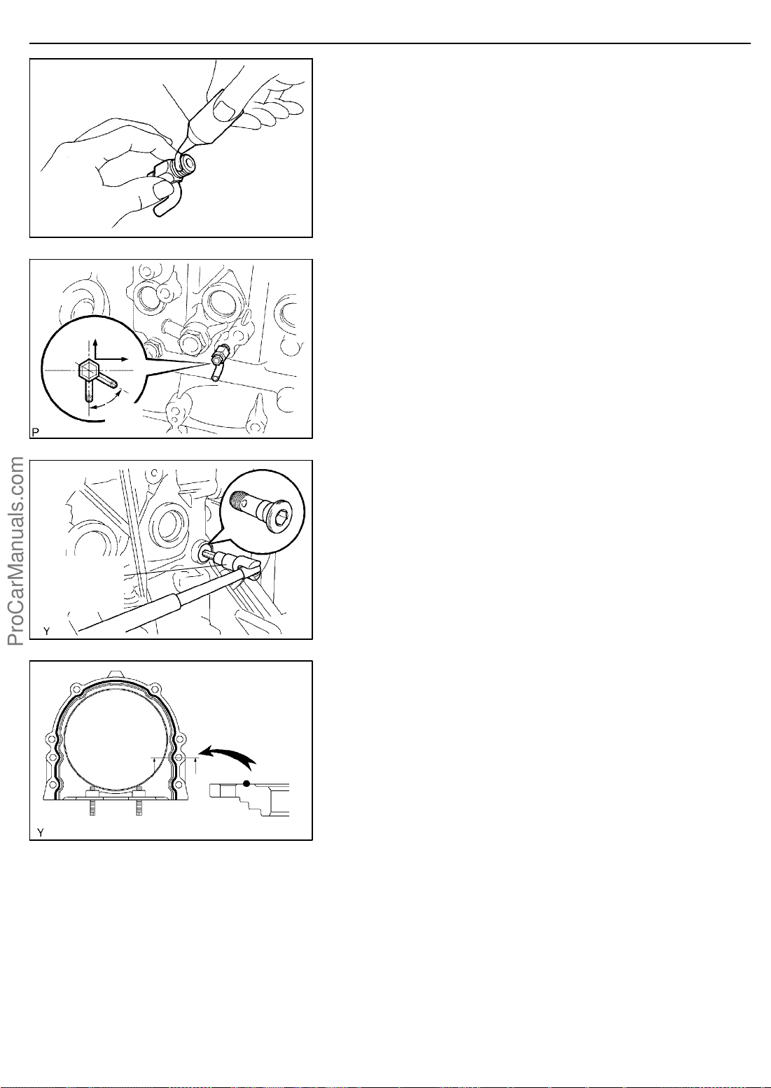
33. INSTALL CYLINDER BLOCK WATER DRAIN COCK
SUB−ASSY
(a) Apply seal packing to the 2 or 3 threads.
Seal packing: Part No. 08826−00100 or equivalent
P12477
(b) Install the drain union.
Torque: 29 N×m (291 kgf×cm, 21 ft×lbf)
HINT:
After applying the specified torque, if the drain pipe of the drain
union is not located as shown in the illustration, rotate the drain
union further clockwise so the drain pipe faces downward.
A85937
34. INSTALL OIL CHECK VALVE SUB−ASSY
(a) Using an 8 mm hexagon wrench, install a new gasket and
the check valve.
Torque: 33 N×m (331 kgf×cm, 24 ft×lbf)
8mm
Hexagon
Wrench
Seal Width
2to4mm
(0.08 to 0.16 in.)
A09519
A09476
35. INSTALL ENGINE REAR OIL SEAL RETAINER
(a) Apply seal packing to the oil seal retainer as shown in the
illustration.
Seal packing: Part No. 08826−00080 or equivalent
NOTICE:
S Install a nozzle of which opening is cut to 2 to 4 mm
(0.08 to 0.16 in.).
S The parts must be set within 3 minutes and must be
assembled within 15 minutes after applying seal
packing. Otherwise the material must be removed
and reapplied.
S Immediately remove the nozzle from the tube, then re-
install the cap.
(b) Install the oil seal retainer with the 6 bolts. Tighten the
bolts uniformly in several steps.
Torque: 7.4 N×m (75 kgf×cm, 65 in.×lbf)
1CD−FTV ENGINE REPAIR MANUAL (RM1046E)
Page 45
14−12
−ENGINE MECHANICAL PARTIAL ENGINE ASSY (1CD−FTV)(From September,
2003)
Seal Width
2to4mm
(0.08 to 0.16 in.)
Seal
Packing
New Gasket
A56701
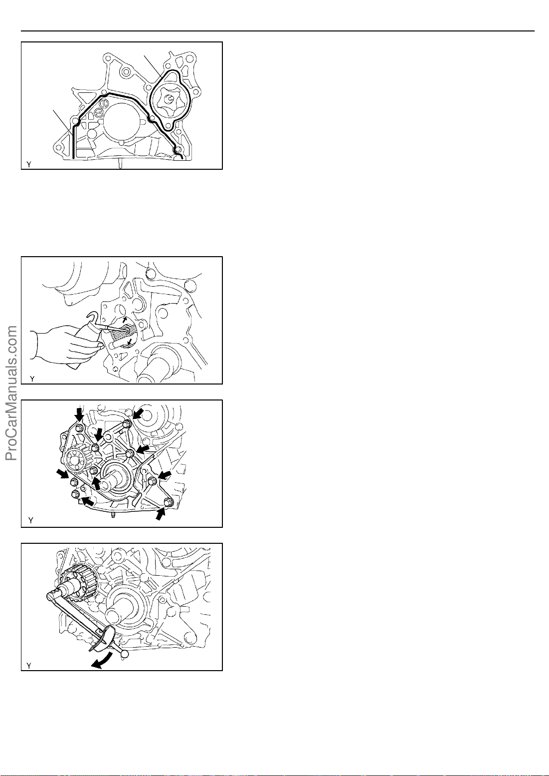
36. INSTALL OIL PUMP ASSY
(a) Apply seal packing to the oil pump as shown in the illustra-
tion.
Seal packing: Part No. 08826−00080 or equivalent
NOTICE:
S Avoid applying an excessive amount to the surface.
S Install a nozzle of which opening is cut to 2 to 4 mm
(0.08 to 0.16 in.).
S The parts must be set within 3 minutes and must be
assembled within 15 minutes after applying seal
packing. Otherwise the material must be removed
and reapplied.
S Immediately remove the nozzle from the tube, then re-
install the cap.
(b) Install a new gasket to the oil pump.
(c) Pour 0.5 cm3(0.03 cu in.) or more of engine oil into the
bushing of the cylinder block.
(d) Apply engine oil to the cylinder block side which contacts
the oil pump driven rotor.
B08024
(e) Install the oil pump with the 9 bolts.
Torque: 31 N×m (320 kgf×cm, 23 ft×lbf)
A57099
(f) Measure the oil pump rotating torque.
(1) Check that the pump rotates smoothly without mak-
ing a noise.
(2) Using a torque wrench, check the pump rotating
torque.
Rotating torque: 3.0 N×m (31 kgf×cm, 27 in.×lbf) or less
A56702
1CD−FTV ENGINE REPAIR MANUAL (RM1046E)
Page 46
−ENGINE MECHANICAL PARTIAL ENGINE ASSY (1CD−FTV)(From September,
2003)
14−13
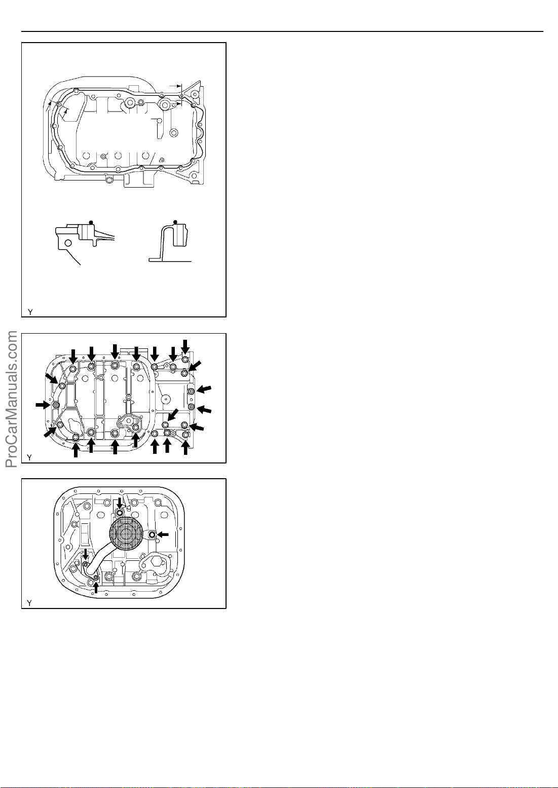
37. INSTALL OIL PAN SUB−ASSY
(a) Apply seal packing to the No. 1 oil pan as shown in the
B
illustration.
Seal packing: Part No. 08826−00080 or equivalent
A
Seal Width
4to7mm
(0.16 to 0.28 in.)
NOTICE:
S Install a nozzle of which opening is cut to 4 to 7 mm
(0.16 to 0.28 in.).
S The parts must be set within 3 minutes and must be
assembled within 15 minutes after applying seal
packing. Otherwise the material must be removed
and reapplied.
BA
S Immediately remove the nozzle from the tube, then re-
install the cap.
A
A
B
B
D
B
B
A
A
C
A
A
A56703
C
CB
C
D
C
C
B
D
C
A56697
A56696
(b) Install the oil pan with 19 bolts and 3 nuts.
Torque:
42 N×m (428 kgf×cm, 31 ft×lbf) for bolt A
21 N×m (209 kgf×cm, 15 ft×lbf) for bolt B
11 N×m (112 kgf×cm, 8 ft×lbf) for bolt C
11 N×m (112 kgf×cm, 8 ft×lbf) for nut D
38. INSTALL OIL REGULATOR ASSY
Torque: 9.0 N×m (92 kgf×cm, 80 in.×lbf)
39. INSTALL OIL STRAINER SUB−ASSY
(a) Install a new gasket and the oil strainer with the 2 bolts
and 2 nuts.
Torque:
21 N×m (209 kgf×cm, 15 ft×lbf) for bolt
13 N×m (135 kgf×cm, 10 ft×lbf) for nut
1CD−FTV ENGINE REPAIR MANUAL (RM1046E)
Page 47
14−14
A
Seal Width
4to7mm
(0.16 to 0.28 in.)
−ENGINE MECHANICAL PARTIAL ENGINE ASSY (1CD−FTV)(From September,
2003)
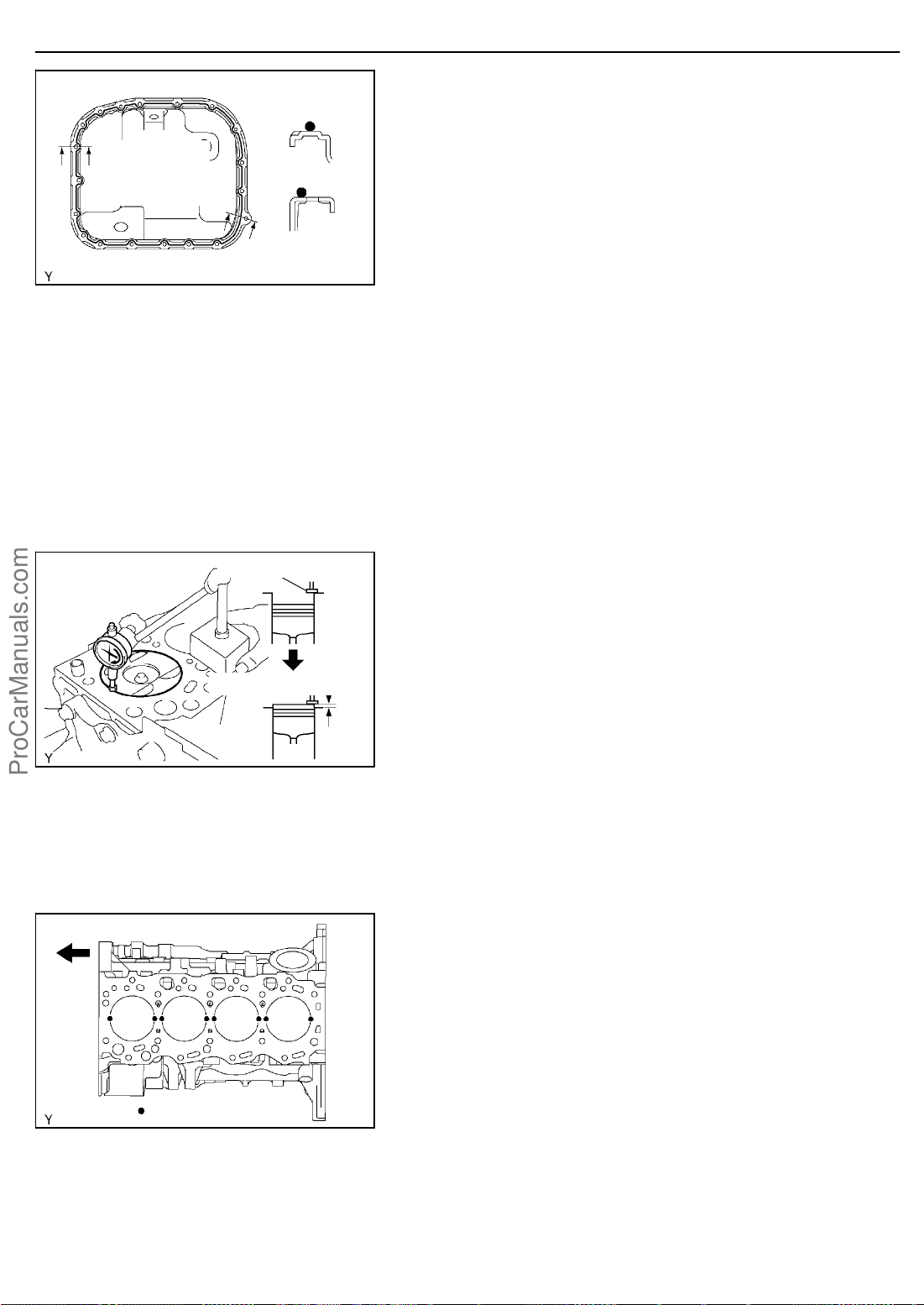
40. INSTALL OIL PAN SUB−ASSY NO.2
A
(a) Apply seal packing to the oil pan as shown in the illustra-
tion.
Seal packing: Part No. 08826−00080 or equivalent
B
B
NOTICE:
S Install a nozzle of which opening is cut to 4 to 7 mm
(0.16 to 0.28 in.).
S The parts must be set within 3 minutes and must be
A56704
assembled within 15 minutes after applying seal
packing. Otherwise the material must be removed
and reapplied.
S Immediately remove the nozzle from the tube, then re-
install the cap.
(b) Install the oil pan with the 16 bolts and 3 nuts. Tighten the
bolts and nuts uniformly in several steps.
Torque: 12 N×m (119 kgf×cm, 9 ft×lbf)
Measuring Tip
Protrusion Height
Front
A57100
41. INSTALL CYLINDER HEAD SUB−ASSY
(a) Measure the protrusion height of the piston heads.
(1) Clean the cylinder block with solvent.
(2) Set the piston to measure to slightly before the
TDC.
(3) Place a dial indicator on the cylinder block, then cali-
brate the dial indicator at 0 mm (0 in.).
HINT:
S Place the measuring tip of the dial indicator as shown in
the illustration.
S Make sure that the measuring tip is square to the cylinder
block gasket and piston head when measuring.
(4) Find the most overhung position of the piston head
by slowly turning the crankshaft clockwise and
counterclockwise.
(5) Measure the protrusion height of the piston head for
each cylinder at 2 places as shown in the illustration. (Total of 8 measurements.)
(6) Record the higher protrusion height of the 2 mea-
surements at each cylinder.
Measuring Point
1CD−FTV ENGINE REPAIR MANUAL (RM1046E)
A56706
Page 48
−ENGINE MECHANICAL PARTIAL ENGINE ASSY (1CD−FTV)(From September,
2003)
14−15
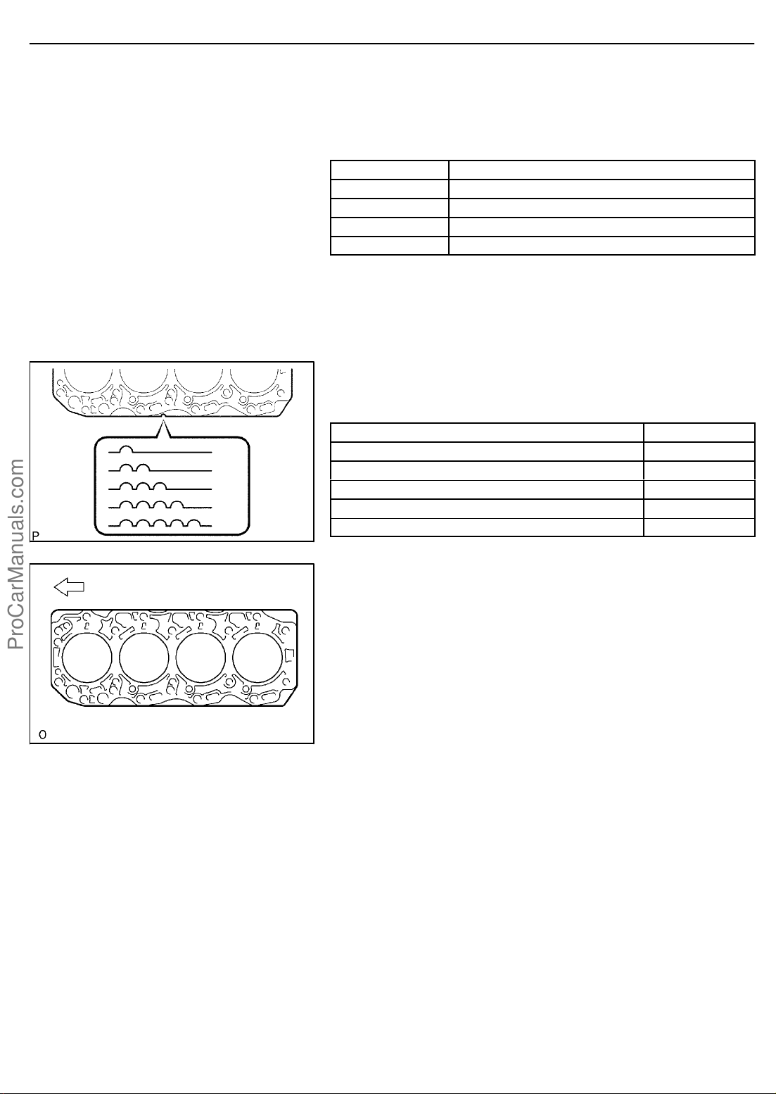
(b) Select a new cylinder head gasket.
HINT:
There are 5 sizes of new cylinder head gaskets, marked ”A”,
”B”, ”C”, ”D”, and ”E”.
New cylinder head gasket thickness:
A
B 0.90 to 1.00 mm (0.0354 to 0.0394 in.)
C 0.95 to 1.05 mm (0.0374 to 0.0413 in.)
D 1.00 to 1.10 mm (0.0394 to 0.0433 in.)
E 1.05 to 1.15 mm (0.0413 to 0.0453 in.)
0.85 to 0.95 mm (0.0335 to 0.0374 in.)
(1) Find the highest protrusion height among the 4
measurement records. It is used to select a new cylinder head gasket.
(2) Select a new gasket among A to E using the matrix
below.
New gasket matrix:
Piston Protrusion mm (in.)
A
B
C
D
E
A80117
0.165 to 0.220 (0.0065 to 0.0087) A
0.220 to 0.270 (0.0087 to 0.0106) B
0.270 to 0.320 (0.0106 to 0.0126) C
0.320 to 0.370 (0.0126 to 0.0146) D
0.370 to 0.425 (0.0146 to 0.0167) E
Gasket Size
Front
(c) Place the selected new cylinder head gasket on the cylin-
der block.
NOTICE:
Pay attention to the mounting orientation.
(d) Place the cylinder head in position on the cylinder head
gasket.
A90797
1CD−FTV ENGINE REPAIR MANUAL (RM1046E)
Page 49
14−16
(A)
(B) (B) (B) (B)
11
15
(A) (A) (A) (A)
(B)
7
(A)
3
1
(A)(A)
14
6
10
45
1617
89
182
1213
(B)(B)(B)(B)(B)
A09564
−ENGINE MECHANICAL PARTIAL ENGINE ASSY (1CD−FTV)(From September,
2003)
(e) Install the cylinder head bolts.
HINT:
S The cylinder head bolts are tightened in 4 successive
steps (steps (3), (5), (6) and (7)).
S If the cylinder head bolt is broken or deformed, replace it
with a new bolt.
(1) Apply a light coat of engine oil to the threads of the
cylinder head bolts and plate washers.
(2) Install the plate washer to the cylinder head bolt.
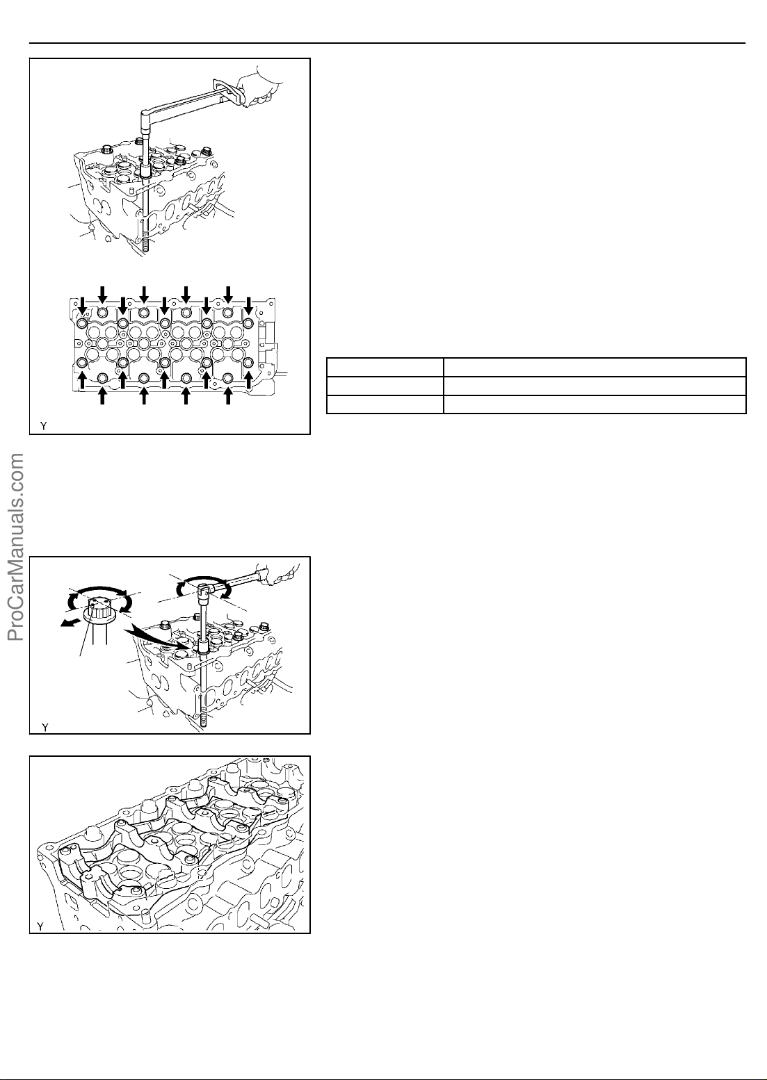
(3) Using several steps, install and tighten the 18 cylin-
der head bolts uniformly in the sequence shown in
the illustration.
Torque: 45 N×m (459 kgf×cm, 33 ft×lbf)
HINT:
See the table below for the bolt length.
Bolt Type
(A) 160 mm (6.30 in.)
(B) 104 mm (4.09 in.)
Bolt Length
If the cylinder head bolt does not meet the specified torque, replace the cylinder head bolt with a new bolt.
90_
90_
90_
90_
90_
Painted
Mark
90_
A09565
A09624
(4) Mark the front of the cylinder head bolt with paint.
(5) Retighten the cylinder head bolts by 90_ in the
same sequence as step (3).
(6) Retighten the cylinder head bolts by an additional
90_ in the same sequence as step (3).
(7) Retighten the cylinder head bolts by one more addi-
tional 90_ in the same sequence as step (3).
(8) Check that each painted mark is now at the intake
manifold side.
42. INSTALL CAMSHAFT
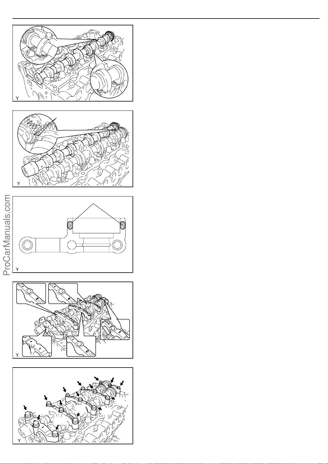
(a) Place the camshaft carrier on the cylinder head.
1CD−FTV ENGINE REPAIR MANUAL (RM1046E)
Page 50
A09625
−ENGINE MECHANICAL PARTIAL ENGINE ASSY (1CD−FTV)(From September,
2003)
14−17
(b) Install the camshaft.
(c) Apply engine oil to the cam and gear of the camshaft, and
the journal of the camshaft carrier.
(d) Place the intake camshaft on the camshaft carrier as
shown in the illustration so that the No. 3 and No. 4 of the
cylinder cam lobes face downward.
Alignment Mark
Seal Packing
43. INSTALL NO.2 CAMSHAFT
(a) Install the No. 2 camshaft.
(b) Apply engine oil to the cam and gear of the camshaft, and
the journal of the camshaft carrier.
(c) Engage the exhaust camshaft gear and intake camshaft
gear by matching the alignment marks on each gear.
(d) Roll down the exhaust camshaft onto the bearing journals
while engaging gears with each other.
A09626
(e) Install the camshaft bearing caps.
(1) Remove any old packing (FIPG) material from the
No. 5 camshaft bearing cap.
(2) Apply seal packing to the No. 5 camshaft bearing
cap as shown in the illustration.
Seal packing: Part No. 08826−00080 or equivalent
A09601
(3) Place the 5 bearing caps in their proper locations.
A09627
11
5
2
8
14
13
1CD−FTV ENGINE REPAIR MANUAL (RM1046E)
7
15
4
1
9
10
12
6
3
A09650
(4) Using several steps, install and tighten the 15 bear-
ing cap bolts uniformly in the sequence shown in the
illustration.
Torque: 20 N×m (204 kgf×cm, 15 ft×lbf)
Page 51
14−18
−ENGINE MECHANICAL PARTIAL ENGINE ASSY (1CD−FTV)(From September,
2003)
Upward
Upward
Notch
Cam Lobe
Clearance
Cam Lobe
Intake
Manifold
Side
A09687
A87966
A88503
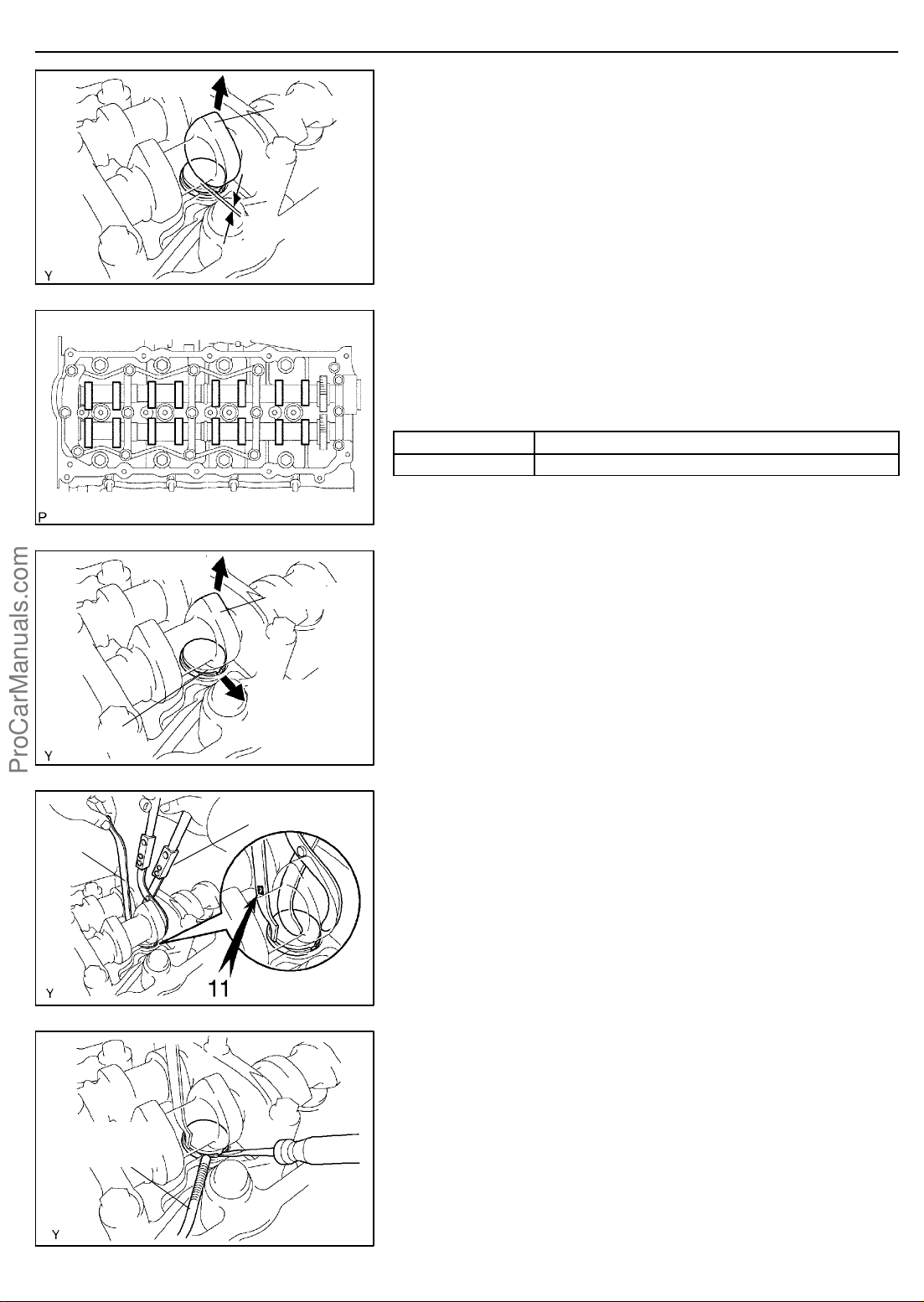
44. INSPECT VALVE CLEARANCE
(a) Turn the crankshaft so that the cam lobe located over the
inspecting valve faces upward.
(b) Using a feeler gauge, measure the clearance between
the valve lifter and camshaft.
(c) Measure the clearance at 16 places.
(d) Record the out−of−specification valve clearance mea-
surements. They will be used later to select an adjusting
shim to replace.
Valve clearance (Cold) :
Intake
Exhaust 0.35 to 0.45 mm (0.014 to 0.018 in.)
0.20 to 0.30 mm (0.008 to 0.012 in.)
45. ADJUST VALVE CLEARANCE
(a) Remove the adjusting shim.
(1) Turn the crankshaft so that the cam lobe located
over the adjusting valve faces upward.
(2) Position the notch of the valve lifter toward the in-
take manifold side.
SST (A)
SST (B)
A62959
Magnetic
Finger
A09615
1CD−FTV ENGINE REPAIR MANUAL (RM1046E)
(3) Using SST (A), press down the valve lifter, then
place SST (B) between the camshaft and valve lift-
er. Remove SST (A).
SST 09248−55050 (09248−05510, 09248−05520)
HINT:
Use SST (B) marked with ”11”.
(4) Remove the adjusting shim using a small screwdriv-
er and magnetic finger.
Page 52
−ENGINE MECHANICAL PARTIAL ENGINE ASSY (1CD−FTV)(From September,
2003)
(b) Select the size of an adjusting shim to replace by following
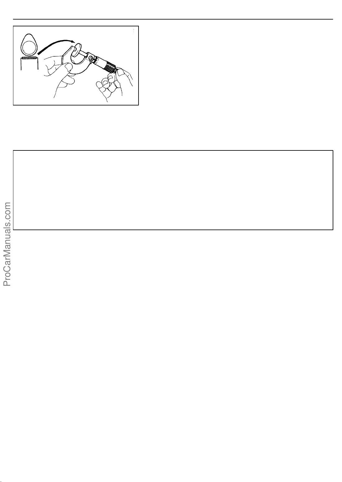
the formula or the charts:
(1) Using a micrometer, measure the thickness of the
removed shim.
(2) Calculate the thickness of a new shim so that the
valve clearance comes within the specified value.
HINT:
T ........... Thickness of the removed adjusting shim
A54826
A ........... Measured valve clearance
N ........... Thickness of a new adjusting shim
Intake: N = T + (A − 0.25 mm (0.010 in.))
Exhaust: N = T + (A − 0.40 mm (0.016 in.))
(3) Select a new shim with a thickness which is as close
to the calculated value as possible.
EXAMPLE (Intake):
Measured valve clearance = 0.45 mm (0.0177 in.)
0.45 mm (0.0177 in.) − 0.25 mm (0.0098 in.) = 0.20 mm (0.0078 in.)
(Measured − Specification = Excess clearance)
Used shim measurement = 2.80 mm (0.1102 in.)
0.20 mm (0.0078 in.) + 2.80 mm (0.1102 in.) = 3.00 mm (0.1181 in.)
(Excess clearance + Used shim = Ideal new shim)
Closest new shim = 3.00 mm (0.1181 in.)
Select No. 21 shim
14−19
HINT:
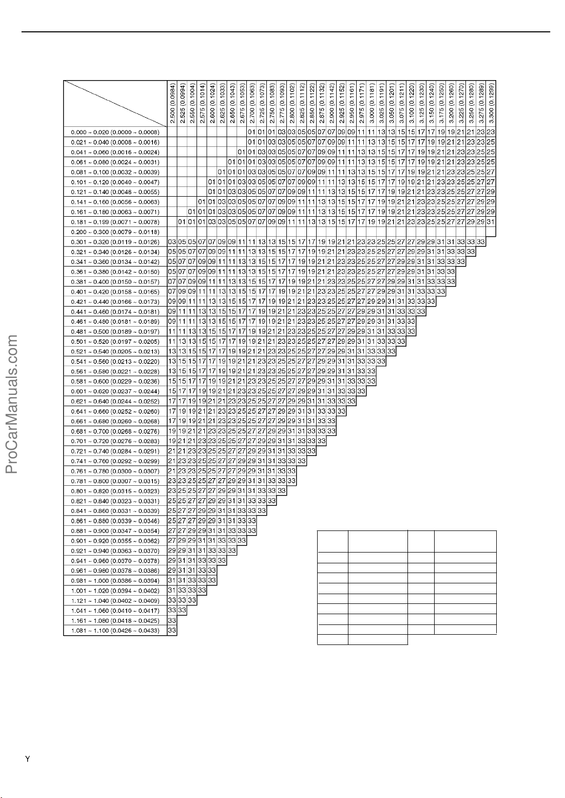
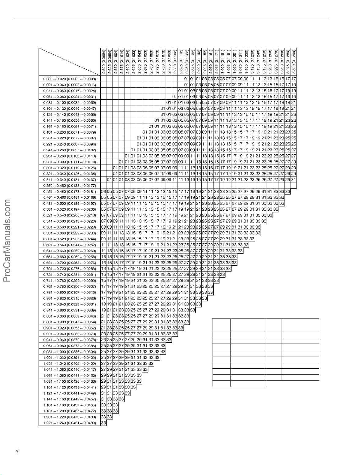
S The shims are available in 17 sizes in increments of 0.05
mm (0.0020 in.), from 2.50 mm (0.0984 in.) to 3.30 mm
(0.1299 in.).
S Refer to New Shim Thickness table on the next 2 pages.
1CD−FTV ENGINE REPAIR MANUAL (RM1046E)
Page 53
14−20
−ENGINE MECHANICAL PARTIAL ENGINE ASSY (1CD−FTV)(From September,
2003)
Adjusting Shim Selection Chart (Intake)
New Shim Thickness mm (in.)
Shim
No.
01
03
05
07
09
11
13
15
17
Thickness
2.500(0.0984)
2.550 (0.1004)
2.600 (0.1024)
2.650 (0.1043)
2.700 (0.1063)
2.750 (0.1083)
2.800 (0.1102)
2.850 (0.1122)
2.900 (0.1142)
Shim
No.
19
21
23
25
27
29
31
33
Thickness
2.950(0.1161)
3.000(0.1181)
3.050(0.1201)
3.100(0.1220)
3.150 (0.1240)
3.200(0.1260)
3.250 (0.1280)
3.300 (0.1299)
Intake valve clearance (Cold):
0.20 to 0.30 mm (0.008 to 0.012 in.)
EXAMPLE: The 2.800 mm (0.1102 in.) shim is installed,
and the measured clearance is 0.450 mm (0.0177 in.).
Replace the 2.800 mm (0.1102 in.) shim with a new No. 21
shim.
A57526
1CD−FTV ENGINE REPAIR MANUAL (RM1046E)
Page 54
−ENGINE MECHANICAL PARTIAL ENGINE ASSY (1CD−FTV)(From September,
2003)
Adjusting Shim Selection Chart (Exhaust)
14−21
New Shim Thickness mm (in.)
Shim
No.
01
03
05
07
09
11
13
15
17
Thickness
2.500(0.0984)
2.550 (0.1004)
2.600 (0.1024)
2.650 (0.1043)
2.700 (0.1063)
2.750 (0.1083)
2.800 (0.1102)
2.850 (0.1122)
2.900 (0.1142)
Shim
No.
19
21
23
25
27
29
31
33
Thickness
2.950(0.1161)
3.000(0.1181)
3.050(0.1201)
3.100(0.1220)
3.150 (0.1240)
3.200(0.1260)
3.250 (0.1280)
3.300 (0.1299)
Exhaust valve clearance (Cold):
0.35 to 0.45 mm (0.014 to 0.018 in.)
EXAMPLE: The 2.800 mm (0.1102 in.) shim is installed,
and the measured clearance is 0.590 mm (0.0232 in.).
Replace the 2.800 mm (0.1102 in.) shim with a new No. 21
shim.
A57527
1CD−FTV ENGINE REPAIR MANUAL (RM1046E)
Page 55
14−22
SST (B)
SST (A)
A09686
−ENGINE MECHANICAL PARTIAL ENGINE ASSY (1CD−FTV)(From September,
2003)
(c) Install the new adjusting shim.
(1) Place the new adjusting shim on the valve lifter.
(2) Using SST (A), press down the valve lifter and re-
move SST (B).
SST 09248−55050 (09248−05510, 09248−05520)
(d) Recheck the valve clearance.
46. INSTALL WATER PUMP ASSY
(a) Install a new gasket and water pump with the 7 bolts.
Torque: 31 N×m (320 kgf×cm, 23 ft×lbf)
Seal Width
2to4mm
(0.08 to 0.16 in.)
Seal Packing
A87943
A09600
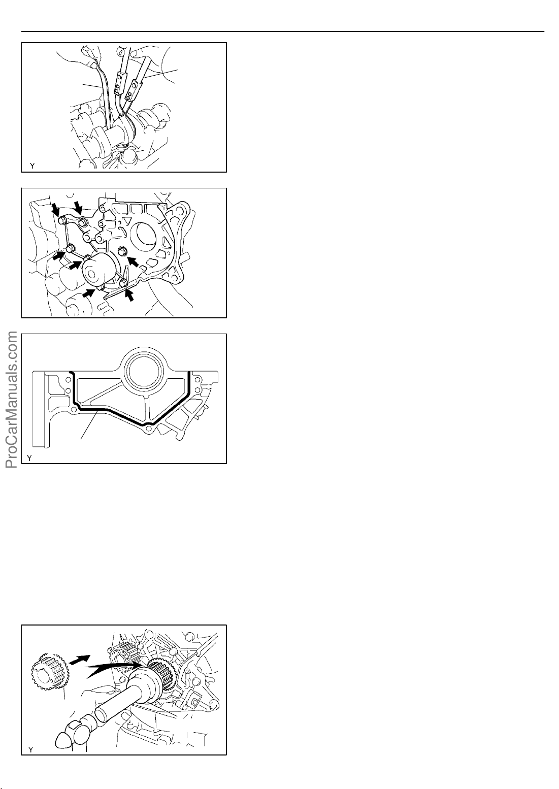
47. INSTALL CAMSHAFT OIL SEAL RETAINER
(a) Apply seal packing to the oil seal retainer as shown in the
illustration.
Seal packing: Part No. 08826−00080 or equivalent
NOTICE:
S Install a nozzle of which opening is cut to 2 to 4 mm
(0.08 to 0.16 in.).
S The parts must be set within 3 minutes and must be
assembled within 15 minutes after applying seal
packing. Otherwise the material must be removed
and reapplied.
S Immediately remove the nozzle from the tube, then re-
install the cap.
(b) Install the oil seal retainer with 4 bolts. Uniformly tighten
the 4 bolts in several passes.
Torque: 9.8 N×m (100 kgf×cm, 7.2 ft×lbf)
Inward
Angle Sensor
SST
A57101
1CD−FTV ENGINE REPAIR MANUAL (RM1046E)
48. INSTALL CRANKSHAFT TIMING PULLEY
(a) Align the keyway of the timing pulley with the key located
on the crankshaft, then slide the pulley into place.
(b) Using SST and a hammer, tap in the timing pulley with the
angle sensor facing inward.
SST 09223−46011
Page 56
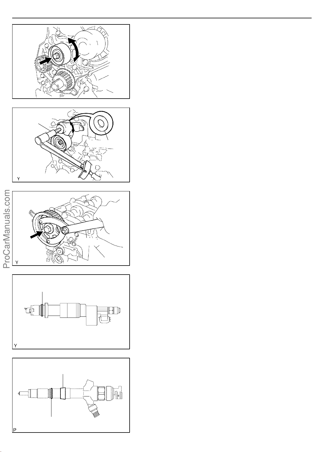
Turn
A57102
−ENGINE MECHANICAL PARTIAL ENGINE ASSY (1CD−FTV)(From September,
2003)
49. INSTALL TIMING BELT IDLER SUB−ASSY NO.2
(a) Install the idler pulley with the bolt.
Torque: 47 N×m (475 kgf×cm, 34 ft×lbf)
(b) Check that the idler pulley moves smoothly.
14−23
8mm
Hexagon
Wrench
SST
New O−ring
Plate Washer
A57103
A62592
A85942
50. INSTALL TIMING BELT IDLER SUB−ASSY NO.1
(a) Using an 8 mm hexagon wrench, install the plate washer
and idler pulley with the idler pulley shaft.
Torque: 35 N×m (357 kgf×cm, 26 ft×lbf)
(b) Check that the pulley bracket moves smoothly.
51. INSTALL CAMSHAFT TIMING PULLEY
(a) Install the pulley set key to the key groove of the cam-
shaft.
(b) Align the keyway of the timing pulley with the key located
on the camshaft, then slide the pulley into place.
(c) Using SST, install the pulley bolt.
SST 09960−10010 (09962−01000, 09963−01000)
Torque: 88 N×m (899 kgf×cm, 65 ft×lbf)
52. INSTALL EXHAUST FUEL ADDITION INJECTOR
ASSY
(a) Install a new gasket to the cylinder head.
(b) Install a new O−ring to the injector.
(c) Apply a light coat of engine oil to the O−ring on the injec-
tor.
(d) Install the addition injector and nozzle holder clamp.
(e) Using a Torx wrench (T40), install the Torx screw.
Torque: 12 N×m (117 kgf×cm, 8.5 ft×lbf)
Back−up ring
O−ring
A79187
1CD−FTV ENGINE REPAIR MANUAL (RM1046E)
53. INSTALL INJECTOR ASSY
(a) Install the 4 new nozzle seats to the cylinder head.
(b) Install new back−up rings and the O−rings to each injec-
tor.
(c) Apply a light coat of engine oil to the O−rings on each in-
jector.
(d) Install the injector to the cylinder head.
NOTICE:
Fit the injectors to the nozzle seats.
Page 57
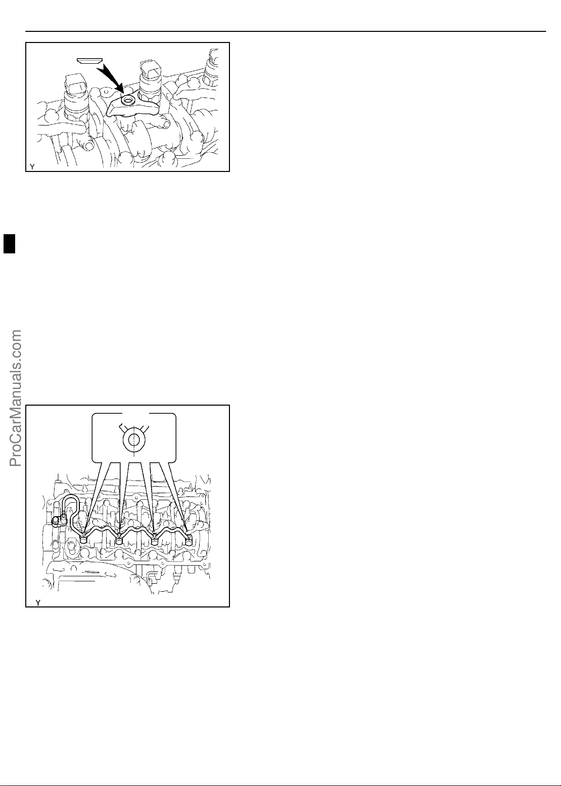
14−24
A93841
−ENGINE MECHANICAL PARTIAL ENGINE ASSY (1CD−FTV)(From September,
2003)
(e) Install the nozzle holder clamp as shown in the illustration.
Tighten the camshaft bearing cap bolt by hand to fix the
nozzle holder clamp.
NOTICE:
S Pay attention to the mounting orientation of the wash-
er.
S When temporarily attaching the nozzle holder clamp
and mounting bolt, be careful not to orient them at an
angle.
HINT:
Apply a light coat of engine oil to the threads of the nozzle holder clamp bolts.
(f) Install the injection pipe No. 1, No. 2, No. 3 and No. 4, then
tighten the nuts by hand.
(g) Install new 5 gaskets and the leakage pipe No. 1. Tighten
the 4 hollow screws by hand.
(h) Tighten the 4 nozzle holder clamp bolts.
Torque: 26 N×m (265 kgf×cm, 19 ft×lbf)
(i) Remove the 4 injection pipes.
54. INSTALL NOZZLE LEAKAGE PIPE ASSY
(a) Remove the bolt which is tightened at the center of the
camshaft bearing cap No. 4.
90_
A85760
(b) Install the nozzle leakage pipe and 4 new gaskets.
NOTICE:
When installing the gaskets, pay attention to the mounting
orientation. Install the gasket so that the joint of the gasket
comes within the ranges shown in the illustration.
(c) Apply a light coat of engine oil to the 4 hollow screws and
bolt.
(d) Tighten the 4 hollow screws and bolt by hand.
(e) Tighten the 4 hollow screws and bolt.
Torque:
16 N×m (163 kgf×cm, 12 ft×lbf) for hollow screw
20 N×m (204 kgf×cm, 15 ft×lbf) for flange bolt
NOTICE:
In any case, when the torque exceeds the upper limit, replace the leakage pipe hollow screw and gaskets with new
ones.
(f) Check that there are no leaks from the nozzle leakage
pipe connection.
(1) Apply a light coat of soapy water (any fluid to detect
fuel leakage) to the nozzle leakage pipe connection.
1CD−FTV ENGINE REPAIR MANUAL (RM1046E)
Page 58
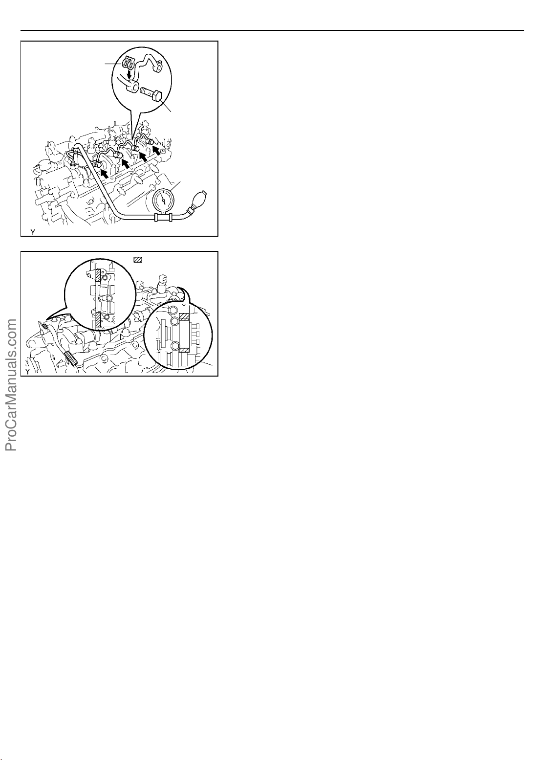
New Gasket
Hollow
Screw
SST
A86430
−ENGINE MECHANICAL PARTIAL ENGINE ASSY (1CD−FTV)(From September,
2003)
14−25
(2) Using SST (a turbocharger pressure gauge), attach
SST to the fuel return side of the nozzle leakage
pipe, then maintain 100 kPa (1.0 kgf/cm2, 14.5 psi)
of pressure for 60 seconds to check that there are
no bubbles from the pipe connection.
SST 09992−00242
(3) After checking fuel leaks, wipe off soapy water from
the pipe connection.
: Seal Packing
A09663
55. INSTALL CYLINDER HEAD COVER SUB−ASSY
(a) Remove any old packing (FIPG) material.
(b) Apply seal packing to the cylinder head.
Seal packing: Part No. 08826−00080 or equivalent
(c) Install the gasket to the head cover.
(d) Install the cylinder head cover with 10 bolts.
Torque: 13 N×m (135 kgf×cm, 9.7 ft×lbf)
1CD−FTV ENGINE REPAIR MANUAL (RM1046E)
Page 59
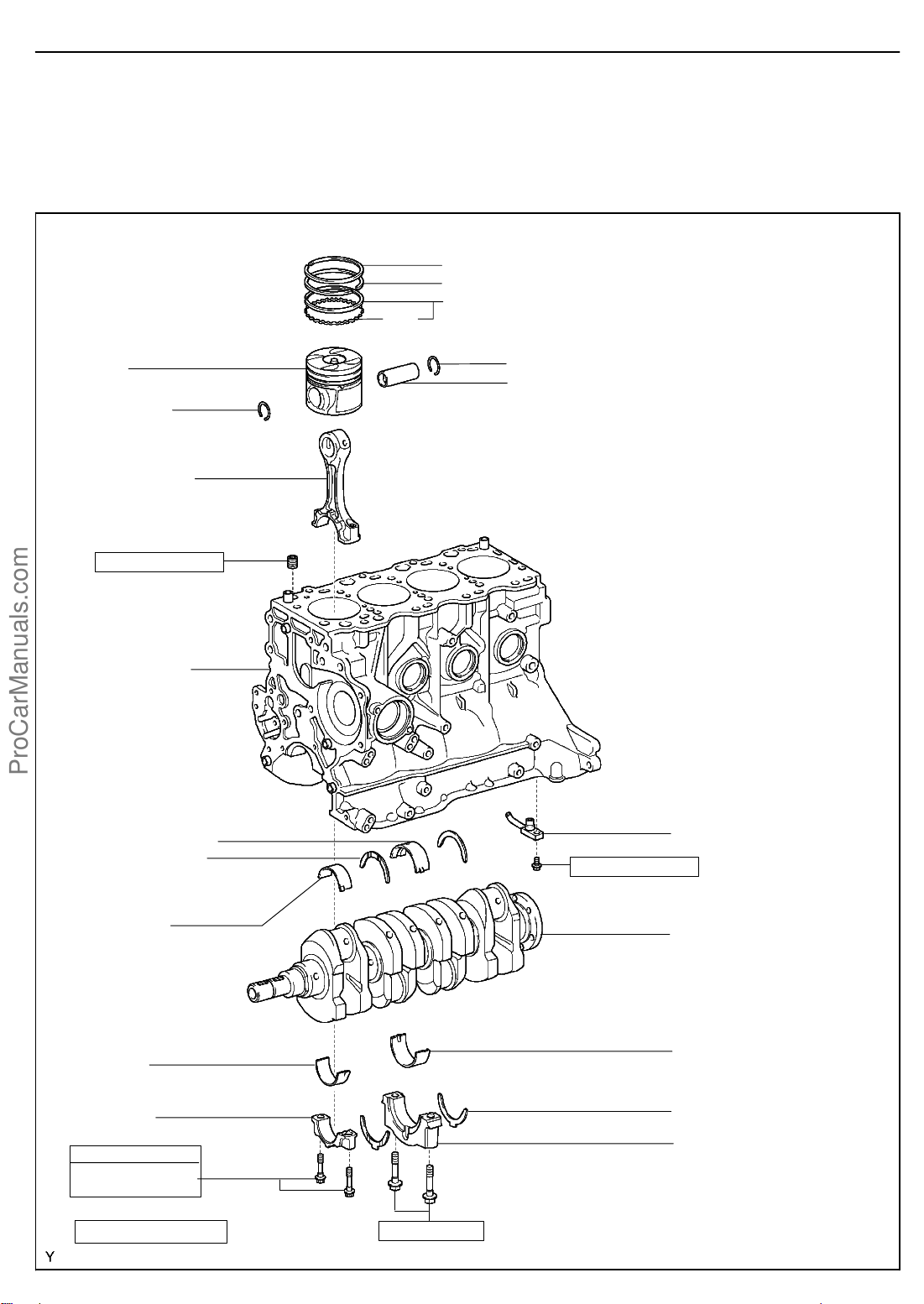
14−42
−ENGINE MECHANICAL CYLINDER BLOCK ASSY (1CD−FTV)(From September,
2003)
CYLINDER BLOCK ASSY (1CD−FTV)(From September,
2003)
COMPONENTS
No. 1 Piston Ring
No. 2 Piston Ring
Oil Ring
Coil
141NT−01
Piston
z Snap Ring
Connecting Rod
9.0 (92, 78 in.·lbf)
Cylinder Block
Oil Orifice
Cylinder Block
Upper Main Bearing
Upper Crankshaft
Thrust Washer
z Snap Ring
Piston Pin
Sub−assy
Oil Nozzle No. 1
7.4 (76, 67 in.·lbf)
Connecting Rod
Bearing
Connecting Rod
Bearing
Connecting
Rod Cap
See Page 14−43
1st 30 (306, 22)
2nd Turn 90˚
N·m (kgf·cm, ft·lbf)
: Specified torque
z Non−reusable part
1CD−FTV ENGINE REPAIR MANUAL (RM1046E)
Crankshaft
Lower Main Bearing
Lower Crankshaft
Thrust Washer
Main Bearing Cap
115 (1,173, 85)
A62605
Page 60
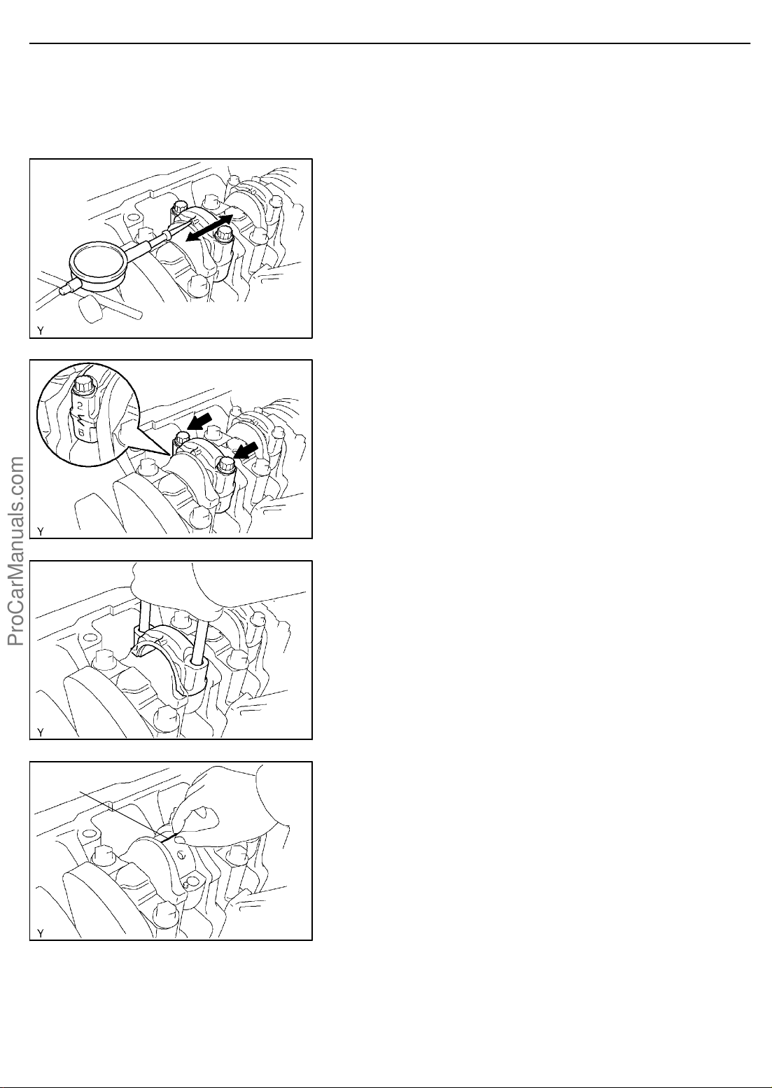
OVERHAUL
A09477
−ENGINE MECHANICAL CYLINDER BLOCK ASSY (1CD−FTV)(From September,
2003)
14−43
141NU−01
1. INSPECT CONNECTING ROD THRUST CLEARANCE
(a) Using a dial indicator, measure the thrust clearance while
moving the connecting rod back and forth.
Standard thrust clearance:
0.08 to 0.40 mm (0.0031 to 0.0157 in.)
If the thrust clearance is greater than maximum, replace the
connecting rod assembly(s). If necessary, replace the crankshaft.
2. INSPECT CONNECTING ROD OIL CLEARANCE
(a) Check the match marks on the connecting rod and cap to
ensure correct reassembly.
(b) Remove the 2 connecting rod cap bolts.
Plastigage
A09488
(c) Using the 2 removed connecting rod cap bolts, remove
the connecting rod cap and lower bearing by wiggling the
connecting rod cap right and left.
HINT:
Keep the lower bearing attached to the connecting rod cap.
A09492
(d) Clean the crank pin and bearing.
(e) Check the crank pin and bearing for pits and scratches.
If the crank pin or bearing is damaged, replace the bearings. If
necessary, replace the crankshaft.
(f) Lay a strip of Plastigage across the crank pin.
A09494
1CD−FTV ENGINE REPAIR MANUAL (RM1046E)
Page 61
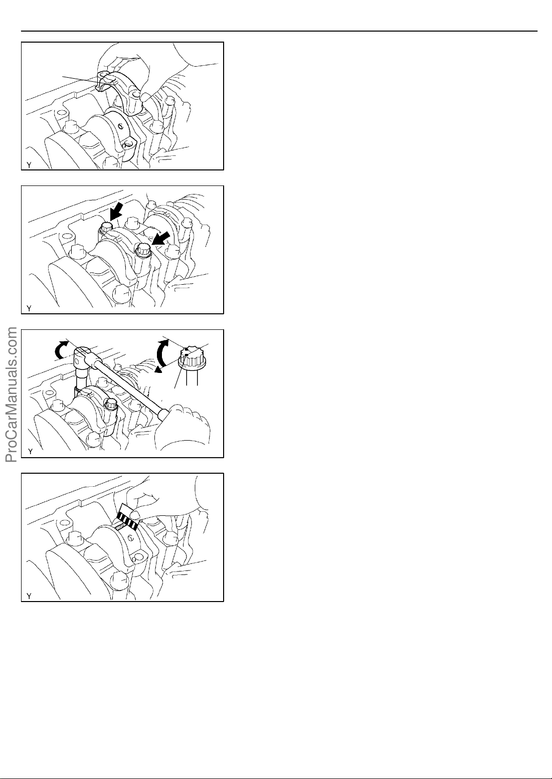
14−44
Front Mark
(Protrusion)
A09514
−ENGINE MECHANICAL CYLINDER BLOCK ASSY (1CD−FTV)(From September,
2003)
(g) Match the numbered connecting rod cap with the con-
necting rod.
(h) Install the connecting rod cap with the front mark facing
forward.
(i) Apply a light coat of engine oil to the threads and under-
heads of the connecting rod cap bolts.
(j) Install and alternately tighten the 2 cap bolts in several
steps.
Torque: 30 N×m (306 kgf×cm, 22 ft×lbf)
If any of the cap bolts does not meet the specified torque, replace the connecting rod cap bolts.
90_
90_
Front
A09493
Painted Mark
A09490
A09495
(k) Mark the front of the cap bolt with paint.
(l) Retighten the cap bolts by 90_ as illustrated.
(m) Check that the painted mark is now at a 90_ angle to the
front.
NOTICE:
Do not turn the crankshaft.
(n) Remove the 2 bolts, connecting rod cap and lower bear-
ing.
(o) Measure the Plastigage at its widest point.
Standard oil clearance:
0.038 to 0.056 mm (0.0015 to 0.0022 in.)
Maximum oil clearance: 0.10 mm (0.0039 in.)
If the oil clearance is greater than maximum, replace the bearings. If necessary, replace the crankshaft.
1CD−FTV ENGINE REPAIR MANUAL (RM1046E)
Page 62
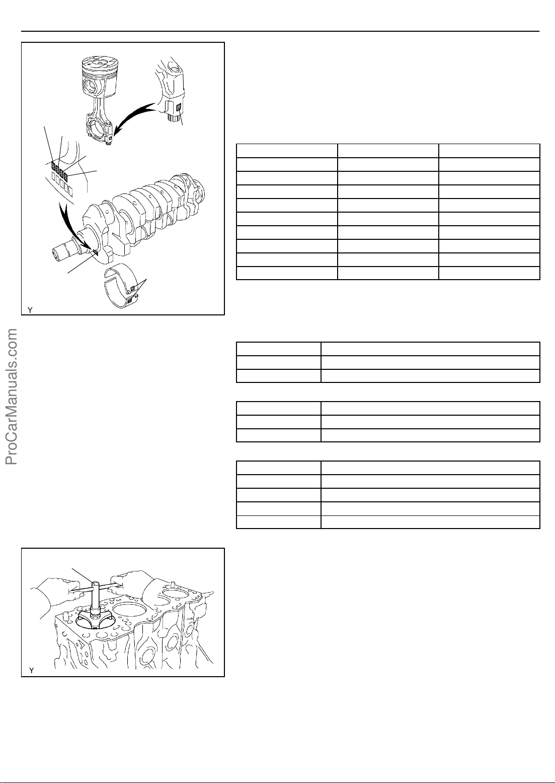
No. 1
No. 2
No. 3
No. 4
Mark
0,1 or 2
Ridge Reamer
Mark
1, 2 or 3
Mark
1, 2, 3, 4 or 5
A09472
A56037
−ENGINE MECHANICAL CYLINDER BLOCK ASSY (1CD−FTV)(From September,
2003)
14−45
(p) If using the standard bearing, replace it with one having
the same number. If the number of the bearing cannot be
determined, find the correct number of the bearing by adding together the numbers imprinted on the crankshaft
and connecting rod cap, then select the bearing with the
same number as the total. There are 5 sizes of standard
bearings, marked ”1”, ”2”, ”3”, ”4” and ”5” accordingly.
Connecting Rod Cap
1 0 1
1 1 2
1 2 3
2 0 2
2 1 3
2 2 4
3 0 3
3 1 4
3 2 5
Crankshaft Use Bearing
HINT:
EXAMPLE: Connecting rod cap ”2” + Crankshaft ”1”
= Total number 3 (Use bearing ”3”)
Connecting rod big end inside diameter:
Mark ”1”
Mark ”2” 53.506 to 53.512 mm (2.1065 to 2.1068 in.)
Mark ”3” 53.512 to 53.518 mm (2.1068 to 2.1070 in.)
53.500 to 53.506 mm (2.1063 to 2.1065 in.)
Crankshaft crank pin diameter:
Mark ”0”
Mark ”1” 50.488 to 50.494 mm (1.9877 to 1.9880 in.)
Mark ”2” 50.482 to 50.488 mm (1.9875 to 1.9877 in.)
50.494 to 50.500 mm (1.9880 to 1.9882 in.)
Standard size bearing center wall thickness:
Mark ”1” 1.478 to 1.481 mm (0.0582 to 0.0583 in.)
Mark ”2” 1.481 to 1.484 mm (0.0583 to 0.0584 in.)
Mark ”3” 1.484 to 1.487 mm (0.0584 to 0.0585 in.)
Mark ”4” 1.487 to 1.490 mm (0.0585 to 0.0587 in.)
Mark ”5” 1.490 to 1.493 mm (0.0587 to 0.0588 in.)
(q) Completely remove the Plastigage.
3. REMOVE PISTON SUB−ASSY W/CONNECTING ROD
(a) Using a ridge reamer, remove all the carbon from the top
of the cylinder.
(b) Push the piston, connecting rod assembly and upper
bearing through the top of the cylinder block.
HINT:
S Keep the bearing, connecting rod and cap together.
S Arrange the piston and connecting rod assemblies in the
correct order.
4. REMOVE CONNECTING ROD BEARING
1CD−FTV ENGINE REPAIR MANUAL (RM1046E)
Page 63
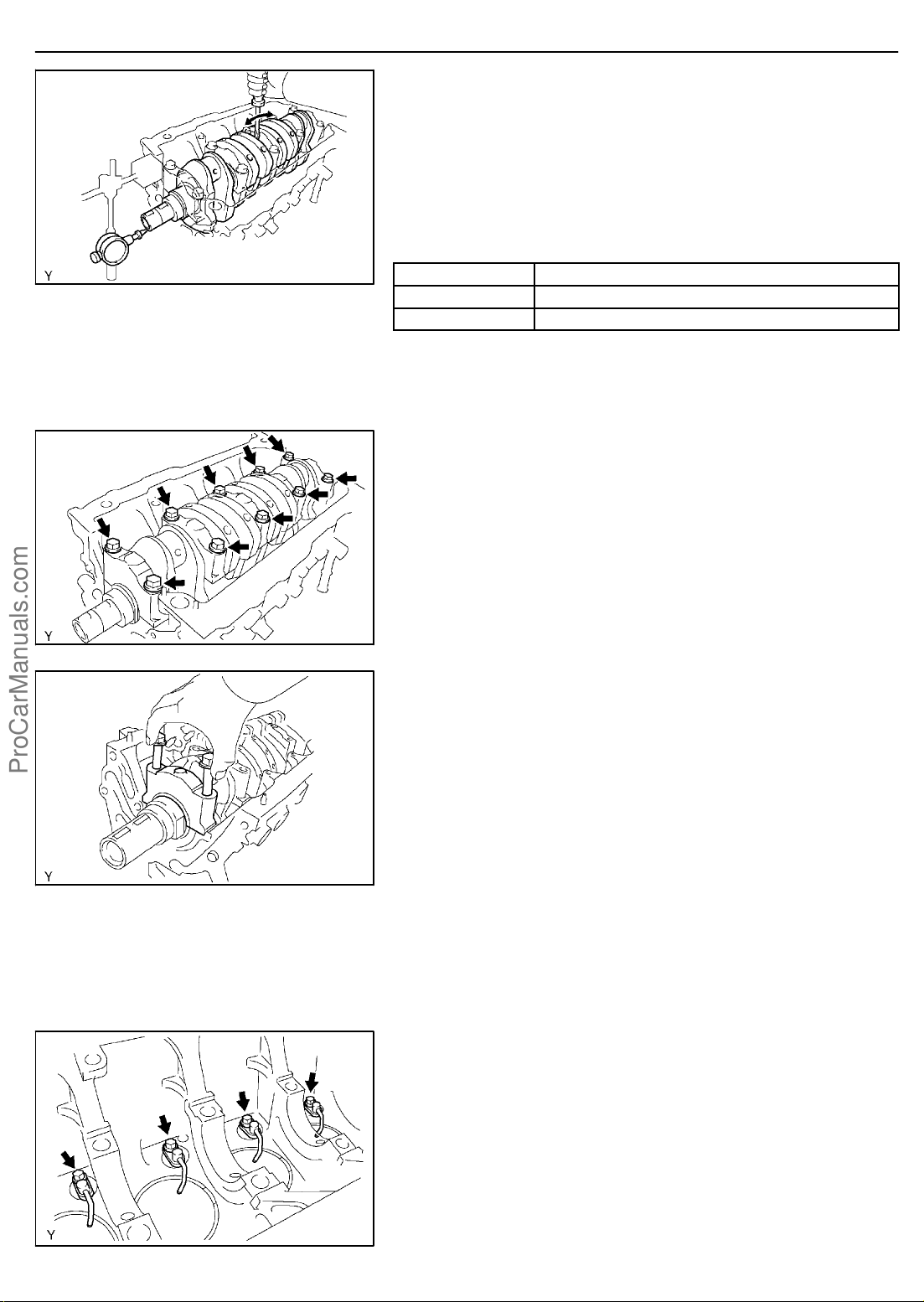
14−46
A09496
−ENGINE MECHANICAL CYLINDER BLOCK ASSY (1CD−FTV)(From September,
2003)
5. INSPECT CRANKSHAFT THRUST CLEARANCE
(a) Using a dial indicator, measure the thrust clearance while
prying the crankshaft back and forth with a screwdriver.
Standard thrust clearance:
0.040 to 0.300 mm (0.0016 to 0.0118 in.)
If the thrust clearance is greater than maximum, replace the
thrust washer as a set.
Thrust washer thickness:
Standard
Oversize 0.125 2.743 to 2.793 mm (0.1080 to 0.1100 in.)
Oversize 0.250 2.805 to 2.855 mm (0.1104 to 0.1124 in.)
2.680 to 2.730 mm (0.1055 to 0.1075 in.)
6. REMOVE CRANKSHAFT
(a) Uniformly loosen and remove the 10 main bearing cap
bolts.
A09497
A08026
(b) Using the removed main bearing cap bolts, wiggle the cap
back and forth, then remove the 5 main bearing caps, 5
lower bearings and 2 lower thrust washers (the No. 3 main
bearing cap only).
HINT:
S Keep the lower bearing and main bearing cap together.
S Arrange the main bearing caps and lower thrust washers
in the correct order.
(c) Lift the crankshaft out.
HINT:
Keep the upper bearing and upper thrust washers together with
the cylinder block.
7. REMOVE SUB−ASSY OIL NOZZLE NO.1
(a) Remove the 4 bolts and 4 oil nozzles.
A85943
1CD−FTV ENGINE REPAIR MANUAL (RM1046E)
Page 64
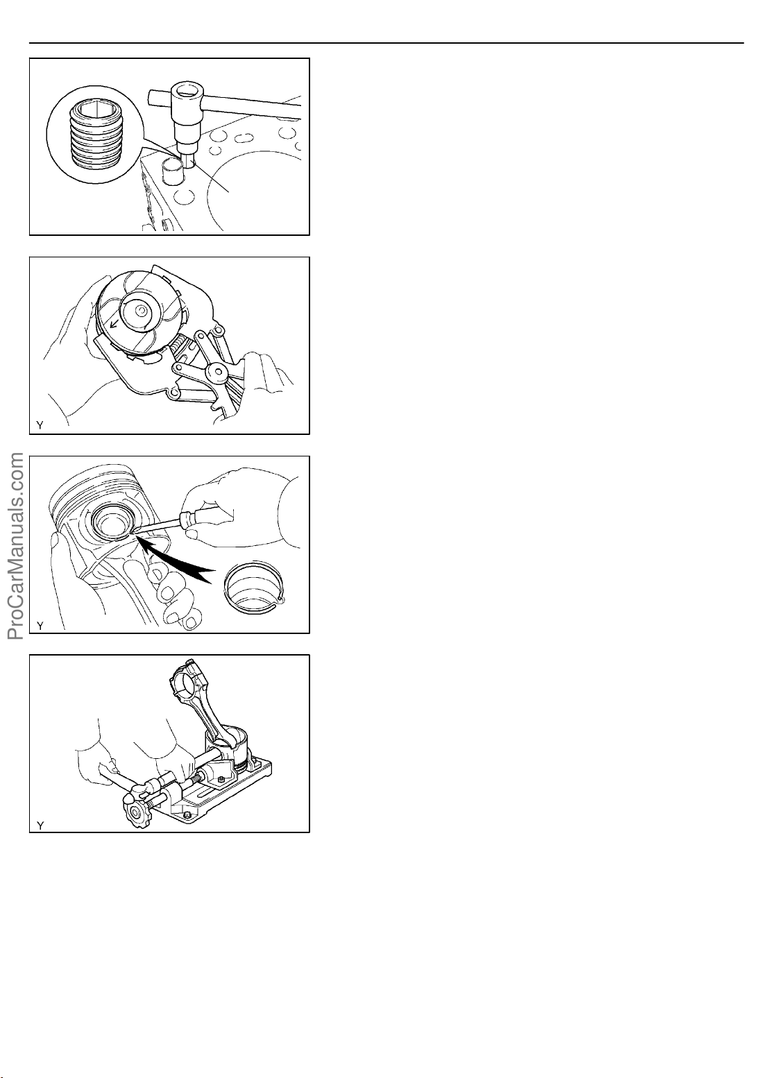
6mm
Hexagon
Wrench
A87939
A87944
−ENGINE MECHANICAL CYLINDER BLOCK ASSY (1CD−FTV)(From September,
2003)
14−47
8. REMOVE CYLINDER BLOCK OIL ORIFICE
(a) Using a hexagon wrench (6 mm), remove the oil orifice.
9. REMOVE PISTON RING SET
(a) Using a piston ring expander, remove the No. 1 and No.
2 piston ring and oil ring.
NOTICE:
Try to keep the piston ring expansion as small as possible.
(b) Remove the coil by hand.
HINT:
Arrange the piston rings in the correct order.
10. REMOVE W/PIN PISTON SUB−ASSY
(a) Using a small screwdriver, pry the snap rings off the pis-
ton.
(b) Gradually heat the piston up to approximately 60_C
(140_F).
A09502
(c) Using a plastic−faced hammer and brass bar, lightly tap
out the piston pin and remove the connecting rod.
HINT:
S The piston and pin are a matched set.
S Arrange the pistons, pins, rings, connecting rods and
bearings in the correct order.
A09501
1CD−FTV ENGINE REPAIR MANUAL (RM1046E)
Page 65
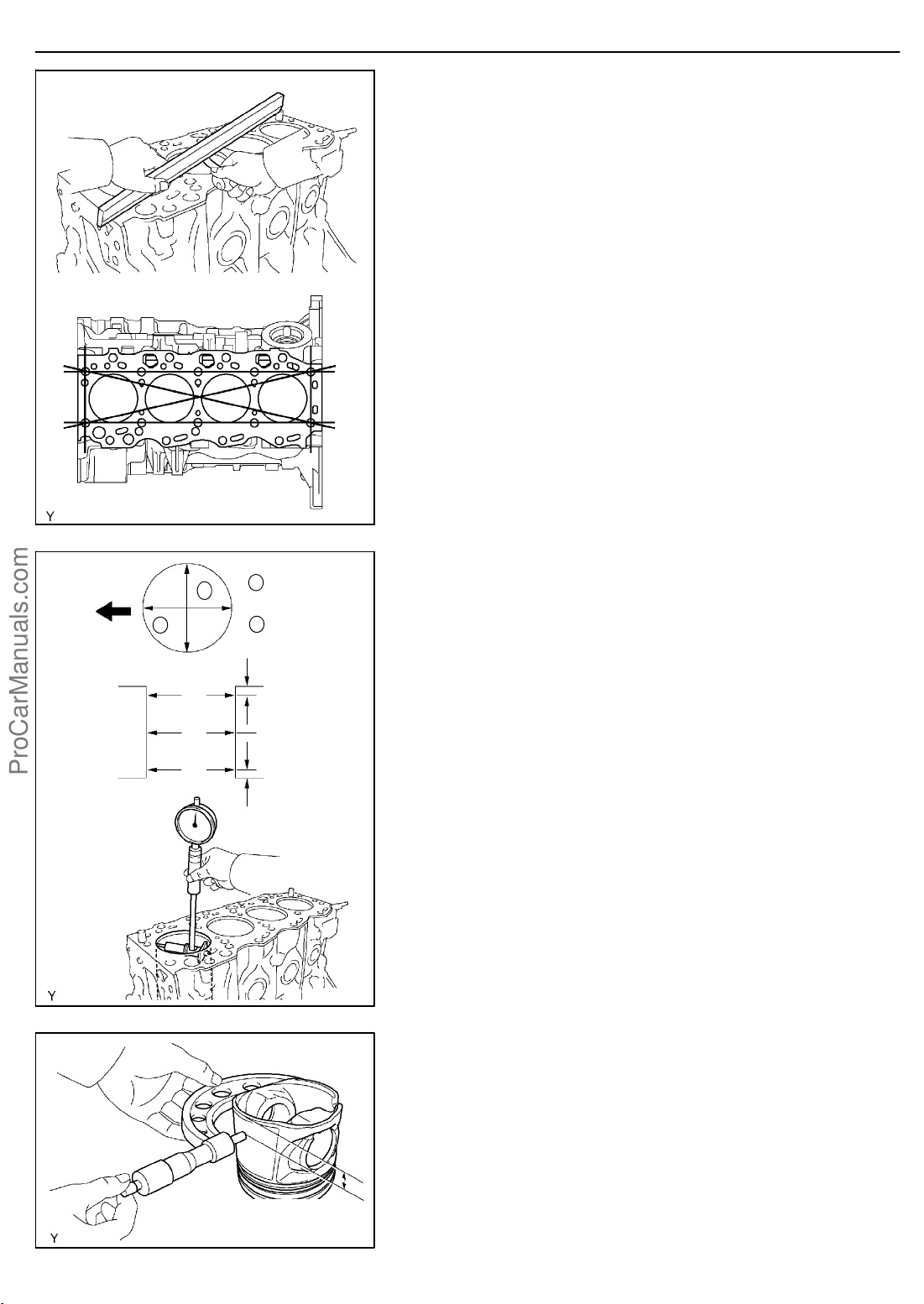
14−48
−ENGINE MECHANICAL CYLINDER BLOCK ASSY (1CD−FTV)(From September,
2003)
11. INSPECT CYLINDER BLOCK FOR FLATNESS
(a) Using a precision straight edge and feeler gauge, mea-
sure the warpage on the surface which contacts the cylinder head gasket.
Maximum warpage: 0.05 mm (0.0020 in.)
If the warpage is greater than maximum, replace the cylinder
block.
1
Front
2
A
B
C
Thrust
1
Direction
2
Axial
Direction
10mm
(0.39 in)
10mm
(0.39 in)
A09453
12. INSPECT CYLINDER BORE DIAMETER
(a) Using a cylinder gauge, measure the cylinder bore diame-
ter at positions A, B and C in the thrust and axial directions.
Standard diameter:
82.200 to 82.400 mm (3.2362 to 3.2441 in.)
If the diameter is greater than maximum, replace the cylinder
block.
A09455
14 mm
(0.55 in.)
1CD−FTV ENGINE REPAIR MANUAL (RM1046E)
A88537
13. INSPECT W/PIN PISTON SUB−ASSY
(a) Using a micrometer, measure the piston diameter at a
right angle to the piston pin center line and 14 mm (0.55
in.) from the skirt bottom edge.
Piston diameter:
82.118 to 82.132 mm (3.2330 to 3.2335 in.)
Page 66
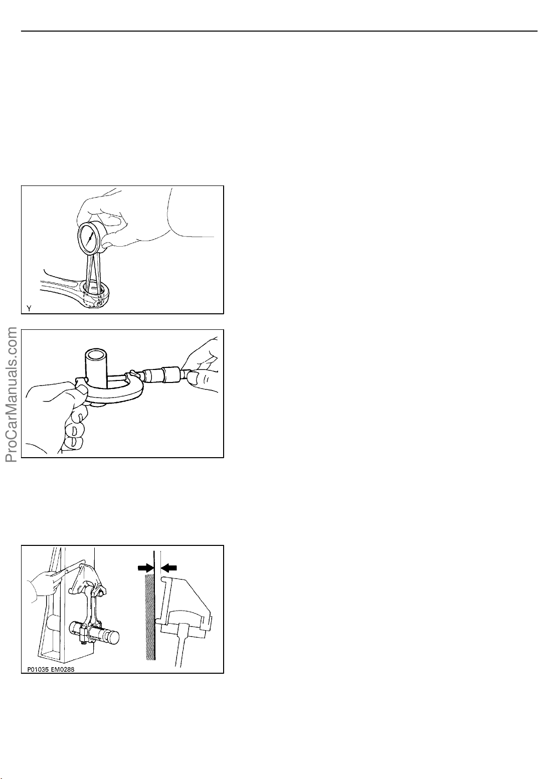
−ENGINE MECHANICAL CYLINDER BLOCK ASSY (1CD−FTV)(From September,
2003)
14−49
(b) Subtract the piston diameter measurement from the cylin-
der bore diameter measurement.
Standard oil clearance:
0.068 to 0.140 mm (0.0027 to 0.0055 in.)
If the oil clearance is greater than maximum, replace all the 4
pistons. If necessary, replace the cylinder block.
(c) Using a caliper gauge, measure the inside diameter of the
connecting rod bushing.
Bushing inside diameter:
31.015 to 31.027 mm (1.2211 to 1.2215 in.)
A09693
EM0227
(d) Using a micrometer, measure the piston pin diameter.
Piston pin diameter:
31.000 to 31.012 mm (1.2205 to 1.2209 in.)
(e) Subtract the piston pin diameter measurement from the
bushing inside diameter measurement.
Standard oil clearance:
0.005 to 0.019 mm (0.0002 to 0.0007 in.)
If the oil clearance is greater than maximum, replace the connecting rod. If necessary, replace the piston and piston pin as
a set.
14. INSPECT CONNECTING ROD SUB−ASSY
(a) Using a rod aligner and feeler gauge, check the connect-
ing rod alignment.
(1) Inspect the misalignment.
Maximum misalignment:
0.05 mm (0.0020 in.) per 100 mm (3.94 in.)
If the alignment is greater than maximum, replace the connecting rod assembly.
Z00064
1CD−FTV ENGINE REPAIR MANUAL (RM1046E)
Page 67
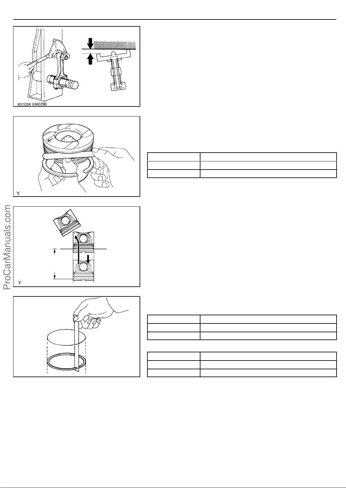
14−50
Z00065
A87945
−ENGINE MECHANICAL CYLINDER BLOCK ASSY (1CD−FTV)(From September,
2003)
(2) Inspect the twist.
Maximum twist:
0.15 mm (0.0059 in.) per 100 mm (3.94 in.)
If the twist is greater than maximum, replace the connecting rod
assembly.
15. INSPECT RING GROOVE CLEARANCE
(a) Using a feeler gauge, measure the clearance between a
new piston ring and wall of the ring groove.
Ring groove clearance:
No. 1
No. 2 0.075 to 0.115 mm (0.0030 to 0.0045 in.)
Oil 0.03 to 0.07 mm (0.0012 to 0.0028 in.)
0.11 to 0.15 mm (0.0043 to 0.0059 in.)
If the clearance is not as specified, replace the piston.
110 mm
(4.33 in.)
A88538
EM7639
16. INSPECT PISTON RING END GAP
(a) Using a piston, push the piston ring until it is a little below
the bottom of the ring travel, 110 mm (4.33 in.) from the
top of the cylinder block.
(b) Using a feeler gauge, measure the end gap.
Standard end gap:
No. 1
No. 2 0.39 to 0.54 mm (0.0154 to 0.0213 in.)
Oil 0.20 to 0.40 mm (0.0079 to 0.0157 in.)
0.27 to 0.39 mm (0.0106 to 0.0514 in.)
Maximum end gap:
No. 1 0.82 mm (0.0323 in.)
No. 2 1.00 mm (0.0394 in.)
Oil 0.90 mm (0.0354 in.)
If the end gap is greater than maximum, replace the piston ring.
If the end gap is greater than maximum, even with a new piston
ring, replace the cylinder block.
1CD−FTV ENGINE REPAIR MANUAL (RM1046E)
Page 68
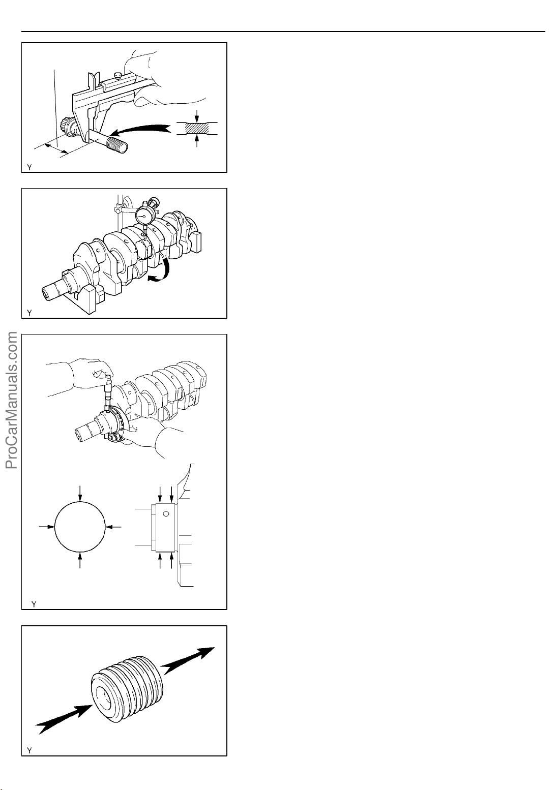
20 mm (0.79 in.)
A09491
−ENGINE MECHANICAL CYLINDER BLOCK ASSY (1CD−FTV)(From September,
2003)
14−51
17. INSPECT CONNECTING ROD BOLT
(a) Using vernier calipers, measure the tension portion diam-
eter.
Standard diameter:
8.0 to 8.3 mm (0.315 to 0.327 in.)
If the diameter is less than minimum, replace the connecting rod
bolt.
18. INSPECT CRANKSHAFT
(a) Place the crankshaft on V−blocks.
(b) Using a dial indicator, measure the circle runout at the
center journal.
Maximum circle runout: 0.025 mm (0.0010 in.)
If the circle runout is greater than maximum, replace the crankshaft.
A56040
(c) Using a micrometer, measure the diameter of each main
journal and crank pin.
Main journal diameter:
56.992 to 57.010 mm (2.2438 to 2.2445 in.)
Crank pin diameter:
50.482 to 50.500 mm (1.9875 to 1.9882 in.)
If the diameter is not as specified, replace the crankshaft.
(d) Check each main journal and crank pin for taper and out−
of−round as illustrated.
Maximum taper and out−of−round:
0.01 mm (0.0004 in.)
If the taper and out−of−round is greater than maximum, replace
the crankshaft.
A56041
A09474
1CD−FTV ENGINE REPAIR MANUAL (RM1046E)
19. INSPECT CYLINDER BLOCK OIL ORIFICE
(a) Check the oil orifice for clogging.
If necessary, replace the oil orifice.
20. INSPECT CRANKSHAFT OIL CLEARANCE
(a) Clean each main journal and bearing.
Page 69
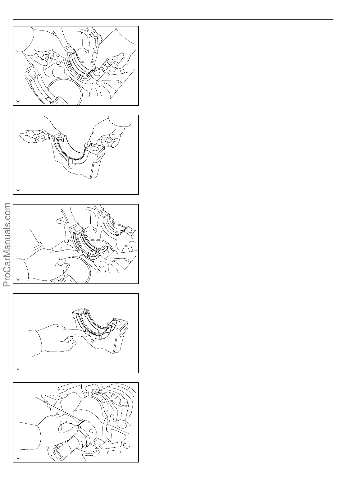
14−52
A56038
−ENGINE MECHANICAL CYLINDER BLOCK ASSY (1CD−FTV)(From September,
2003)
(b) Install the bearing on the cylinder block and bearing cap.
HINT:
Each upper bearing has an oil groove and oil hole and each lower bearing does not.
(1) Align the bearing claw with the claw groove of the
cylinder clock, then push in the 5 upper bearings.
(2) Align the bearing claw with the claw groove of the
main bearing cap, then push in the 5 lower bear-
ings.
Groove
Groove
A56042
(c) Install the 2 thrust washers under the No. 3 journal posi-
tion of the cylinder block with the oil grooves facing outward.
A56039
(d) Install the 2 thrust washers on the No. 3 bearing cap with
the oil grooves facing outward.
(e) Place the crankshaft on the cylinder block.
A09512
Plastigage
A09499
1CD−FTV ENGINE REPAIR MANUAL (RM1046E)
(f) Lay a strip of Plastigage across each journal.
Page 70
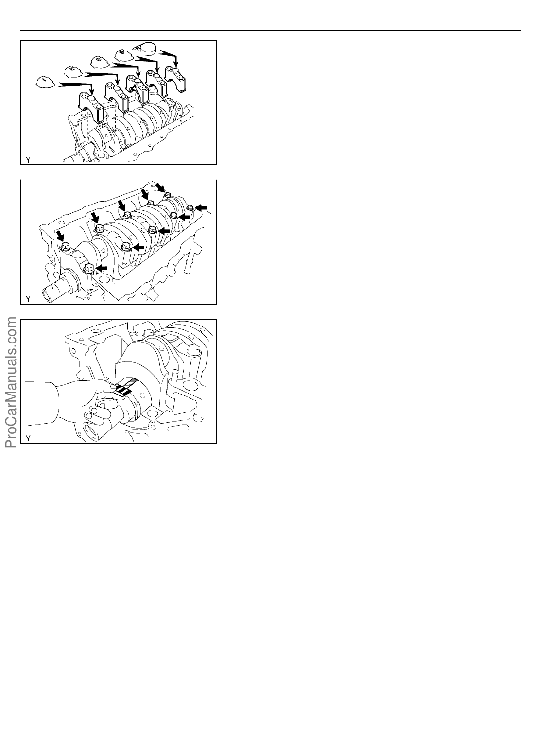
A56043
A09497
−ENGINE MECHANICAL CYLINDER BLOCK ASSY (1CD−FTV)(From September,
2003)
14−53
(g) Install the 5 main bearing caps in their proper locations.
HINT:
Each bearing cap has a number and front mark.
(h) Apply a light coat of engine oil to the threads and under
the heads of the main bearing cap bolts.
(i) Install and uniformly tighten the 10 bolts of the main bear-
ing cap in several steps.
Torque: 115 N×m (1,173 kgf×cm, 85 ft×lbf)
NOTICE:
Do not turn the crankshaft.
(j) Remove the bearing cap.
(k) Measure the Plastigage at its widest point.
Standard oil clearance:
0.032 to 0.100 mm (0.0013 to 0.0039 in.)
If the oil clearance is greater than maximum, replace the bearing. If necessary, replace the crankshaft.
A09500
1CD−FTV ENGINE REPAIR MANUAL (RM1046E)
Page 71
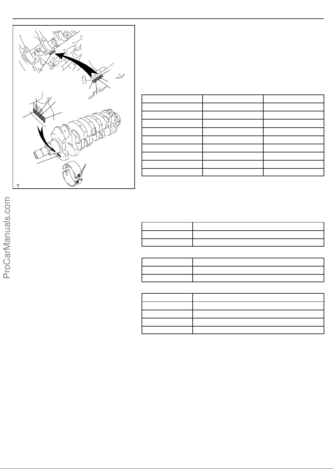
14−54
Mark
1, 2 or 3
No. 2
No. 3
No. 1
No. 4
No. 5
No. 1
Mark
0, 1 or 2
No. 5
No. 4
No. 3
No. 2
Mark
1, 2, 3, 4 or 5
A09688
−ENGINE MECHANICAL CYLINDER BLOCK ASSY (1CD−FTV)(From September,
2003)
(l) If using the standard bearing, replace it with one having
the same number. If the number of the bearing cannot be
determined, find the correct number of the bearing by adding together the numbers imprinted on the cylinder block
and crankshaft, then select the bearing with the same
number as the total. There are 5 sizes of standard bearings, marked ”1”, ”2”, ”3”, ”4” and ”5” accordingly.
Number Marked
Cylinder Block
1 0 1
1 1 2
1 2 3
2 0 2
2 1 3
2 2 4
3 0 3
3 1 4
3 2 5
Crankshaft Use Bearing
HINT:
EXAMPLE
Cylinder block ”2” + Crankshaft ”1” = Total number 3 (Use bearing ”3”)
Cylinder block main journal bore diameter:
Mark ”1”
Mark ”2” 61.006 to 61.012 mm (2.4018 to 2.4020 in.)
Mark ”3” 61.012 to 61.018 mm (2.4020 to 2.4023 in.)
61.000 to 61.006 mm (2.4016 to 2.4018 in.)
Crankshaft main journal diameter:
Mark ”0”
Mark ”1” 56.998 to 57.004 mm (2.2440 to 2.2443 in.)
Mark ”2” 56.992 to 56.998 mm (2.2438 to 2.2440 in.)
57.004 to 57.010 mm (2.2443 to 2.2445 in.)
Standard size bearing center wall thickness:
Mark ”1” 1.976 to 1.979 mm (0.0778 to 0.0779 in.)
Mark ”2” 1.979 to 1.982 mm (0.0779 to 0.0780 in.)
Mark ”3” 1.982 to 1.985 mm (0.0780 to 0.0781 in.)
Mark ”4” 1.985 to 1.988 mm (0.0781 to 0.0783 in.)
Mark ”5” 1.988 to 1.991 mm (0.0783 to 0.0784 in.)
(m) Completely remove the Plastigage.
1CD−FTV ENGINE REPAIR MANUAL (RM1046E)
Page 72
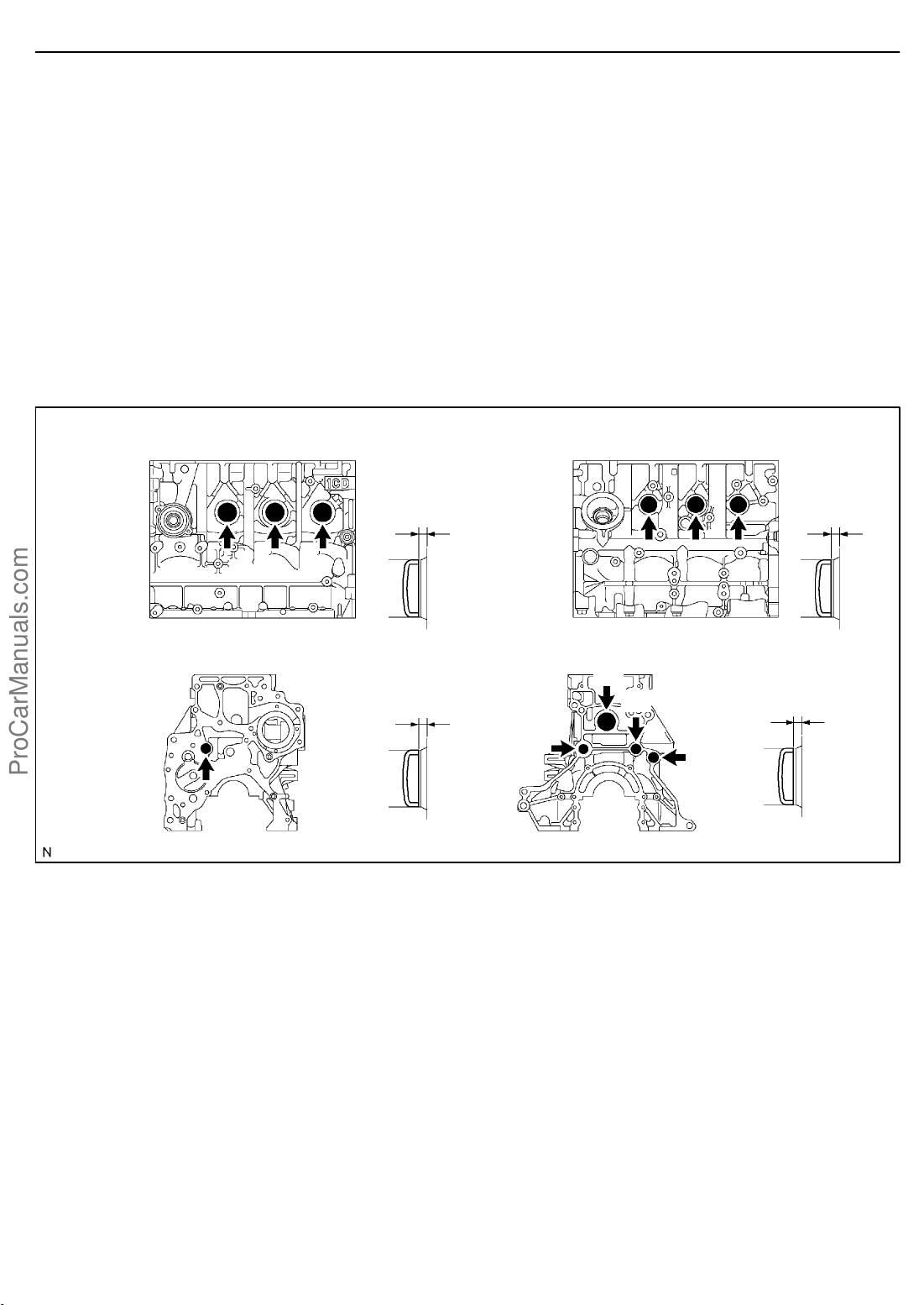
−ENGINE MECHANICAL CYLINDER BLOCK ASSY (1CD−FTV)(From September,
2003)
14−55
21. INSTALL TIGHT PLUG
(a) Apply adhesive around new tight plugs.
Adhesive: Part No.08833 − 00070, THREE BOND 1324
or equivalent.
(b) Using SST, tap in the tight plugs as shown tn the illustra-
tion.
SST 09950−60010 (09951−00350), 09950−70010
(09951−07100)
Standard depth:
2.0 mm (0.079 in.) for intake side
2.0 mm (0.079 in.) for exhaust side
1.5 mm (0.059 in.) for front side
1.5 mm (0.059 in.) for rear side A
2.0 mm (0.079 in.) for rear side B
Intake Side:
Front Side:
2.0 mm
(0.079 in.)
1.5 mm
(0.059 in.)
Exhaust Side:
Rear Side:
B
A
2.0 mm
(0.079 in.)
A 1.5 mm
(0.059 in.)
B 2.0 mm
A
A
(0.079 in.)
A59623
1CD−FTV ENGINE REPAIR MANUAL (RM1046E)
Page 73
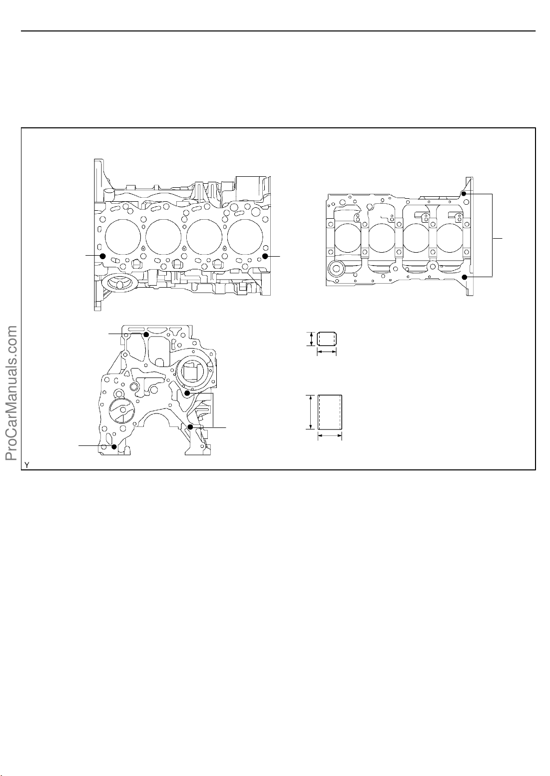
14−56
−ENGINE MECHANICAL CYLINDER BLOCK ASSY (1CD−FTV)(From September,
2003)
22. INSTALL RING PIN
(a) Using a plastic−faced hammer, tap in new ring pins until
their protrusion heights are as specified.
Cylinder Head Side: Lower Side:
A
B
Front Side:
A
A
A
B
8mm
(0.315 in.)
20 mm
(0.787 in.)
Protrusion Height: 5.0 mm (0.197 in.)
11 mm (0.433 in.)
A
Protrusion Height: 13 mm (0.512 in.)
14 mm (0.55 in.)
B
A87940
1CD−FTV ENGINE REPAIR MANUAL (RM1046E)
Page 74
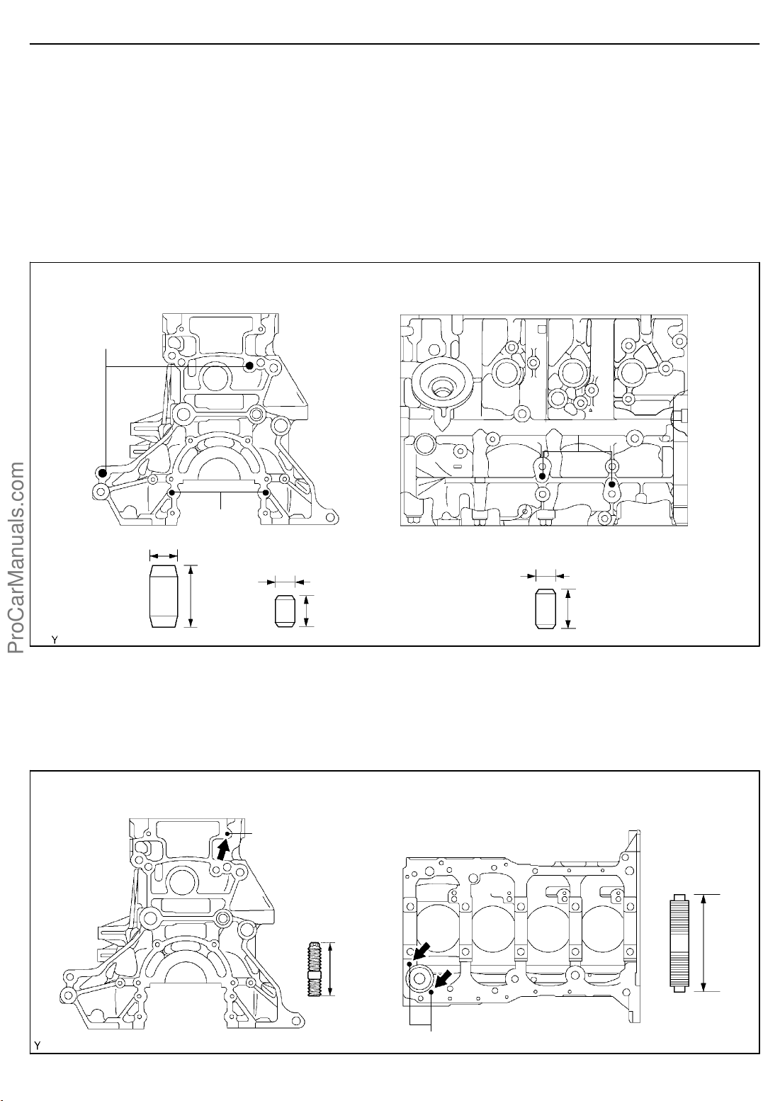
−ENGINE MECHANICAL CYLINDER BLOCK ASSY (1CD−FTV)(From September,
2003)
14−57
23. INSTALL STRAIGHT PIN
(a) Using a plastic−faced hammer, tap in new straight pins.
Standard protrusion:
13 mm (0.5118 in.) for straight pin A
4.0 mm (0.1575 in.) for straight pin B
5.0 mm (0.1968 in.) for straight pin C
Rear Side: Exhaust Side:
A
C
B
10 mm (0.394 in.)
6 mm (0.236 in.)
22 mm
11 mm
(0.433 in.)
A
(0.866 in.)
B
24. INSTALL STUD BOLT
(a) Install the stud bolts as shown in the illustration.
Torque: 2.9 N×m (30 kgf×cm, 27 in.×lbf)
Rear Side: Lower Side:
A
27.5 mm
(1.083 in.)
6 mm (0.236 in.)
14 mm
(0.551 in.)
C
A87941
28 mm
(1.102
in.)
1CD−FTV ENGINE REPAIR MANUAL (RM1046E)
A (M6) B (M6)
B
A87942
Page 75
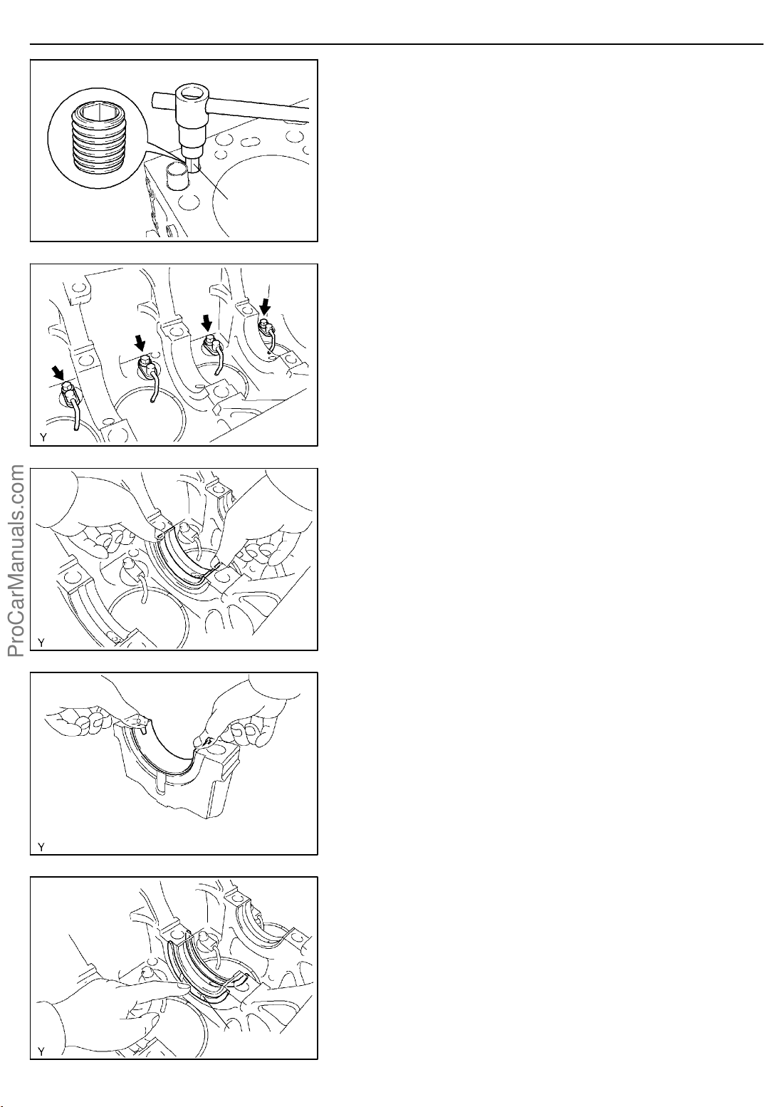
14−58
6mm
Hexagon
Wrench
A87939
−ENGINE MECHANICAL CYLINDER BLOCK ASSY (1CD−FTV)(From September,
2003)
25. INSTALL CYLINDER BLOCK OIL ORIFICE
(a) Using a hexagon wrench (6 mm), install the oil orifice.
Torque: 9.0 N×m (92 kgf×cm, 80 in.×lbf)
26. INSTALL SUB−ASSY OIL NOZZLE NO.1
(a) Install the 4 oil nozzles with the 4 bolts.
Torque: 7.4 N×m (75 kgf×cm, 65 in.×lbf)
A85943
27. INSTALL CRANKSHAFT
(a) Install the bearing on the cylinder block and bearing cap.
HINT:
Each upper bearing has an oil groove and oil hole and each lower bearing does not.
(1) Align the bearing claw with the claw groove of the
cylinder block, then push in the 5 upper bearings.
A56044
(2) Align the bearing claw with the claw groove of the
main bearing cap, then push in the 5 lower bear-
ings.
A56045
Groove
1CD−FTV ENGINE REPAIR MANUAL (RM1046E)
A09510
(b) Install the 2 thrust washers under the No. 3 journal posi-
tion of the cylinder block with the oil grooves facing outward.
Page 76
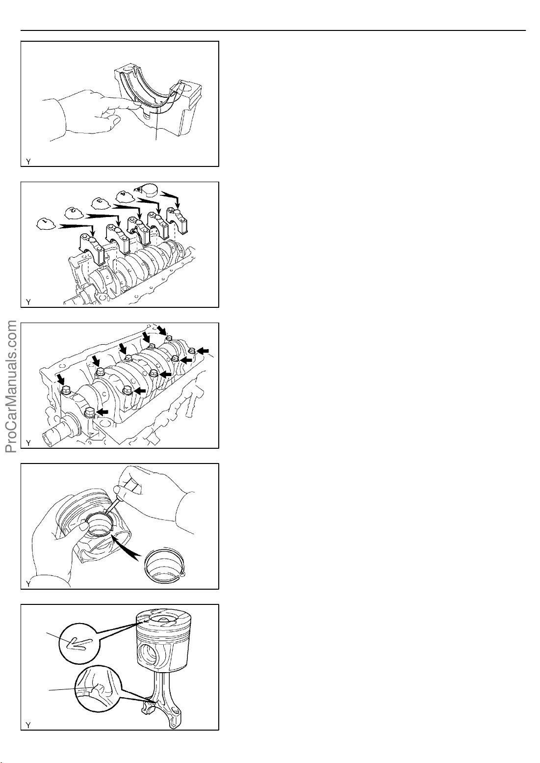
Groove
A09512
−ENGINE MECHANICAL CYLINDER BLOCK ASSY (1CD−FTV)(From September,
2003)
14−59
(c) Install the 2 thrust washers on the No. 3 bearing cap with
the oil grooves facing outward.
(d) Install the 5 main bearing caps in their proper locations.
HINT:
Each bearing cap has a number and font mark.
A56048
(e) Apply a light coat of engine oil to the threads and under-
heads of the main bearing cap bolts.
(f) Install and uniformly tighten the 10 bolts of the main bear-
ing cap in several steps.
Torque: 115 N×m (1,173 kgf×cm, 85 ft×lbf)
(g) Check that the crankshaft turns smoothly.
A09497
28. INSTALL W/PIN PISTON SUB−ASSY
(a) Install a new snap ring on one side of the piston pin hole.
(b) Gradually heat the piston up to approximately 60_C
(140_F).
(c) Coat the piston pin and piston hole of the piston with en-
gine oil.
A56046
Front Mark
(Arrow)
Front Mark
(Protrusion)
A87946
1CD−FTV ENGINE REPAIR MANUAL (RM1046E)
(d) Align the front marks of the piston and connecting rod,
then push in the piston pin by hand.
(e) Install a new snap ring on the other side of the piston pin
hole.
Page 77
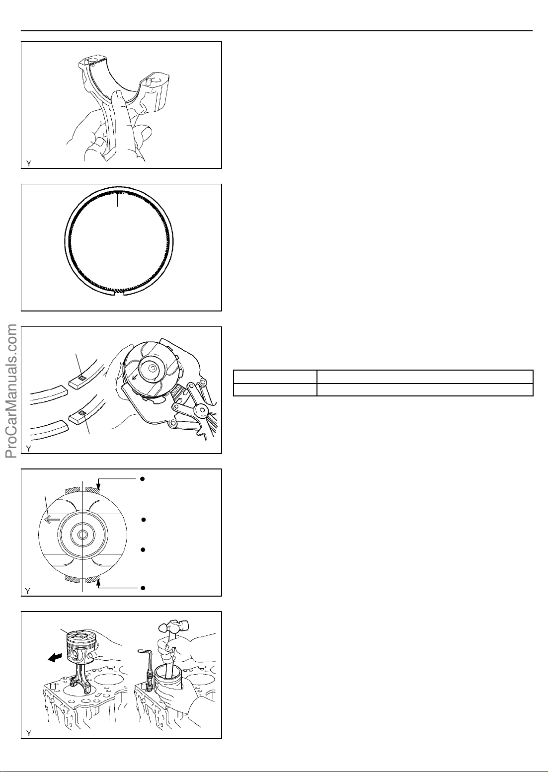
14−60
Coil Joint
A09508
−ENGINE MECHANICAL CYLINDER BLOCK ASSY (1CD−FTV)(From September,
2003)
29. INSTALL CONNECTING ROD BEARING
(a) Align the bearing claw with the groove of the connecting
rod or connecting cap.
(b) Install the bearings in the connecting rod and connecting
rod cap.
30. INSTALL PISTON RING SET
(a) Install the coil by hand.
(b) Using a piston ring expander, install the oil ring.
HINT:
Align the oil ring so its end faces the opposite of the coil joint.
Oil Ring End
Code Mark
No. 1
No. 2
Code Mark
Front Mark
(Arrow)
A56047
A87947
No. 1
Compression
Ring
Oil Ring
No. 2
Compression
Ring
Coil
A87948
(c) Using a piston ring expander, install the No. 2 and No. 1
piston rings with the code mark facing upward.
Code mark:
No. 1
No. 2 2T
1T
NOTICE:
Try to keep the piston ring expansion as small as possible.
(d) Position the piston rings so that the ring ends are as illus-
trated.
31. INSTALL PISTON SUB−ASSY W/CONNECTING ROD
(a) Apply engine oil to the cylinder walls, pistons, and sur-
faces of the connecting rod bearings.
(b) Check the position of the piston ring ends.
Front Mark
(Arrow)
Push
Front
A09511
1CD−FTV ENGINE REPAIR MANUAL (RM1046E)
(c) Using a piston ring compressor, push the correctly−num-
bered piston and connecting rod assemblies into each
cylinder with the front mark of the piston facing forward.
Page 78
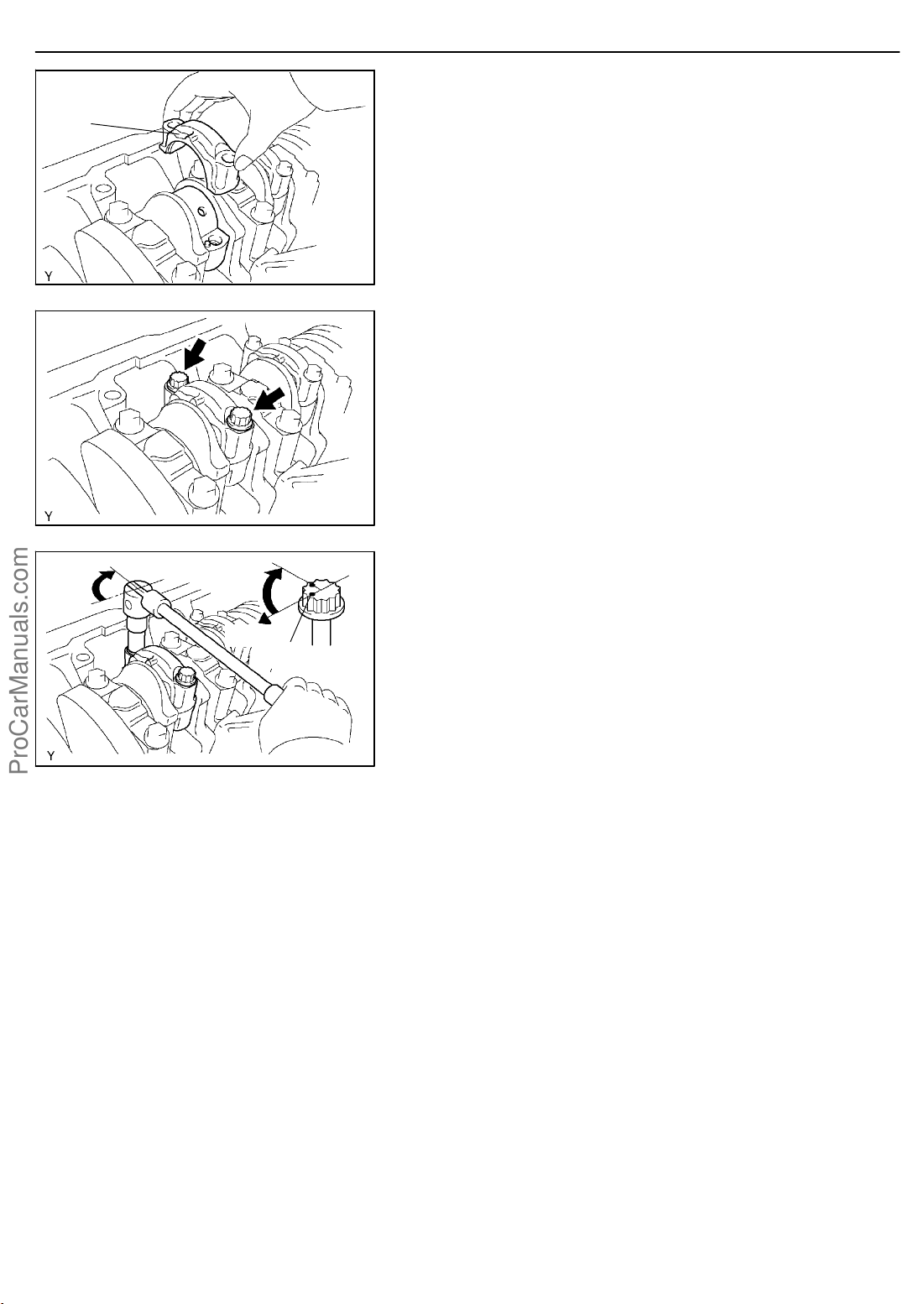
−ENGINE MECHANICAL CYLINDER BLOCK ASSY (1CD−FTV)(From September,
2003)
14−61
Front Mark
(Protrusion)
90_
90_
Front
Painted Mark
(d) Match the numbered connecting rod cap with the con-
necting rod.
(e) Install the connecting rod cap with the front mark facing
forward.
(f) Apply a light coat of engine oil to the threads and under-
heads of the connecting rod cap bolts.
A09514
(g) Install and alternately tighten the 2 cap bolts in several
steps.
Torque: 30 N×m (306 kgf×cm, 22 ft×lbf)
If any of the cap bolts does not meet the specified torque, replace the connecting rod cap bolts.
A09493
(h) Mark the front of the cap bolt with paint.
(i) Retighten the cap bolts by 90_ as illustrated.
(j) Check that the painted mark is now at a 90_ angle to the
front.
(k) Check that the crankshaft turns smoothly.
A09490
1CD−FTV ENGINE REPAIR MANUAL (RM1046E)
Page 79
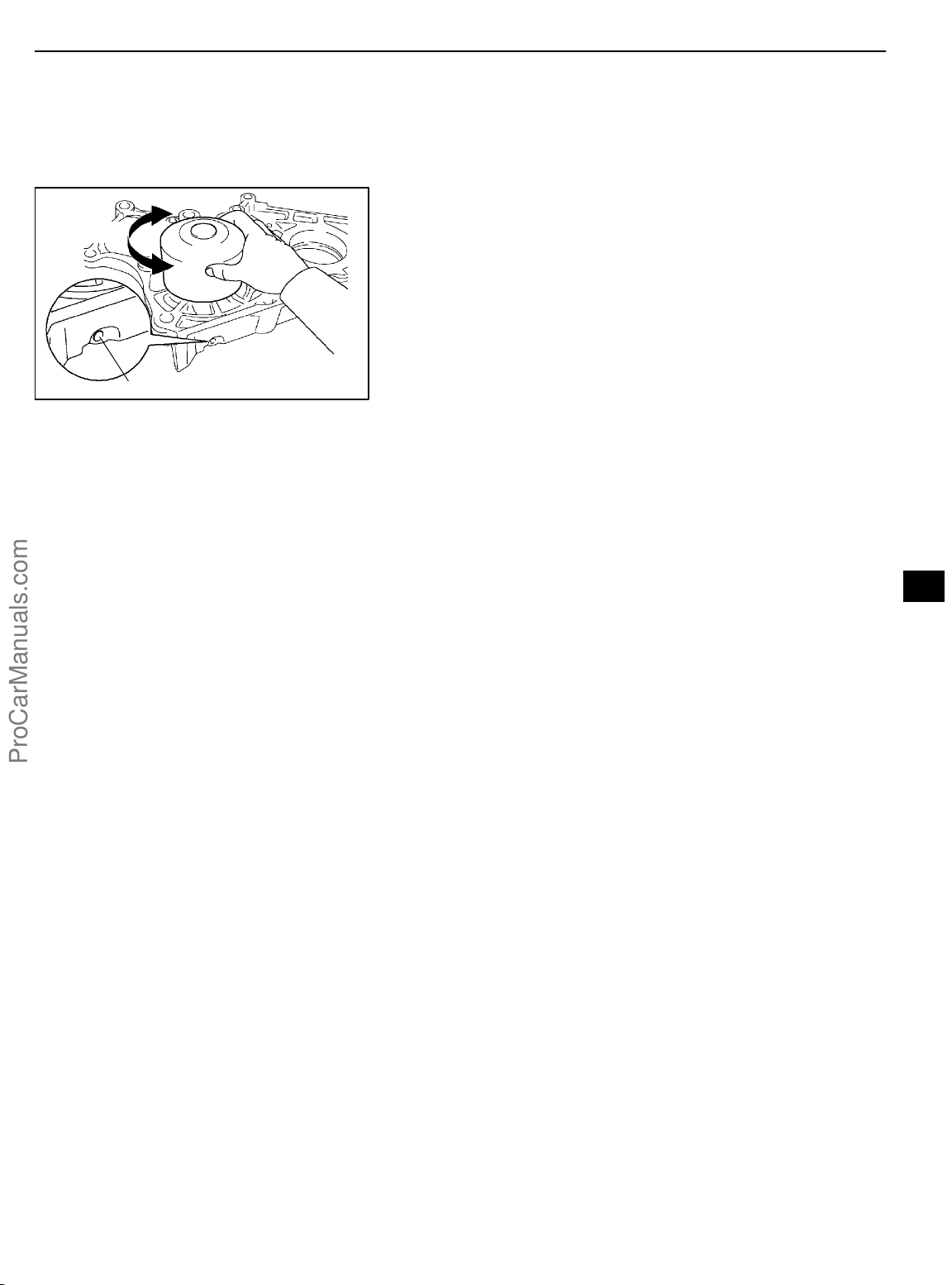
−COOLING WATER PUMP ASSY (1CD−FTV)(From September,
2003)
16−1
WATER PUMP ASSY (1CD−FTV)(From September, 2003)
INSPECTION
1. INSPECT WATER PUMP ASSY
Turn
Drain Hole
A55603
(a) Visually check the drain hole for coolant leakage.
If leakage is found, replace the water pump.
(b) Turn the pulley, then check that the water pump bearing
moves smoothly without making a noise.
If necessary, replace the water pump.
160T5−01
1CD−FTV ENGINE REPAIR MANUAL (RM1046E)
Page 80
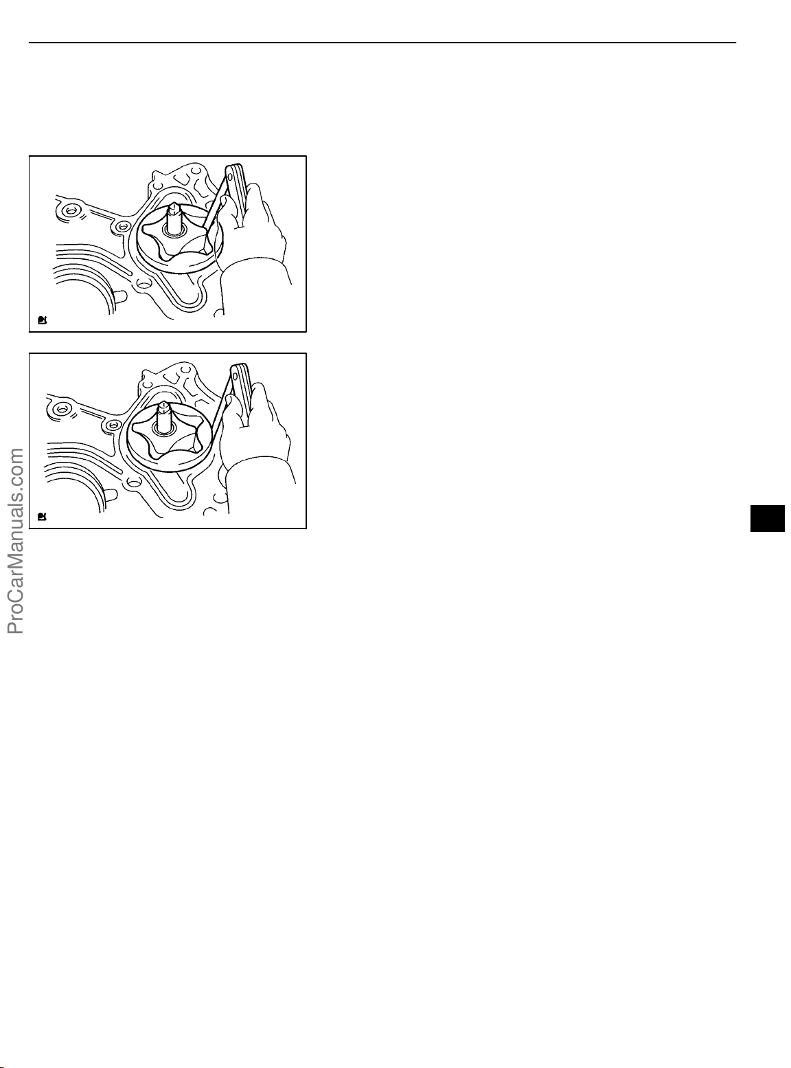
−LUBRICATION OIL PUMP ASSY (1CD−FTV)(From September, 2003)
17−1
OIL PUMP ASSY (1CD−FTV)(From September, 2003)
INSPECTION
1. INSPECT OIL PUMP ASSY
(a) Inspect the tip clearance.
(1) Using a feeler gauge, measure the clearance be-
tween the drive and driven rotor tips.
Standard tip clearance:
0.08 to 0.20 mm (0.0031 to 0.0079 in.)
A55604
(b) Inspect the body clearance.
(1) Using a feeler gauge, measure the clearance be-
tween the driven rotor and body.
Standard body clearance:
0.1 to 0.20 mm (0.0039 to 0.0079 in.)
170J0−01
A55605
1CD−FTV ENGINE REPAIR MANUAL (RM1046E)
Page 81
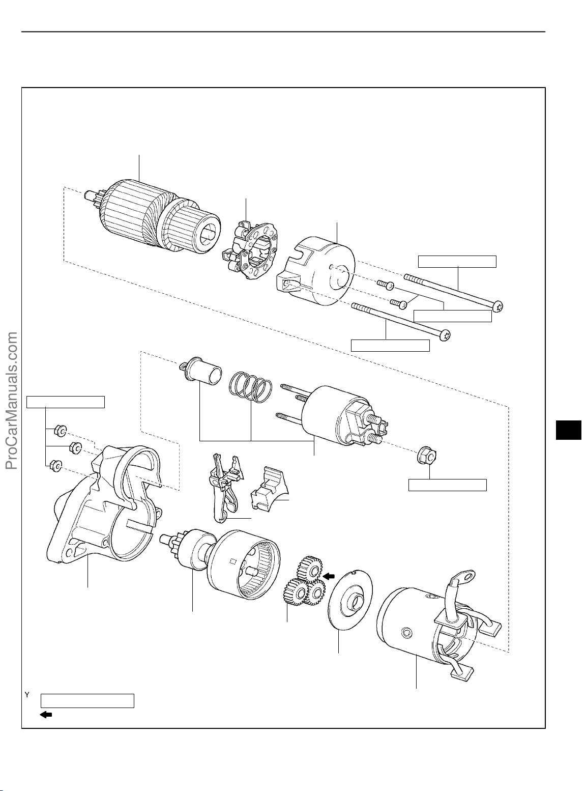
−STARTING & CHARGING STARTER ASSY (1CD−FTV)(From September, 2003)
19−1
STARTER ASSY (1CD−FTV)(From September, 2003)
COMPONENTS
Starter Armature Assy
Starter Brush Holder Assy
Starter Commutator End Frame Assy
6.0 (61, 53 in.·lbf)
3.8 (39, 33 in.·lbf)
6.0 (61, 53 in.·lbf)
190VA−01
2.3 (23, 20 in.·lbf)
Starter Drive Housing Assy
Starter Center Bearing
Clutch Sub−assy
Starter Magnetic
Switch Assy
5.9 (60, 52 in.·lbf)
Rubber Seal
Starter Pinion Drive Lever
Planetary Gear
Starter Amature Plate
N·m (kgf·cm, ft·lbf)
: Specified torque
Grease application
1CD−FTV ENGINE REPAIR MANUAL (RM1046E)
Starter Yoke Assy
A86437
 Loading...