

Toyota 02-8FDF18, 02-8FGF20, 02-8FDF20 User Manual [nl]

Operator’s Manual
en
English
Polish
Latvian
Estonian
Lithuanian
Instrukcja obsługi
Juhi käsiraamat
Vartotojo instrukcija
02-8FGF15,18,20,25,30
02-8FDF15,18,20,25,30
52-8FDF20,25,30
02-8FGKF20
02-8FDKF20
pl
lv
et
lt
007080-O
00_A5028-0EE00_cover.p65 7/13/07, 10:12 AM1
02-8FGJF35
Publication No. A5028-0EE00 PRINTED IN FRANCE
52-8FDJF35

00_A5028-0EE00_frontcover.fm Page 1 Wednesday, July 18, 2007 7:16 PM
Operator’s Manual
Instrukcja obsługi
Ekspluatācijas rokasgrāmata
Juhi käsiraamat
en (English)
pl (Polski)
lv (Latviešu)
et (Eesti)
Vartotojo instrukcija
lt (Lietuviškai)

01_A5028-0E00_En.fm 2 ページ 2007年7月4日 水曜日 午後4時1分
ENGLISH
BEFORE INITIAL OPERATION
CONTENTS
Note to Operators and Supervisors ....................................................................................................... 2
Before Initial Operation ........................................................................................................................ 2
Caution Plates ....................................................................................................................................... 6
Main Components................................................................................................................................. 7
Driving Controls and Instrument Panel ................................................................................................ 7
Instruments............................................................................................................................................ 8
Multifunction Display (Option) .......................................................................................................... 12
Switches and Levers ........................................................................................................................... 18
Body Components............................................................................................................................... 29
Handling the Toyota DPF-II System (Option).................................................................................... 37
Pre-Operation Check........................................................................................................................... 40
Before Garaging the Vehicle............................................................................................................... 45
Weekly Maintenance........................................................................................................................... 45
Self Servicing...................................................................................................................................... 47
Fuel Tank Check ................................................................................................................................. 51
Frame Serial Number.......................................................................................................................... 51
How to Read the Name Plate .............................................................................................................. 51
Lubrication Chart ................................................................................................................................ 52
Periodic Maintenance ......................................................................................................................... 53
Periodic Replacement Table ............................................................................................................... 53
Protect Your Investment with Toyota Genuine Parts.......................................................................... 53
Periodic Maintenance Table................................................................................................................ 54
Service Data........................................................................................................................................ 58
LPG Device (Option).......................................................................................................................... 60
Mast Specifications & Rated Capacities............................................................................................. 68
Wheel & Tire ...................................................................................................................................... 76
Vehicle Dimensions ............................................................................................................................ 77
NOTE TO OPERATORS AND SUPERVISORS
This manual explains the correct operation and maintenance of Toyota Industrial vehicles as well as
daily lubrication and periodic inspection procedures.
Please read this manual thoroughly even though you may already be familiar with other Toyota
Industrial vehicles because it contains information which is exclusive to this series of vehicles. The
manual has been produced based on a standard vehicle. However, if you have questions on other
types, please contact your Toyota Industrial vehicle dealer (Toyota dealer).
In addition to this manual, it is essential that you review the separate publication entitled
“Operator’s Manual for Safety Operation” for forklift vehicle operators. It contains important
information about the safe operation of forklift vehicles. Toyota reserves the right to make any
changes or modifications of specifications in this manual without giving previous notice and without
incurring any obligation.
• Please read this manual thoroughly. This
will give you a complete understanding of
Toyota industrial vehicles and permit you to
operate them correctly and safely.
Correct handling of new vehicles promotes
performance and extends service life. Drive
with special caution while becoming familiar with a new vehicle.
In addition to the standard operating procedures, pay attention to the following safety
items.
• Please acquire thorough knowledge of the
Toyota Industrial vehicle. Read the operator’s manual thoroughly prior to operating
the vehicle. Get to know its operation and
components. Learn about the safety devices
and accessory equipment and their limits and
precautions. Be sure to read the caution plate
attached to the vehicle.
• Please learn safe driving points and safety
management. Understand and maintain
working area traffic rules. Ask the work area
supervisor about any special working precautions.
• Wear neat clothing for operation.
Improper clothing for vehicle operation may
interfere with smooth operation and cause an
unexpected accident. Always wear appropriate clothing for easy operation.
• Please keep away from live electric power
lines. Know the locations of inside and outside power lines and maintain sufficient distance.
• Be sure to perform pre-operation checks
and periodic maintenance. This will prevent sudden malfunctions, improve work
efficiency, save money and insure safe working operation.
• Always warm up the engine before starting operation.
• Be sure to avoid forward tilt when the
forks are elevated with a load. In the worst
case, this will cause overturning due to poor
stability resulting from forward shifting of
the center of gravity.
• Never attempt traveling when the forks
are elevated with a load beyond the specified height. Traveling with a load on the
forks elevated beyond the specified height
may cause overturning due to the upward
shift of the center of gravity. Keep the forks
weight at 10-20cm (6-8in) above the ground
when traveling.
• Please avoid overloading or uneven load-
ing. Overloading or an uneven load is dangerous. If the center of gravity is not evenly
distributed, i.e. nearer to the front side of the
load and the load is below the maximum,
limit the load weight according to the load
rating table.
• If you hear any unusual noise or sense
anything unusual, stop, inspect and repair
immediately.
• Be sure to observe the correct operating
procedures and precautions for the operation of vehicles equipped with power
steering and power brakes.
• If the engine stops during traveling, this
will affect the operation. Stop the vehicle
in a safe place as described below. Steering
operation becomes heavy because the power
steering becomes ineffective. Operate the
steering wheel more firmly than usual.
• Please use only the recommended types of
fuel and lubricants. Low-grade fuel and
lubricants will shorten service life.
Diesel fuel
Recommendation
Use diesel fuel with a cetane index of 46 or
more and a sulfur content of not more than 50
ppm that is based on European diesel fuel standard EN590/99.
CautionCaution
• Don’t use the bio-diesel fuel because of
bad influence on the engine.
• In winter, use winter diesel fuel to prevent
clogging of the fuel filter caused by paraffin precipitation.
en-2
01_A5028-0E00_En.fm 3 ページ 2007年7月4日 水曜日 午後4時1分
• Flammable and/or combustible materials
can be damaged and in some cases ignited
by a hot exhaust system or hot exhaust
gases. To minimize the possibility for such
damage or fire, the operator must obey
the following recommended practices:
• Do not operate the lift vehicle over or near
flammable and/or combustible materials,
including dried grass and paper scraps.
• Park the lift vehicle with rear end at least
30cm (12in) away from lumber, veneer
board, paper products and other similar
materials to avoid discoloration, deformation or combustion of those materials.
• For the vehicles using color tires, a static
strap must be fixed.
• Vehicles equipped with the wet brake
option require a warm up period before
starting load handling operations when
temperature is below -10°C (14°F). The
warm up method consists of driving the
vehicle without load for approximately 200
meters (600 ft).
Precautions to be taken when using
SAS models
(SAS: System of Active Stability)
CautionCaution
• Whenever you get on an SAS models,
please check the caution plate, which will
inform you what functional features are
provided on the vehicle. Do not proceed to
operate the vehicle before making certain
that each of the features is operating correctly.
• For those models fitted with double/dual
wheels, there is no rear tire swing lock
control cylinder/stabilizer.
• While driving the vehicle, be alert about
any warning lamp that may appear.
Should an error code be indicated by a
warning lamp or the hour-meter, park the
vehicle at a safe location and ask a Toyota
dealer for an inspection.
• The SAS, which is electronically controlled, may need to be initialized after
completion of a maintenance operation.
Do not remove or modify any SAS features. Whenever an inspection may be
necessary, make contact with a Toyota
dealer.
• When washing the vehicle, carefully prevent water from spraying directly over
the electronics (controller, sensor and
switches) employed in the SAS.
Description of features available in
SAS models
Active control rear stabilizer:
When the vehicle makes a turn on the spot, a
centrifugal force will be generated in the lateral
direction of the vehicle. In such an event, this
feature will operate so that the rear axle will be
locked from pivoting to support the vehicle on
four wheels. Thus, the vehicular stability will be
enhanced in both right and left directions.
CautionCaution
With the rear axle locked from pivoting, the
stability will be increased. Nevertheless, it
does not signify that the vehicle would never
tipover. Operate the vehicle as outlined in
this manual.
Automatic forks leveling control
• With tilting the mast forward while pressing
the tilt lever knob switch will cause the fork
to automatically stop at its horizontal position (the mast vertically positioned).
• After stopping the forks at its horizontal
position with the tilt lever knob switch
pressed, you may want to tilt the forks further forward. To do this, return the tilt lever
to the neutral position once. Then, after
releasing the tilt lever knob switch, operate
the tilt lever.
When the tilt lever is operated from the backward to forward position with the knob switch
depressed, the mast will perform as follows:
Not load Loaded
High lift
Stops with forks level
height
(mast vertical)
Low lift
Stops with forks level (mast vertical)
height
CautionCaution
• With the mast titled forward with a load
on the forks and elevated, pressing the tilt
lever knob switch will cause the mast to
stop moving. Absolutely avoid such operation because this automatic forks leveling control, if operated while handling a
load, may cause the vehicle to tipover.
• In case of the vehicle with an attachment,
do not allow the forks to be automatically
positioned horizontally, with a load on the
elevated while the engine is running at
high rev. This will lead to a hazard.
• Some specialty models onto which a heavy
attachment is mounted may not be
equipped with the automatic forks leveling control. Confirm with a Toyota dealer
in advance.
No forward tilt
Note:
• The mast will not move if it is tilted forward
by pressing the tilt lever knob switch with a
load at an elevated height (more than 2 m).
• When the mast is tilted forward from its vertical position, it will not be possible to tilt
forward even if the tilt lever knob switch is
pressed.
• While it is tilting backward, the forks will
not stop at the horizontal position (mast vertical) even if the tilt lever knob switch is
pressed. (except vehicles equipped with mini
lever or joy stick)
Active mast front tilt angle control
According to the lift and to the load, the angle at
which the mast can be tilted forward is automatically controllable within a range of angles illustrated below.
Light load
High lift
height
Low lift
height
(no load)
No restriction
for front tilt
angle
No restriction for front tilt angle
CautionCaution
• If a load is tilted forward at a low lift
height, and then the load is elevated there
is a fear that the vehicle may tip forward
when the load stops at a height having a
tilt angle beyond the specified angle
range. Always ensure the mast is vertical
when elevating the load or forks and only
tilt forward when the height required has
been reached.
• With a load at a high lift height, never
match the load (mast angle) by controlling
the mast forward tilt angle, since it
involves the fear that the vehicle may tip
forward.
• Even with a load positioned within the
allowable angle range, never tilt the mast
beyond its vertical position, or the vehicle
may tip over, losing its stability forward
or backward. Never tilt the mast forward,
with an elevated load.
Intermediate
load
Angle restricted
between 1° and
5° forward tilt
angle
Heavy load
Forward tilt
angle
restricted to 1°
en
en-3
01_A5028-0E00_En.fm 4 ページ 2007年7月4日 水曜日 午後4時1分
CautionCaution
• Some specialty models onto which a heavy
attachment is mounted may not be
equipped with the mast forward tilt control. Confirm with a Toyota dealer in
advance.
• Once you have mounted or replaced any
attachment on a forklift, ask a Toyota
dealer for an inspection.
• If you use two or more removable attachments alternately, the heaviest one should
be used to carry out matching (SAS setting). Contact your Toyota dealer to
request compatibility matching.
• When attaching an attachment to a model
without forks, the attachment must be
compatible with the model. Contact your
Toyota a dealer to request compatibility
matching.
Note:
When the forks are elevated to the maximum
height, a high pressure (relief pressure) may
remain in the lift cylinder. This high pressure
causes the vehicle to judge that it has a high load
even if there is no load. As a result, the mast will
be stopped from tilting forward. In this case,
lower the forks slightly (to release the pressure)
and the mast may be tilted forward.
Active mast rear tilt speed control
• At a high lift height, the mast has a backward tilt speed controller (slow down) irrespective of the load. When lowering from a
high lift height to a lower lift height while
tilting the mast backward, the control speed
will not change.
• At a low lift height, the mast can be tilted at
full speed even if there is a load. If the mast
is tilted backward at a low lift height with
the tilt knob switch pressed, the mast has the
backward tilt speed controlled (slowed
down) as long as the tilt lever knob switch is
pressed. (Except mini lever/joy stick models)
• If the low lift height is then changed to a
high lift height while tilting the mast backward, the control speed will not change as
long as the tilt lever knob switch is pressed.
The mast may be tilted backward at the full
speed so long as the tilt lever knob switch is
not pressed.
Key-lift interlock
When the ignition switch is turned to OFF and
lowering the lift lever, the forks will not lower.
However, by sitting on the normal seated position and turning the ignition switch to ON, the
forks will lower even when the engine is off.
(Except mini lever/joy stick models)
Active steering synchronizer
If the steering wheel knob is not angularly
matched with the steer tires, such out-of-position will be automatically corrected while turning the steering wheel. Thus, the knob is kept at
a constant position relative to the steer tires.
If SAS feature should fail:
The SAS models are equipped with a controller,
sensors and various actuators. If any of these are
found not to be operating normally, it will tell
you that:
• Steering wheel knob is out-of-position may
not be corrected.
• Functions such as Automatic forks levelling
control, Active mast front tilt angle control,
Active mast rear tilt speed control may not
be operated.
• Swing lock cylinder may not be unlocked.
If any of the phenomena referred to above
should take place.
• Diagnosis lamp will light up or blink.
• Error code will be displayed in the hour
meter.
Thus, the operator will be informed. In such
an event, move the vehicle to a safe location
and ask a Toyota dealer to inspect and repair.
Action to be taken in emergency
Move the vehicle to a safe location and ask a
Toyota dealer for a repair.
If any phenomenon different from normal operations (failure to run or the like), among others,
should take place, ask a Toyota dealer for an
inspection.
Note:
Once a torque converter model has its control
lever abnormal, it is impossible to manually
operate the vehicle, which need be towed,
accordingly.
OPS System
The OPS (Operator Presence Sensing) System
prevents traveling and load handling operations
when the operator is not seated in the operator’s
seat.
If the operator leaves the operator’s seat while
the vehicle is operating, the OPS lamp will light
up, and a buzzer will sound for one second to
warn the operator that the OPS System will be
activated. If the operator leaves the operator’s
seat for longer than two seconds, the OPS System will be activated and traveling and load
handling operations will be stopped. However,
if the operator returns to the normal seating
position within two seconds, the OPS System
will not activate and will allow travel and load
handling operations to continue.
Again, if an abnormality occurs to the OPS System, the diagnosis lamp will blink to warn the
operator. In this case, the OPS System may have
malfunctioned. Contact your Toyota dealer to
request an inspection.
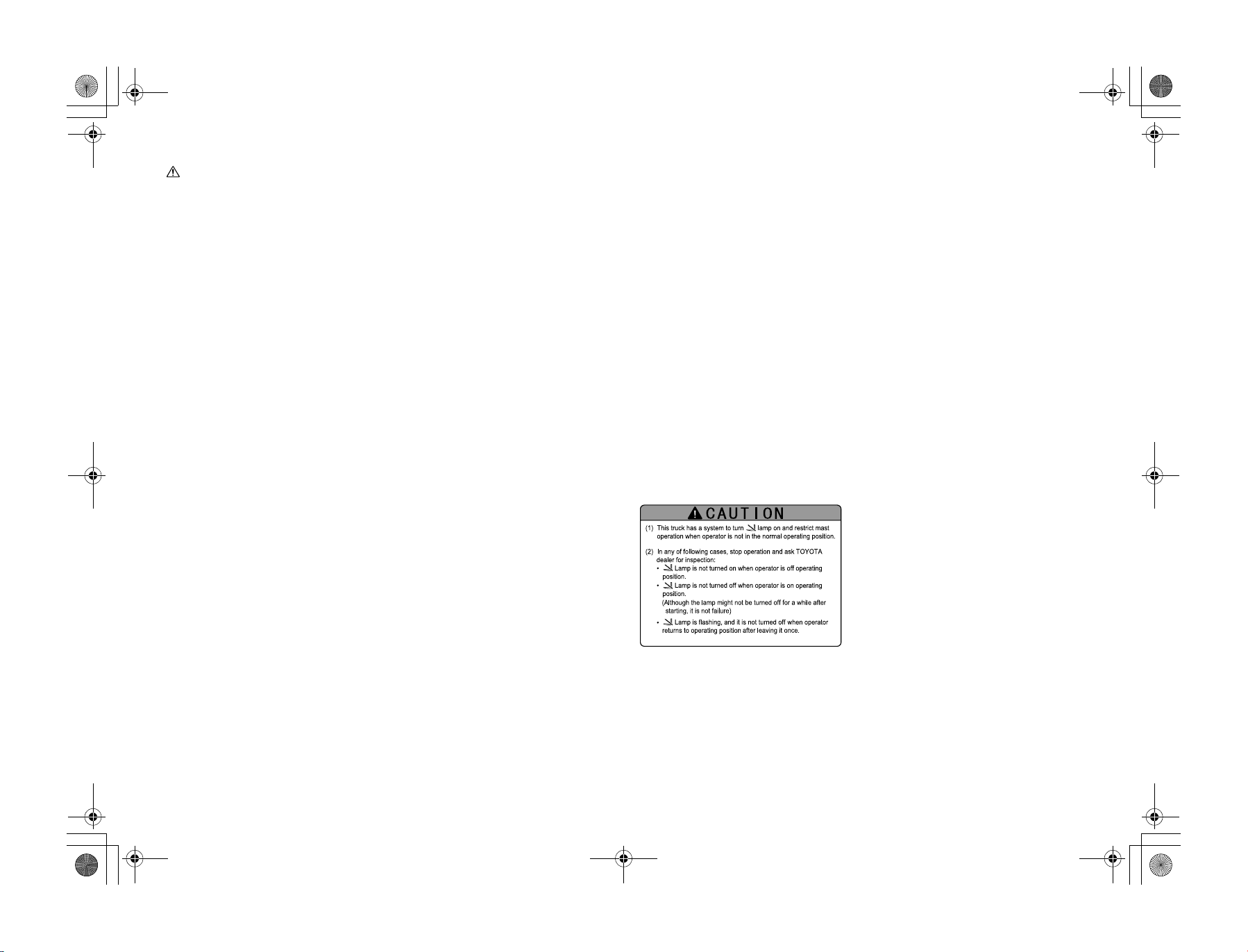
This forklift is equipped with an OPS (Operator
Presence Sensing) System. Before operating the
forklift, check that each of the System’s functions is working correctly.
Travel OPS Functions
If the operator leaves the seat while the vehicle
is traveling, the OPS lamp will light up, and two
seconds later, traveling will be stopped. However, this does not apply the brakes to stop
travel. (If the operator returns to the normal
seating position within 2 seconds, traveling can
be continued.)
If the OPS System is activated while driving up
a slope or incline, the drive to the front wheels is
stopped and consequently the vehicle will roll
back down the slope incline. To avoid this problem, make sure to sit on the seat at all times.
If more than 2 seconds has elapsed, apply the
brakes, return the control lever to the neutral
position and sit on the seat again.
Load Handling OPS Function
Forklifts with a standard lever
If the operator leaves the seat during operations,
the OPS lamp will light up, and two seconds
later, load handling operations will be stopped.
(If the operator returns to normal seating position within 2 seconds, loading can be continued.) If the operator leaves the seat while
operating the control lever, loading can be continued for 2-4 seconds.
If load-handling OPS is activated when the lift
lever is in the lowering position, move the lever
to a position other than the lowering position
and return to the normal seated position to deactivate load handling OPS. If load-handling OPS
is activated when the lift lever is in a position
other than the lowering position, load handling
OPS is deactivated 1 second after the operator
returns to the normal seated position.
Forklifts with a mini lever/joy stick lever
(Option)
If the operator leaves the seat during load han-
dling operations, the OPS lamp will light up,
and two seconds later, load handling operations
will be stopped. (If the operator returns to the
seat within 2 seconds, load handling operations
can be continued.)
To resume load handling functions, return to the
seat and return all of the levers to the neutral
position.
OPS Operation Functions
If the operator leaves the seat, a buzzer will
sound for approx. one second (“pii”) and the
OPS lamp will light up and inform the operator
that the OPS System is active. If the operator
returns to the normal seating position, the OPS
lamp will turn off.
en-4
01_A5028-0E00_En.fm 5 ページ 2007年7月4日 水曜日 午後4時1分
Return-to-Neutral Warning
If the OPS System has caused traveling operations to stop, and the operator is re-seated while
the control lever is not returned to the neutral
position, the buzzer will sound (“pi, pi, pi...”)
indicating that the travel OPS functions has not
been deactivated.
Forklifts with a standard lever
If the OPS System has caused load handling
operations to stop, and the operator is re-seated
while the lift lever is still set in the lowering
position, the buzzer will sound (“pi, pi, pi...”)
indicating that suspension of lowering has not
been deactivated.
Forklifts with a mini lever/joy stick lever
(Option)
If the OPS System has caused load handling
operations to stop, and the operator is re-seated
without returning all load handling levers to
neutral position, the buzzer will sound (“pi, pi,
pi...”) indicating that the OPS System has not
been deactivated.
SAS/OPS Controller Abnormality
Warning
If the SAS/OPS System registers an abnormality, the diagnosis lamp will blink to inform the
operator.
If the diagnosis lamp starts blinking, the SAS/
OPS System may have malfunctioned. Park the
vehicle at a safe location and request an inspection by your Toyota dealer.
In the following cases, park the vehicle in a safe
location and have the vehicle inspected by your
Toyota dealer.
• The OPS lamp does not light up even if the
operator leaves the seat.
• The OPS lamp does not turn off even if the
operator is re-seated. (In the case of diesel
engine vehicles, the diagnosis lamp may
light up during engine warm-up after a coldstart, but does not indicate an abnormality.)
CautionCaution
When the ignition switch is turned to OFF,
and the operator has been seated for a long
period, there are the cases where the OPS
lamp blinks when the ignition switch is
turned to ON. In that case, the light will go
out by leaving the seat once and return to the
normal seated position.
The Auto Speed Control Functions
(Option)
CautionCaution
• The optional Auto Speed Control Functions limit maximum travel speed and
high speed acceleration relative to load
height and weight and reduces the
chances of tip-overs. However, this feature
will not prevent all tip-overs in all circumstances.
• According to road surface conditions and
loading operations, temporary changes in
speed limits and sense of acceleration may
be experienced.
• During operation using the inching and
brake pedal, temporary changes in speed
limitations and sense of acceleration may
be experienced.
• There are cases where the idle-up of
engine increases the vehicle speed, when
the lift lever is operated upward on the
idle conditions.
Speed limits after load lifting height
and weight sensing
(Maximum speed limiter)
When the load is in an elevated position, this
function limits the maximum speed in accordance with the weight of the load. This function
reduces instability caused by sudden stopping.
Note:
• Although the maximum speed limiter will be
deactivated when the load is lowered, sudden accelerations will remain limited until
the accelerator pedal is re-engaged.
• If the load height is raised when the speed
limit is exceeded, the speed will be gradually
reduced until the set speed limit is reached.
(Auto speed control indicator)
Auto speed control indicator will be displayed
to inform the operator the speed limit after load
lifting height and weight sensing is in operation.
Load height and weight sensors to
prevent sudden acceleration
(Acceleration limiter)
When the load is in an elevated position, this
function limits sudden acceleration of the vehicle in accordance with the weight of the load.
(Preventing sudden starts)
When the load is in an elevated position at a
high engine rev, this function will suppress the
sudden acceleration of the vehicle and resultant
loss of the load even if the vehicle is operated
erroneously such as by abruptly releasing the
brake pedal or the inching and braking pedal
while the accelerator pedal is engaged, or by
setting the control lever in forward or reverse
direction.
(Loading priority function)
If you depress the clutch and brake pedal when
the load height and weight sensors to prevent
sudden acceleration in operation or when the
control lever in neutral and re-press the accelerator only if below constant speed, this function
will release the Maximum speed limiter and the
Acceleration limiter to reduce the impact of
loading.
(Function on/off indicator)
When the load height and weight sensors to prevent sudden acceleration in operation and the
speed limits after load lifting height and weight
sensing is de-active, the function on/off indicator will be displayed to inform the operator.
Low speed setting
When the low speed setting switch is pressed,
traveling will not be possible at the preset speed
or greater.
Pressing the low speed setting switch again will
deactivate this function.
Maximum speeds can be set between approximately. 8-15 km/h.
Note:
• Depending on the vehicle weight, the set
speeds may not be attained while traveling
uphill. Similarly, the set speed may be
exceeded during downhill travelling, but
will resume at the set speed when it is
reached after going down the hill.
• When a maximum speed limit has also been
set, the lower speed setting will take precedence.
• Depending on road surface changes and the
vehicle conditions, the set speed may be
exceeded temporarily.
• When setting the maximum speed, consult
your supervisor or a Toyota dealer.
en
en-5
01_A5028-0E00_En.fm 6 ページ 2007年7月4日 水曜日 午後4時1分
Maximum speed limit
This function prevents the vehicle from traveling at a faster speed from that speed preset by
your supervisor or company. The maximum
speed can be set between approximately. 815km/h.
Note:
• Depending on the vehicle weight, the set
speed may not be attained while traveling
uphill. Similarly, the set speed may be
exceeded during downhill travelling, but
will resume at the set speed when it is
reached after going down the hill.
• Depending on road surface changes and the
vehicle conditions, the set speed may be
exceeded temporarily.
• When setting the maximum speed, consult
your supervisor or a Toyota dealer.
Increasing the idling lifting speed
When the lift lever is raised, the forks can be
raised at a steady speed without pressing on the
accelerator pedal to increase the engine rev.
Note:
• There are circumstances where the idle-up of
engine increases the vehicle speed when the
lift lever is operated.
• The lifting speed will differ depending on
the vehicle model, specifications, and load
conditions.
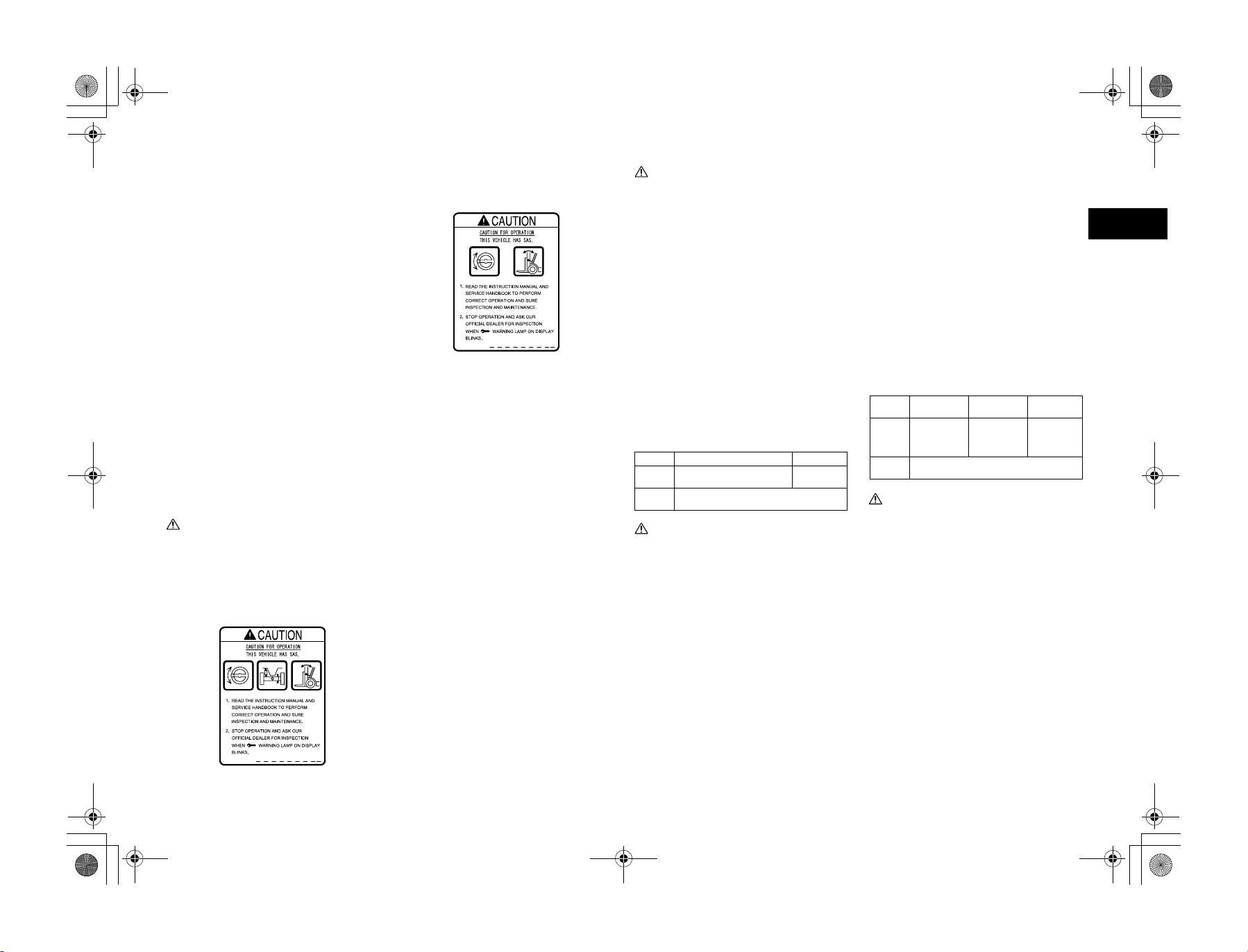
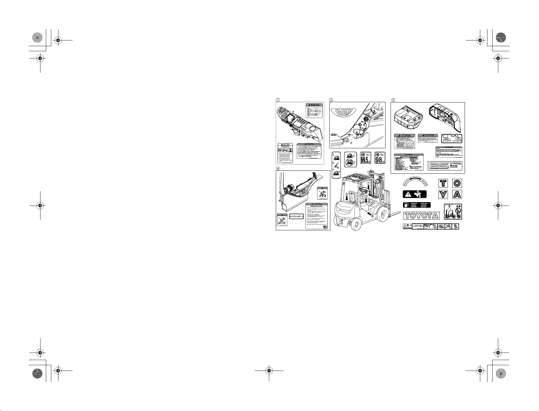
CAUTION PLATES
Caution plates are attached on a vehicle. Before driving it, please be sure to read them thoroughly.
(The sample shows those of an English version.)
en-6
01_A5028-0E00_En.fm 7 ページ 2007年7月4日 水曜日 午後4時1分
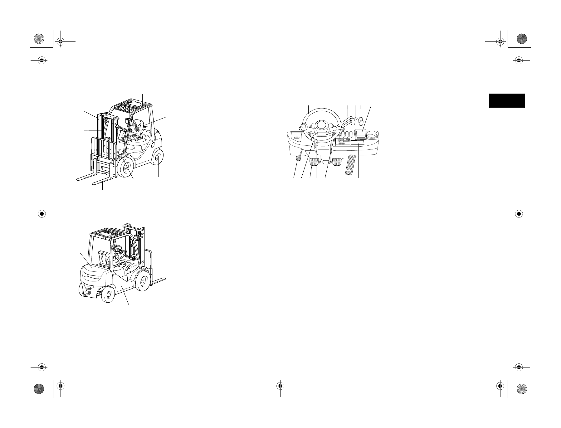
MAIN COMPONENTS
8
1
2
4
3
13
9
5
12
1. Mast
2. Chain
3. Forks
4. Tilt cylinder
7
5. Rear axle
6. Engine hood
7. Operator’s seat
8. Head guard
6
9. Counter weight
10. Frame
11. Front axle
12. Lift cylinder
13. Steering wheel
DRIVING CONTROLS AND INSTRUMENT PANEL
1. Control lever
2. Steering wheel
11623 45678
15 14 13 12 11 10 9
3. Horn button
4. Light control and turn signal switch
5. Lift lever
6. Tilt lever
7. Tilt lever knob switch
8. Multi function display (Option)
9. Combination meter
10. Accelerator pedal
11. Brake pedal
12. Ignition switch
13. Parking brake release lever
14. Inching and brake pedal
15. Tilt steering adjust lever
16. Parking brake pedal
en
10 11
en-7
01_A5028-0E00_En.fm 8 ページ 2007年7月4日 水曜日 午後4時1分
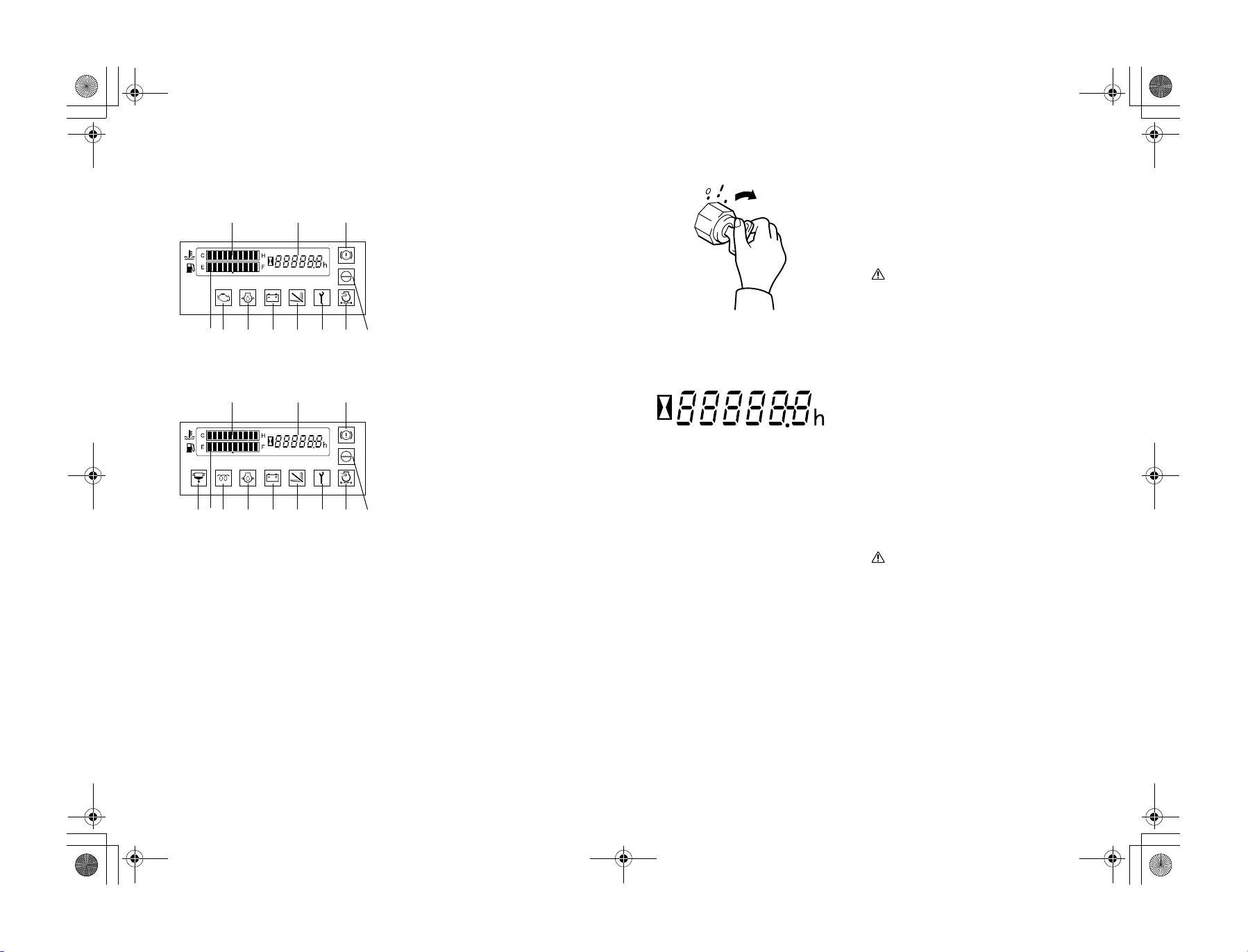
INSTRUMENTS
1
56 8 9
Gasoline engine models
1
457 8 9
Diesel engine models
23
10
23
10
Combination meter
(1)
Meters and warning lamps are arranged as
shown in the left figures.
1. Water temperature gauge
2. Hour meter
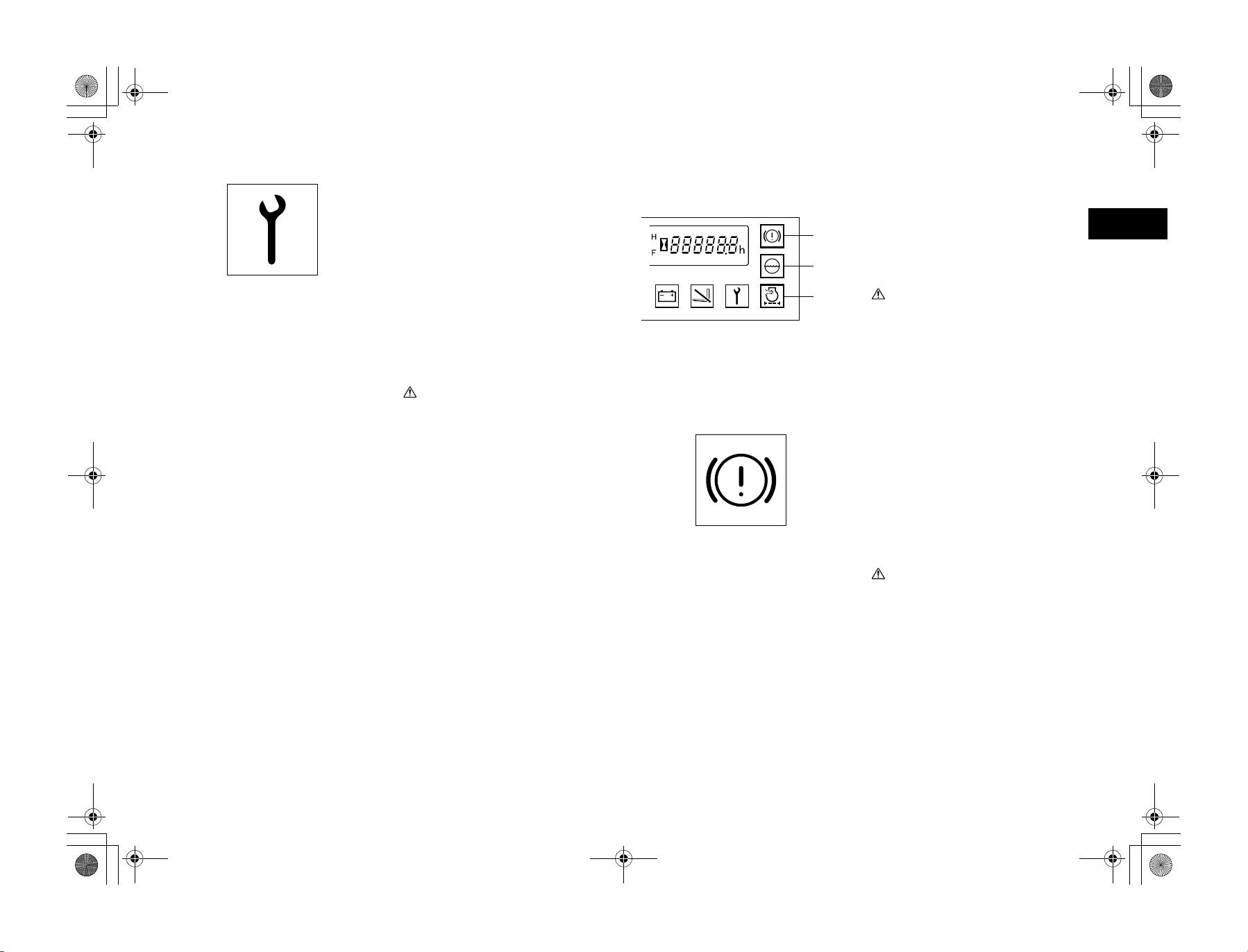
3. Brake warning lamp
(OK monitor: Option)
4. Sedimenter warning lamp
(Diesel engine models)
11
12 13
11
12 13
5. Fuel gauge
6. Engine check lamp
(Gasoline engine models)
7. Glow indicator lamp
(Diesel engine models)
8. Engine oil pressure warning lamp
9. Charge warning lamp
10. OPS lamp
11. Diagnosis lamp
12. Air cleaner warning lamp
(OK monitor: Option)
13. Coolant level warning lamp
(OK monitor: Option)
(1) Start
Warning lamp check method
Please check if all warning lamps come on
when the ignition switch is turned to ON.
Note:
Use the light control switch to check the meterlighting lamp.
Caution
Caution
• The glow indicator lamp (Diesel engine
models) is only on for 2 seconds when the
engine coolant temperature exceeds
50°C.
• If a lamp does not light up, contact your
Toyota dealer to request an inspection.
Hour meter also serving as diagnosis indicator
The hour meter operates when the ignition
switch is turned to ON. It indicates the total
number of vehicle operating hours.
The unit of the right most digit is 1/10 hour.
Please use this meter for the timing of periodic
maintenance and recording the operation
hours.
When an abnormality occurs to the vehicle
(diagnosis lamp lights up or blinks) the error
code and hour meter will be alternately displayed.
Caution
Caution
Should an error code be displayed, park the
vehicle in a safe location and contact your
Toyota dealer to request an inspection.
en-8
01_A5028-0E00_En.fm 9 ページ 2007年7月4日 水曜日 午後4時1分
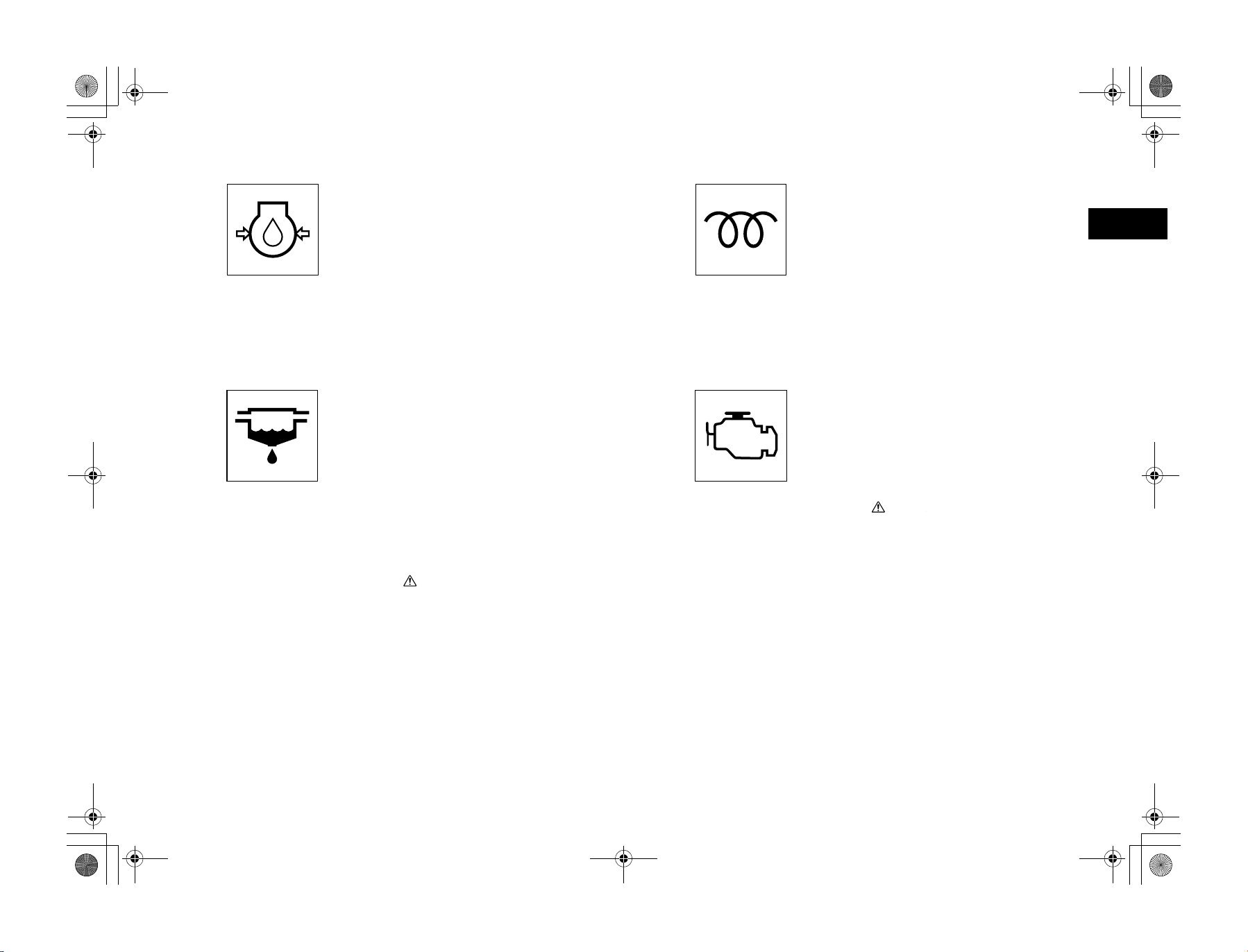
Engine oil pressure warning lamp
Comes on to indicate low engine oil pressure
while the engine is running.
1. If normal, the lamp comes on when the
ignition switch is turned to ON and goes
off when the engine starts.
2. If the lamp comes on while the engine is
running, either the engine oil is low or the
lubrication system is faulty. Stop the
operation immediately and ask a Toyota
dealer for inspection and repair.
Note:
The “engine oil pressure warning lamp” does
not indicate the oil level. Check the oil level
using the oil level gauge before starting work.
Sedimenter warning lamp
(Diesel engine models)
The sedimenter is a device for separating water
from the fuel.
1. The warning lamp comes on to indicate
water in the sedimenter exceeds the predetermined level while the engine is running.
2. If normal, the lamp comes on when the
ignition switch is turned to ON and goes
off when the engine starts.
3. If the lamp comes on while the engine is
running, drain water immediately. (See
the self service section for the draining
instructions.)
Glow indicator lamp
(Diesel engine models)
Indicates heating of glow plugs.
When the ignition switch is turned to ON, the
lamp comes on and glow plug heating begins.
The lamp goes off automatically when glow
plug heating is complete. The engine will start
easily once the glow plugs are heated.
Note:
The glow indicator lamp is on for 2 seconds
when the engine coolant temperature exceeds
50°C.
Engine check lamp
(Gasoline engine models)
1. When an error occurs to the engine controller, the display will light up to inform
the operator.
2. When condition is normal, the lamp will
light up when the ignition switch is
turned to the ON position. The lamp will
turn off when the engine is started.
CautionCaution
If the engine check lamp lights up during
operation, stop operations and park the
vehicle in a safe location, ask your Toyota
dealer to perform an inspection.
en
CautionCaution
Continued operation with the lamp on may
cause seizure of the injection pump and
pump damage. If the warning lamp lights
up, always make sure to drain the water.
en-9
01_A5028-0E00_En.fm 10 ページ 2007年7月4日 水曜日 午後4時1分
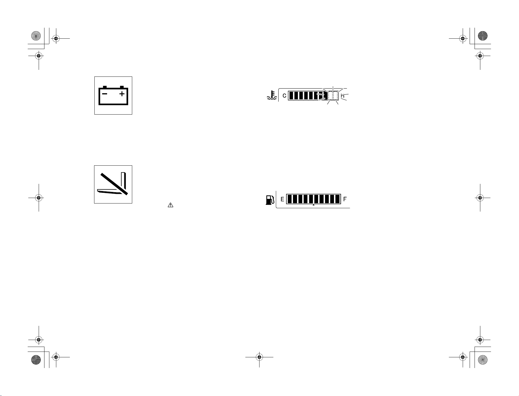
Charge warning lamp
1. This lamp comes on to indicate an abnormality in the charging system while the
engine is running.
2. If normal, the lamp comes on when the
ignition switch is turned to ON and goes
off when the engine starts.
3. If the lamp comes on while the engine is
running, stop immediately, park the vehicle in a safe location, stop the engine and
after the engine has cooled down inspect
the fan belt for cuts or looseness, adjust it,
and restart the engine.
If lamp does not go off, the electrical system may be faulty.
Please ask a Toyota dealer immediately
for inspection and repair.
OPS lamp
If the operator leaves the seat, the OPS lamp
will light up, indicating that the OPS System is
operating. (If the operator returns to normal
seating position within 2 seconds, loading can
be continued.) In such a situation, return the
control lever and lift lever to the neutral position, then sit on the seat again.
CautionCaution
In the following cases, a malfunction may
have occurred to the OPS System. Park the
vehicle in a safe location and contact your
Toyota dealer to request an inspection.
• If the operator leaves the seat, the OPS
lamp does not light up.
• Even when the operator re-seats, the OPS
lamp does not turn off.
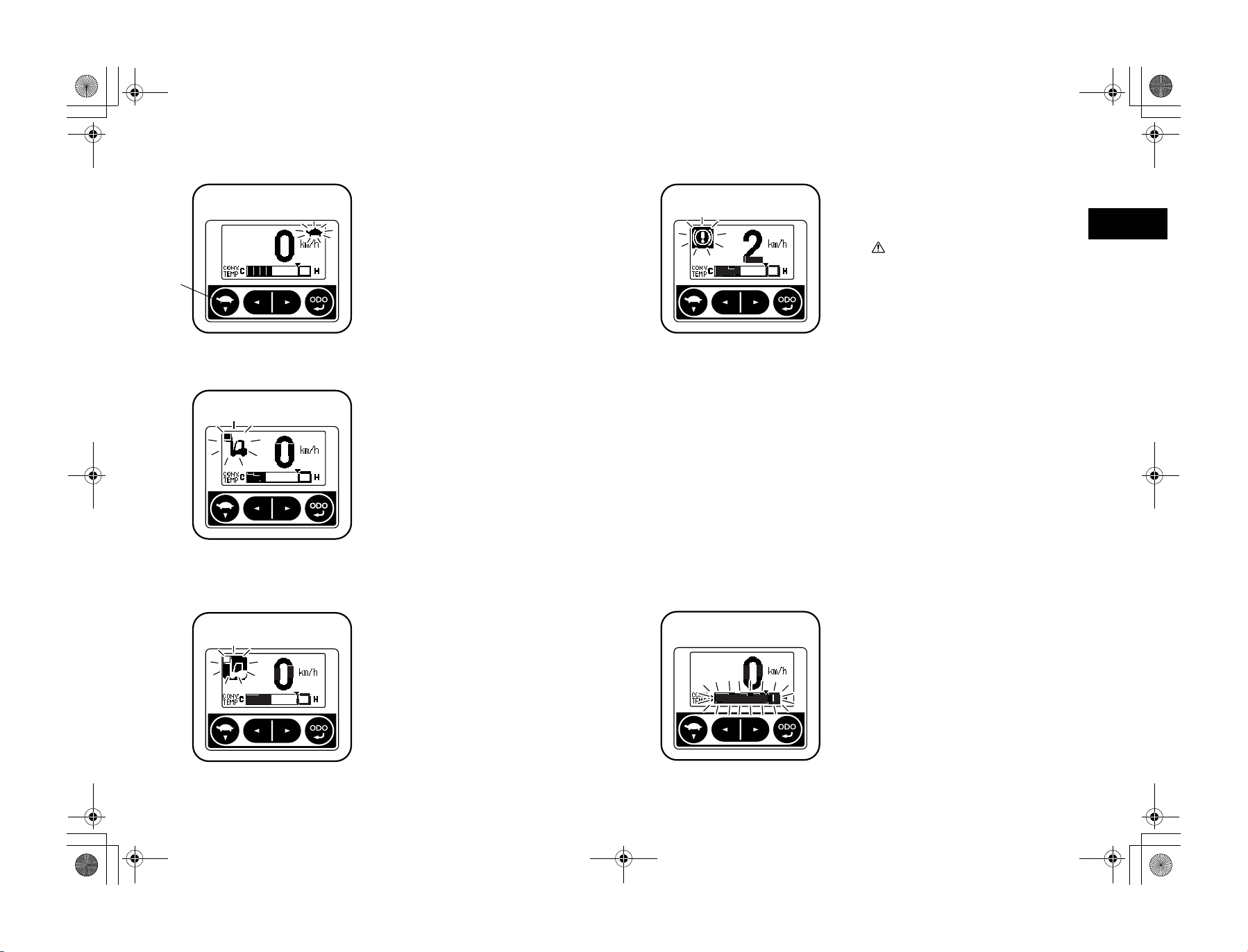
Water temperature gauge
Indicates the temperature of the engine coolant.
1. This gauge functions with the ignition
switch ON, and displays the coolant
water temperature from left to right in a
10-stage gradation scale.
2. The operator will be notified when the
water temperature is 115ºC or over
(above 8th stage), as the final two stages
at far right begin blinking. Again, when
the engine protection function activates
(for vehicles with Multifunction display:
Option), the entire gauge will start blinking to inform the operator.
3. Temporary overheating may be caused by
coolant leakage, low engine coolant level,
loosened fan belt, or other problem in the
cooling system. Contact your Toyota
dealer to request an inspection.
Fuel gauge
(Excluding LPG models)
Indicates the amount of remaining fuel in the
fuel tank in terms of a 10-stage gradation scale.
The operator will be notified that remaining
fuel level is low when the two stages at far left
start blinking.
It takes some time for the indication to be stabilized after refuelling and the ignition switch
is turned to ON.
Note:
• If the operating area is not level, atten-
tion must be paid because the correct
level may not be indicated.
• When the gauge begins blinking, refuel
as soon as possible.
• In case of diesel engine, be sure to refuel
it before it runs out because when this
occurs it becomes necessary to bleed air
from the fuel supply system.
en-10
01_A5028-0E00_En.fm 11 ページ 2007年7月4日 水曜日 午後4時1分
Diagnosis lamp
If an abnormality is registered by the SAS,
OPS, mini lever, or Auto speed control, the
respective lamps will light up or blink to
inform the operator and the diagnosis error
code will be displayed in the hour meter display area.
If the following conditions occur to the lamp,
there may be a system abnormality. Contact
your Toyota dealer to request an inspection.
• The lamp does not light up when the ignition switch is turned ON.
• The lamp lights up when ignition switch is
turned ON and stays ON.
• The lamp blinks during ignition switch is
turned ON.
CautionCaution
• Continuing to use the vehicle while the
diagnosis lamp is lighted or blinking
may lead to a breakdown. When the
lamp lights up or blinks, halt all operations and park the vehicle in a safe location. Contact your Toyota dealer to
request an inspection. (In the case of diesel engine vehicles, the diagnosis lamp
may light up during engine warm-up
after a cold-start, but does not indicate
an abnormality.)
• If the operator remains seated for a long
period with the ignition switch turned to
OFF, the next time the ignition switch is
turned to ON, the diagnosis lamp may
start blinking. If this occurs, leave the
seat. The diagnosis lamp will then turn
off.
(1) Brake warning lamp
(2) Coolant level warning lamp
(3) Air cleaner warning lamp
(1)
(2)
(3)
OK monitor (Option)
Senses the engine coolant level, brake fluid
level, clogged air cleaner element and parking
brake status. The lamp comes on to indicate a
problem. If the lamp comes on when the ignition switch is on (irrespective of the engine
speed), the corresponding part may be abnormal. Contact your Toyota dealer to request an
inspection.
CautionCaution
Always perform pre-operation checks. Do
not rely on the OK monitor, even if it is not
lit.
Brake warning lamp
When the parking brake is engaged or brake
liquid is low, the warning lamp will light up to
notify the operator.
1. The warning lamp will light up when the
parking brake is engaged. After disengaging the brake to operate the vehicle,
check to make sure the warning lamp has
turned off.
2. The lamp will light up to notify the operator when the brake oil is low.
CautionCaution
• If the warning lamp does not turn off
when the parking brake is disengaged,
the brake fluid may be low. Inspect the
brake fluid level and replenish it if necessary.
• If the warning lamp remains a lighted
even if the brake fluid level is sufficient,
contact your Toyota dealer to request an
inspection.
en
en-11
01_A5028-0E00_En.fm 12 ページ 2007年7月4日 水曜日 午後4時1分
(1)
Coolant level warning lamp
1. When the coolant level of the radiator
reserve tank becomes low, the indicator
lamp will light up to notify the operator.
2. If the lamp lights up while the engine is
running, this may indicate a deficiency in
coolant. Stop the engine and inspect the
coolant level in the radiator reserve tank
and the radiator. Before checking coolant
level in the radiator wait for it to cool as it
maybe under pressure when hot.
Note:
Even if the coolant level warning lamp is not
lighted, always inspect the coolant level before
starting operations.
Air cleaner warning lamp
1. This lamp comes on when the air cleaner
element gets clogged while engine is running.
2. If normal, the lamp comes on when the
ignition switch is turned to ON and goes
off when the engine starts.
3. If the lamp comes on while the engine is
running, stop operations and park the
vehicle in a safe location, stop the engine
and clean the element and dust cup. For
the cleaning method, refer to the Weekly
Inspection Section in this manual.
Brake warning lamp
(Wet brake models)
If the wet brake function is abnormal, the
warning lamp will light and warning buzzer
will sound to inform operator. When the warning lamp lights and buzzer sounds, cease work
operation and stop the vehicle in a safe place.
Securely set the parking brake and fully
depress the brake pedal until buzzer stops with
the engine still running. After confirming that
buzzer is turned off and warning lamp goes off,
restart the work operation.
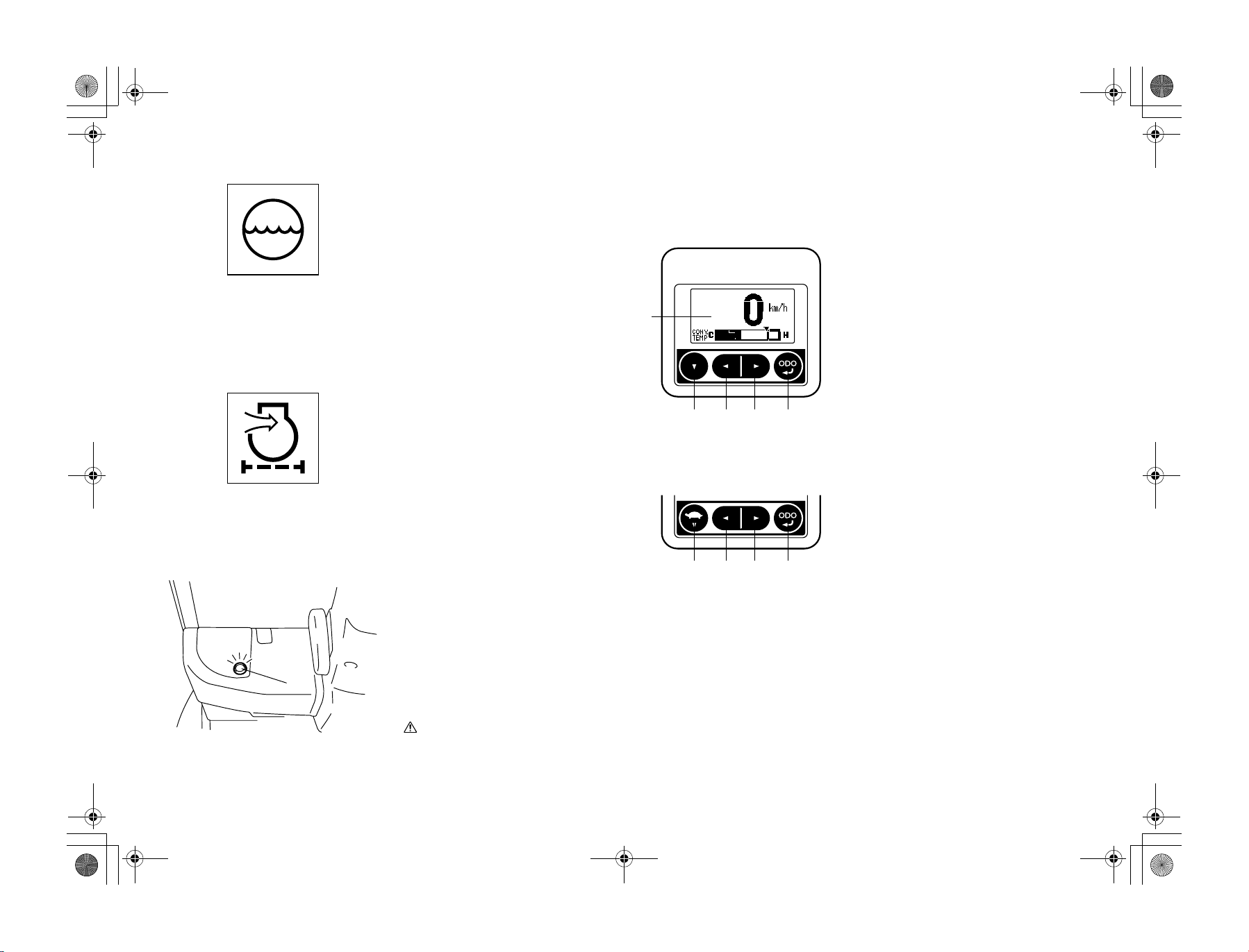
MULTIFUNCTION DISPLAY (OPTION)
1. Multifunction display area
(Multifunction display)
(Multifunction display DX)
1
2 3 4 5
(Multifunction display DX:
Vehicles with Auto speed control)
6 3 4 5
2. Down switch
3. Left switch
4. Right switch
5. Meter display switch
6. Low speed setting switch (Only for DX
models with Auto speed control)
(1) Brake warning lamp
en-12
CautionCaution
If the warning lamp does not go off or
buzzer does not stop even when the brake
pedal is depressed, ask a Toyota dealer for
an inspection.
01_A5028-0E00_En.fm 13 ページ 2007年7月4日 水曜日 午後4時1分
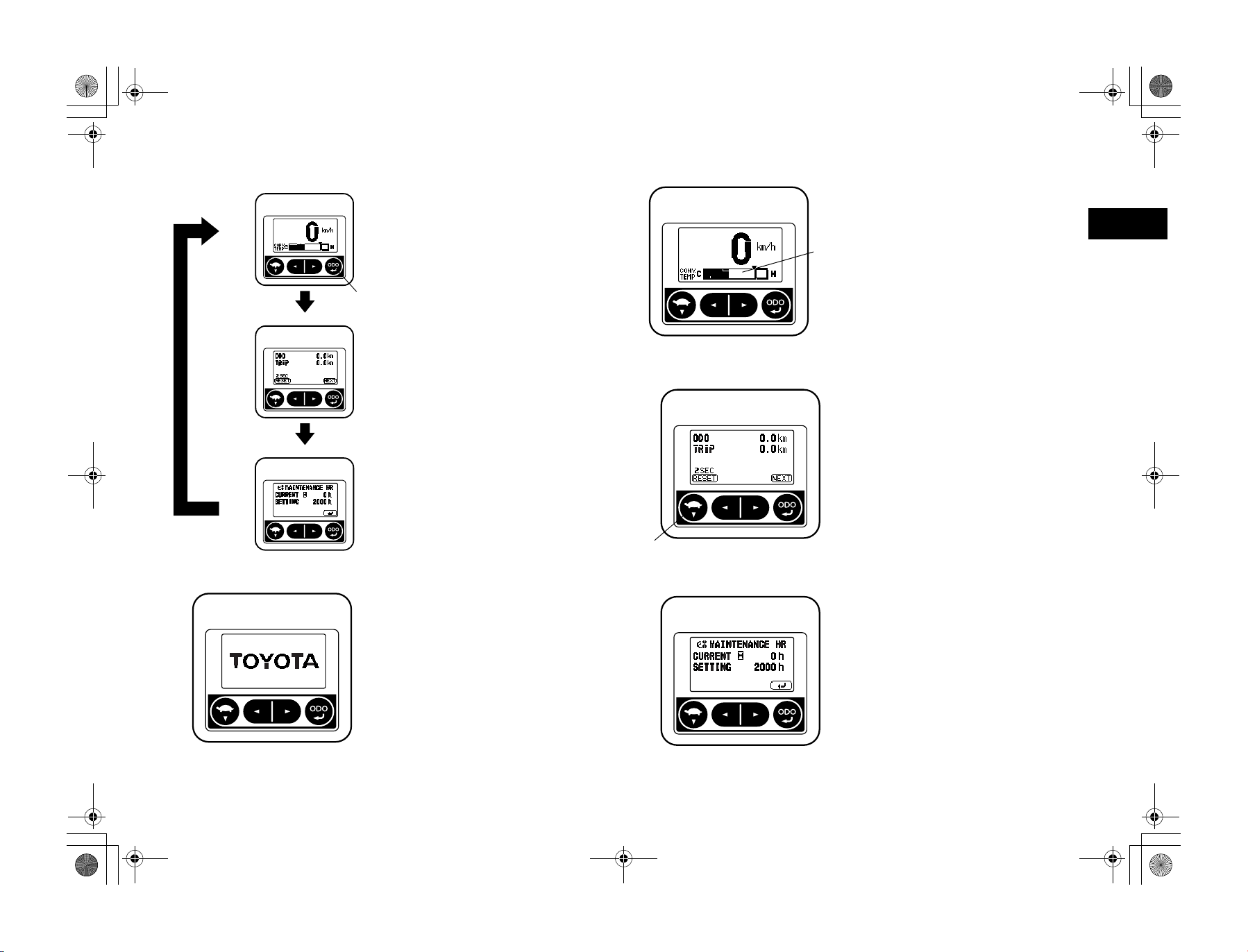
Digital speed meter display
ODO • TRIP Meter display
Maintenance display
(1) Meter display switch
(1)
DISPLAY SCREEN TABLE
From the standard screen display, pressing the
meter display switch will change the display
between ODO, TRIP, and Maintenance Hour
Meter display screens.
Note:
Always operate the switch panel with your finger tips and when the vehicle is stopped.
Start screen
When the ignition switch is turned to ON, the
start screen will appear for 1 second.
Note:
BT Specification (Option) will not display
anything for 1 second when the ignition switch
is turned to ON.
(1)
(1) Torque converter oil temperature gauge
(1)
(1) Low speed setting switch or down switch
Standard screen
Vehicle speed is digitally indicated in km/h at
the top of the screen. At the bottom of the
screen, torque converter oil temperature is
indicated in a 10-stage level.
ODO • TRIP meter
ODO......... Displays the total distance traveled.
TRIP......... After resetting this function, dis-
Note:
• Pressing the low speed setting switch (DX
• Always operate the switch panel with your
plays the total distance traveled
until now.
models with Auto speed control) or the
down switch for more than 2 seconds will
reset the total travel distance.
finger tips and when the vehicle is stopped.
Maintenance hour meter
Displays the set value and current value of the
maintenance hour meter.
CURRENT...............Displays the current time.
SETTING.................Displays the maintenance
The maintenance hour meter time setting can
be set between 10-2000 hours. 10-200 hours
setting can be set in 10 hour intervals, and 2002000 hours setting can be set in 50 hour intervals.
Note:
To change the time setting, consult your supervisor or Toyota dealer.
hour time setting.
en
en-13
01_A5028-0E00_En.fm 14 ページ 2007年7月4日 水曜日 午後4時1分
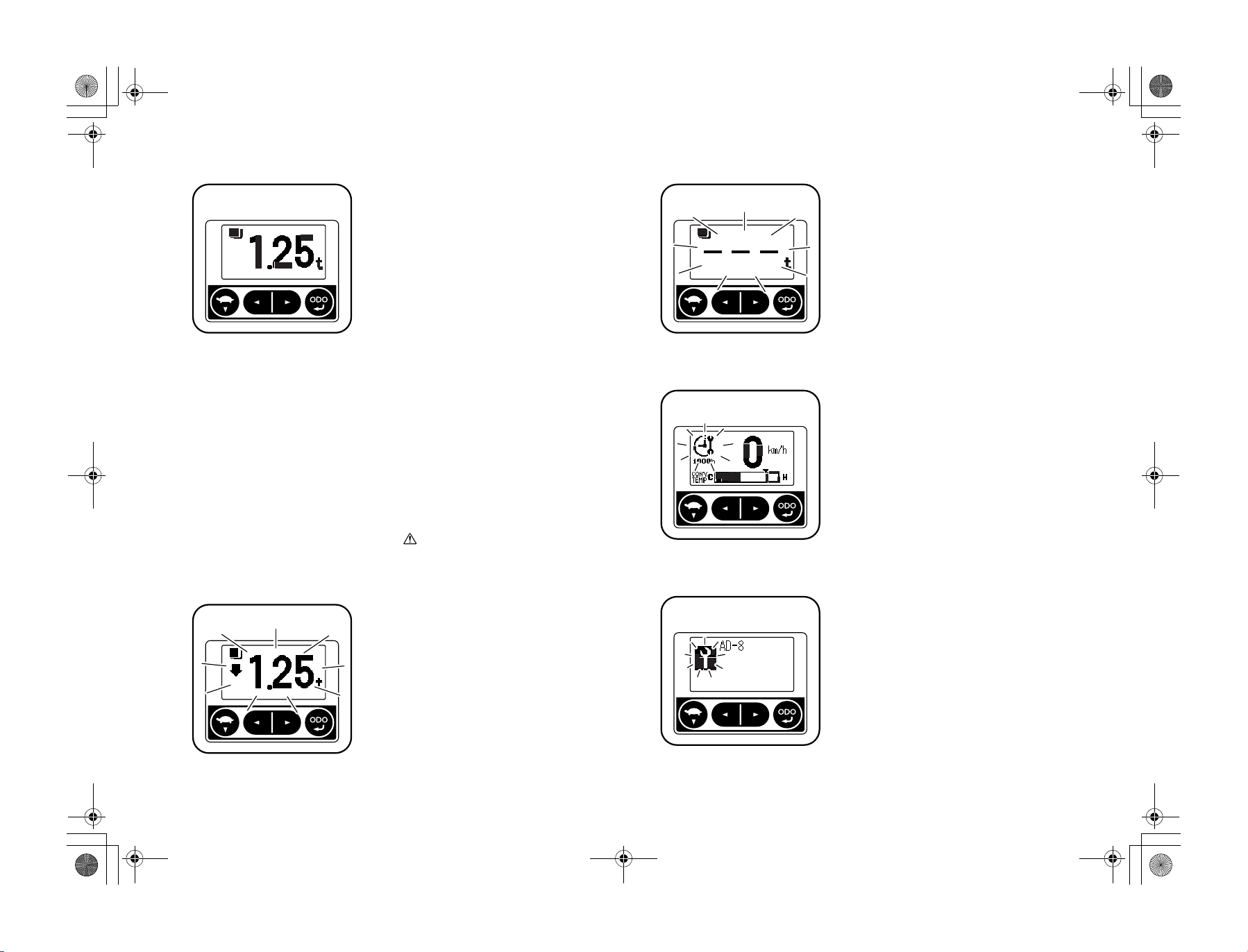
Load meter
(Only with DX models)
Pressing the lift lever knob switch or the load
meter switch (mini lever models) will allow
the operator to confirm the weight of the load
being handled.
Note:
In the case of joy stick models (Option), the
load meter switch and fork automatic leveling
control switch functions are combined.
1. Adjust the load to a height of 500mm
above ground level and set the mast vertical.
2. In the standard screen, press the lift lever
knob switch or the load meter switch
(mini lever models).
Note:
• For each operation, the meter reading will
display for 3 seconds. (the display will
remain indicated while the switch is held
down).
• Pressing the lift lever knob switch or the
load meter switch (mini lever models)
while the vehicle is traveling will not display the load display screen.
• If the load is less than 100kg, the meter will
indicate 0.00t.
CautionCaution
This function should be used as reference
when conducting handling operations, and
not used in business dealings or as proof.
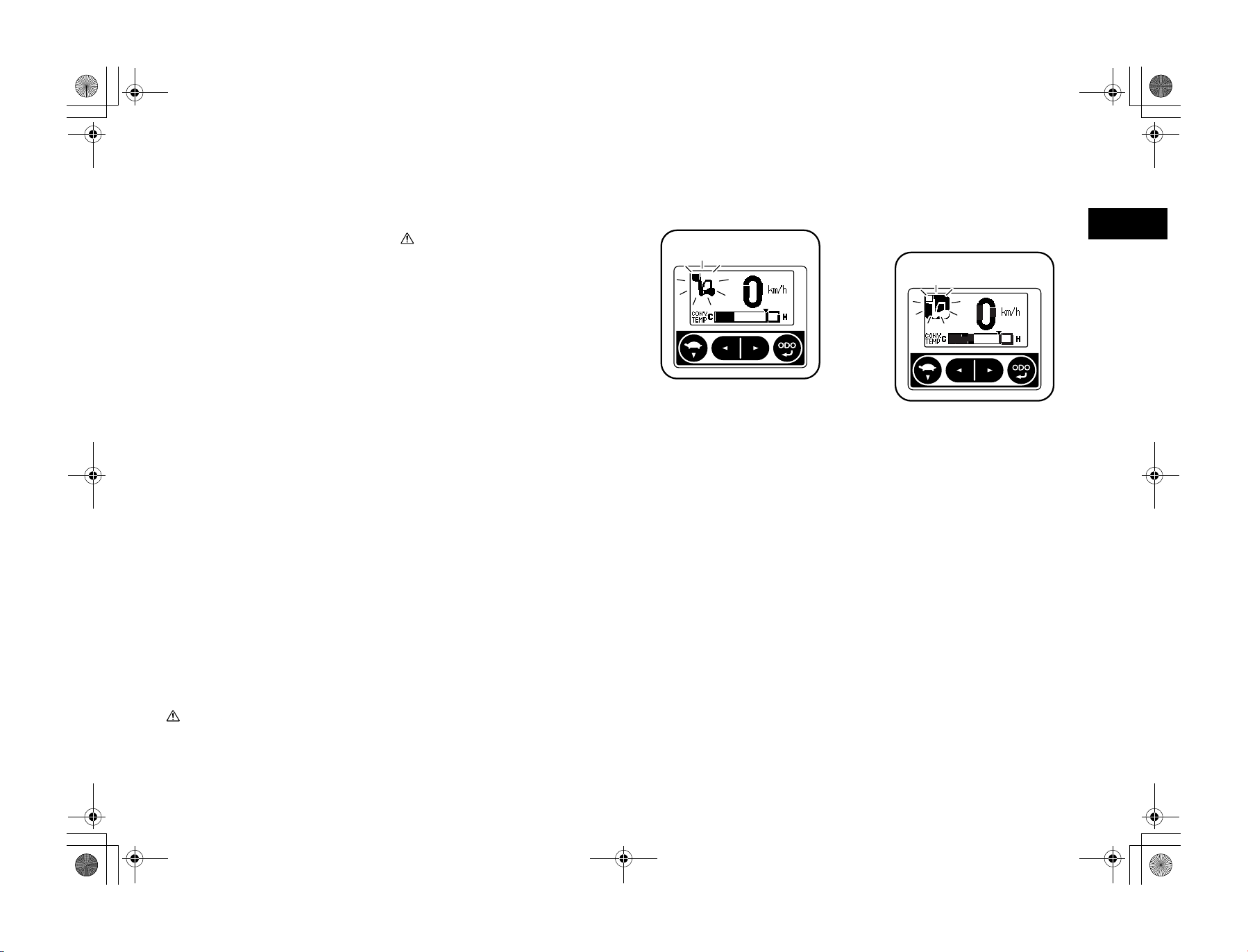
Load meter error display
When the load meter is operated while the load
is in an elevated position, an arrow will appear
at screen left and the measured weight indication will blink to notify the operator that the
reading is inaccurate.
To measure the load, always set the load to a
height of approximately 500mm above ground
and set the mast vertical.
Note:
If 0 is slightly deviated toward the minus side,
the display will indicate -0.00 t.
Load meter sensor error display
When the load meter sensor malfunctions, the
display will blink as indicated in the diagram at
left.
Note:
When the load meter sensor blinks to indicate
an error, contact your Toyota dealer to request
an inspection.
Maintenance indicator
When the reset maintenance time occurs, the
operator will be notified through the display
and a warning sound. Conduct necessary maintenance.
Note:
The maintenance time setting should be determined by the supervisor. For information on
setting the maintenance time, contact your
supervisor or Toyota dealer.
Diagnosis indicator
If an abnormality is registered within the Multifunction display, the operator is notified
through a warning sound together with diagnosis error content display.
Note:
• The error code display will be different
depending on the abnormal area and nature
of the abnormality. There are also occasions when the error is not indicated
depending on the area of abnormality.
• When the diagnosis indicator is displayed,
contact your Toyota dealer to request an
inspection.
en-14
01_A5028-0E00_En.fm 15 ページ 2007年7月4日 水曜日 午後4時1分
(1)
(1) Low speed setting switch
Low speed setting indicator
(Only for DX models with Auto
speed control)
When low speed settings have been set, the
turtle mark is displayed.
Each time the low speed setting switch is
pressed, the turtle indicator will light up. When
the indicator is lighted, the low speed setting
control is active.
Note:
Always operate the switch panel with your finger tips.
Auto speed control indicator
(Only for DX models with Auto
speed control)
When the load height and weight sensors to
prevent sudden acceleration or the speed limits
after load lifting height and weight sensing are
in operation, the auto speed control indicator is
displayed to inform the operator.
Function on/off indicator
(Only for DX models with Auto
speed control)
Even when the speed limits after load lifting
height and weight sensing is deactivated, the
operator is notified via display indication that
the preventing sudden starts function is active.
Parking brake on warning
When the parking brake is engaged while the
lift vehicle is traveling, the warning indicator
will blink and a warning will sound to notify
the operator.
CautionCaution
• If the vehicle is operated without disengaging the parking brake, the brake will
lose effectiveness. Contact your Toyota
dealer to request an inspection.
• If the indicator lamp does not turn off
even when the parking brake is disengaged, stop operations and contact your
Toyota dealer to request inspection.
Parking brake off warning
When the ignition switch is turned to OFF or
the operator leaves the seat while the parking
brake is disengaged, a warning sound will
warn the operator to apply the parking brake.
The warning will also be sounded if the operator returns to the normal seated position and
turns the ignition switch to ON while the parking brake is disengaged.
Note:
• When the parking brake is applied, the
warning sound will stop.
• When leaving the driver's seat, always shift
to NEUTRAL, set the parking brake, lower
the forks, and tilt forward so the tips will
not trip pedestrians, and turn off the ignition switch.
Torque converter oil temperature
overheating warning
When the torque converter oil temperature
reaches level 9 on the indicator (120ºC or
over), the indicator will blink to notify the
operator. When the indicator reaches level 10
(140ºC or over), the entire indicator will blink
to notify the operator.
Note:
When the warning lamp blinks, park the vehicle in a safe location, engage the parking
brake, open the engine hood with the motor
idling, to assist in the cooling of the torque
converter oil.
en
en-15
01_A5028-0E00_En.fm 16 ページ 2007年7月4日 水曜日 午後4時1分
Over-speed alarm
(Only for DX models)
When the set traveling speed is exceeded, the
speed meter will blink and a warning will
sound to notify the operator.
Note:
This function does not limit traveling speed
and is an indication only. Pay attention to your
speed when operating the vehicle.
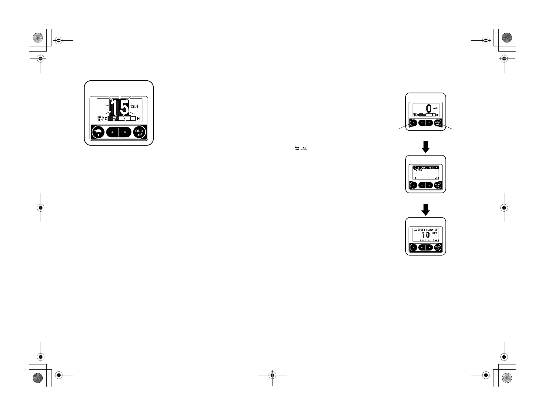
Setting menu screen
With the Multifunction display, pressing the
low speed setting switch or the down switch in
the standard screen for more than 2 seconds
will display the setting menu screen.
Note:
When the supervisor locks the menu, these
screen settings can not be displayed.
Selecting the options using the low speed setting switch or the down switch and then pressing the meter display switch will display each
screen setting.
Select [ ] in the setting menu screen,
and then pressing the meter display switch will
return to the standard screen.
Note:
Always operate the switch panel using your
finger tips.
Vehicles having Multifunction display DX
(1) (2)
<Standard screen>
<Setting menu screen>
en-16
<Over-speed alarm setting screen>
(1) Down switch
(2) Meter display switch
01_A5028-0E00_En.fm 17 ページ 2007年7月4日 水曜日 午後4時1分
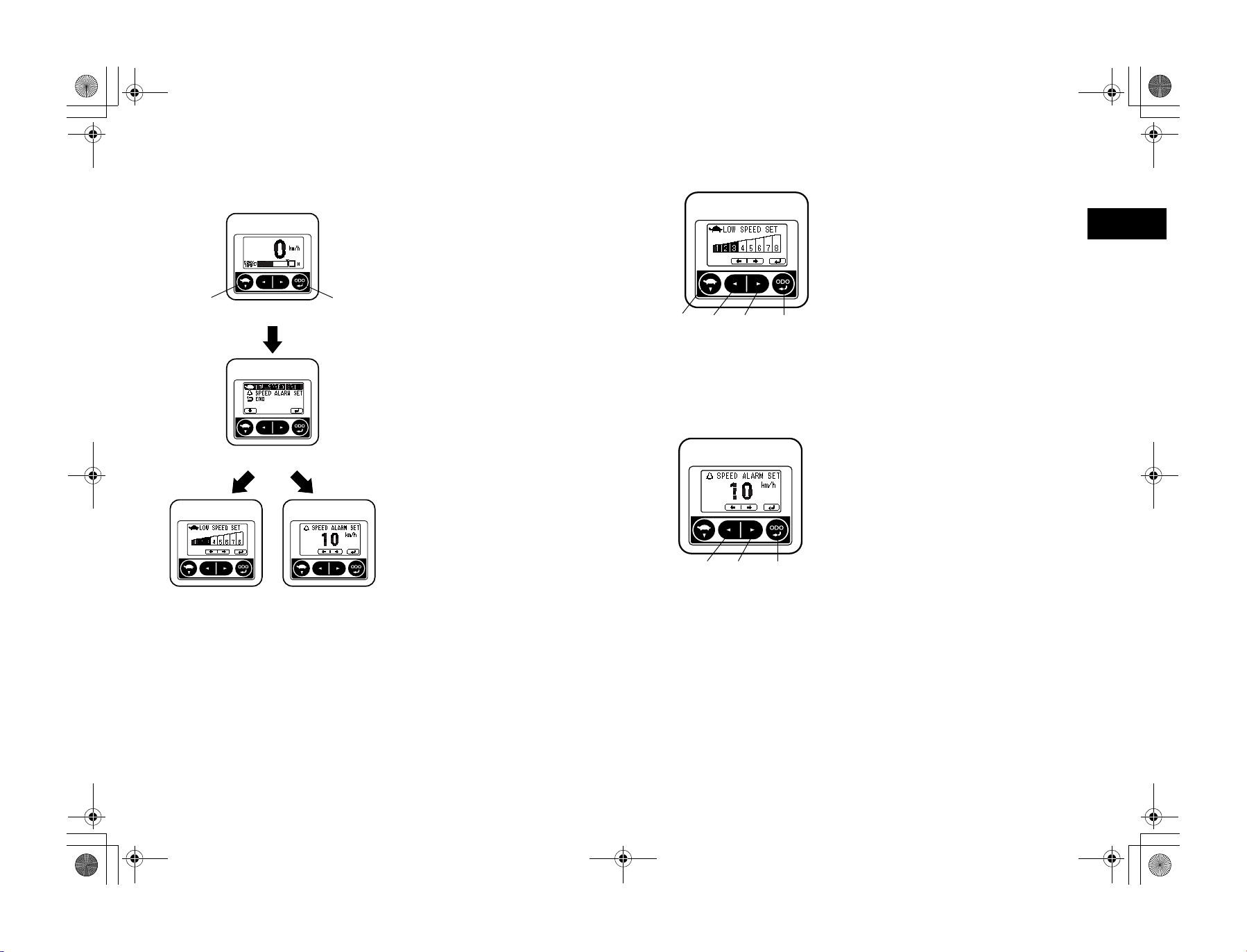
Vehicles with Auto speed control and
Multifunction display DX
(1) (2)
<Standard screen>
<Setting menu screen>
(1) (2) (4)(3)
(1) Low speed setting switch
(2) Left switch
(3) Right switch
(4) Meter display switch
(2) (3) (4)
Low speed setting screen
When the low speed settings are activated, a
range of 8 maximum speed settings can be
established.
Selecting the level 8 setting will turn off the
function.
Left switch ............. Decreases the setting level
Right switch .............Increases the setting level
Meter display switch...... Switches to the menu
screen
Note:
• If level 8 is selected, the setting cannot be
changed by pressing the low speed setting
switch or the down switch in the standard
screen.
• Always operate the switch panel using your
finger tips.
Over-speed alarm setting screen
This function allows you to set the traveling
speed which will set off the alarm.
Left switch ...................... Reduces travel speed
Right switch ...................Increases travel speed
Meter display switch...... Switches to the menu
Note:
Always operate the switch panel using your
finger tips.
screen
en
<Low speed setting
screen>
<Over-speed alarm setting screen>
(1) Low speed setting switch
(2) Meter display switch
(2) Left switch
(3) Right switch
(4) Meter display switch
en-17
01_A5028-0E00_En.fm 18 ページ 2007年7月4日 水曜日 午後4時1分
SWITCHES AND LEVERS
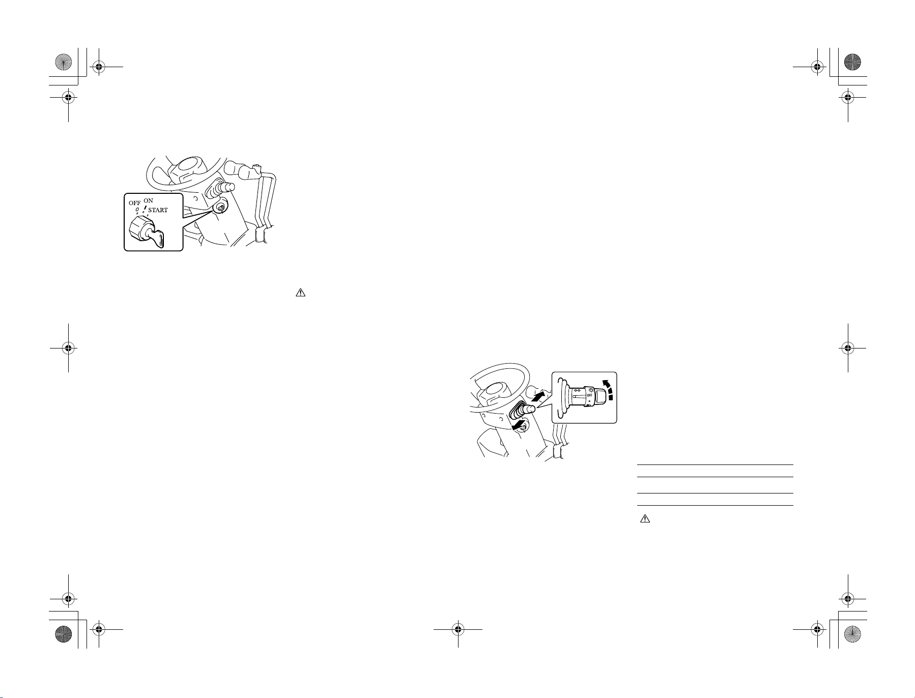
Ignition switch
{ [OFF] ....... Engine stop position.
I [ON]......... Engine operation position.
The intake heater is preheated before starting
in the diesel models.
START ............ Engine, start position. Located
After the engine starts, release the key and it
will return to the I [ON] position automatically.
In the torque converter model, the engine does
not start unless the control lever is set in the
neutral position.
CautionCaution
• Never operate the ignition switch without first sitting on the seat. Otherwise,
the forklift could start to move uncontrolled, causing an accident.
• When the OPS lamp is on, return each
lever to the neutral position and sit on
the seat.
Then confirm that the lamp has gone off.
• Do not leave the switch in the [ON] position when the engine is stopped. It may
cause over discharge of the battery.
• Do not turn the switch to the START
position while the engine is running.
• For the sake of safety it is recommended
to always start the engine of a vehicle
with the transmission gear shift lever
shifted in the neutral position.
• Do not operate the starter motor for
more than 30 seconds continuously.
Return the switch to the [OFF] position
and wait at least 30 seconds prior to
attempting restart.
• In case of the anti-restart ignition switch
(optionally available), be sure to shift the
switch to the [OFF] position before
attempting to start the engine again.
Key insertion and withdrawal
are performed in this position.
Located one position clockwise from { [OFF] position.
one position clockwise from
the I [ON] position.
(2)
(1) Left turn
(2) Right turn
(1)
• With the ignition switch OFF (engine
off), the forks will not lower even if the
lift lever is operated. However, if you sit
in the seat and turn on the ignition
switch, you can lower the forks. (Except
mini lever models) Do not operate the lift
lever before getting on the vehicle and
starting up the engine. (key-off, lift
locked)
• If the diagnosis lamp does not go off even
when the operator sits on the seat, the
battery power may be low. In such a
case, do not drive the vehicle until the
lamp goes off, otherwise the vehicle may
not operate correctly. If you are obliged
to drive the vehicle, do so with the
utmost care. Also, stop driving and ask a
Toyota dealer for inspection if the lamp
does not go off 1-2 minutes after the
engine starts, or when you race the
engine for a while. (For diesel vehicles,
the diagnosis lamp may be on for a while
to warm up the engine after cold starting. This is, however, not an engine malfunction or failure.)
Integrated light and turn signal
switch
This two-position switch serves as both a light
switch and turn signal switch.
Light control switch
Irrespective of a ignition switch position, this
switch allows you to turn on and off the lights.
This switch has two positions. With the switch
at each position, the light comes on as shown
below.
Lamp name Step 1 Step 2
Head lamps
Side clearance lamps, tail lamps
(Option)
Meter illumination lamp
Caution
Caution
Do not keep lights such as head lights on for
a long period when the engine is stopped. It
may cause over discharge of the battery and
make engine starting impossible.
−
{{
{{
{
en-18
01_A5028-0E00_En.fm 19 ページ 2007年7月4日 水曜日 午後4時1分
(1) Forward
(2) Reverse
(1)
(2)
Turn signal switch
Makes the turn signal lamps blink
Left turn ................................... Push forward
Right turn ................................ Pull backward
The signal switch will operate when the ignition switch is ON.
The turn signal lever returns automatically to
the original position after making a direction
change.
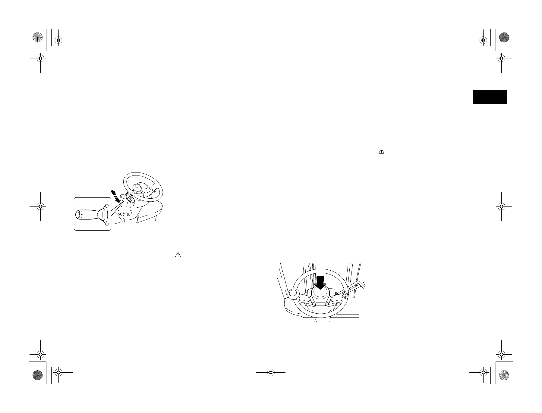
Control lever
Lever for shifting between forward and
reverse.
Forward.................................... Push forward
Reverse..................................... Pull backward
The neutral position is halfway between the forward
and reverse position.
Note:
After the OPS System operates, return the
accelerator pedal to its fully released position
and set the control lever to the neutral position,
and sit on the seat to restart driving. (Even
though the operator sits on the seat, driving is
impossible unless the control lever is in the
neutral position.)
CautionCaution
The engine cannot be started unless the control lever is in the neutral position.
Stop the vehicle before shifting between forward and reverse direction.
(1)
Torque converter interlock function
(Option)
If you switch the control lever direction to
something other than the current travel direction while moving at high speed, this function
electrically disengages the drive and sets the
torque converter to neutral. Once the speed
drops below the set speed while running in
neutral, the travel direction is automatically
switched.
To change travel direction, operate the control
lever after travel speed is reduced sufficiently.
Ask your Toyota dealer for changing speed setting.
CautionCaution
• When the interlock has engaged, release
the accelerator pedal and use the brake
pedal to reduce speed. After the vehicle
has stopped moving, slowly press the
accelerator pedal down to start moving
again. Disengaging the interlock while
the accelerator pedal is pressed down
could result in wheel spin.
• Do not perform Forward or Backward
operation on slopes. If control lever is
operated on a down slope, torque converter interlock function may not operate correctly.
Horn button
Press the button in the center of the steering
wheel to sound the horn.
The horn will sound even when the ignition
switch is OFF.
en
(1) Push
en-19
01_A5028-0E00_En.fm 20 ページ 2007年7月4日 水曜日 午後4時1分
(1) Push
(1) Lower
(2) Raise
(2)
(1)
(1)
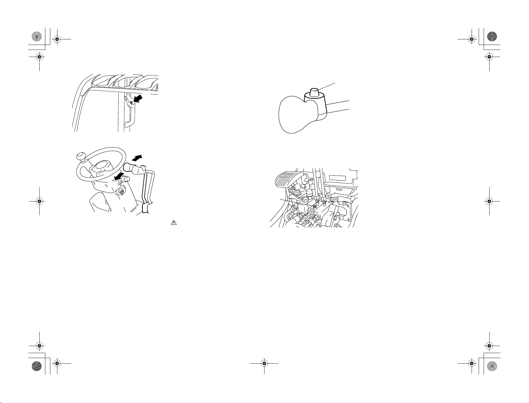
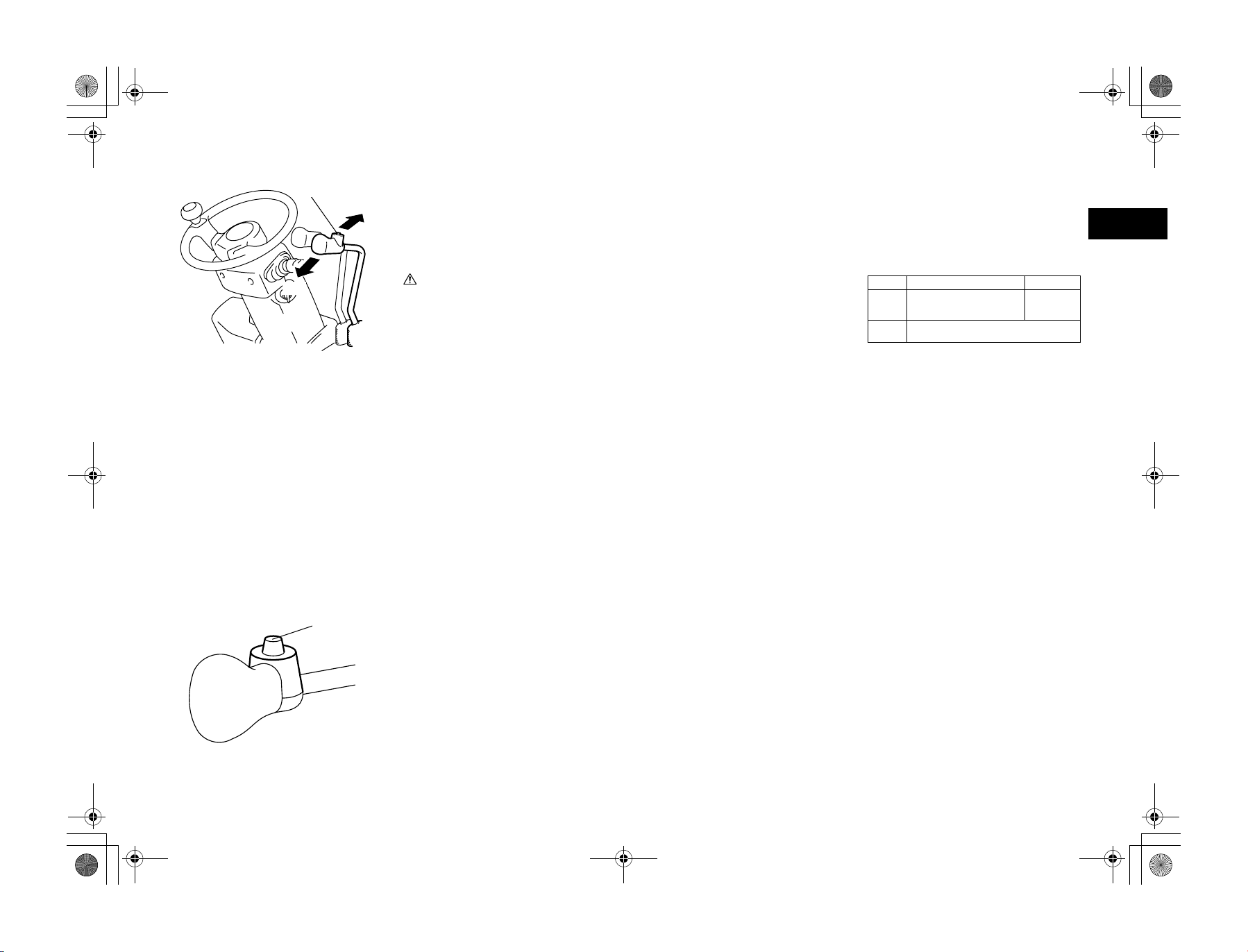
Horn button (Option)
The horn will sound when the button at the top
of the rear pillar assist grip is pressed. Use this
horn when backing up.
The horn will sound even when the ignition
switch is OFF.
Lift lever
Raises and lowers the forks.
Raise.......................................... Pull backward
Lower ......................................... Push forward
The lifting speed can be adjusted by how far
the accelerator pedal is depressed and how far
the lever is pull back.
The lowering speed can be adjusted only by
how far the lever is pushed forward.
Note:
The idling lifting speed increase function
(Option) automatically increases lifting speed
by engaging the lift lever.
CautionCaution
• After the OPS System operates, return
the accelerator pedal to its fully released
position and set the lift lever to the neutral position, and sit on the seat to restart
the operation. (If you sit on the seat
while raising the lift lever, the forks will
start to move 1 second later.)
• If you sit on the seat while lowering the
lift lever, the forks will not lower due to
the return to neutral function.
• Always operate the lift lever while correctly seated.
• When the ignition switch is turned to
OFF and lowering the lift lever, the forks
will not lower. However, if the operator
sits in the normal seated position then
the ignition switch is turned to ON, the
forks will be lower even if the engine is
off. (Except mini-lever/joy stick models)
(1) Lift lever knob switch
(1)
(1) Lift lock release bolt
(1)
Lift lever knob switch
(Option)
For vehicles with Multifunction display DX
(Option), pressing the lift lever knob switch
will display the weight of load.
Note:
• Operate this function when you are not performing loading operations.
• When weighing the load, always remember
to position the load at a height of about
500mm above the ground and make the
mast perpendicular.
Key-lift interlock
When the ignition switch is OFF, the lift will
not descend even if the lift lever is lowered.
However, if the operator sits properly in the
seat and turns the ignition switch ON, the forks
can be lowered even if the engine is off
(Except mini lever/joy stick models).
If the ignition switch cannot be turned ON for
whatever reason, loosen the manual lowering
valve located on the oil control valve beneath
the toe board, and operate the lift lever in the
downward direction.
Note:
Once the forks have been lowered with the lift
lock release bolt, close and lock the valve.
en-20
01_A5028-0E00_En.fm 21 ページ 2007年7月4日 水曜日 午後4時1分
(1) Forward tilting
(2) Backward tilting
(3) Tilt lever knob switch
(2)
(3)
(1)
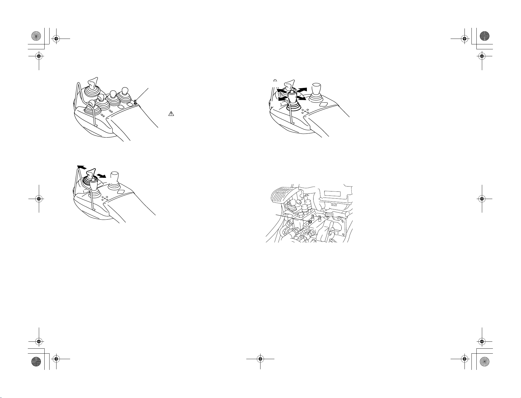
Tilt lever
Tilts the mast forward and backward.
Forward.................................... Push forward
Backward................................. Pull backward
The forward or backward tilting speed can be
adjusted by the degrees of accelerator pedal
depression and lever operating stroke.
CautionCaution
• Insure the load-handling control levers
are in their neutral positions before
returning to the operator's seat, if not
load-handling functions will start movement 1 second after operator returns to
the seat.
• Always operate the tilt lever from a
seated position.
• After the OPS System operates, return
the accelerator pedal to its fully released
position and the tilt lever to the neutral
position, and sit on the seat to restart the
operation. (If the operator sits on the
seat without returning the load-handling
control levers to their neutral positions,
load-handling functions will start movement 1 second after.)
Automatic forks leveling control
With the forks positioned at backward tilt, use
the lever to tilt the forks forward while
depressing the tilt lever knob. Then, the mast
will be automatically stopped with the forks
horizontally positioned.
Motion upon change of tilt from backward to
forward, with tilt lever knob switch pressed:
High lift Forks stopped at its horizontal
Low lift Forks stopped at its horizontal position (with mast
Not loaded Loaded
position (with mast vertically
positioned)
vertically positioned)
No forward tilt
Active mast rear tilt speed control
At a high lift height, the mast has a backward
tilt speed controller (slow down) irrespective
of the load. When lowering from a high lift
height to a lower lift height while tilting the
mast backward, the control speed will not
change.
At a low lift height, the mast can be tilted at
full speed even if there is a load. If the mast is
tilted backward at a low lift height with the tilt
knob switch pressed, the mast has the backward tilt speed controlled (slowed down) as
long as the tilt lever knob switch is pressed.
When the fork enters the upper lift height stage
from the lower one, the rear tilt speed will be
restrained as long as the automatic fork leveling control switch is depressed. If the switch is
not depressed, the fully open speed will be
applied.
en
(1) Tilt lever knob switch
(1)
Tilt lever knob switch
Depressing the tilt lever knob switch while
changing from backward to forward tilt will
automatically stop forks at their horizontal
position.
It is also possible to slow down the backward
tilt speed at a low lift height by depressing
knob switch.
en-21
01_A5028-0E00_En.fm 22 ページ 2007年7月4日 水曜日 午後4時1分
(1)
(1) Forward
(2) Backward
(1)
(1) Lower
(2) Raise
(2)
(2)
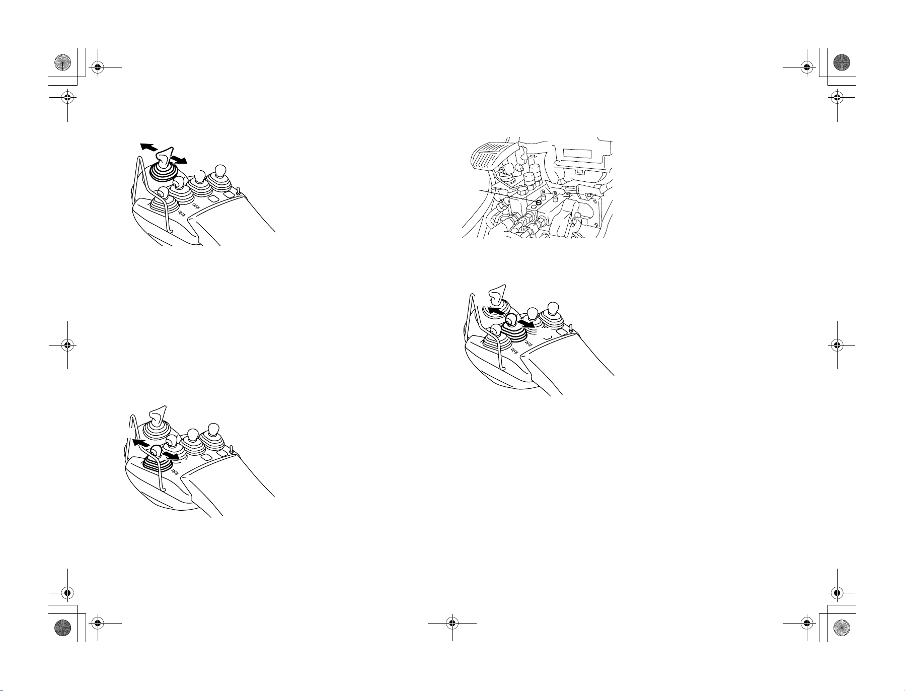
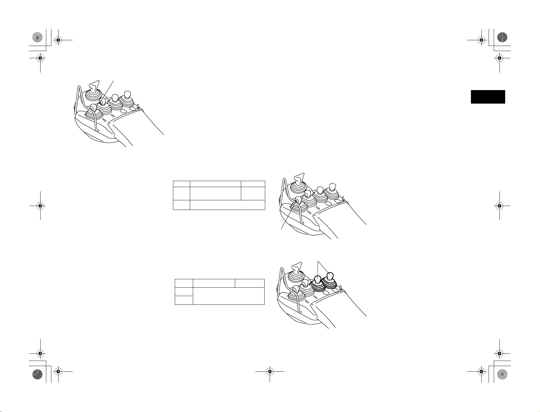
Mini lever (Option)
Control lever
Lever for shifting between forward and
reverse.
Forward.................................... Push forward
Reverse..................................... Pull backward
The speed of forward and backward traveling
can be adjusted by the extent of pressing the
accelerator pedal.
Note:
• Stop the vehicle before shifting between
forward and backward traveling.
• After the OPS System has been activated,
return the accelerator pedal and control
lever to their neutral positions and return to
the seat before recommencing operations.
• Always operate the control lever from a
properly seated position.
• Depending on the vehicle specifications,
the position of the control lever may vary.
Lift lever
Raise and lower the forks for loading.
Raise.......................................... Pull backward
Lower ......................................... Push forward
Raising speed can be adjusted by the extent of
pressing the accelerator pedal and pulling the
lift lever.
Lowering speed can be adjusted by the extent
of pushing the lift lever.
Note:
• After the OPS System has been activated,
return the accelerator pedal and all of the
levers to their neutral positions and return
to the seat before recommencing operations.
• If you return to the seat while lowering the
lift lever, the forks will not descend due to
the return to neutral function.
• Always operate the lift lever from a properly seated position.
(1)
(1) Lift lock release bolt
(1)
(1) Forward
(2) Backward
(2)
Note:
• If you use the idling lifting speed increase
function (Option), pulling the lift lever will
automatically increase the engine speed
and raise the forks at a constant speed without having to step on the accelerator pedal.
• When the ignition switch is turned to OFF,
the forks will not descend even if the lift
lever is lowered. (Key-lift interlock)
• When the forks will not lower due to system malfunction or other reasons, they can
be lowered by opening the lift lock release
bolt.
• If you lower the forks by opening the lift
lock release bolt, close and lock the bolt.
Tilt lever
Tilt the mast forward and backward.
Forward ..................................... Push forward
Backward..................................Pull backward
Forward or backward tilting speed can be
adjusted by the extent of pressing the accelerator pedal and operating the lever.
Note:
• After the OPS System has been activated,
return the accelerator pedal and all of the
levers to their neutral positions and return
to the seat before recommencing operations.
• Always operate the tilt lever from a properly seated position.
en-22
01_A5028-0E00_En.fm 23 ページ 2007年7月4日 水曜日 午後4時1分
(1)
(1) Automatic forks leveling switch
Automatic fork leveling switch
(Works same as the tilt lever knob
switch.)
While pressing the switch when the forks are
tilted forward from a backward-tilted position,
or backward from a forward-tilted position, the
forks will automatically stop at a horizontal
position. Releasing the switch will allow for
normal tilt lever operation.
Forks forward-tilt automatic leveling control
When the forks are in a backward-tilted position, operating the lever forward while
depressing the automatic fork leveling switch
will automatically stop the forks at a horizontal
position. This function is convenient when
handling loads or attaching/detaching forks.
While depressing the automatic fork leveling
switch, operating the forks forward from a
backward-tilted position:
Not loaded Loaded
High lift Forks stopped at their horizontal
position
(with mast vertically positioned)
Low lift Forks stopped at their horizontal position
(with mast vertically positioned)
Forks backward-tilt automatic leveling control
When the forks are in a forward-tilted position,
operating the lever backward while depressing
the automatic fork leveling switch will automatically stop the forks at a horizontal position. This function is convenient when using
clamp-type attachments while the mast is tilted
forward from the vertical position.
While pressing the automatic forks leveling
switch, operating the forks backward from a
forward-tilted position:
Not loaded Loaded
High lift
Forks stopped at their horizontal position
(with mast vertically positioned)
Low lift
No forward tilt
(1)
(1) Load meter switch
(1)
Active mast rear tilt speed control
When the mast is raised to a high position,
backward-tilt speed will automatically slow
down.
Load meter switch (Option)
For vehicles equipped with Multifunction display DX (Option), pressing the load meter
switch will display the weight of the load.
Note:
• Operate this function when you are not performing loading operations.
• When weighing the load, always remember
to position the load at a height of about
500mm above the ground and make the
mast perpendicular.
Attachment lever
Operates the attachment.
Attachment speed can be adjusted by the
extent of pressing the accelerator pedal and
operating the lever.
Note:
• After the OPS System has been activated,
return the accelerator pedal and all of the
levers to their neutral positions and return
to the seat position before recommencing
operations.
• Always operate the attachment lever from a
properly seated position.
en
(1) Attachment lever
en-23
01_A5028-0E00_En.fm 24 ページ 2007年7月4日 水曜日 午後4時1分
(1) Attachment lever switch
(1)
(2)
(1) Forward
(2) Backward
(1)
Attachment lever switch
(Only for 5 ways series)
This switch allows attachment lever operations
to be switched between the 3rd and 4th ways.
It is for 3rd operation when the changing-over
switch is not switched. And it switches to 5th
operation while pushing it.
CautionCaution
Operate the attachment lever switch when
attachment operations are stopped.
Joy stick (Option)
Control lever
Lever for shifting between forward and
reverse.
Forward.................................... Push forward
Reverse..................................... Pull backward
The speed of forward and backward traveling
can be adjusted by the extent of pressing the
accelerator pedal.
Note:
• Stop the vehicle before shifting between
forward and backward traveling.
• After the OPS System has been activated,
return the accelerator pedal and control
lever to their neutral positions and return to
the seat before recommencing operations.
• Always operate the control lever from a
properly seated position.
• Depending on the vehicle specifications,
the position of the control lever may vary.
(3)
(2)
(1) Raising
(2) Lowering
(3) Forward-tilt
(4) Backward-tilt
(1)
(1) Lift lock release bolt
(1)
(4)
Lift tilt lever
Operation to the left and right controls lift, and
forward and backward operation controls tilt.
Raising ...............Operate the lever to the right
Lowering.............. Operate the lever to the left
Forward-tilt ............Operate the lever forward
Backward-tilt.......Operate the lever backward
Raising speed and forward and backward-tilt
speed can be adjusted by the extent of pressing
down on the accelerator pedal and operating
the lever.
Lowering speed can be adjusted by operating
the lever.
Note:
• Using the idling lifting speed increase function (Option), when the lift tilt lever is
raised, the engine’s speed is automatically
increased without having to press the accelerator pedal, allowing the forks to be raised
at a constant speed.
• After the OPS System has been activated,
return the accelerator pedal and all of the
levers to their neutral positions and return
to the seat before recommencing operations.
• If you return to seated position while lowering the lift lever, the lift will not descend
due to the return to neutral warning function.
• Always operate the load handling lever
from a properly seated position.
• If you use the idling lifting speed increase
function (Option), pulling the lift lever will
automatically increase the engine speed
and raise the forks at a constant speed without having to step on the accelerator pedal.
• When the ignition switch is turned to OFF,
the forks will not descend even if the lift
lever is lowered. (Key-lift interlock)
• When the forks will not lower due to system malfunction or other reasons, they can
be lowered by opening the lift lock release
bolt.
• If you lower the forks by opening the lift
lock release bolt, close and lock the bolt.
en-24
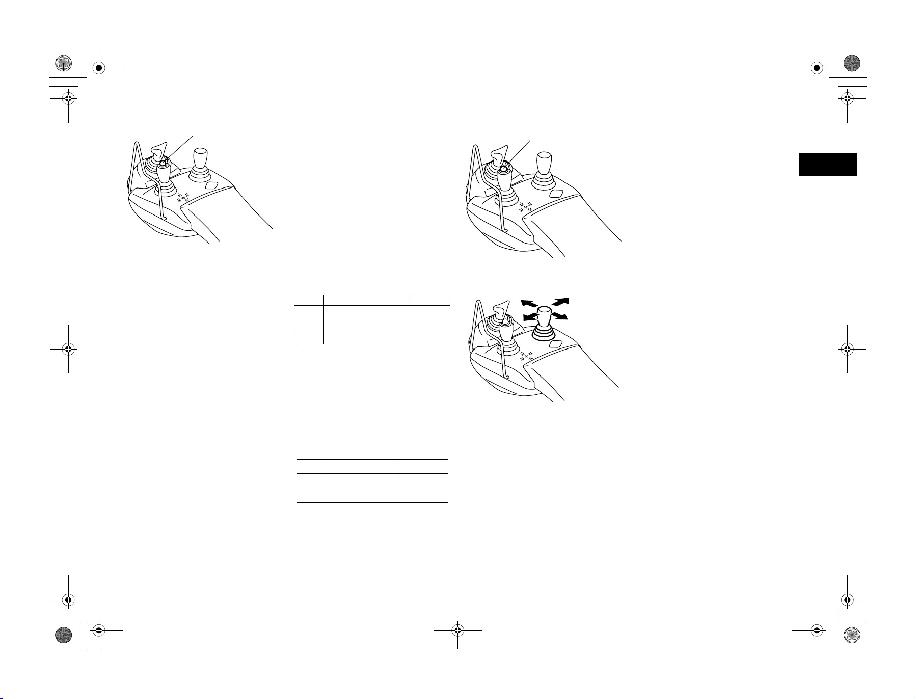
01_A5028-0E00_En.fm 25 ページ 2007年7月4日 水曜日 午後4時1分
(1)
(1) Automatic forks leveling switch
Forks automatic leveling switch
While pressing the switch and the forks are
operated forward from a backward-tilted position, or backward from a forward-tilted position, the forks will automatically stop at a
horizontal position. Releasing the switch will
allow for normal tilt lever operation.
Forks forward-tilt automatic leveling control
When the forks are in a backward-tilted position, operating the lever forward while pressing the automatic forks leveling switch will
automatically stop the forks at a horizontal
position. This function is convenient when
handling loads or attaching/detaching forks.
While pressing the automatic forks leveling
switch, operating the forks forward from a
backward-tilted position:
Not loaded Loaded
High lift Forks stopped at their horizontal
position
(with mast vertically positioned)
Low lift Forks stopped at their horizontal position
(with mast vertically positioned)
Forks backward-tilt automatic leveling control
When the forks are in a forward-tilted position,
operating the lever backward while depressing
the automatic fork leveling switch will automatically stop the forks at a horizontal position. This function is convenient when using
clamp-type attachments while the mast is tilted
forward from the vertical position.
No forward tilt
(1)
(1) Automatic forks leveling switch
Load meter display
In the case of vehicles with multifunction display DX (Option), pressing the fork automatic
leveling switch will display the weight of the
load being handled.
Note:
• The load meter switch and fork automatic
leveling control switch functions are combined.
• Operate this function when loading is not
being conducted.
• When weighing the load, always remember
to position the load at a height of about
500mm above the ground and make the
mast perpendicular.
Attachment lever
Operates attachment. Attachment speed can be
adjusted by the extent of pressing the accelerator pedal and operating the lever.
Note:
• After the OPS System has been activated,
return the accelerator pedal and all of the
levers to their neutral positions and return
to the seat before recommencing operations.
• Operate the attachment lever after you are
seated properly in the vehicle.
en
While pressing the automatic forks leveling
switch, operating the forks backward from a
forward-tilted position:
Not loaded Loaded
High lift
Forks stopped at their horizontal position
(with mast vertically positioned)
Low lift
Active mast rear tilt speed control
When the mast is raised to a high position,
backward-tilt speed will automatically slow
down.
en-25
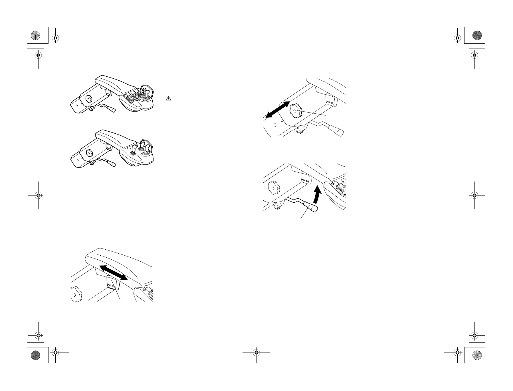
01_A5028-0E00_En.fm 26 ページ 2007年7月4日 水曜日 午後4時1分
Mini lever models
Joy stick models
Arm rest
(Mini lever and Joy stick models)
Before starting up the engine, adjust the arm
rest to set the optimum driving position.
CautionCaution
• After you have finished adjusting the
arm rest forward-backward position,
height and tilt, confirm that the knob
and the lever have been secured in place.
A loose knob or lever may cause an accident.
• Do not adjust the position of the arm rest
while operating the vehicle.
• To operate the vehicle in safely, lock the
arm rest securely. Before operating the
vehicle, always confirm that the lever for
turning and securing the arm rest is
locked.
Adjusting the backward-and-forward position
Pull up and loosen the forward-backward position adjusting knob. Adjust the arm rest forward-backward position. Then press the knob,
securing it in place.
(1) Height adjustment knob
(1)
(1) Tilt adjustment lever
(1)
Adjusting the height position
Turn the knob counterlockwise to release the
lock.Then, move the arm rest up-and-down to
place it to an appropriate position. Turn knob
clockwise to lock.
Adjusting the tilt position
Lift and loosen the lever for turning and securing the arm rest. Adjust the tilt of the arm
rest.Then push the lever down,securing it in
place.This lever is used in order to turn the arm
rest when you open and close the engine hood.
(1)
(1) Backward-and-forward position adjust-
ment knob
en-26
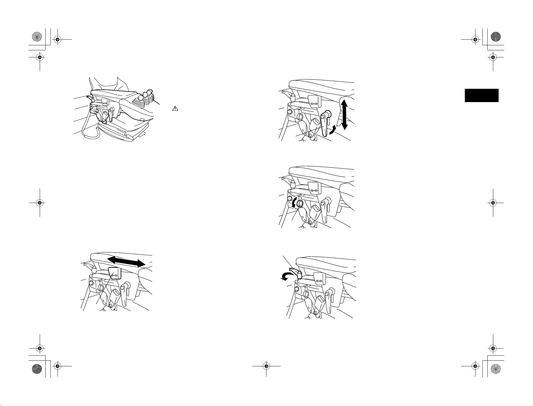
01_A5028-0E00_En.fm 27 ページ 2007年7月4日 水曜日 午後4時1分
Arm rest
(Mini lever and Joy stick with Premium cabin models)
Before starting up the engine, adjust the arm
rest to set the optimum driving position.
CautionCaution
• After you have finished adjusting the
arm rest forward-backward position,
height and tilt, confirm that the knob
and the lever have been secured in place.
a loose knob or lever may cause an accident.
• When you adjust the arm rest position,
confirm by tightening the knob and lock
the arm rest securely. A loose knob may
cause an operational error.
• Do not adjust the position of the arm rest
while operating the vehicle.
• To operate the vehicle in safely, lock the
arm rest securely. Before operating the
vehicle, always confirm that the lever for
turning and securing the arm rest is
locked.
Adjusting the backward-and-forward position
Pull up and loosen the forward-backward position adjusting knob. Adjust the arm rest forward-backward position. Then press the knob,
securing it in place.
(1)
(1) Height adjustment lever
(1)
(1) Tilt adjustment knob
(1)
Adjusting the height position
Turn the lever counterclockwise to release the
lock. Then, move the arm rest up-and-down to
place it to an appropriate position. Turn lever
clockwise to lock.
Adjusting the tilt position
Lift and loosen the tilt adjustment knob
counter clockwise to adjust the tilt of the arm
rest. This lever is also used in order to spring
up the arm rest.
Adjusting the turning position
Lift and loosen the turning lever counter clockwise to turn the arm rest from side to side.
This lever is used in order to turn the arm rest
when you open and close the engine hood.
en
(1)
(1) Backward-and-forward position adjust-
ment knob
(1) Turning lever
en-27
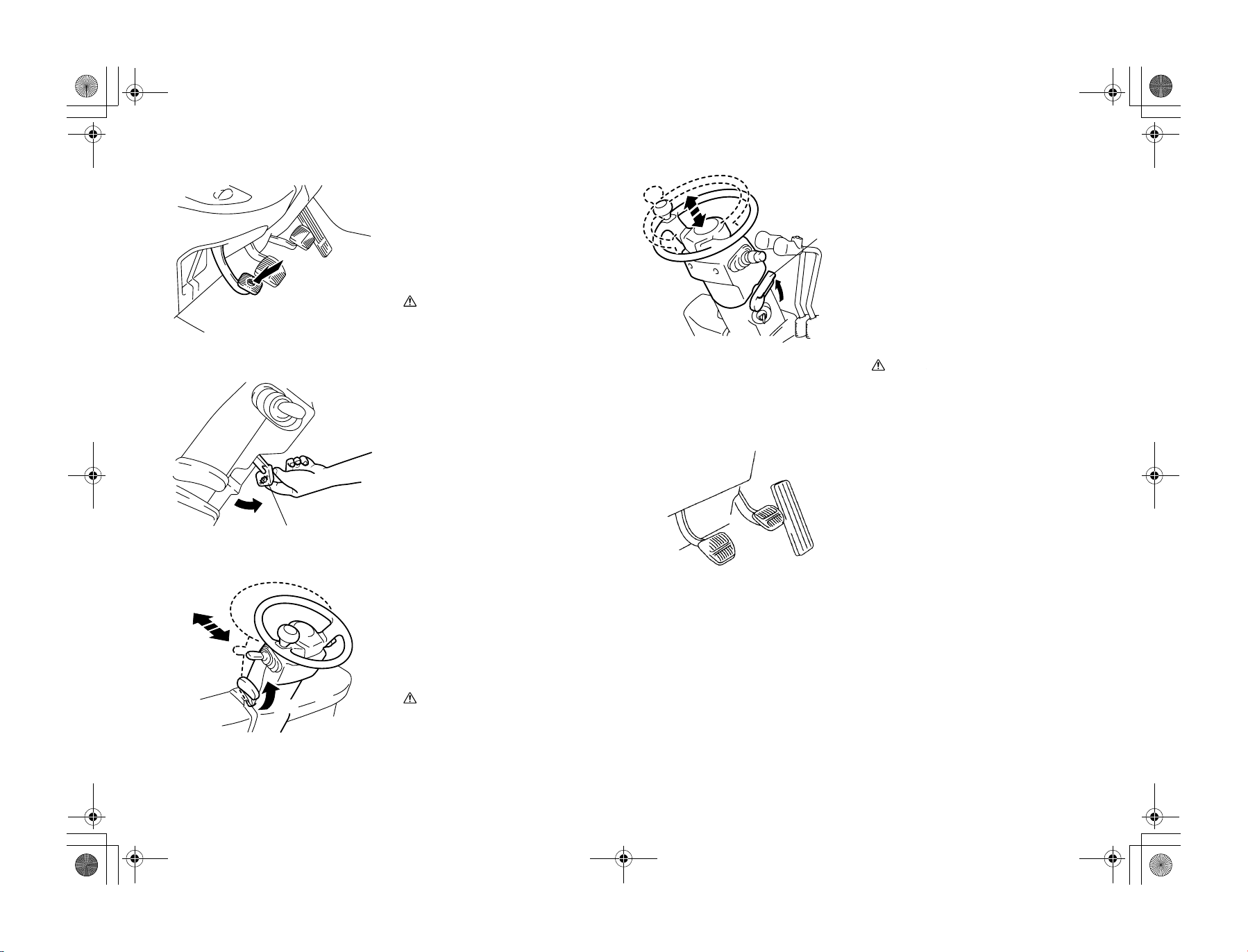
01_A5028-0E00_En.fm 28 ページ 2007年7月4日 水曜日 午後4時1分
(1) Press down
(2) Release lever
(2)
(1)
Parking brake pedal
Use the parking brake pedal when parking or
stopping.
1. When engaging the parking brake, while
stepping on the brake pedal, fully press
down on the parking brake pedal.
2. To disengage the parking brake pedal,
while stepping on the brake pedal, pull
the release lever toward you.
Warni ng
• Before operating the parking brake
pedal, step on the brake pedal and
always confirm that the vehicle has come
to a stop.
• When parking on a slope, apply wheel
chocks to the wheels.
• Traveling without releasing the brake
will decrease the brake performance.
Tilt steering adjustment
1. The steering wheel position may be
adjusted back and forth while the tilt
steering adjust lever up.
2. Lowering the lever at the proper position
fixes the steering wheel at that position.
3. After the adjustment, try to move the
steering wheel back and forth to see that
it is fixed.
(1) Height adjustment lever
(1)
Telescopic steering (Option)
Use the telescopic steering to adjust the height
of the steering wheel.
1. Pull up the height adjustment lever
2. Hold the steering wheel with both hands,
and adjust the height.
3. Hold the height adjustment lever down at
the proper position, and lock the steering
wheel securely. The steering wheel will
be locked.
4. After you have finished adjusting the
steering wheel, move the wheel up and
down to confirm that it has been locked
securely.
CautionCaution
The steering wheel position must be
adjusted before starting the vehicle.
Adjustment during traveling must be
avoided.
Pedals
From the right: accelerator pedal, brake pedal
and inching pedal.
Note:
Accelerator pedal stays neutral even when control lever is shifted to forward-reverse,due to
accelerator switch.
The vehicle will move only when accelerator
pedal is depressed.
(1) Raised
en-28
(1)
CautionCaution
The steering wheel position must be
adjusted before starting the vehicle.
Adjustment during traveling must be
avoided.
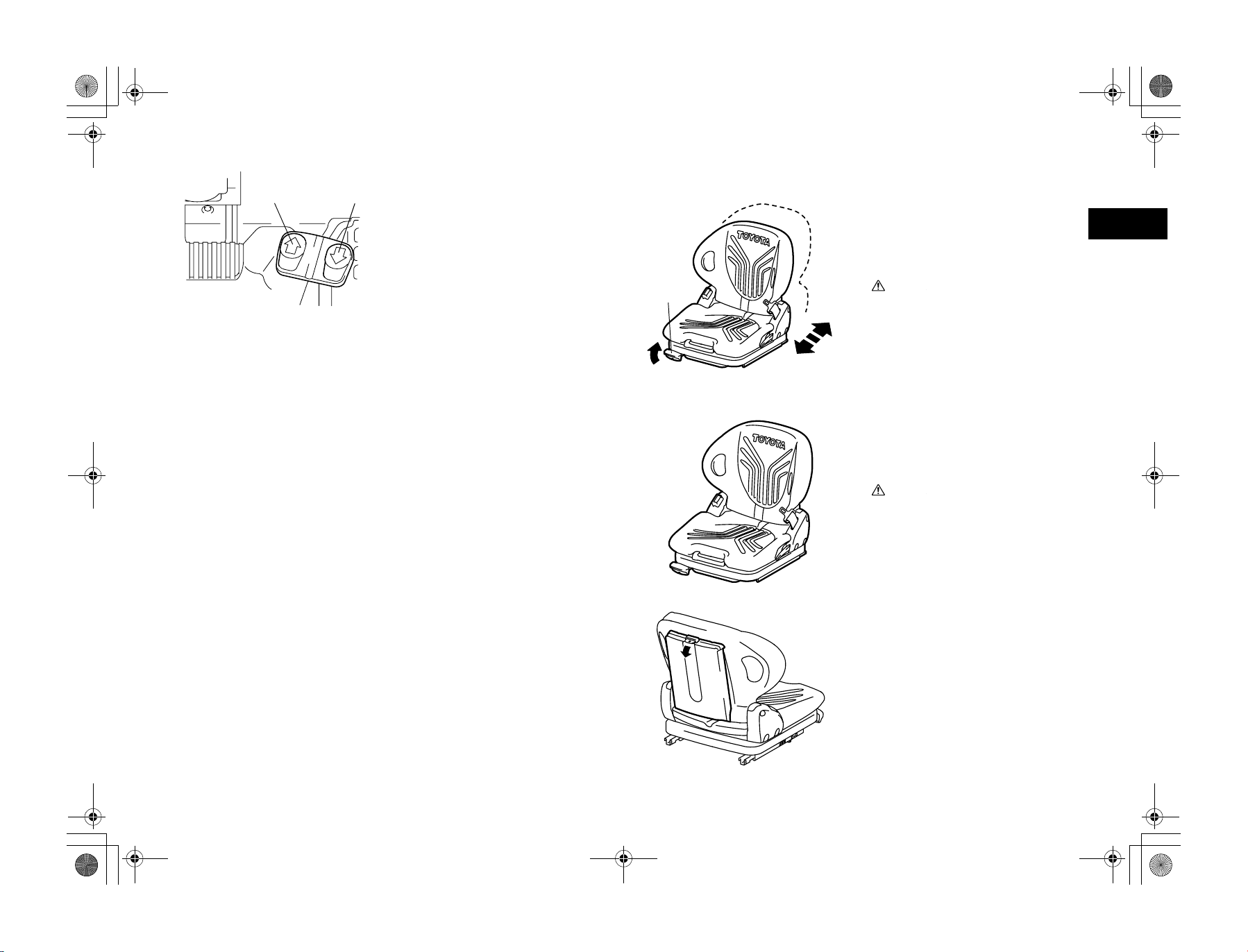
01_A5028-0E00_En.fm 29 ページ 2007年7月4日 水曜日 午後4時1分
(1) Forward
(2) Backward
(1) (2)
D2 pedal (Option)
These pedals are used for foot pedal for travel
shifting, and acceleration.
Forward................... Step on the left side
Backward................. Step on the right side
Each pedal functions as accelerator pedal.
Speed is adjustable by depth of depression.
Note:
• When OPS System has been activated, it
can be released by sitting on the operator's
seat correctly and stepping D2 pedal or by
depressing parking brake pedal once and
then releasing it.
• D2 pedal models can only start an engine
when the parking brake is on.
of the pedal.
of the pedal.
BODY COMPONENTS
(1)
(1) Adjustment lever
Operator’s seat
The operator’s seat and seat belt are provided
for your safety.
The seat can be moved back and forth for position adjustment while the adjust lever is pulled
upward.
CautionCaution
• Due to the seat switch, the forklift cannot
be driven and the forks cannot be raised
or lowered unless the operator is sitting
on the seat. Therefore, please sit on the
seat before attempting to operate the
forklift. Moreover, do not operate it with
an object placed on the seat.
• Do not turn on the seat switch by any
method other than sitting on the seat.
Operator Restraint System
A specially designed operator’s seat and seat
belt are provided for your safety. Get in the
habit of using the seat belt whenever you sit on
the vehicles.
CautionCaution
Always adjust your seating position before
driving the vehicle.
en
An operator’s manual and operator’s manual
for safety operation are located on the rear side
of the seat. If your vehicle dose not have an
operator’s manual and operator’s manual for
safety operation, please contact (your authorized Toyota dealer) to obtain copies for your
vehicle.
en-29
 Loading...