


Toyopuc PC3/PC2 Ethernet Driver
© 2016 PTC Inc. All Rights Reserved.

Toyopuc PC3/PC2 Ethernet Driver
Table of Contents
2
Toyopuc PC3/PC2 Ethernet Driver
Table of Contents
Toyopuc PC3/PC2 Ethernet Driver
Overview
Setup
Channel Properties - General 6
Channel Properties - Ethernet Communications 7
Channel Properties - Write Optimizations 8
Channel Properties - Advanced 9
Device Properties - General 9
Device Properties - Scan Mode 11
Device Properties - Timing 12
Device Properties - Communications Parameters 13
Device Properties - Redundancy 13
Diagnostics Tags
Multi-Point Read Support
Data Type Description
1
2
4
4
5
14
15
19
Address Descriptions
PC2/PC2 Interchange Mode Address Descriptions
PC3 Address Descriptions
PC10G Address Descriptions
Error Descriptions
Address Validation
Missing address. 31
Device address <address> contains a syntax error. 31
Address <address> is out of range for the specified device or register 31
Data Type <type> is not valid for device address <address>. 32
Device address <address> is read only. 32
Array size is out of range for address <address>. 32
Array support is not available for the specified address: <address>. 32
Device Status Messages
Device <device name> is not responding. 33
Unable to write to <address> on device <device name>. 33
Device Error Codes
20
20
22
26
31
31
33
34
Error Response Data: Error Code Table 34
Appendix: Configuring Modules
www. kepware.com
36

3
Toyopuc PC3/PC2 Ethernet Driver
Configuring the PC10G-CPU for Ethernet Communications
Configuring the FL/ET-T-V2 Ethernet Module
Configuration Ladder for EN-I/F Ethernet Module
Index
36
41
46
48
www. kepware.com

Toyopuc PC3/PC2 Ethernet Driver
Toyopuc PC3/PC2 Ethernet Driver
Help version 1.042
CONTENTS
Overview
What is the Toyopuc PC3/PC2 Ethernet Driver?
Device Setup
How do I configure a device for use with this driver?
Data Types Description
What data types does this driver support?
Address Descriptions
How do I address a data location on a Toyopuc PC3/PC2 Ethernet device?
Error Descriptions
What error messages does the Toyopuc PC3/PC2 Ethernet Driver produce?
4
Overview
The Toyopuc PC3/PC2 Ethernet Driver provides a reliable way to connect Toyopuc PC3/PC2 Ethernet devices
to OPC client applications; including HMI, SCADA, Historian, MES, ERP, and countless custom applications. It
is intended for use with Toyopuc PC3, PC2 and PC10G series PLCs using the Ethernet communications
interface. The Toyopuc PC3/PC2 Ethernet Driver supports extensive diagnostics tags and the Toyopuc
PC3/PC2 multi-point read features. For more information, refer to Diagnostics Tags and Multi-Point Read
Support .
www. kepware.com

5
Toyopuc PC3/PC2 Ethernet Driver
Setup
Supported Devices
Toyopuc PC3, PC2 and PC10G series
The PC2 model selection can be used with PC3 > PLCs operating in the PC2 Interchange mode.
Note: This driver is limited to 1024 devices.
Communication Protocol
Toyopuc PC3/PC2 Ethernet Computer Link Protocol
Connection Timeout
This property specifies the time that the driver will wait for a connection to be made with a device.
Depending on network load, the connect time may vary with each connection attempt. The default setting is
5 seconds. The valid range is 1 to 30 seconds.
Note: Making a connection with a device can be very time consuming. When connecting with multiple
devices located at different IP addresses or port numbers, define an additional Toyopuc Ethernet channel in
the OPC Server project for this unique device. Connecting to multiple devices using the Relay Command
through a single IP and port number will not cause a new connection to be opened and will not incur a
connection delay.
Port Number
This property specifies the port number that will be used to connect to the Toyopuc PLC. The Toyopuc EN-I/F
Ethernet PC3/PC2 module supports eight ports for communications. Each port must be dedicated to a single
connection. When specifying a port number, ensure that no other Ethernet node will attempt to use this port
number on the target Toyopuc PLC. The same port number can be used when communicating with multiple
Toyopuc PLCs.
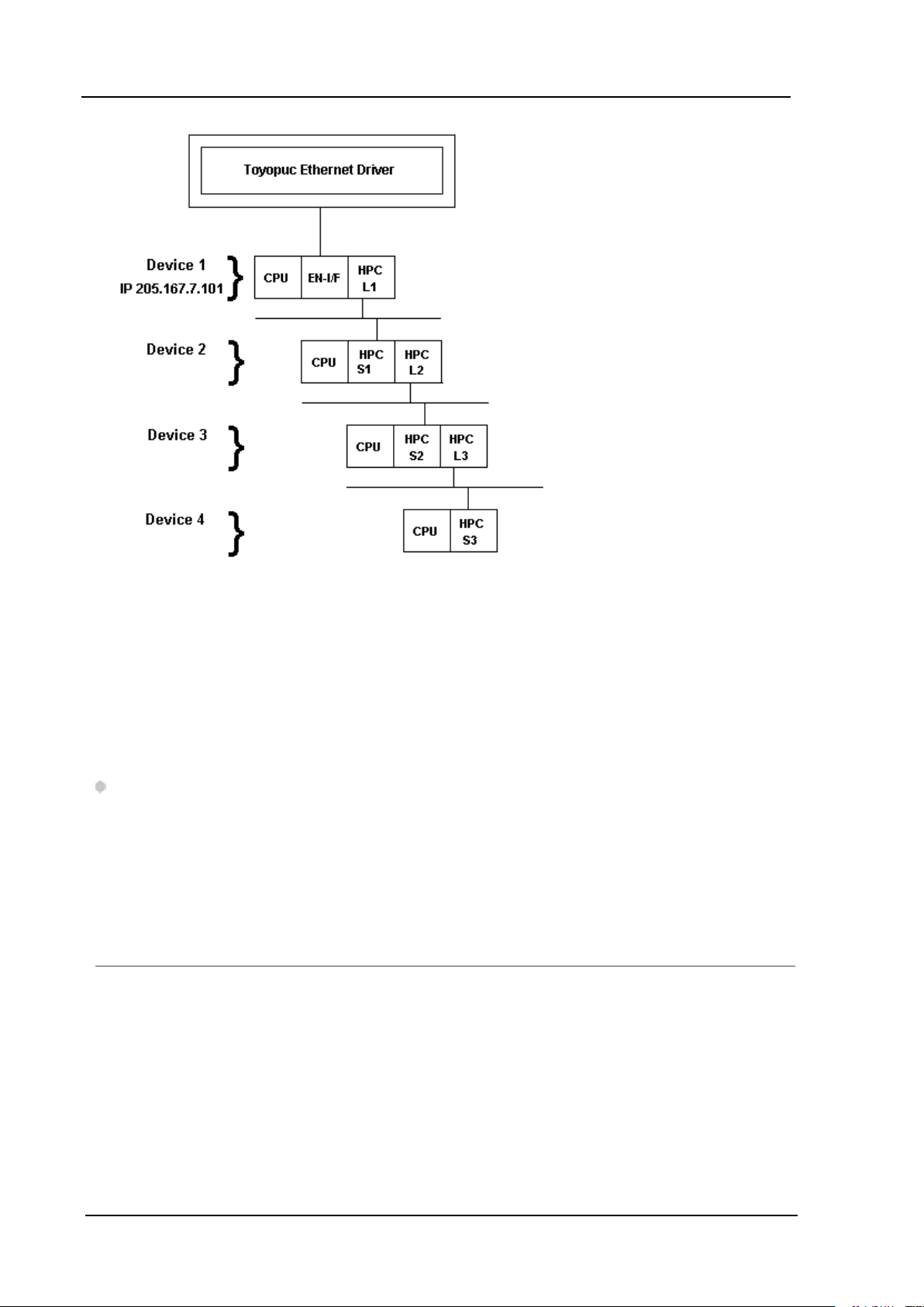
Device IDs
The Device ID, specified as YYY.YYY.YYY.YYY[P1,L1, S1, L2, S2, P3, L3, S3], is used to specify the Device IP
address along with Relay Command Link/Exchange information on the Ethernet network. YYY designates the
Device IP address: each YYY byte should be in the range of 0 to 255.
Note: A request can be relayed through one device to another device configured with the same link
module, such as HPC-Link or FL-net. This relay connection is established by appending a link/exchange path
to the device IP address. The following image illustrates the use of the routing path between HPC-linked
devices:
www. kepware.com
Toyopuc PC3/PC2 Ethernet Driver
6
A routing command can only be issued through a maximum of four devices. Routing allows the Ethernet
driver to request data from non-Ethernet devices. To request data from Device 3, the driver can route a
command through Device 1 onto Device 2 then to Device 3.
Examples
1. Defining a Device ID to request data from Device 1. Device ID: 205.167.7.101.
2. Defining a Device ID to request data from Device 3. Device ID: 205.167.7.101[L1,S1,L2,S2].
Note: Lx and Sx represent the Link/Station numbers assigned to a device. . Consult the Toyopuc PC2 EN-I/F
manual, HPC Link manual, or FL/ET-T-V2H manual for more information on link/station numbers.The L and S
must be included as part of the Relay routing information when specifying a Device ID. The Px represents the
program number for PC3J systems. The Px value should precede the link variable on each layer of the route.
Example
Device ID: 205.167.7.101[P2,L1,S1,P1,L2,S2].
Channel Properties - General
This server supports the use of simultaneous multiple communications drivers. Each protocol or driver used
in a server project is called a channel. A server project may consist of many channels with the same
communications driver or with unique communications drivers. A channel acts as the basic building block of
an OPC link. This group is used to specify general channel properties, such as the identification attributes
and operating mode.
www. kepware.com
7
Toyopuc PC3/PC2 Ethernet Driver
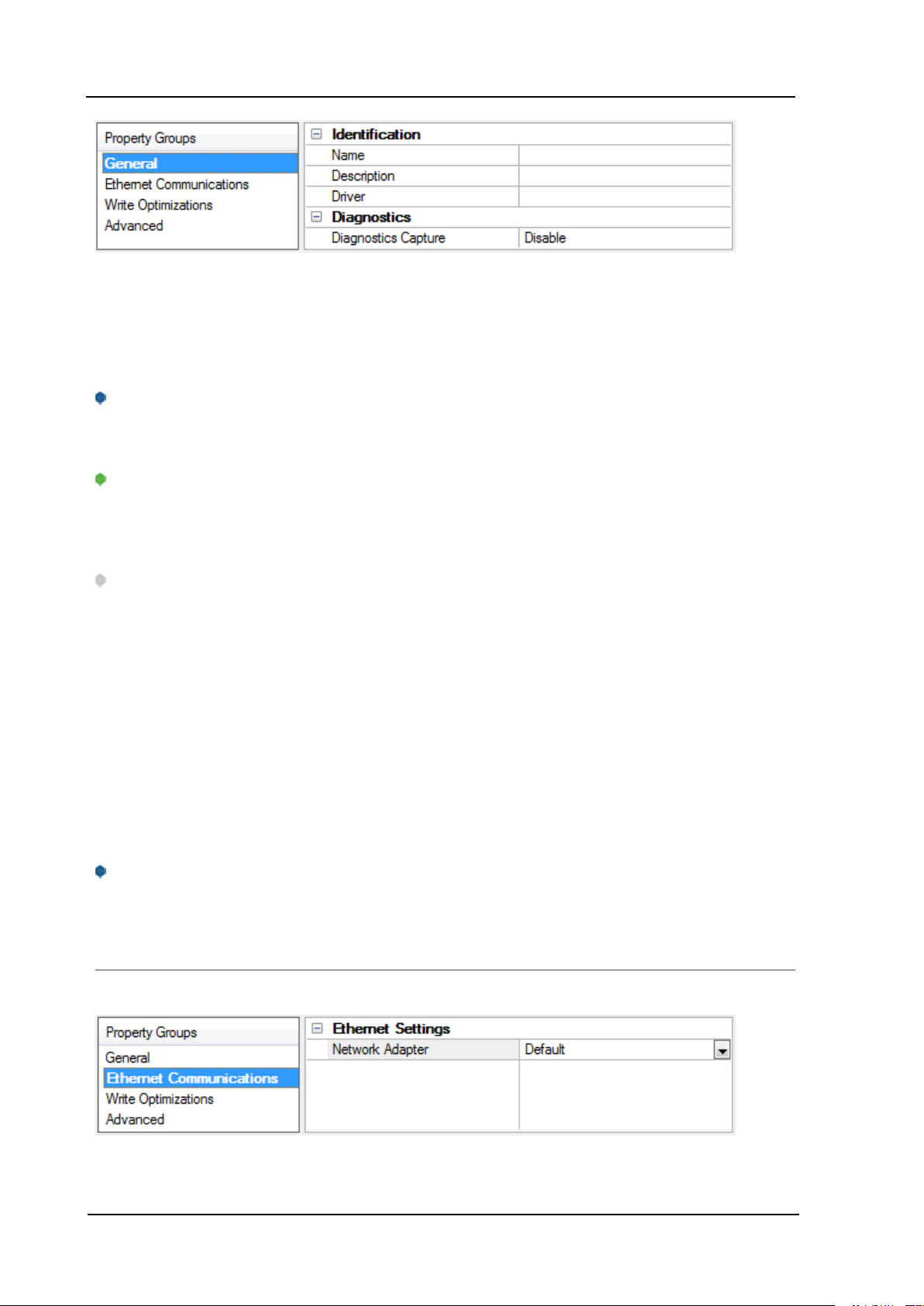
Identification
Name:User-defined identity of this channel. In each server project, each channel name must be unique.
Although names can be up to 256 characters, some client applications have a limited display window when
browsing the OPCserver's tag space. The channel name is part of the OPC browser information.
For information on reserved characters, refer to "How To... Properly Name a Channel, Device, Tag, and Tag
Group" in the server help.
Description: User-defined information about this channel.
Many of these properties, including Description, have an associated system tag.
Driver:Selected protocol / driver for this channel. This property specifies the device driver that was selected
during channel creation. It is a disabled setting in the channel properties.
Note: With the server's online full-time operation, these properties can be changed at any time. This
includes changing the channel name to prevent clients from registering data with the server. If a client has
already acquired an item from the server before the channel name is changed, the items are unaffected. If,
after the channel name has been changed, the client application releases the item and attempts to reacquire using the old channel name, the item is not accepted. With this in mind, changes to the properties
should not be made once a large client application has been developed. Utilize the User Manager to prevent
operators from changing properties and restrict access rights to server features.
Diagnostics
Diagnostics Capture: When enabled, this option makes the channel's diagnostic information available to
OPC applications. Because the server's diagnostic features require a minimal amount of overhead
processing, it is recommended that they be utilized when needed and disabled when not. The default is
disabled.
For more information, refer to "Communication Diagnostics" in the server help.
Not all drivers support diagnostics. To determine whether diagnostics are available for a particular driver, open
the driver information and locate the "Supports device level diagnostics" statement.
Channel Properties - Ethernet Communications
Ethernet Communication can be used to communicate with devices.
Ethernet Settings
www. kepware.com
Toyopuc PC3/PC2 Ethernet Driver
Network Adapter:Specify the network adapter to bind. When Default is selected, the operating system
selects the default adapter.
Channel Properties - Write Optimizations
As with any OPC server, writing data to the device may be the application's most important aspect. The
server intends to ensure that the data written from the client application gets to the device on time. Given
this goal, the server provides optimization properties that can be used to meet specific needs or improve
application responsiveness.
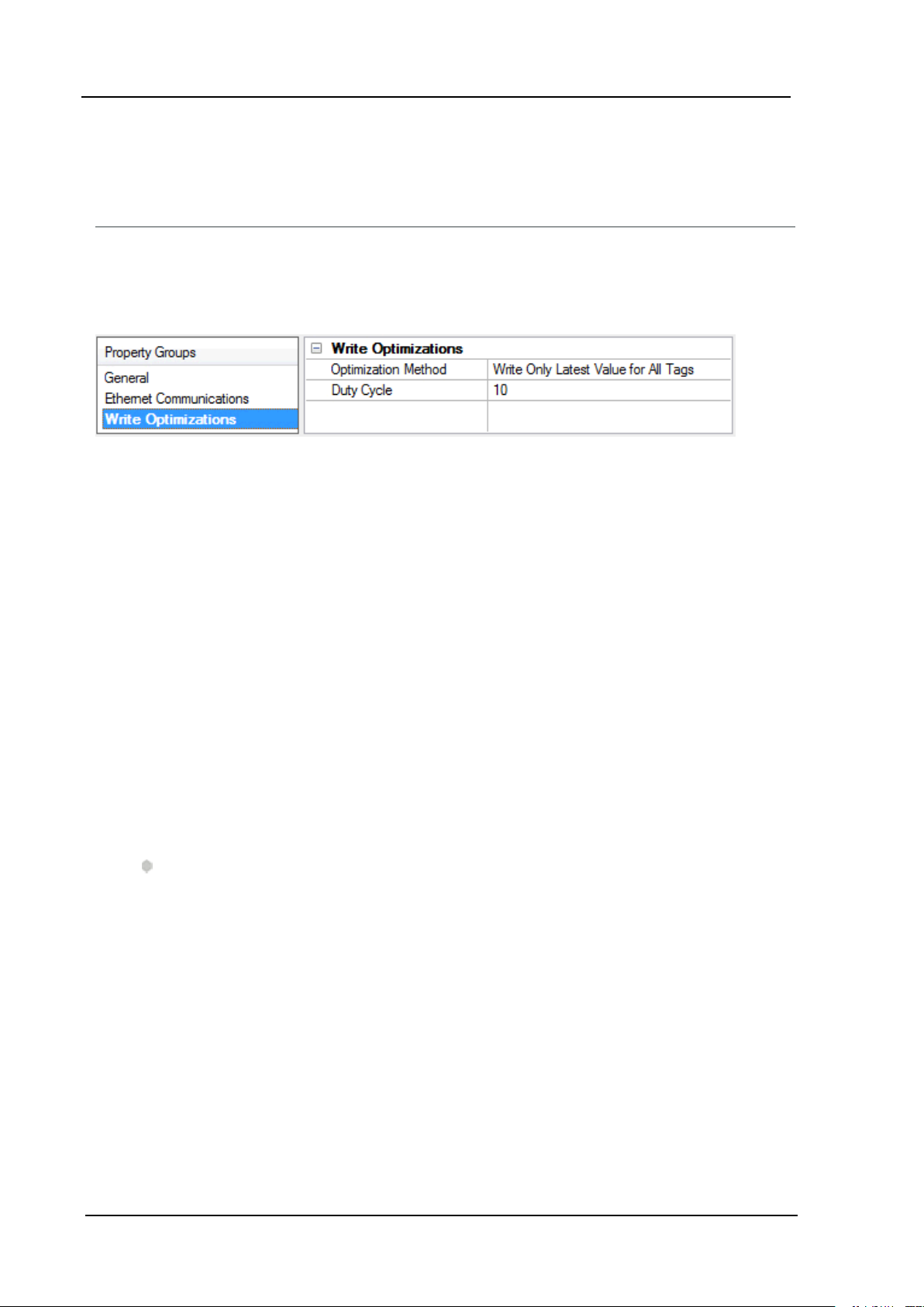
Write Optimizations
OptimizationMethod: controls how write data is passed to the underlying communications driver. The
options are:
8
l Write All Values for All Tags:This option forces the server to attempt to write every value to the
controller. In this mode, the server continues to gather write requests and add them to the server's
internal write queue. The server processes the write queue and attempts to empty it by writing data
to the device as quickly as possible. This mode ensures that everything written from the client
applications is sent to the target device. This mode should be selected if the write operation order or
the write item's content must uniquely be seen at the target device.
l Write Only Latest Value for Non-Boolean Tags: Many consecutive writes to the same value can
accumulate in the write queue due to the time required to actually send the data to the device. If the
server updates a write value that has already been placed in the write queue, far fewer writes are
needed to reach the same final output value. In this way, no extra writes accumulate in the server's
queue. When the user stops moving the slide switch, the value in the device is at the correct value at
virtually the same time. As the mode states, any value that is not a Boolean value is updated in the
server's internal write queue and sent to the device at the next possible opportunity. This can greatly
improve the application performance.
Note: This option does not attempt to optimize writes to Boolean values. It allows users to
optimize the operation of HMI data without causing problems with Boolean operations, such as a
momentary push button.
l Write Only Latest Value for All Tags:This option takes the theory behind the second optimization
mode and applies it to all tags. It is especially useful if the application only needs to send the latest
value to the device. This mode optimizes all writes by updating the tags currently in the write queue
before they are sent. This is the default mode.
Duty Cycle: is used to control the ratio of write to read operations. The ratio is always based on one read for
every one to ten writes. The duty cycle is set to ten by default, meaning that ten writes occur for each read
operation. Although the application is performing a large number of continuous writes, it must be ensured
that read data is still given time to process. A setting of one results in one read operation for every write
operation. If there are no write operations to perform, reads are processed continuously. This allows
optimization for applications with continuous writes versus a more balanced back and forth data flow.
www. kepware.com
9
Toyopuc PC3/PC2 Ethernet Driver
Note: It is recommended that the application be characterized for compatibility with the write
optimization enhancements before being used in a production environment.
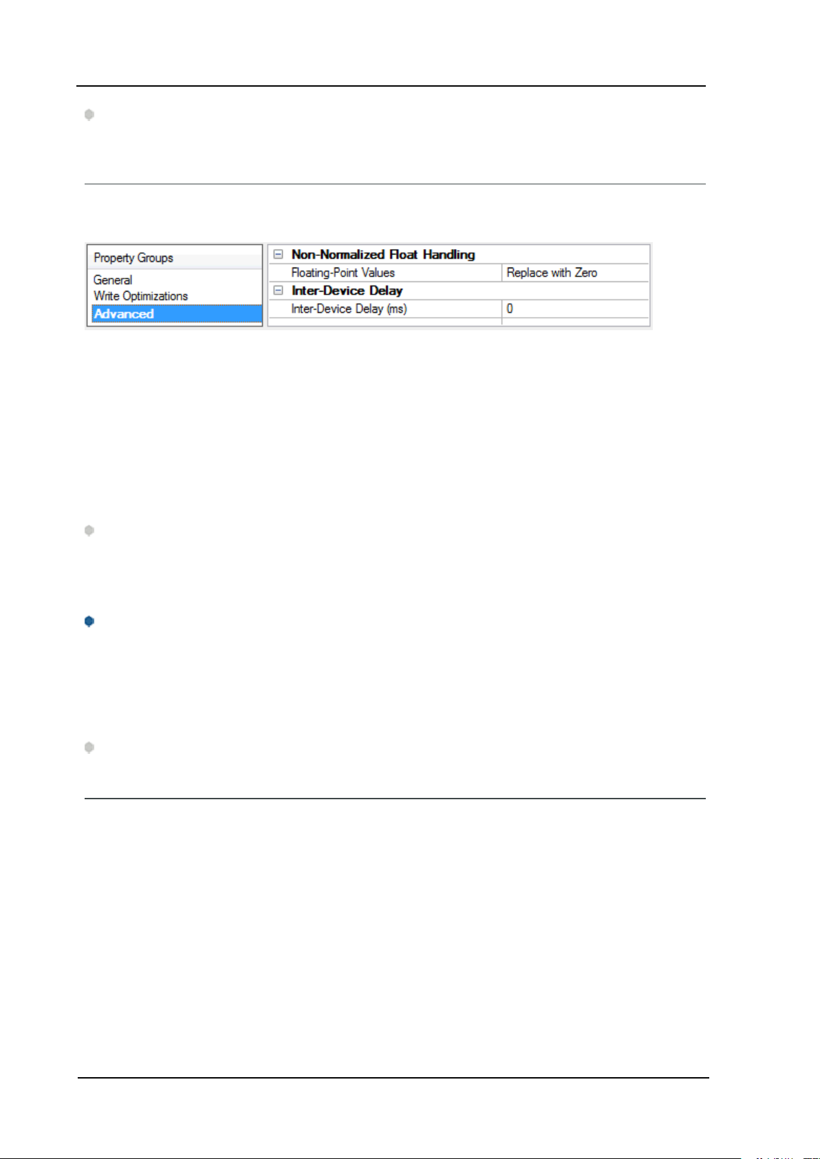
Channel Properties - Advanced
This group is used to specify advanced channel properties. Not all drivers support all properties; so the
Advanced group does not appear for those devices.
Non-Normalized Float Handling: Non-normalized float handling allows users to specify how a driver
handles non-normalized IEEE-754 floating point data. A non-normalized value is defined as Infinity, Not-aNumber (NaN), or as a Denormalized Number. The default is Replace with Zero. Drivers that have native
float handling may default to Unmodified. Descriptions of the options are as follows:
l Replace with Zero:This option allows a driver to replace non-normalized IEEE-754 floating point
values with zero before being transferred to clients.
l Unmodified:This option allows a driver to transfer IEEE-754 denormalized, normalized, non-
number, and infinity values to clients without any conversion or changes.
Note:This property is disabled if the driver does not support floating point values or if it only supports the
option that is displayed. According to the channel's float normalization setting, only real-time driver tags
(such as values and arrays) are subject to float normalization. For example, EFM data is not affected by this
setting.lin
For more information on the floating point values, refer to "How To ... Work with Non-Normalized Floating
Point Values" in the server help.
Inter-Device Delay: Specify the amount of time the communications channel waits to send new requests to
the next device after data is received from the current device on the same channel. Zero (0) disables the
delay.
Note:This property is not available for all drivers, models, and dependent settings.
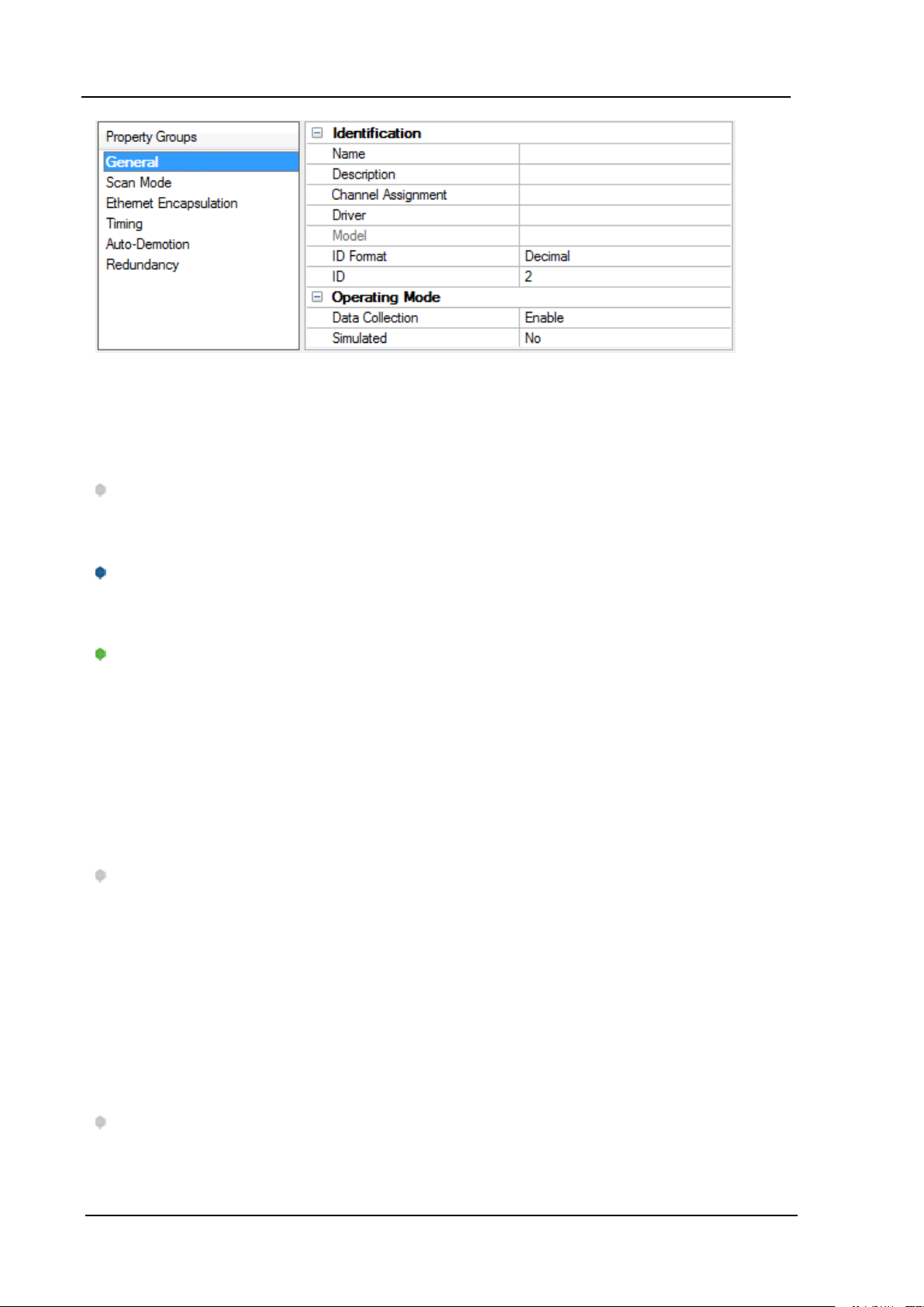
Device Properties - General
A device represents a single target on a communications channel. If the driver supports multiple controllers,
users must enter a device ID for each controller.
www. kepware.com
Toyopuc PC3/PC2 Ethernet Driver
Identification
Name:This property specifies the name of the device. It is a logical user-defined name that can be up to
256 characters long, and may be used on multiple channels.
Note: Although descriptive names are generally a good idea, some OPC client applications may have a
limited display window when browsing the OPC server's tag space. The device name and channel name
become part of the browse tree information as well. Within an OPC client, the combination of channel name
and device name would appear as "ChannelName.DeviceName".
For more information, refer to "How To... Properly Name a Channel, Device, Tag, and Tag Group" in server
help.
10
Description: User-defined information about this device.
Many of these properties, including Description, have an associated system tag.
Channel Assignment:User-defined name of the channel to which this device currently belongs.
Driver:Selected protocol driver for this device.
Model:This property specifies the specific type of device that is associated with this ID. The contents of the
drop-down menu depends on the type of communications driver being used. Models that are not supported
by a driver are disabled. If the communications driver supports multiple device models, the model selection
can only be changed when there are no client applications connected to the device.
Note:If the communication driver supports multiple models, users should try to match the model
selection to the physical device. If the device is not represented in the drop-down menu, select a model that
conforms closest to the target device. Some drivers support a model selection called "Open," which allows
users to communicate without knowing the specific details of the target device. For more information, refer
to the driver help documentation.
ID:This property specifies the device's driver-specific station or node. The type of ID entered depends on
the communications driver being used. For many communication drivers, the ID is a numeric value. Drivers
that support a Numeric ID provide users with the option to enter a numeric value whose format can be
changed to suit the needs of the application or the characteristics of the selected communications driver.
The ID format can be Decimal, Octal, and Hexadecimal.
Note: If the driver is Ethernet-based or supports an unconventional station or node name, the device's
TCP/IP address may be used as the device ID. TCP/IP addresses consist of four values that are separated by
periods, with each value in the range of 0 to 255. Some device IDs are string based. There may be additional
www. kepware.com
11
Toyopuc PC3/PC2 Ethernet Driver
properties to configure within the ID field, depending on the driver. For more information, refer to the
driver's help documentation.
Operating Mode
Data Collection:This property controls the device's active state. Although device communications are
enabled by default, this property can be used to disable a physical device. Communications are not
attempted when a device is disabled. From a client standpoint, the data is marked as invalid and write
operations are not accepted. This property can be changed at any time through this property or the device
system tags.
Simulated:This option places the device into Simulation Mode. In this mode, the driver does not attempt to
communicate with the physical device, but the server continues to return valid OPC data. Simulated stops
physical communications with the device, but allows OPC data to be returned to the OPC client as valid data.
While in Simulation Mode, the server treats all device data as reflective: whatever is written to the simulated
device is read back and each OPC item is treated individually. The item's memory map is based on the group
Update Rate. The data is not saved if the server removes the item (such as when the server is reinitialized).
The default is No.
Notes:
1. This System tag (_Simulated) is read only and cannot be written to for runtime protection. The System
tag allows this property to be monitored from the client.
2. In Simulation mode, the item's memory map is based on client update rate(s) (Group Update Rate for
OPC clients or Scan Rate for native and DDE interfaces). This means that two clients that reference
the same item with different update rates return different data.
Simulation Mode is for test and simulation purposes only. It should never be used in a production
environment.
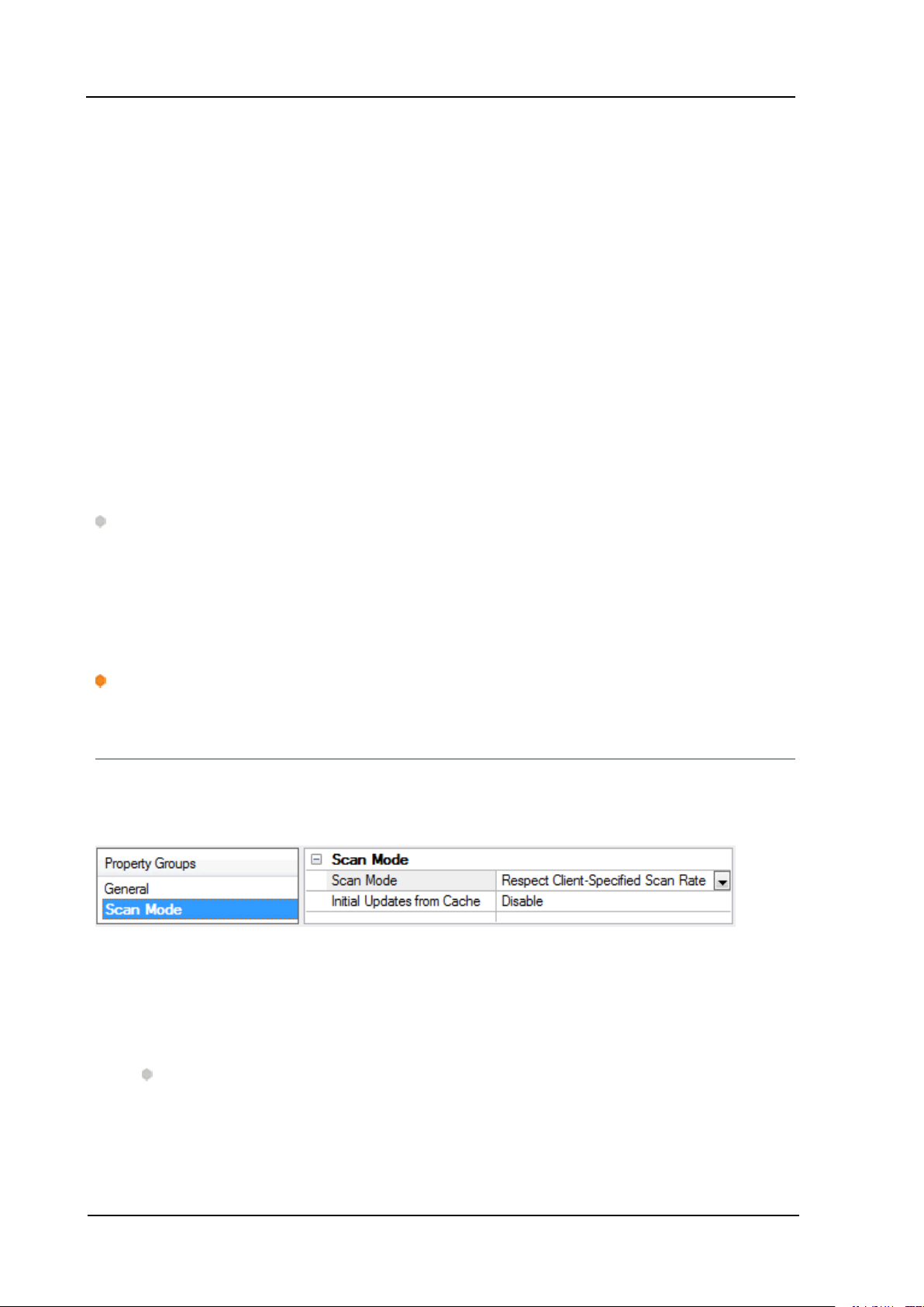
Device Properties - Scan Mode
The Scan Mode specifies the subscribed-client requested scan rate for tags that require device
communications. Synchronous and asynchronous device reads and writes are processed as soon as
possible; unaffected by the Scan Mode properties.
Scan Mode: specifies how tags in the device are scanned for updates sent to subscribed clients.
Descriptions of the options are:
l Respect Client-Specified Scan Rate:This mode uses the scan rate requested by the client.
l Request Data No Faster than Scan Rate:This mode specifies the maximum scan rate to be used.
The valid range is 10 to 99999990 milliseconds. The default is 1000 milliseconds.
Note:When the server has an active client and items for the device and the scan rate value is
increased, the changes take effect immediately. When the scan rate value is decreased, the changes
do not take effect until all client applications have been disconnected.
l Request All Data at Scan Rate:This mode forces tags to be scanned at the specified rate for
subscribed clients. The valid range is 10 to 99999990 milliseconds. The default is 1000 milliseconds.
www. kepware.com

Toyopuc PC3/PC2 Ethernet Driver
l Do Not Scan, Demand Poll Only:This mode does not periodically poll tags that belong to the
device nor perform a read to get an item's initial value once it becomes active. It is the client's
responsibility to poll for updates, either by writing to the _DemandPoll tag or by issuing explicit device
reads for individual items. For more information, refer to "Device Demand Poll" in server help.
l Respect Tag-Specified Scan Rate:This mode forces static tags to be scanned at the rate specified
in their static configuration tag properties. Dynamic tags are scanned at the client-specified scan
rate.
Initial Updates from Cache: When enabled, this option allows the server to provide the first updates for
newly activated tag references from stored (cached) data. Cache updates can only be provided when the
new item reference shares the same address, scan rate, data type, client access, and scaling properties. A
device read is used for the initial update for the first client reference only. The default is disabled; any time a
client activates a tag reference the server attempts to read the initial value from the device.
Device Properties - Timing
The device Communications Timeouts properties allow the driver's response to error conditions to be
tailored to fit the application's needs. In many cases, the environment requires changes to these properties
for optimum performance. Factors such as electrically generated noise, modem delays, and poor physical
connections can influence how many errors or timeouts a communications driver encounters.
Communications Timeouts properties are specific to each configured device.
12
Communications Timeouts
Connect Timeout:This property (which is used primarily by Ethernet based drivers) controls the amount of
time required to establish a socket connection to a remote device. The device's connection time often takes
longer than normal communications requests to that same device. The valid range is 1 to 30 seconds. The
default is typically 3 seconds, but can vary depending on the driver's specific nature. If this setting is not
supported by the driver, it is disabled.
Note: Due to the nature of UDP connections, the connection timeout setting is not applicable when
communicating via UDP.
Request Timeout:This property specifies an interval used by all drivers to determine how long the driver
waits for a response from the target device to complete. The valid range is 50 to 9,999,999 milliseconds
(167.6667 minutes). The default is usually 1000 milliseconds, but can vary depending on the driver. The
default timeout for most serial drivers is based on a baud rate of 9600 baud or better. When using a driver
at lower baud rates, increase the timeout to compensate for the increased time required to acquire data.
Retry Attempts:This property specifies how many times the driver retries a communications request
before considering the request to have failed and the device to be in error. The valid range is 1 to 10. The
default is typically 3, but can vary depending on the driver's specific nature. The number of retries
configured for an application depends largely on the communications environment.
www. kepware.com
13
Toyopuc PC3/PC2 Ethernet Driver
Timing
Inter-Request Delay:This property specifies how long the driver waits before sending the next request to
the target device. It overrides the normal polling frequency of tags associated with the device, as well as
one-time reads and writes. This delay can be useful when dealing with devices with slow turnaround times
and in cases where network load is a concern. Configuring a delay for a device affects communications with
all other devices on the channel. It is recommended that users separate any device that requires an interrequest delay to a separate channel if possible. Other communications properties (such as communication
serialization) can extend this delay. The valid range is 0 to 300,000 milliseconds; however, some drivers may
limit the maximum value due to a function of their particular design. The default is 0, which indicates no
delay between requests with the target device.
Note: Not all drivers support Inter-Request Delay. This setting does not appear if it is not supported by the
driver.
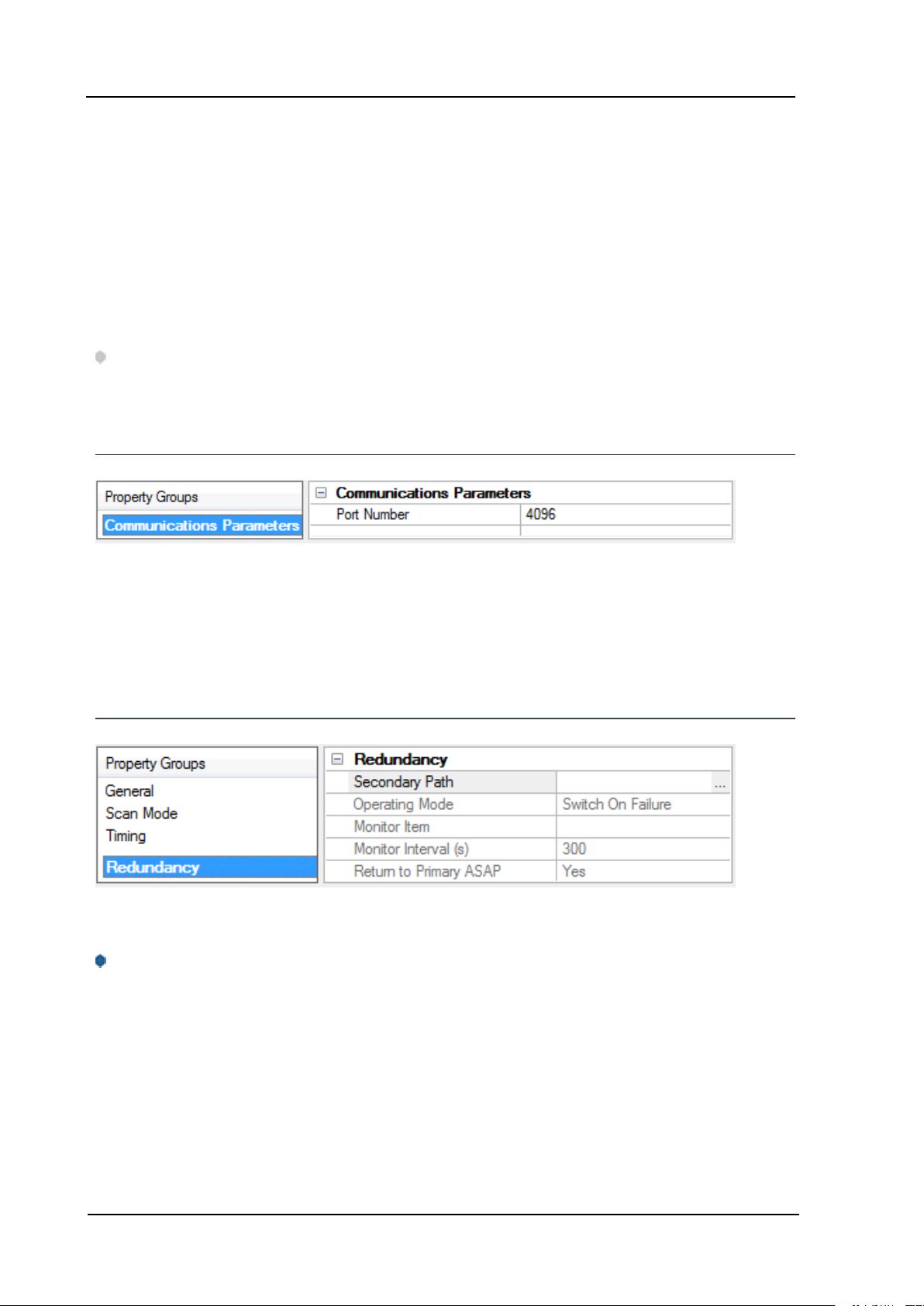
Device Properties - Communications Parameters
Port Number: Specify the port number to be used to connect to the Toyopuc PLC. The Toyopuc EN-I/F
Ethernet PC3/PC2 module supports eight ports for communications. Each port must be dedicated to a single
connection. When specifying a port number, ensure that no other Ethernet node will attempt to use this port
number on the target Toyopuc PLC. The same port number can be used when communicating with multiple
Toyopuc PLCs.
Device Properties - Redundancy
Redundancy is available with the Media-Level Redundancy Plug-in.
Consult the website, a sales representative, or the user manual for more information.
www. kepware.com

Toyopuc PC3/PC2 Ethernet Driver
Diagnostics Tags
Diagnostics Tags provide information on how the Toyopuc PC3/PC2 Ethernet Driver is performing at both
the channel level and device level. At the channel level, diagnostics tags provide information that covers all
operations performed by the driver when communicating with any PLC on the network. At the device level,
diagnostics tags provide information that pertains only to the device under which the diagnostic tags have
been requested.
Channel-Level Diagnostics Tags
Tag Name Functional Description
ChannelReadTime Contains the amount of time in milliseconds required to read all currently
active data for all devices on this channel. This value is a signed long.
ChannelHighTime Contains the amount of time in milliseconds of longest read cycle. This value
is a signed long.
ChannelLowTime Contains the amount of time in milliseconds of shortest read cycle. This value
is a signed long.
ChannelReadsPerformed Contains a count of the reads performed on this channel for all devices. This
is a signed long and will roll over.
ChannelWritesPerformed Contains a count of the writes performed on this channel for all devices. This
is a signed long and will roll over.
ChannelTimeouts Contains a count of the number of timeout/message failures that have
occurred for all devices. The _ChannelTimeouts count is for any error that
may occur on a message attempt. The value does not necessarily indicate
how many messages failed to be sent altogether. It should be used to
diagnose possible communication issues with specific devices. This is a
signed long and will roll over.
14
Device-Level Diagnostics Tags
Tag Name Functional Description
DeviceReadTime Contains the amount of time in milliseconds required to read a block of data
from the specified device. This value is a signed long.
DeviceHighTime Contains the longest amount of time in milliseconds required to read a block of
data from the specified device. This value is a signed long.
DeviceLowTime Contains the shortest amount of time in milliseconds required to read a block
of data from the specified device. This value is a signed long.
DeviceReadsPerformed Contains a count of the reads performed on this device. This is a signed long
and will roll over.
DeviceWritesPerformed Contains a count of the writes performed on this device. This is a signed long
and will roll over.
DeviceTimeouts Contains a count of the number of timeout/message failures that have
occurred on the specified device. The _ DeviceTimeouts count is for any error
that may occur on a message attempt. The value does not necessarily indicate
how many messages failed to be sent altogether. It should be used to diagnose
possible communication issues with this specific device. This is a signed long
and will roll over.
DeviceMultiPointReads Contains a count of the number of multi-point read requests that are currently
being used to acquire all data that is marked for multi-point operation. This tag
can be used to tune multi-point read operation. The goal of course being to
limit the number of multi-point reads being done to the lowest count possible,
www. kepware.com

15
Toyopuc PC3/PC2 Ethernet Driver
Tag Name Functional Description
preferably 1. This is a signed long and will roll over.
Note: All diagnostics tags are Read/Write. The only value that can be written to the tags is zero (which will
clear or reset them).
Multi-Point Read Support
The Toyopuc PLC supports the ability to read data spread randomly throughout the PLC using a single
command. By using this command, users can read crucial data items quickly and efficiently. The Toyopuc
PC3/PC2 Ethernet Driver automatically attempts to make the use of the multi-point command both easy and
efficient. Any memory type that can be acquired by the Toyopuc PC3/PC2 Ethernet Driver can be part of a
multi-point read command. To mark a particular data item to be part of a multi-point request, place the '#'
character in front of any current address. The table below is shown with the addition of the '#' character to
each address. For information on the maximum data that can be read with a multi-point command, refer to
Multi-Point Limitations.
There are some things that should be considered when using the multi-point read functions. The multi-point
command can increase the speed of the data acquisition but if overused, it will need to make multiple multipoint commands to read all the requested data. When this occurs, the overall performance of the driver will
be reduced. The key is to use the multi-point command wisely.
The driver will automatically group data from memory types like bit memory into 16 bit values. For example,
for the PC3 model, if P1-X1, P1-X3, P1-X4, P1-X6, P1-X9, P1-XA, P1-XB are marked as part of a multi-point
read using the '#', users would enter an address of #P1-X1, #P1-X3, #P1-X4, #P1-X6, #P1-X9, #P1-XA, #P1XB. These seven items would be placed into a single 16 bit value; therefore, users would use only one of the
128 16 bit values available in a single multi-point read command. The 7 items were grouped together
because the address of each bit fell within a single 16 bit word value of X memory. If 7 items like #P1-X1,#P1X20,#P1-X55,#P1-X77,#P1-X99,#P1-XAA,#P1-XBB are entered as part of a multi-point read, each bit in this
case would require an entire 16 bit value in the multi-point read command to receive the data. Plan the data
usage in the controller. If possible, make sure that the bits being read are grouped closely. This prudent
planning applies primarily to the bit memory types. Register memory requires a single 16 bit value (two 16
bit values in the case of DWords) for each register that is added to the multi-point read.
By using this information, users can plan the multi-point reads. The Toyopuc PC3/PC2 Ethernet Driver can
perform as many multi-point reads as are needed to acquire all the data that has been marked for multipoint operation. Remember, however, that the driver will run slower when there are many read being run. To
determine how many multi-point read requests the Toyopuc Ethernet PC3PC2 driver is using to acquire all
currently defined multi-point data, use the special diagnostic tag "_DeviceMultiPointReads". For more
information on this tag, refer to Diagnostics.
The multi-point read operation can be combined with the normal data reads of the Toyopuc PC3/PC2
Ethernet Driver. For example, if a block of 50 D registers consecutively ordered is being read, it may be
more efficient to read the 50 D registers as part of a normal block read and save the space in the multi-point
read function for data that is spread more randomly throughout the PLC memory. Use the diagnostics tags
to help determine the most efficient way of acquiring the data for the application.
Multi-Point Limitations
For tags belonging to device models PC3 Device and PC10G Device, the maximum data requested for the
data types are as follows:
Boolean: 1024*
www. kepware.com

Toyopuc PC3/PC2 Ethernet Driver
Byte: 128
Word: 64
DWord: 32
*If contiguous Booleans are requested, the request will be done in one multi-point read.
Combination of any of the above data types in a single multi request has to be within the following limit:
(No. of Booleans/16) + (No. of Bytes/2) + No. of Words + (No. of DWords * 2) <= 64
For tags belonging to device model PC2/PC2 Interchange, the maximum data requested for the data types
are as follows:
Boolean: 2048*
Byte: 256
Word: 128
DWord: 64
*If contiguous booleans are requested, the request will be done in one multi-point read.
Combination of any of the above data types in a single multi request has to be within the following limit:
(No. of Booleans/16) + (No. of Bytes/2) + No. of Words + (No. of DWords * 2) <= 128
16
Memory Types Shown with the Multi-Point Marker
Memory Type Syntax Data Types Access
Edge Relay (P) #P0000-#P01FF
#P000-#P01F
#P000-#P01E
Keeping Relay (K) #K0000-#K02FF
#K000-#K02F
#K000-#K02E
Specific Relay (V) #V0000-#V00FF
#V000-#V0F
#V000-#V0E
Timer Bits (T) #T0000-#T01FF
#T000-#T01F
#T000-#T01E
Count Bits (C) #C0000-#C01FF
#C000-#C01F
#C000-#C01E
Link Relay (L) #L0000-#L07FF
#L000-#L07F
#L000-#L07E
I/O Relay (X) #X0000-#X07FF
#X000-#X07F
#X000-#X07E
I/O Relay (Y) #Y0000-#Y07FF
#Y000-#Y07F
#Y000-#Y07E
Internal Relay (M) #M0000-#M07FF
#M000-#M07F
#M000-#M07E
Boolean
Byte, Word, Short, BCD DWord, Long,
LBCD
Boolean
Byte, Word, Short, BCD DWord, Long,
LBCD
Boolean
Byte, Word, Short, BCD DWord, Long,
LBCD
Boolean
Byte, Word, Short, BCD
DWord, Long, LBCD
Boolean
Byte, Word, Short, BCD DWord, Long,
LBCD
Boolean
Byte, Word, Short, BCD DWord, Long,
LBCD
Boolean
Byte, Word, Short, BCD DWord, Long,
LBCD
Boolean
Byte, Word, Short, BCD DWord, Long,
LBCD
Boolean
Byte, Word, Short, BCD DWord, Long,
LBCD
Read/Write
Read/Write
Read/Write
Read/Write
Read/Write
Read/Write
Read/Write
Read/Write
Read/Write
www. kepware.com

17
Toyopuc PC3/PC2 Ethernet Driver
Memory Type Syntax Data Types Access
Specific Register (S) #S0000-#S03FF
#S0000-#S03FE
Timer/Present Value Register
(N)
Link Register (R) #R0000-#R07FF
Data Register (D) #D0000-#D2FFF
File Register (B) #B0000-#B1FFF
Extended I/O Relay (EX) #EX0000-
Extended I/O Relay (EY) #Y0000-#Y07FF
Extended Internal Relay (EM) #EM0000-
Extended Keep Relay (EK) #EK0000-
Extended Special Relay (EV) #EV0000-
Extended Timer Bits (ET) #ET0000-
Extended Counter Bits (EC) #EC0000-
Extended Link Relay (EL) #EL0000-
Extended Edge Direction (EP) #EP0000-
Extended Data Register (U) #U0000-#U7FFF Byte, Word, Short, BCD DWord, Long, Read/Write
#N0000-#N01FF
#N0000-#N01FE
#R0000-#R07FE
#D0000-#D2FFE
#B0000-#B1FFE
#EX07FF
#EX000-#EX07F
#EX000-#EX07E
#Y000-#Y07F
#Y000-#Y07E
#EM1FFF
#EM000-
#EM1FF
#EM000-
#EM1FE
#EK0FFF
#EK000-#EK0FF
#EK000-#EK0FE
#EV0FFF
#EV000-#EV0FF
#EV000-#EV0FE
#ET07FF
#ET000-#ET07F
#ET000-#ET07E
#EC07FF
#EC000-#EC07F
#EC000-#EC07E
#EL1FFF
#EL000-#EL1FF
#EL000-#EL1FE
#EP0FFF
#EP000-#EP0FF
#EP000-#EP0FE
Byte, Word, Short, BCD DWord, Long,
LBCD
Byte, Word, Short, BCD DWord, Long,
LBCD
Byte, Word, Short, BCD DWord, Long,
LBCD
Byte, Word, Short, BCD DWord, Long,
LBCD
Byte, Word, Short, BCD DWord, Long,
LBCD
Boolean
Byte, Word, Short, BCD DWord, Long,
LBCD
Boolean
Byte, Word, Short, BCD DWord, Long,
LBCD
Boolean
Byte, Word, Short, BCD DWord, Long,
LBCD
Boolean
Byte, Word, Short, BCD DWord, Long,
LBCD
Boolean
Byte, Word, Short, BCD DWord, Long,
LBCD
Boolean
Byte, Word, Short, BCD DWord, Long,
LBCD
Boolean
Byte, Word, Short, BCD DWord, Long,
LBCD
Boolean
Byte, Word, Short, BCD DWord, Long,
LBCD
Boolean
Byte, Word, Short, BCD DWord, Long,
LBCD
Read/Write
Read/Write
Read/Write
Read/Write
Read/Write
Read/Write
Read/Write
Read/Write
Read/Write
Read/Write
Read/Write
Read/Write
Read/Write
Read/Write
www. kepware.com

Toyopuc PC3/PC2 Ethernet Driver
Memory Type Syntax Data Types Access
#U0000-#U7FFE LBCD
Extended Timer/Counter Value
(EN)
Extended Setup Value Register
(H)
Extended Special Register #ES0000-
#EN0000#EN07FF
#EN0000-
#EN07FE
#H0000-#H07FF
#H0000-#H07FE
#ES07FF
#ES0000-
#ES07FE
Byte, Word, Short, BCD DWord, Long,
LBCD
Byte, Word, Short, BCD DWord, Long,
LBCD
Byte, Word, Short, BCD DWord, Long,
LBCD
Read/Write
Read/Write
Read/Write
18
www. kepware.com

19
Data Type Description
Data Type Description
Boolean Single bit
Byte Unsigned 8-bit value
bit 0 is the low bit
bit 7 is the high bit
Word Unsigned 16-bit value
bit 0 is the low bit
bit 15 is the high bit
Short Signed 16-bit value
bit 0 is the low bit
bit 14 is the high bit
bit 15 is the sign bit
DWord Unsigned 32-bit value
Toyopuc PC3/PC2 Ethernet Driver
bit 0 is the low bit
bit 31 is the high bit
Long Signed 32-bit value
bit 0 is the low bit
bit 30 is the high bit
bit 31 is the sign bit
BCD Two byte packed BCD
Value range is 0-9999. Behavior is undefined for values beyond this range.
LBCD Four byte packed BCD
Value range is 0-99999999. Behavior is undefined for values beyond this range.
www. kepware.com

Toyopuc PC3/PC2 Ethernet Driver
Address Descriptions
The Toyopuc PC3 driver supports the PC2 PLC, PC3 PLC and PC10G PLC. When configuring the OPC Server
application, users must choose a PLC model type when defining a device connection. Based on that model
selection, two different PLC data addressing modes will be available to access data within the PLC. Select a
link from the following list to obtain specific address information for the model of interest.
PC2/PC2 Interchange
PC3 Device
PC10G
PC2/PC2 Interchange Mode Address Descriptions
When the PC2 model has been selected, the Toyopuc Computer Link Protocol supports the following
addresses. These address types are only available when using a PC2 PLC or using a PC3 PLC in PC2
Interchange mode. For more information, refer to Addressing Examples.
Note: The valid address range of each memory type depends on the data type being accessed. Please refer
to the Syntax and Data Types columns below. The valid range (syntax) is shown on the same line as the data
type(s). For example, the valid range for Edge Relay is P0000-P01FF if the data type being accessed is
Boolean. If the data type being accessed is byte, word, short or BCD, the valid range is P000-P01F. If the data
type is DWord, Long or LBCD, the valid range is P000-P01E. The default data types for dynamically defined
tags are shown in bold.
20
Memory Type Syntax Data Type Access
Edge Relay (P) P0000-P01FF
P000-P01F
P000-P01E
Keeping Relay (K) K0000-K02FF
K000-K02F
K000-K02E
Specific Relay (V) V0000-V00FF
V000-V0F
V000-V0E
Timer Bits (T) T0000-T01FF
T000-T01F
T000-T01E
Count Bits (C) C0000-C01FF
C000-C01F
C000-C01E
Link Relay (L) L0000-L07FF
L000-L07F
L000-L07E
I/O Relay (X) X0000-X07FF
X000-X07F
X000-X07E
I/O Relay (Y) Y0000-Y07FF
Y000-Y07F
Y000-Y07E
Internal Relay (M) M0000-M07FF Boolean Read/Write
Boolean
Byte*, Word, Short, BCD
DWord, Long, LBCD
Boolean
Byte*, Word, Short, BCD
DWord, Long, LBCD
Boolean
Byte*, Word, Short, BCD
DWord, Long, LBCD
Boolean
Byte*, Word, Short, BCD
DWord, Long, LBCD
Boolean
Byte*, Word, Short, BCD
DWord, Long, LBCD
Boolean
Byte*, Word, Short, BCD
DWord, Long, LBCD
Boolean
Byte*, Word, Short, BCD
DWord, Long, LBCD
Boolean
Byte*, Word, Short, BCD
DWord, Long, LBCD
Read/Write
Read/Write
Read/Write
Read/Write
Read/Write
Read/Write
Read/Write
Read/Write
www. kepware.com

21
Toyopuc PC3/PC2 Ethernet Driver
Memory Type Syntax Data Type Access
M000-M07F
M000-M07E
Specific Register (S) S0000.0...S0000.F-S03FF.0...S03FF.F
S0000-S03FF
S0000-S03FE
Present Value Register
(N)
Link Register (R) R0000.0...R0000.F-R07FF.0...R07FF.F
Data Register (D) D0000.0...D0000.F-D02FFF.0...D2FFF.F
File Register (B) B0000.0...B0000.F-B01FFF.0...B1FFF.F
N0000.0...N0000.F-N01FF.0...N01FF.F
N0000-N01FF
N0000-N01FE
R0000-R07FF
R0000-R07FE
D0000-D2FFF
D0000-D2FFE
B0000-B1FFF
B0000-B1FFE
Byte*, Word, Short, BCD
DWord, Long, LBCD
Boolean
Byte*, Word, Short, BCD
DWord, Long, LBCD
Boolean
Byte*, Word, Short, BCD
DWord, Long, LBCD
Boolean
Byte*, Word, Short, BCD
DWord, Long, LBCD
Boolean
Byte*, Word, Short, BCD
DWord, Long, LBCD
Boolean
Byte*, Word, Short, BCD
DWord, Long, LBCD
Read/Write
Read/Write
Read/Write
Read/Write
Read/Write
*Low/High Byte Modifier
An optional Low (L) or High (H) byte modifier can be appended to any address. This modifier instructs the
driver that the low or high byte of the address word is requested. For more information, refer to Addressing
Examples.
Note: When adding a static tag with a low/high byte modifier, the data type must be set to Byte. For more
information on static vs. dynamic tags consult the OPC Server's online documentation.
Multi-Point Read Support
Multi-point read support allows the Toyopuc Ethernet driver to read data from multiple memory types
(based on program number) in a single request. The multi-point read function is available for both the PC3
and PC2 models and can be used across HPC Link or FL-net modules using relay routing. For more
information, refer to Multi-Point Read Support.
Diagnostics Tags
The Diagnostics Tags provide information on how the Toyopuc Ethernet driver is performing. For more
information, refer to Diagnostic Tags.
Array Support
All memory types support arrays, which can be of any data type. Only the following exceptions apply:
1. Byte arrays are not supported (this also means that low/high byte modifiers cannot be used with
array syntax).
2. Boolean arrays are not supported for bit within word type addresses. For example, addresses like
'S0000.0' cannot be used with array notation. Discrete types support Boolean arrays.
3. Multi-point read is not supported for arrays.
The array size cannot exceed the internal block size of 512 bytes. Array syntax is specified by adding '[r]'
(rows) or '[r][c]' at the end of the address string. [r]: rows, [c]: columns.
www. kepware.com

Toyopuc PC3/PC2 Ethernet Driver
Addressing Examples
1. Request 'Specific Relay FF' from program 1 --> P1-VFF.
2. Request High Byte of 'Data Register 10' --> D10H.
3. Request 'Data Register 1000' --> D1000.
4. Request Long value (2 consecutive 16 bit registers) starting at 'Link Register 7E' in program 1 --> P1L7E@LONG (set data type to Long for static tags, or append '@LONG' to address for dynamic tags.
For more information on static vs. dynamic tags consult the OPC Server online Help.
5. Request 20 bits starting at 'I/O Relay 256' --> X0256[20](set data type to BOOLEAN for static tags, or
append '@BOOLEAN' to address for dynamic tags).
6. Request 24 bits starting at 'Edge Relay 100' --> P0100[4][6](set data type to BOOLEAN for static tags,
or append '@BOOLEAN' to address for dynamic tags).
7. Request 16 words starting at 'Specific Register 64' --> S0064[4][4].
8. Request 50 LBCDs starting at 'File Register 6' --> B0006[50](set data type to LBCD for static tags, or
append '@LBCD' to address for dynamic tags).
22
PC3 Address Descriptions
When the PC3 model has been selected, the Toyopuc Computer Link Protocol supports the following
addresses. These address types are only available when using a PC3 PLC. For more information, refer to
Addressing Examples.
Note: The valid address range of each memory type depends on the data type being accessed. Please refer
to the Syntax and Data Types columns below. The valid range (syntax) is shown on the same line as the data
type(s). For example, the valid range for Edge Relay is P0000-P01FF if the data type being accessed is
Boolean. If the data type being accessed is byte, word, short or BCD, the valid range is P000-P01F. If the data
type is DWord, Long or LBCD, the valid range is P000-P01E. The default data types for dynamically defined
tags are shown in bold.
Memory Type Syntax* Data Type Access
Edge Relay (P) P0000-P01FF
P000-P01F
P000-P01E
Keeping Relay (K) K0000-K02FF
K000-K02F
K000-K02E
Specific Relay (V) V0000-V00FF
V000-V0F
V000-V0E
Timer Bits (T) T0000-T01FF
T000-T01F
T000-T01E
Boolean
Byte**, Word, Short,
BCD
DWord, Long, LBCD
Boolean
Byte**, Word, Short,
BCD
DWord, Long, LBCD
Boolean
Byte**, Word, Short,
BCD
DWord, Long, LBCD
Boolean
Byte**, Word, Short,
BCD
DWord, Long, LBCD
Read/Write
Read/Write
Read/Write
Read/Write
www. kepware.com

23
Toyopuc PC3/PC2 Ethernet Driver
Memory Type Syntax* Data Type Access
Count Bits (C) C0000-C01FF
C000-C01F
C000-C01E
Link Relay (L) L0000-L07FF
L000-L07F
L000-L07E
I/O Relay (X) X0000-X07FF
X000-X07F
X000-X07E
I/O Relay (Y) Y0000-Y07FF
Y000-Y07F
Y000-Y07E
Internal Relay (M) M0000-M07FF
M000-M07F
M000-M07E
Specific Register (S) S0000.0...S0000.F-S03FF.0...S03FF.F
S0000-S03FF
S0000-S03FE
Present Value Register
(N)
Link Register (R) R0000.0...R0000.F-R07FF.0...R07FF.F
Data Register (D) D0000.0...D0000.F-D02FFF.0...D2FFF.F
File Register (B) B0000.0...B0000.F-B01FFF.0...B1FFF.F
Extended I/O Relay (EX) EX0000-EX07FF
Extended I/O Relay (EY) EY0000-EY07FF
N0000.0...N0000.F-N01FF.0...N01FF.F
N0000-N01FF
N0000-N01FE
R0000-R07FF
R0000-R07FE
D0000-D2FFF
D0000-D2FFE
B0000B1FFF
B0000B1FFE
EX000-EX07F
EX000-EX07E
EY000-EY07F
EY000-EY07E
Boolean
Byte**, Word, Short,
BCD
DWord, Long, LBCD
Boolean
Byte**, Word, Short,
BCD
DWord, Long, LBCD
Boolean
Byte**, Word, Short,
BCD
DWord, Long, LBCD
Boolean
Byte**, Word, Short,
BCD
DWord, Long, LBCD
Boolean
Byte**, Word, Short,
BCD
DWord, Long, LBCD
Boolean
Byte**, Word, Short,
BCD
DWord, Long, LBCD
Boolean
Byte**, Word, Short,
BCD
DWord, Long, LBCD
Boolean
Byte**, Word, Short,
BCD
DWord, Long, LBCD
Boolean
Byte**, Word, Short,
BCD
DWord, Long, LBCD
Boolean
Byte**, Word, Short,
BCD
DWord, Long, LBCD
Boolean
Byte**, Word, Short,
BCD
DWord, Long, LBCD
Boolean
Byte**, Word, Short,
BCD
DWord, Long, LBCD
Read/Write
Read/Write
Read/Write
Read/Write
Read/Write
Read/Write
Read/Write
Read/Write
Read/Write
Read/Write
Read/Write
Read/Write
www. kepware.com

Toyopuc PC3/PC2 Ethernet Driver
Memory Type Syntax* Data Type Access
Extended Internal Relay
(EM)
Extended Keep Relay (EK) EK0000-EK0FFF
Extended Special Relay
(EV)
Extended Timer Bits (ET) ET0000-ET07FF
Extended Counter Bits
(EC)
Extended Link Relay (EL) EL0000-EL1FFF
Extended Edge Direction
(EP)
Extended Data Register
(U)
Extended Timer/Counter
Value (EN)
Extended Setup Value
Register (H)
Extended Special
Register (ES)
Extended Input Relay (GX) GX0000-GXFFFF
EM0000-EM1FFF
EM000-EM1FF
EM000-EM1FE
EK000-EK0FF
EK000-EK0FE
EV0000-EV0FFF
EV000-EV0FF
EV000-EV0FE
ET000-ET07F
ET000-ET07E
EC0000-EC07FF
EC000-EC07F
EC000-EC07E
EL000-EL1FF
EL000-EL1FE
EP0000-EP0FFF
EP000-EP0FF
EP000-EP0FE
U0000.0...U0000.F -U07FFF.0...U7FFF.F
U0000-U7FFF
U0000-U7FFE
EN0000.0...EN0000.FEN07FF.0...EN07FF.F
EN0000-EN07FF
EN0000-EN07FE
H0000.0...H0000.F-H07FF.0...H07FF.F
H0000-H07FF
H0000-H07FE
ES0000.0...ES0000.FES07FF.0...ES07FF.F
ES0000-ES07FF
ES0000-ES07FE
GX000-GX0FFF
GX000-GX0FFE
Boolean
Byte**, Word, Short,
BCD
DWord, Long, LBCD
Boolean
Byte**, Word, Short,
BCD
DWord, Long, LBCD
Boolean
Byte**, Word, Short,
BCD
DWord, Long, LBCD
Boolean
Byte**, Word, Short,
BCD
DWord, Long, LBCD
Boolean
Byte**, Word, Short,
BCD
DWord, Long, LBCD
Boolean
Byte**, Word, Short,
BCD
DWord, Long, LBCD
Boolean
Byte**, Word, Short,
BCD
DWord, Long, LBCD
Boolean
Byte**, Word, Short,
BCD
DWord, Long, LBCD
Boolean
Byte**, Word, Short,
BCD
DWord, Long, LBCD
Boolean
Byte**, Word, Short,
BCD
DWord, Long, LBCD
Boolean
Byte**, Word, Short,
BCD
DWord, Long, LBCD
Boolean
Byte**, Word, Short,
BCD
DWord, Long, LBCD
Read/Write
Read/Write
Read/Write
Read/Write
Read/Write
Read/Write
Read/Write
Read/Write
Read/Write
Read/Write
Read/Write
Read/Write
24
www. kepware.com

25
Toyopuc PC3/PC2 Ethernet Driver
Memory Type Syntax* Data Type Access
Extended Output Relay
(GY)
Extended Internal Relay
(GM)
GY0000-GYFFFF
GY000-GY0FFF
GY000-GY0FFE
GM0000-GMFFFF
GM000-GM0FFF
GM000-GM0FFE
Boolean
Byte**, Word, Short,
BCD
DWord, Long, LBCD
Boolean
Byte**, Word, Short,
BCD
DWord, Long, LBCD
*Syntax
Addresses should be prefixed with "P1-", "P2-" or "P3-" to denote which PLC program in the PC3 contains the
desired address. For example, to read data register D10 from program 2 in the PC3, use the following
address syntax: P2-D10. If the device is in PC2 Interchange mode, use "P1-" to reference data.
Note: The extended addresses do not use the "P1-", "P2-", or "P3-" program indicator. If that is done, an
error message will be generated in the OPC server message window. Extended addresses must be entered
without any program number. For example, to request Extended I/O Relay (EX) 6FF, use the following syntax:
EX6FF.
Read/Write
Read/Write
**Low/High Byte Modifier
An optional Low (L) or High (H) byte modifier can be appended to any address. This modifier instructs the
driver that the low or high byte of the address word is requested. For more information, refer to Addressing
Examples.
Note: When adding a static tag with a low/high byte modifier, the data type must be set to Byte. For more
information on static vs. dynamic tags, consult the OPC Server online help.
Multi-Point Read Support
Multi-point read support allows the Toyopuc Ethernet driver to read data from multiple memory types
(based on program number) in a single request. The multi-point read function is available for both the PC3
and PC2 models and can be used across HPC Link or FL-net modules using relay routing. For more
information, refer to Multi-Point Read Support.
Diagnostics Tags
The Diagnostics Tags provide information on how the Toyopuc PC3/PC2 Ethernet Driver is performing. For
more information, refer to Diagnostic Tags.
Array Support
All memory types support arrays, which can be of any data type. Only the following exceptions apply:
l Byte arrays are not supported (this also means that low/high byte modifiers cannot be used with
array syntax).
l Boolean arrays are not supported for bit within word type addresses. For example, addresses like
'S0000.0' cannot be used with array notation. Discrete types support Boolean arrays.
l Multi-point read is not supported for arrays.
The array size cannot exceed the internal block size of 512 bytes. Array syntax is specified by adding '[r]'
(rows) or '[r][c]' at the end of the address string. [r]: rows, [c]: columns.
Addressing Examples
www. kepware.com

Toyopuc PC3/PC2 Ethernet Driver
1. Request 'Specific Relay FF' from program 1 --> P1-VFF.
2. Request High Byte of 'Data Register 10' from program 2 --> P2-D10H.
3. Request Data Register 1000 from program 3 --> P3-D1000.
4. Request Extended I/O Relay 6FF --> EX6FF.
5. Request Long value (2 consecutive 16 bit registers) starting at 'Link Register 7E' in program 1 --> P1L7E@LONG (set data type to Long for static tags, or append '@LONG' to address for dynamic tags.
For more information on static vs. dynamic tags consult the OPC Server online Help.
6. Request 20 bits starting at 'I/O Relay 256' from program 2 --> P2-X0256[20] (set data type to
BOOLEAN for static tags, or append '@BOOLEAN' to address for dynamic tags).
7. Request 24 bits starting at 'Edge Relay 100' from program 1 --> P1-P0100[4][6] (set data type to
BOOLEAN for static tags, or append '@BOOLEAN' to address for dynamic tags).
8. Request 16 words starting at 'Specific Register 64' from program 3 --> P3-S0064[4][4].
9. Request 50 LBCDs starting at 'File Register 6' from program 1 --> P1-B0006[50](set data type to
LBCD for static tags, or append '@LBCD' to address for dynamic tags).
26
PC10G Address Descriptions
When the PC10G model has been selected, the Toyopuc Computer Link Protocol supports the following
addresses. These address types are only available when using a PC10G PLC. For more information, refer to
Addressing Examples.
Note 1: The PC10G model also accepts arrays. For example, U0000[2][2].
Note 2: The valid address range of each memory type depends on the data type being accessed. Please
refer to the Syntax and Data Types columns below. The valid range (syntax) is shown on the same line as the
data type(s). For example, the valid range for Edge Relay is P0000-P01FF if the data type being accessed is
Boolean. If the data type being accessed is byte, word, short or BCD, the valid range is P000-P01F. If the data
type is DWord, Long or LBCD, the valid range is P000-P01E. The default data types for dynamically defined
tags are shown in bold.
Memory Type Syntax* Data Type Access
Edge Relay (P) P000-P1FF
P00-P1F
P00-P1E
Edge Relay (P) P1000-P17FF
P100-P17F
P100-P17E
Keeping Relay (K) K000-K2FF
K00-K0F
K00-K0E
Specific Relay (V) V00-VFF
V0-VF
V0-VE
Specific Relay (V) V1000-V17FF
V100-V17F
Boolean
Byte**, Word, Short, BCD
DWord, Long, LBCD
Boolean
Byte**, Word, Short, BCD
DWord, Long, LBCD
Boolean
Byte**, Word, Short, BCD
DWord, Long, LBCD
Boolean
Byte**, Word, Short, BCD
DWord, Long, LBCD
Boolean
Byte**, Word, Short, BCD
Read/Write
Read/Write
Read/Write
Read/Write
Read/Write
www. kepware.com

27
Toyopuc PC3/PC2 Ethernet Driver
Memory Type Syntax* Data Type Access
V100-V17E DWord, Long, LBCD
Timer Bits (T) T000-T1FF
T00-T1F
T00-T1E
Timer Bits (T) T1000-T17FF
T100-T17F
T100-T17E
Count Bits (C) C000-C1FF
C00-C1F
C00-C1E
Count Bits (C) C1000-C17FF
C100-C17F
C100-C17E
Link Relay (L) L000-L7FF
L00-L7F
L00-L7E
Link Relay (L) L1000-L2FFF
L100-L2FF
L100-L2FE
I/O Relay (X) X000-X7FF
X00-X7F
X00-X7E
I/O Relay (Y) Y000-Y7FF
Y00-Y7F
Y00-Y7E
Internal Relay (M) M000-M7FF
M00-M7F
M00-M7E
Internal Relay (M) M1000-M17FF
M100-M17F
M100-M17E
Specific Register (S) S000.0-S3FF.F
S000-S3FF
S000-S3FE
Specific Register (S) S1000.0-S13FF.F
S1000-S13FF
S1000-S13FE
Present Value Register
(N)
Present Value Register
(N)
Link Register (R) R000.0-R7FF.F
Data Register (D) D0000.0-D2FFF.F Boolean Read/Write
N000.0-N1FF.F
N000-N1FF
N000-N1FE
N1000.0-N17FF.F
N1000-N17FF
N1000-N17FE
R000-R7FF
R000-R7FE
Boolean
Byte**, Word, Short, BCD
DWord, Long, LBCD
Boolean
Byte**, Word, Short, BCD
DWord, Long, LBCD
Boolean
Byte**, Word, Short, BCD
DWord, Long, LBCD
Boolean
Byte**, Word, Short, BCD
DWord, Long, LBCD
Boolean
Byte**, Word, Short, BCD
DWord, Long, LBCD
Boolean
Byte**, Word, Short, BCD
DWord, Long, LBCD
Boolean
Byte**, Word, Short, BCD
DWord, Long, LBCD
Boolean
Byte**, Word, Short, BCD
DWord, Long, LBCD
Boolean
Byte**, Word, Short, BCD
DWord, Long, LBCD
Boolean
Byte**, Word, Short, BCD
DWord, Long, LBCD
Boolean
Byte**, Word, Short, BCD
DWord, Long, LBCD
Boolean
Byte**, Word, Short, BCD
DWord, Long, LBCD
Boolean
Byte**, Word, Short, BCD
DWord, Long, LBCD
Boolean
Byte**, Word, Short, BCD
DWord, Long, LBCD
Boolean
Byte**, Word, Short, BCD
DWord, Long, LBCD
Read/Write
Read/Write
Read/Write
Read/Write
Read/Write
Read/Write
Read/Write
Read/Write
Read/Write
Read/Write
Read/Write
Read/Write
Read/Write
Read/Write
Read/Write
www. kepware.com

Toyopuc PC3/PC2 Ethernet Driver
Memory Type Syntax* Data Type Access
D0000-D2FFF
D0000-D2FFE
FB Escape Area (JL) JL0000.0-JL1FFF.F
JL0000-JL1FFF
JL0000-JL1FFE
SFC (JS) JS0000.0-JSFFF.F
JS0000-JSFFF
JS0000-JSFFE
Extended I/O Relay
(EX)
Extended I/O Relay
(EY)
Extended Internal Relay
(EM)
Extended Keep Relay
(EK)
Extended Special Relay
(EV)
Extended Timer Bits
(ET)
Extended Counter Bits
(EC)
Extended Link Relay
(EL)
Extended Edge Direction
(EP)
Extended Data Register
(U)
Extended Timer/Counter
Value (EN)
Extended Setup Value
Register (H)
Extended Special Register
(ES)
EX000-EX7FF
EX00-EX7F
EX00-EX7E
EY000-EY7FF
EY00-EY7F
EY00-EY7E
EM0000-EM1FFF
EM000-EM1FF
EM000-EM1FE
EK000-EKFFF
EK00-EKFF
EK00-EKFE
EV000-…
EV00-EVFF
EV00-EVFE
ET000-ET7FF
ET00-ET7F
ET00-ET7E
EC000-EC7FF
EC00-EC7F
EC00-EC7E
EL0000-EK1FFF
EL000-EK1FF
EL000-EK1FE
EP000-EPFFF
EP00-EPFF
EP00-EPFE
U000000-U1FFFF.F
U00000-U1FFFF
U00000-U1FFFE
EN0000-EN7FFF
EN000-EN7FF
EN000-EN7FE
H0000-H7FFF
H000-H7FF
H000-H7FE
ES0000-ES7FFF
ES000-ES7FF
ES000-ES7FE
Byte**, Word, Short, BCD
DWord, Long, LBCD
Boolean
Byte**, Word, Short, BCD
DWord, Long, LBCD
Boolean
Byte**, Word, Short, BCD
DWord, Long, LBCD
Boolean
Byte**, Word, Short, BCD
DWord, Long, LBCD
Boolean
Byte**, Word, Short, BCD
DWord, Long, LBCD
Boolean
Byte**, Word, Short, BCD
DWord, Long, LBCD
Boolean
Byte**, Word, Short, BCD
DWord, Long, LBCD
Boolean
Byte**, Word, Short, BCD
DWord, Long, LBCD
Boolean
Byte**, Word, Short, BCD
DWord, Long, LBCD
Boolean
Byte**, Word, Short, BCD
DWord, Long, LBCD
Boolean
Byte**, Word, Short, BCD
DWord, Long, LBCD
Boolean
Byte**, Word, Short, BCD
DWord, Long, LBCD
Boolean
Byte**, Word, Short, BCD
DWord, Long, LBCD
Boolean
Byte**, Word, Short, BCD
DWord, Long, LBCD
Boolean
Byte**, Word, Short, BCD
DWord, Long, LBCD
Boolean
Byte**, Word, Short, BCD
DWord, Long, LBCD
Read/Write
Read/Write
Read/Write
Read/Write
Read/Write
Read/Write
Read/Write
Read/Write
Read/Write
Read/Write
Read/Write
Read/Write
Read/Write
Read/Write
Read/Write
28
www. kepware.com

29
Toyopuc PC3/PC2 Ethernet Driver
Memory Type Syntax* Data Type Access
Extended Input Relay
(GX)
Extended Output Relay
(GY)
Extended Internal Relay
(GM)
Extended Buffer Register
(EB)
Extended Flash Register
(FR)
GX0000-GXFFFF
GX000-GXFFF
GX000-GXFFE
GY0000-GYFFFF
GY000-GYFFF
GY000-GYFFE
GM0000-GMFFFF
GM000-GMFFF
GM000-GMFFE
EB00000.0EB3FFFF.F
EB00000-EB3FFFF
EB00000-EB3FFFE
FR000000.0FR1FFFFF.F
FR000000-FR1FFFFF
FR000000-FR1FFFFE
Boolean
Byte***, Word, Short, BCD
DWord, Long, LBCD
Boolean
Byte**, Word, Short, BCD
DWord, Long, LBCD
Boolean
Byte**, Word, Short, BCD
DWord, Long, LBCD
Boolean
Byte**, Word, Short, BCD
DWord, Long, LBCD
Boolean
Byte**, Word, Short, BCD
DWord, Long, LBCD
Read/Write
Read/Write
Read/Write
Read/Write
Read/Write
*Syntax
Addresses should be prefixed with "P1-", "P2-" or "P3-" to denote which PLC program in the PC3 contains the
desired address. For example, to read data register D10 from program 2 in the PC3, use the following
address syntax: P2-D10. If the device is in PC2 Interchange mode, use "P1-" to reference data.
Note: The extended addresses do not use the "P1-", "P2-", or "P3-" program indicator. If that is done, an
error message will be generated in the OPC server message window. Extended addresses must be entered
without any program number. For example, to request Extended I/O Relay (EX) 6FF, use the following syntax:
EX6FF.
**Low/High Byte Modifier
An optional Low (L) or High (H) byte modifier can be appended to any address. This modifier instructs the
driver that the low or high byte of the address word is requested. For more information, refer to Addressing
Examples.
Note: When adding a static tag with a low/high byte modifier, the data type must be set to Byte. For more
information on static vs. dynamic tags, consult the OPC Server's online documentation.
Multi-Point Read Support
Multi-point read support allows the Toyopuc Ethernet driver to read data from multiple memory types
(based on program number) in a single request. The multi-point read function is available for the PC10G
model and can be used across HPC Link or FL-net modules using relay routing.For more information, refer to
Multi-Point Read Support.
Diagnostics Tags
Diagnostics tags provide information on how the Toyopuc PC3/PC2 Ethernet Driver is performing. For more
information, refer to Diagnostic Tags.
Array Support
All memory types support arrays, which can be of any data type. The following exceptions apply:
l Byte arrays are not supported (this also means that low/high byte modifiers cannot be used with
array syntax).
www. kepware.com

Toyopuc PC3/PC2 Ethernet Driver
l Boolean arrays are not supported for bit-within-word type addresses. For example, 'S0000.0' cannot
be used with array notation. Discrete types support Boolean arrays.
l Multi-point read is not supported for arrays.
The array size cannot exceed the internal block size of 512 bytes. Array syntax is specified by adding '[r]'
(rows) or '[r][c]' at the end of the address string. [r]: rows, [c]: columns.
Addressing Examples
1. Request 'Specific Relay 100' from program 1 --> P1-V100.
2. Request 'Edge Relay 1000' from program 2 --> P2-P1000.
3. Request High Byte of 'Data Register 10' from program 2 --> P2-D10H.
4. Request Data Register 1000 from program 3 --> P3-D1000.
5. Request Extended I/O Relay 6FF --> EX6FF.
6. Request Extended Buffer Register 17FFF --> EB17FFF.
7. Request Long Value (2 consecutive 16 bit registers) starting at 'Link Register 7F' in program 1 --> P1L7F@LONG (set data type to Long for static tags or append '@LONG' to address for dynamic tags).
30
Note: For more information on static vs. dynamic tags, refer to the OPC Server's help documentation.
www. kepware.com

31
Toyopuc PC3/PC2 Ethernet Driver
Error Descriptions
The following categories of messages may be generated. Click on a link for a list of messages.
Address Validation
Device Status Messages
Device Error Codes
Address Validation
The following error/warning messages may be generated. Click on the link for a description of the message.
Missing address.
Device address <address> contains a syntax error.
Address <address> is out of range for the specified device or register.
Data Type <type> is not valid for device address <address>.
Device address <address> is read only.
Array size is out of range for address <address>.
Array support is not available for the specified address: <address>.
Missing address.
Error Type:
Warning
Possible Cause:
A tag address that has been specified dynamically has no length.
Solution:
Re-enter the address in the client application.
Device address <address> contains a syntax error.
Error Type:
Warning
Possible Cause:
A tag address that has been specified dynamically contains one or more invalid characters.
Solution:
Re-enter the address in the client application.
Address <address> is out of range for the specified device or register
Error Type:
Warning
Possible Cause:
A tag address that has been specified dynamically references a location that is beyond the range of
supported locations for the device.
Solution:
www. kepware.com

Toyopuc PC3/PC2 Ethernet Driver
Verify the address is correct; if it is not, re-enter it in the client application.
Data Type <type> is not valid for device address <address>.
Error Type:
Warning
Possible Cause:
A tag address that has been specified dynamically has been assigned an invalid data type.
Solution:
Modify the requested data type in the client application.
Device address <address> is read only.
Error Type:
Warning
Possible Cause:
A tag address that has been specified dynamically has a requested access mode that is not compatible with
what the device supports for that address.
32
Solution:
Change the access mode in the client application.
Array size is out of range for address <address>.
Error Type:
Warning
Possible Cause:
A tag address that has been specified statically is requesting an array size that is too large for the address
type or block size of the driver.
Solution:
Re-enter the address in the client application to specify either a smaller value for the array or a different
starting point.
Array support is not available for the specified address: <address>.
Error Type:
Warning
Possible Cause:
A tag address that has been specified statically contains an array reference for an address type that doesn't
support arrays.
Solution:
Either re-enter the address in the client application to remove the array reference or correct the address
type.
www. kepware.com

33
Toyopuc PC3/PC2 Ethernet Driver
Device Status Messages
The following error/warning messages may be generated. Click on the link for a description of the message.
Device <device name> is not responding.
Unable to write to <address> on device <device name>.
Device <device name> is not responding.
Error Type:
Serious
Possible Cause:
1. The driver cannot create a socket connection between the device and the Host PC.
2. The response from the device took longer to receive than the amount of time specified in the
"Request Timeout" device setting.
3. The IP address for the device is incorrect.
4. The TCP/IP Port specified in device settings is incorrect.
Solution:
1. Verify that the Ethernet connections between the PC and the network are functional.
2. Increase the Request Timeout setting so that the entire response can be handled.
3. Verify that the Ethernet connections between the device and the network are functional.
4. Verify that the specified IP address matches the Device IP.
5. Verify that the specified TCP/IP Port matches the port used by the device.
Unable to write to <address> on device <device name>.
Error Type:
Serious
Possible Cause:
1. The driver cannot create a socket connection between the device and the Host PC.
2. The IP address for the device is incorrect.
3. The TCP/IP Port specified in device settings is incorrect.
Solution:
1. Verify that the Ethernet connections between the PC and the network are functional.
2. Verify that the Ethernet connections between the device and the network are functional.
3. Verify that the specified IP address matches the Device IP.
4. Verify that the specified TCP/IP Port matches the port used by the device.
www. kepware.com

Toyopuc PC3/PC2 Ethernet Driver
Device Error Codes
The following error/warning messages may be generated. Click on the link for a description of the message.
Device Error Codes
Error Response Data: Error Code Table
Error Response Data: Error Code Table
34
Error
Code
11 Inability to process data because of faulty CPU Module Hardware.
20 Fixed Data (ENQ) within relay command is not "05."
21 Faulty transfer number (there is erroneous transfer byte number within the relay command).
23 Erroneous command code.
24 Erroneous subcommand code.
25 Erroneous command-format data byte.
26 Erroneous function-call operand number.
31 Attempting to write data into the field where any writing is prohibited during a sequence
32 A command that is defeated during a stop continuity is activated during a stop continuity.
33 Attempting to execute a debug function call despite non-debug mode.
34 Access prohibited owing to access-prohibited configuration.
35 Non-executable owing to execution-priority limiting configuration.
36 Non-executable owing to execution-priority limiting configuration by another device.
39 Attempting to start scanning without any reset after writing I/O point-number parameters or I/O
3C During a fatal failure, a command has issued that is not executable during a fatal failure.
3D Non-executable due to competing process while a different-factor command is executed.
3E Non-executable command due to reset existence.
3F Non-executable command due to stop duration.
40 Address of a reading/writing command or of "address+data number" of a command is out of
41 Word/byte number is out of range.
42 Non-designated data is sent.
43 Erroneous function/call operand.
52 Though any timer or counter is employed, a command for reading/writing the set/recent values
66 No reply is sent from link module with the link exchange No. specified by a relay command
70 Non-executable module with the link exchange No. specified by a relay command (owing to
72 No reply is sent from link module with the link exchange No. specified by relay command (owing
73 Multiple relay commands were issued to the same link module from the CPU module and the
Error Description
operation or to use the function call (which is protected from any execution) during a sequence
operation.
allocation point-number parameters.
range.
is issued.
(owing to no existence of specified link module, power OFF, faulty circuit, or etc.).
erroneous link No. designation or faulty link module).
to no existence of specified link module, power OFF, faulty circuit, or etc.).
link module could not process the commands. Send commands again.
www. kepware.com

35
Note: Codes taken from Toyopuc document: TOYOPUC PC3J/PC2J FL/ET-T-V2 Instruction Manual.
Toyopuc PC3/PC2 Ethernet Driver
www. kepware.com

Toyopuc PC3/PC2 Ethernet Driver
Appendix: Configuring Modules
Configing the FL_ET-T-V2 Ethernet Module
Configuration Ladder for EN-I_F Ethernet Module
Configuring the PC10G CPU for Ethernet Connections
Configuring the PC10G-CPU for Ethernet Communications
Before the PC10G-CPU can be used for Ethernet communications, it must be configured using PCWin
version 10 or above. The following example first shows how to configure the built-in Ethernet port L2 and
then shows how to connect to the PC with PCWin to the PC10G-CPU using a USB connection.
1. To start, open PCWIN.
36
www. kepware.com

37
Toyopuc PC3/PC2 Ethernet Driver
2. To setup the communication between PCWin and PC10G-CPU, click Setup | Setup Communication
Module. If it is the first time configuring PCWin, select Addition and then make the selections as
shown below.
3. Next, make sure that the COM_SERV icon (shown on the bottom right side of the screen) appears as
shown below. The red icon indicates that the connection between PCWin and PC10G-CPU hasn't been
established yet. There are two possible solutions:
l Check the cable connections.
l Reinstall the USB driver that came with the PCWin setup.
4. Optional: To monitor PC10G data from PCWin, go to the menu bar and click Option |
Configuration. Then, select Compatibility and make the selections as shown in the image below.
5. Back in the Project Window, select the Project tab. Then, click Parameters | Link Parameter.
www. kepware.com

Toyopuc PC3/PC2 Ethernet Driver
6. Click Link setup(S) and make the following selections:
l Rack No.(R) - Built-in
38
l Slot No. (S) - L2 Link
l Module Name - Ethernet
7. Click OK.
8. Click Detail(D). In this dialog, the following parameters may be specified:
l In Own Node IP Address, set the desired IP address of the Ethernet Port.
l In Own Node Port No., set the desired Port Number. In this example, 4096 is used.
www. kepware.com

39
Toyopuc PC3/PC2 Ethernet Driver
9. Click Sub-Net Mask and Gateway IP Address and specify the desired subnet and gateway settings.
10. Once finished, click OK.
11. Click OK again. Then, click Yes.
www. kepware.com

Toyopuc PC3/PC2 Ethernet Driver
12. Save the project. In this example, the name "TestProject" is used.
Transferring Configuration Settings to the PC10G-CPU
1. Click CPU | Write Data | All Program+Parameter+Comment. Alternatively, click CPU | Write
Data | Parameter. The invoked window should appear as shown below.
Note: If the CPU is in Run Mode, it will need to be stopped. To do so, click CPU | Stop/Release Stop.
40
2. Once the download is complete, the following window should appear.
3. Power cycle the PC10G-CPU for the new settings to take effect.
www. kepware.com

41
Toyopuc PC3/PC2 Ethernet Driver
Configuring the FL/ET-T-V2 Ethernet Module
Before the FL/ET-T-V2 card can be used for communications, it needs to be configured to use PCWIN. At this
point, users should know how to configure PCWIN to connect to the PLC. For more information, refer to the
Toyopuc FL/ET-T-V2 Ethernet Module Users Manual.
1. To start, open PCWIN.
2. Read the existing program and parameters from the PLC by clicking on CPU | Read Data. Select the
proper option.
www. kepware.com

Toyopuc PC3/PC2 Ethernet Driver
42
3. Once the ladder is loaded, click on Project | Parameter and then select I/O Module.
4. Verify that the Ethernet Card is configured in the PLC.
5. Click OK to close.
6. Click Project | Parameter and then double-click on Link Parameter.
www. kepware.com

43
Toyopuc PC3/PC2 Ethernet Driver
7. In the Program No. field, select the program that the configuration will be placed in. Click Link
Setup.
8. In the ProgramName Link dialog, select the Rack No. and Slot No. where the module is located.
9. In the Link module name field, select Ethernet from the drop-down list. Click OK.
10. In the Link Parameter Setup dialog, select the new link. Next, click the Detail button.
11. Enter the card's IP address in the Own Node IP Address field.
www. kepware.com

Toyopuc PC3/PC2 Ethernet Driver
44
12. Check the Used checkbox for Connection1. Up to 8 connections can be configured.
13. In the Open Protocol field, select TCP Destination Non-Specified Passive Open from the drop-
down list.
14. Enter the appropriate value in the Own Node Port No. field. In the example shown below, the
number 4096 has been entered.
www. kepware.com

45
Toyopuc PC3/PC2 Ethernet Driver
15. Now that the connection is configured, click Sub-Net Mask and Gateway IP Address. These values
should be set by the IT Manager. For less complex networks, match the sub-net mask and gateway IP
address that are configured in the PC's network configuration.
16. Click OK when finished.
17. Click on Timers. This dialog allows the Ethernet connection to reset if a network error forces a
dropped connection between the server and the device. By default, the Non-Reception Timer is set to
Disable (which means permanent waiting).
www. kepware.com

Toyopuc PC3/PC2 Ethernet Driver
46
18. Under Non-Reception Timer, click Enable.
19. To set the timer resolution, enter a value in the Set Value field. Under Unit, select seconds or
minutes. A value of less than a minute is recommended. This setting should not be faster than the
poll rate.
20. Click OK to finish.
Configuration Ladder for EN-I/F Ethernet Module
To make multiple connections to the Toyopuc PLC PC2/PC3, users must connect with different Port IDs in
each client connection. To do this, the ports in the ladder program must be initialized. The example below
shows how to initialize the Ethernet card for one connection port. The following properties are assumed:
1. The Ethernet module link number is 3.
2. The PC IP address is being set to 192.168.1.1 (C0,A8,01,01).
3. The module allows 8 connections. This example specifies 1.
4. The port will be opened as "TCP," "passive partner unspecified."
5. The port number for the first connection is 1000h (4096).
www. kepware.com

47
6. The file memory 0th operand corresponds with data register D000.
7. Data Registers D0100–D0105 are used for writing file memory.
Ladder for Initializing the Ethernet Card
Toyopuc PC3/PC2 Ethernet Driver
For more information, refer to the Toyopuc PC2 or PC3 EN-1/F Users Manual.
www. kepware.com

Toyopuc PC3/PC2 Ethernet Driver
Index
A
Address <address> is out of range for the specified device or register 31
Address Descriptions 20, 22
Address Validation 31
Addressing Examples 30
Advanced Channel Properties 9
Array size is out of range for address <address>. 32
Array Support 29
Array support is not available for the specified address:<address>. 32
B
48
BCD 19
Boolean 19
C
Channel Assignment 10
Channel Properties - Ethernet Communications 7
Channel Properties - General 6
Channel Properties - Write Optimizations 8
Communications Parameters 13
Communications Timeouts 12-13
Configuration Ladder for EN-I/F Ethernet Module 46
Configuring the FL/ET-T-V2 Ethernet Module 41
Configuring the PC10G-CPU for Ethernet Communications 36
Connect Timeout 12
D
Data Collection 11
Data Type <type> is not valid for device address <address>. 32
Data Types Description 19
Description 10
Device <device name> is not responding. 33
www. kepware.com

49
Toyopuc PC3/PC2 Ethernet Driver
Device address <address> contains a syntax error. 31
Device address <address> is read only. 32
Device Error Codes 34
Device ID 5
Device Properties - General 9
Device Status Messages 33
Diagnostics 7
Diagnostics Tags 14, 29
Do Not Scan, Demand Poll Only 12
Driver 7, 10
Duty Cycle 8
DWord 19
E
Error Descriptions 31
Error Response Data: Error Code Table 34
I
ID 10
IEEE-754 floating point 9
Initial Updates from Cache 12
Inter-Request Delay 13
L
LBCD 19
Long 19
M
Missing address. 31
Model 10
Multi-Point Read Support 15
www. kepware.com

Toyopuc PC3/PC2 Ethernet Driver
N
Name 10
Network 5
Network Adapter 8
Non-Normalized Float Handling 9
O
Optimization Method 8
Overview 4
P
50
PC10G Address Descriptions 26
PC2/PC2 Interchange Mode Address Descriptions 20
R
Redundancy 13
Request All Data at Scan Rate 11
Request Data No Faster than Scan Rate 11
Request Timeout 12
Respect Client-Specified Scan Rate 11
Respect Tag-Specified Scan Rate 12
Retry Attempts 12
S
Scan Mode 11
Setup 5
Short 19
Simulated 11
U
Unable to write tag <address> on device <device name>. 33
www. kepware.com

51
Toyopuc PC3/PC2 Ethernet Driver
W
Word 19
Write All Values for All Tags 8
Write Only Latest Value for All Tags 8
Write Only Latest Value for Non-Boolean Tags 8
Write Optimizations 8
www. kepware.com
 Loading...