

TOYODenki VF66R Operating Manual

PWM Sine Wave Converter
Operating Manual


3
Table of Contents
Preface ............................................................................................................................................................................................. 6
Be Sure To Read This Before Use .............................................................................................................................................. 7
Safety Notice .................................................................................................................................................................................. 7
Chapter 1 Checking and Inspecting Package .......................................................................................................... 10
1.1. Checking Package and Inspection on Purchase ................................................................................................... 10
Chapter 2 Product Overview ................................................................................................................................................ 12
2.1. Features ........................................................................................................................................................................ 12
2.2. Configuration .............................................................................................................................................................. 12
Chapter 3 How to Install and Connect Converter .............................................................................................. 14
3.1. Installation Environment and How to Install ................................................................................................... 14
3.1.1. Installation Environment ................................................................................................................................ 14
3.1.2. How to Install Converter ................................................................................................................................ 14
3.2. How to Open and Close Front Cover ....................................................................................................................... 16
3.2.1. How to Open Front Cover .................................................................................................................................. 16
3.2.2. How to Close Front Cover ................................................................................................................................ 19
3.3. How to Connect Converter ........................................................................................................................................ 21
3.3.1. How to Connect Converter Terminals ............................................................................................................ 21
3.4. Terminal Specifications .......................................................................................................................................... 23
3.5. Notes for Wiring and Electrical Wire Size ....................................................................................................... 26
3.5.1. Notes for Wiring ............................................................................................................................................... 26
3.5.2. Electrical Wire Size of Input/Output Device and Main Circuit Wires ............................................. 27
3.5.3. Electrical Wire Size of Control Board ...................................................................................................... 28
3.6. AC Filter ...................................................................................................................................................................... 29
3.6.1. AC Reactor ........................................................................................................................................................... 29
3.6.2. AC Filter Capacitor ......................................................................................................................................... 30
Chapter 4 Basic Operating Procedures for Converter ....................................................................................... 31
4.1. Checks before Starting Operation ......................................................................................................................... 31
4.1.1. About the Control Mode.................................................................................................................................... 31
4.1.2. Minimum Parameter Settings ............................................................................................................................ 31
4.1.3. Replacing Control Board <VFC66R-Z> with Spare ...................................................................................... 31
4.2. Basic Operating Procedures from Console ........................................................................................................... 32
4.2.1. Explanation of Display and Operation Keys on Console ........................................................................ 32
4.2.2. What Are Displayed at Power-on .................................................................................................................... 38
4.2.3. Changing Parameter Settings .......................................................................................................................... 39
4.2.4. Checking Operating State ................................................................................................................................ 42
4.2.5. List of Monitor Items ..................................................................................................................................... 43
4.3. Operations on Console .............................................................................................................................................. 47

4
4.4. Start and Stop through External Contact ........................................................................................................... 48
Chapter 5 Explanation of Parameters ....................................................................................................................... 51
5.1. List of Parameter Areas .......................................................................................................................................... 51
5.2. List of Parameters .................................................................................................................................................... 52
5.3. Detailed Explanation of Each Parameter ............................................................................................................. 57
5.3.1. Basic Setting Area ........................................................................................................................................... 57
5.3.2. Area A (filter constant setting area) ...................................................................................................... 59
5.3.3. Area b (operation command related setting area) .................................................................................. 60
5.3.4. Area c (multifunction input/output related setting area) ................................................................ 63
5.3.5. Area d (converter operation setting area) .............................................................................................. 68
5.3.6. Area E (control gain setting area) ............................................................................................................ 70
5.3.7. Area F (protection function/traceback setting area) .......................................................................... 73
5.3.8. Area G (special adjustment area) ................................................................................................................ 77
5.3.9. Area J (setting area for digital communication options) .................................................................. 77
5.3.10. Area L (analog input/output setting area) .............................................................................................. 79
5.3.11. Area n (converter mode/model display area) ............................................................................................ 81
5.3.12. Area o (special adjustment area) ................................................................................................................ 82
5.3.13. Area P (special adjustment area) ................................................................................................................ 82
5.3.14. Area S (converter mode selection and analog input/output adjustment area) ............................... 83
5.4. Operation Using S Area Parameters ....................................................................................................................... 85
5.4.1. How to Clear Protections ................................................................................................................................ 85
5.4.2. Data Transfer from/to External Console Option ...................................................................................... 87
5.4.3. DC Voltage Detection Gain Adjustment ........................................................................................................ 95
5.4.4. Analog Input (2) and (3) Gain and Offset Adjustment .......................................................................... 98
5.4.5. Analog Output (2) and (3) Gain and Offset Adjustment ...................................................................... 103
Chapter 6 Tr o ub l es h oo t in g ....................................................................................................................................... 109
6.1. Protection Messages and Actions ......................................................................................................................... 109
6.1.1. Displays and Behaviors in Protection Display Mode ............................................................................ 109
6.1.2. List of Protection Messages ........................................................................................................................ 110
6.1.3. How to Handle Protection Messages ............................................................................................................ 115
6.2. How to Check Data in Protection Display Mode ............................................................................................... 123
6.2.1. How to Display Protection Operation Data .............................................................................................. 123
6.2.2. List of Data of Protection Operation and Protection History Display ......................................... 124
6.3. How to Reset Protection Display Mode ............................................................................................................... 125
6.4. How to Check Protection History ......................................................................................................................... 126
Chapter 7 Maintenance and Inspection ........................................................................................................... 128
7.1. Periodic Inspection ................................................................................................................................................ 128
7.2. Main Circuit Capacitor/Cooling Fan Replacement Timing ............................................................................. 129
7.3. How to Replace Cooling Fan .................................................................................................................................. 130
7.3.1. How to Remove Cooling Fan ............................................................................................................................ 130
7.3.2. How to Install Cooling Fan .......................................................................................................................... 133

5
7.4. Inspecting and Replacing Main Circuit Capacitor ......................................................................................... 134
7.5. How to Perform Insulation Resistance Test ..................................................................................................... 134
7.6. How to Discard Parts .............................................................................................................................................. 135
Chapter 8 Replacing Control Board .......................................................................................................................... 136
8.1. Tasks Required for Replacing Control Board ................................................................................................... 136
8.2. How to Replace Control Board .............................................................................................................................. 136
8.3. How to Initialize Converter Main Unit ............................................................................................................. 140
Chapter 9 Standard Specifications ...................................................................................................................... 143
9.1. Common Specifications ............................................................................................................................................ 143
9.2. List of Models .......................................................................................................................................................... 144
Chapter 10 Outline Drawing of Converte r ......................................................................................................... 145
10.1. Standard Type ............................................................................................................................................................ 145
10.2. Non-standard Type (Heat Generation Part Protruded Outside) ................................................................... 147
Chapter 11 VF64R Parameter Compatibility Chart .............................................................................................. 148
11.1. Basic Setting Area .................................................................................................................................................. 148
11.2. Area A (filter constant setting area) ............................................................................................................. 148
11.3. Area b (operation command related setting area) ......................................................................................... 148
11.4. Area c (multifunction input/output related setting area) ....................................................................... 149
11.5. Area E (control gain related setting area) ................................................................................................... 149
11.6. Area F (protection function/traceback setting area) ................................................................................. 150
11.7. Area G (setting area for analog input and output) ..................................................................................... 150
11.8. Area J (communication option setting area) ................................................................................................... 150
11.9. Area o (special adjustment area) ....................................................................................................................... 151
11.10. Area P (special adjustment area) ....................................................................................................................... 151
11.11. Area S (converter capacity/DC voltage detection gain area) ................................................................... 151
Chapter 12 Attentions for Contacting Us......................................................................................................... 152
Chapter 13 Industrial Product Warranty .......................................................................................................... 153
13.1. No-charge warranty Period .................................................................................................................................... 153
13.2. Warranty Scope .......................................................................................................................................................... 153
13.2.1. Problem diagnosis ........................................................................................................................................... 153
13.2.2. Repair ................................................................................................................................................................. 153
13.3. Disclaimers ................................................................................................................................................................ 153
13.4. Repair period after product discontinuation ................................................................................................. 153
13.5. Delivery Condition .................................................................................................................................................. 154

6
Preface
Thank you very much for choosing our converter.
This manual describes how to handle a main unit of the converter.
It provides instructions for using the converter, such as how to install, wire, and operate it correctly as
well as handling methods of its protection operation.
Before operating it, be sure to carefully read this manual. Also, keep this manual in an appropriate place so
that operators can always take and read it.
In addition to the standard functions, the converter provides many features. You can build an optimal system
for different applications by using its various functions. In such a case, use the values described in the
dedicated "Operating Instructions" and "Test Report" for the function.
When delivering any of your products with our converter built in, consider that this manual can be distributed
to end users. Also, when changing our factory default initialized data (hereinafter referred to as
Initialize.Val) for setting parameters of the converter, make sure that end users can be informed about the
changed contents of the Initialize.Val.
Product Overview
Connecting VF66R to an inverter causes the regenerative energy from the motor to return to the power supply
efficiently, which results in energy saving. Also, the power supply harmonics generated from an inverter can
be suppressed significantly.
VF66R provides the PWM sine wave mode and 120-degree conduction mode.
The 120-degree conduction mode enables regenerative operation without high-speed switching since it energizes
according to the phase of three-phase power supply voltage in turn so that the energization period of each phase
becomes 120 degrees.
7
Be Sure To Read This Before Use
Safety Notice
To use the converter correctly, be sure to completely read this manual and all other attached documents before installation,
operation, maintenance, and inspection.
You need to have a good knowledge of equipment, safety information, and all notices before using the converter.
In this manual, safety notices are ranked as "Danger," "Warning," and "Caution."
Danger
When improper use may cause a dangerous situation, death or serious injury may result, and its danger seems to be very urgent.
Danger
When improper use may cause a dangerous situation, death or serious injury may result, and its danger seems to be very urgent.
Warning
When improper use may cause a dangerous situation, and death or serious injury may result.
Warning
When improper use may cause a dangerous situation, and death or serious injury may result.
Caution
When improper use may cause a dangerous situation, medium-level or minor injury may result, and only physical damage may result.
However, it can cause serious results depending on the situation. Cautions described in this manual are all important. Be sure
to observe them.
Caution
When improper use may cause a dangerous situation, medium-level or minor injury may result, and only physical damage may result.
However, it can cause serious results depending on the situation. Cautions described in this manual are all important. Be sure
to observe them.
8
Caution Installation
● Install the converter on non-inflammables such as metal.
Otherwise, a fire may occur.
● Do not put inflammables near the converter.
Otherwise, a fire may occur.
● 75 kW and higher grade models are heavy. Do not attempt to raise it alone.
Otherwise, you may be injured.
● Do not hold the front cover when transporting the converter.
It may fall, which can result in injury.
● Install the converter in a place which can support its weight.
It may fall, which can result in injury.
● Do not install and operate the converter which is damaged or has a missing part.
Otherwise, you may be injured.
● Do not install the converter in an atmosphere which contains plasticizer such as halogen and DOP (phthalate ester).
Otherwise, it may be damaged.
Danger Wiring
● Before wiring, ensure that the input power supply is OFF and the system is disconnected from the power supply.
Otherwise, electric shock or a fire may occur.
Warning Wiring
● Be sure to connect a ground wire.
Otherwise, electric shock or a fire may occur.
● Electrical engineering technicians should connect wires.
Otherwise, electric shock or a fire may occur.
● Be sure to install the converter before wiring.
Otherwise, electric shock or a fire may occur.
● Do not directly connect a resistor between DC terminals [+]and [-].
Otherwise, a fire may occur.
Warning Operation
● Be sure to install the front cover before turning on the input power. Do not remove the front cover during energization.
Otherwise, it can result in a risk of electric shock.
● Do not use operation keys by wet hands.
Otherwise, it can result in a risk of electric shock.
● Do not touch terminals such as main circuit terminals and a ground terminal during energization.
Otherwise, it can result in a risk of electric shock.
● The stop button ([STOP/RESET] key) is enabled only when functions have been set. Provide an emergency stop button separately.
Otherwise, you may be injured.
When alarm reset is performed with operation signals input, the converter suddenly restarts. Check that signals are turned off,
and then perform alarm reset.
Otherwise, you may be injured.
9
Caution Operation
● Do not touch a heat sink and a discharge resistor because they reach high temperatures.
Otherwise, you may get burned.
Warning Maintenance and inspection, and replacement of parts
● Before inspection, turn off the input power after checking that the operation is stopped, and then wait for over ten minutes.
Also, check that DC voltage between the DC terminals [+] and [-]is less than or equal to 30 V.
Otherwise, electric shock, injury, or a fire may occur.
● Do not perform maintenance and inspection or replace parts by anyone except qualified persons. Use a tool for insulation
for maintenance and inspection.
Otherwise, electric shock or injury may occur.
Warning Others
● Never modify the converter.
Otherwise, electric shock or injury may occur.
Caution General notice
● To provide detailed explanation, all figures described in this manual are sometimes drawn with the cover or a safety shield
removed.
To operate the converter, be sure to return the specified cover or shield to its original position and to follow the procedure
described in this manual.
● When the converter is packed with fumigated wooden materials, its electronic components may be fatally damaged.
Be sure to use ways other than fumigation for sterilization and insect removal. Also, process them before packing.
● These safety notices and specifications in this manual are subject to change without notice.
10
Chapter 1 Checking and Inspecting Package
1.1. Checking Package and Inspection on Purchase
After receiving the converter, check the package, and then inspect the product and accessories.
If you have any problem, contact us or the distributor.
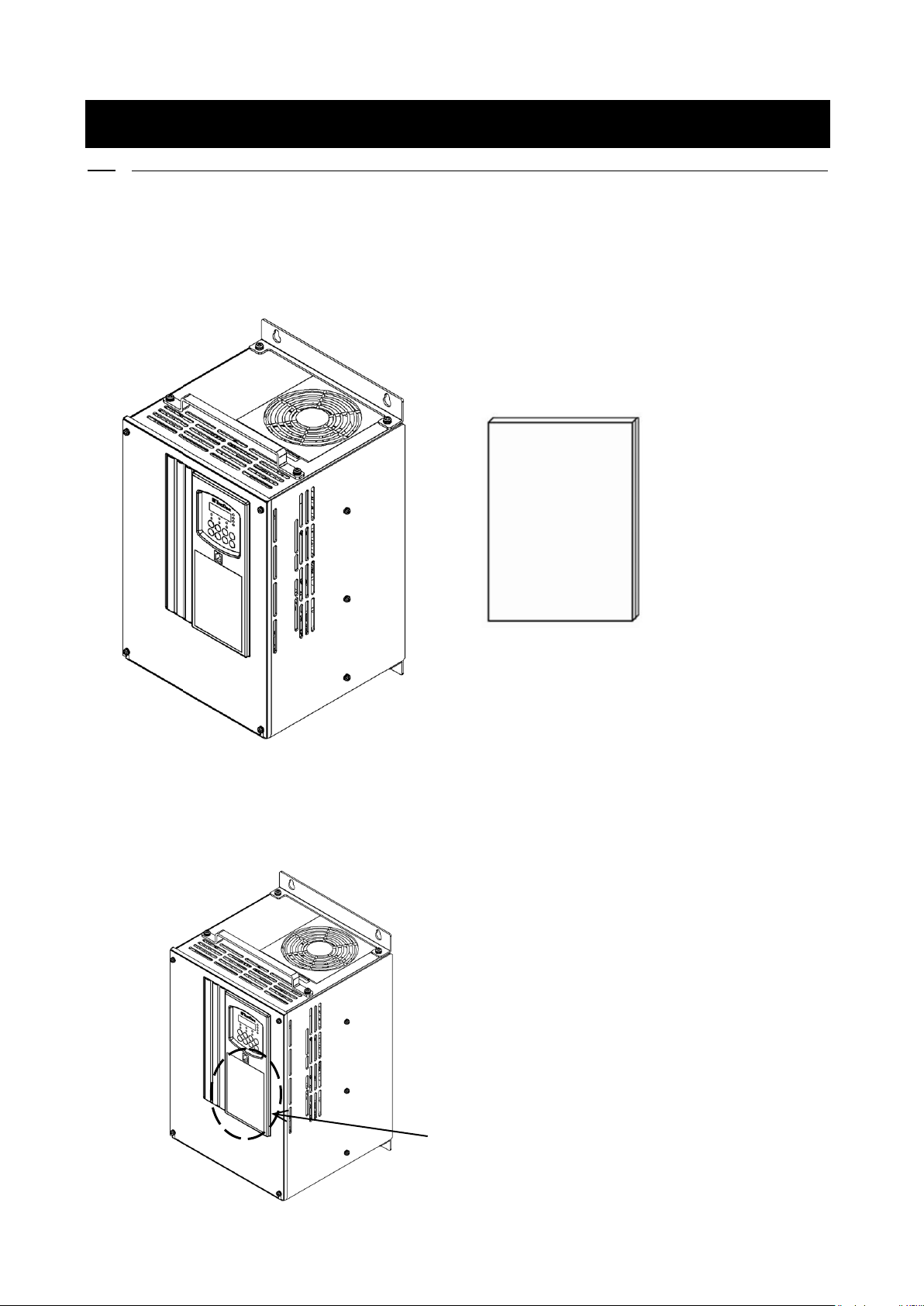
(1) Check that the package contains the converter main unit and "Operating Instructions."
(2) Check that the specifications, accessories, spares, and options are delivered as you order.
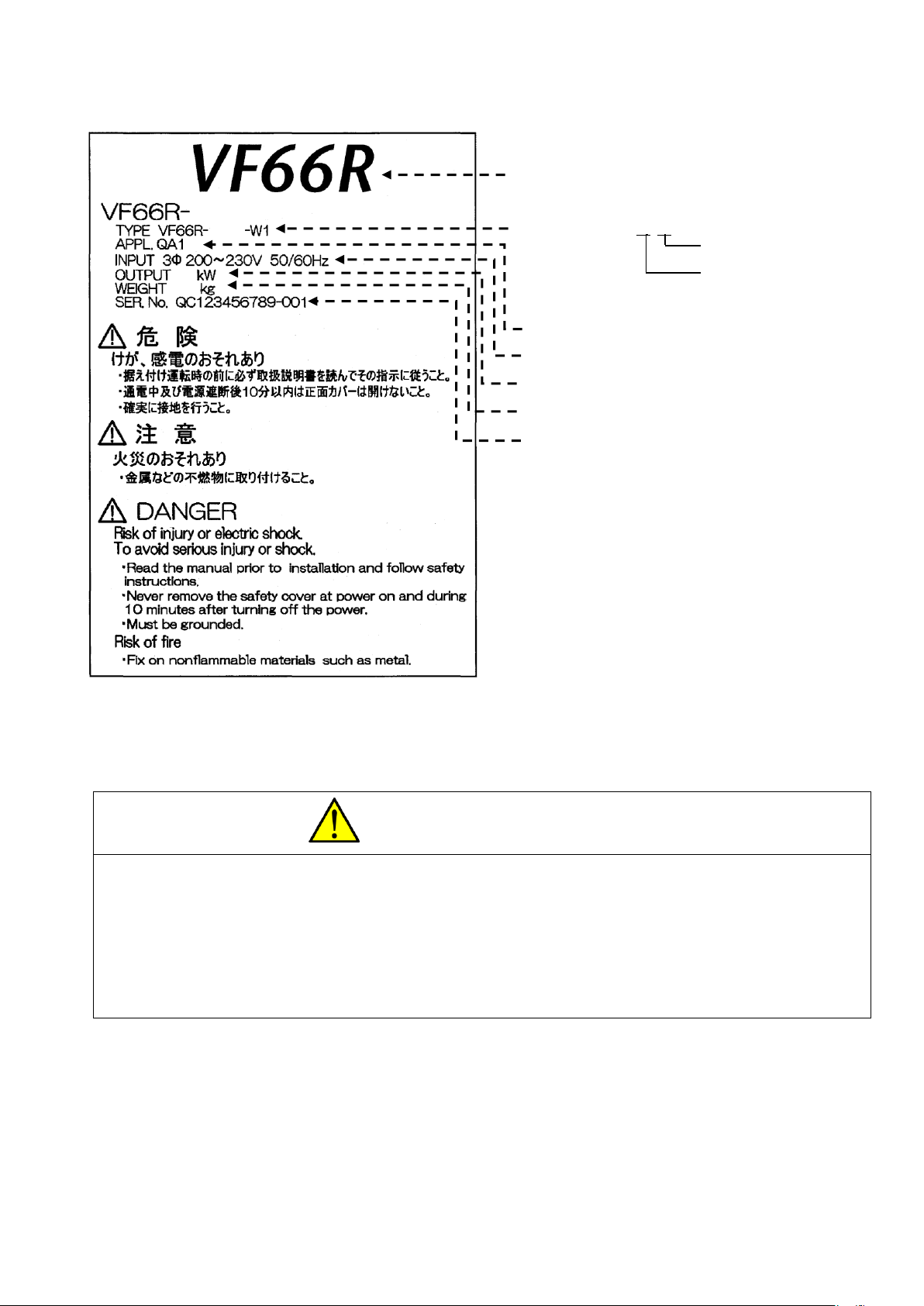
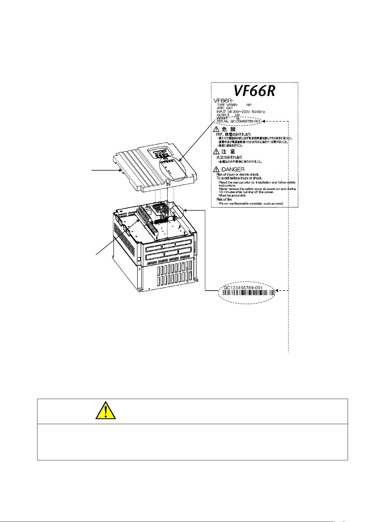
You can check the converter model by seeing the model label on the surface of the cover.
Model label
Converter main unit
Operating Instructions
11
Example of the model label on the cover surface
(3) Check the product for damages and loose or removed screws during transportation.
Caution Safety notice
● To use the converter correctly, read this manual completely.
● Our converter is not designed and produced for the purpose of being used for a device or system under a situation where human
life may be threatened.
● Do not use this converter for special purposes such as riding, medical, aerospace, nuclear power control, and a submarine
repeater or system.
● This converter is produced under the strict quality control. However, when it is applied to an important facility where its
failure might threaten human life or cause expected serious losses, you should install any safety devices to prevent serious
accidents.
● This converter requires electrical work. Electrical engineering technicians should do it.
Applied symbol
Type
Converter series name
(Indicates a sine wave PWM converter)
Model: VF66R-7522-W1
Voltage class
22: 200 V class
44: 400 V class
Input power supply voltage specification
Converter rated output power
Weight
Serial number
7522
7522
69
75
12
Chapter 2 Product Overview
2.1. Features
■ Equipped with the functions designed specially for power supply
Connecting VF66R to an inverter causes the regenerative energy from the motor to return to the power supply
efficiently, which results in energy saving. Also, the power supply harmonics generated from an inverter can
be suppressed significantly.
VF66R provides the PWM sine wave mode and 120-degree conduction mode.
The 120-degree conduction mode enables regenerative operation without high-speed switching since it energizes
in turn according to the phase of three-phase power supply voltage so that the energization period of each phase
becomes 120 degrees.
■ Reduced maintenance cost
Long-life parts are used for components which require replacement.
・ Main circuit capacitor: About ten years (life expectancy in design)
・ Cooling fan: About five years (life expectancy in design)
You can check the replacement timing with a cumulative operation timer.
2.2. Configuration
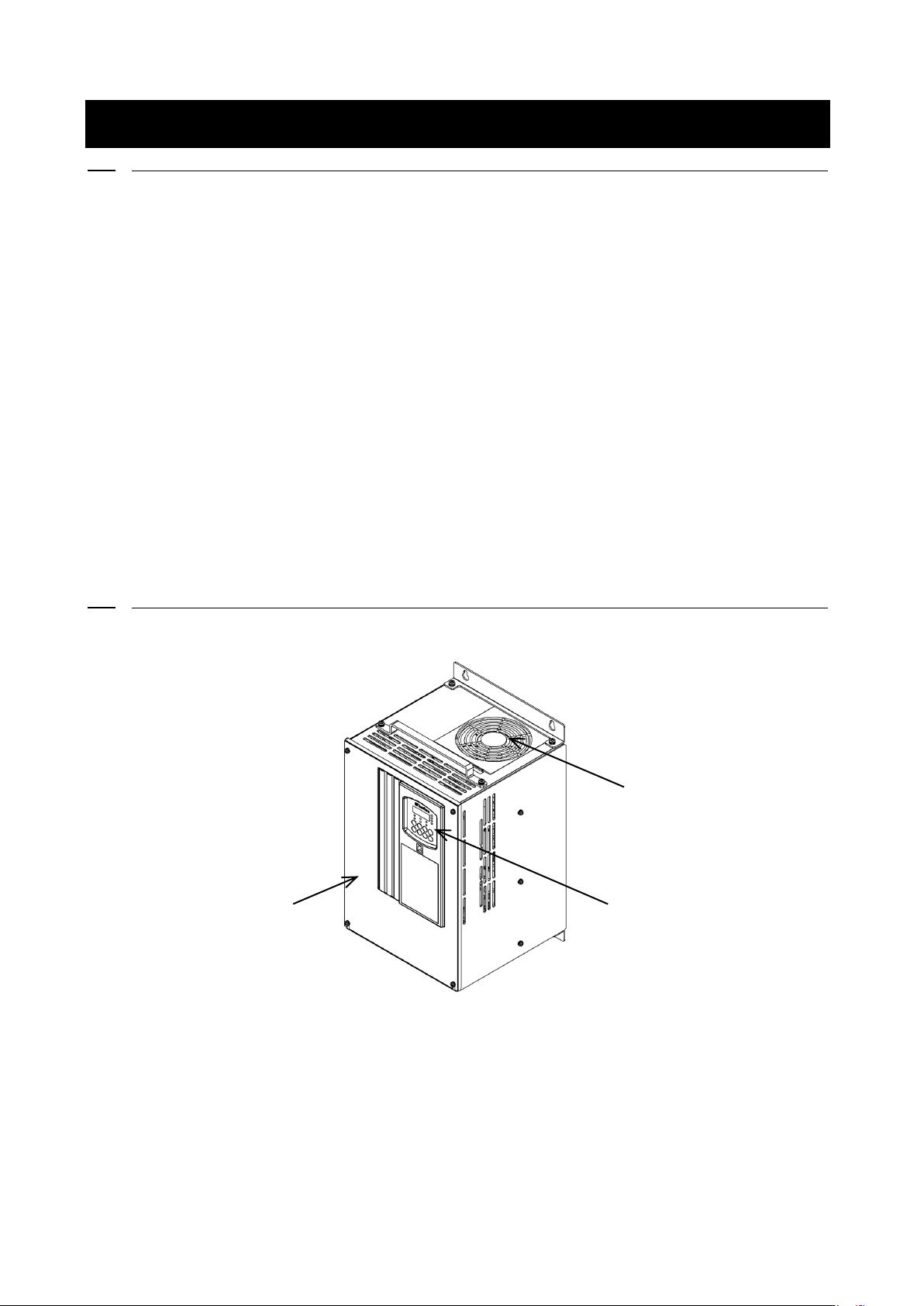
■ Converter main unit
・ Front cover
This is a front cover of the converter. For how to remove it, refer to {3.2.1. How to Open Front Cover}.
・ Cooling fan
This is a fan motor for cooling. For how to replace it, refer to {7.3. How to Replace Cooling Fan}.
・ Console
It is used for operation from the converter main unit.
It consists of a seven-segment display, a unit LED, a status display LED, and operation keys.
For details, refer to {4.1.1. Explanation of Display and Operation Keys on Console}.
Console
Cooling fan
Front cover
13
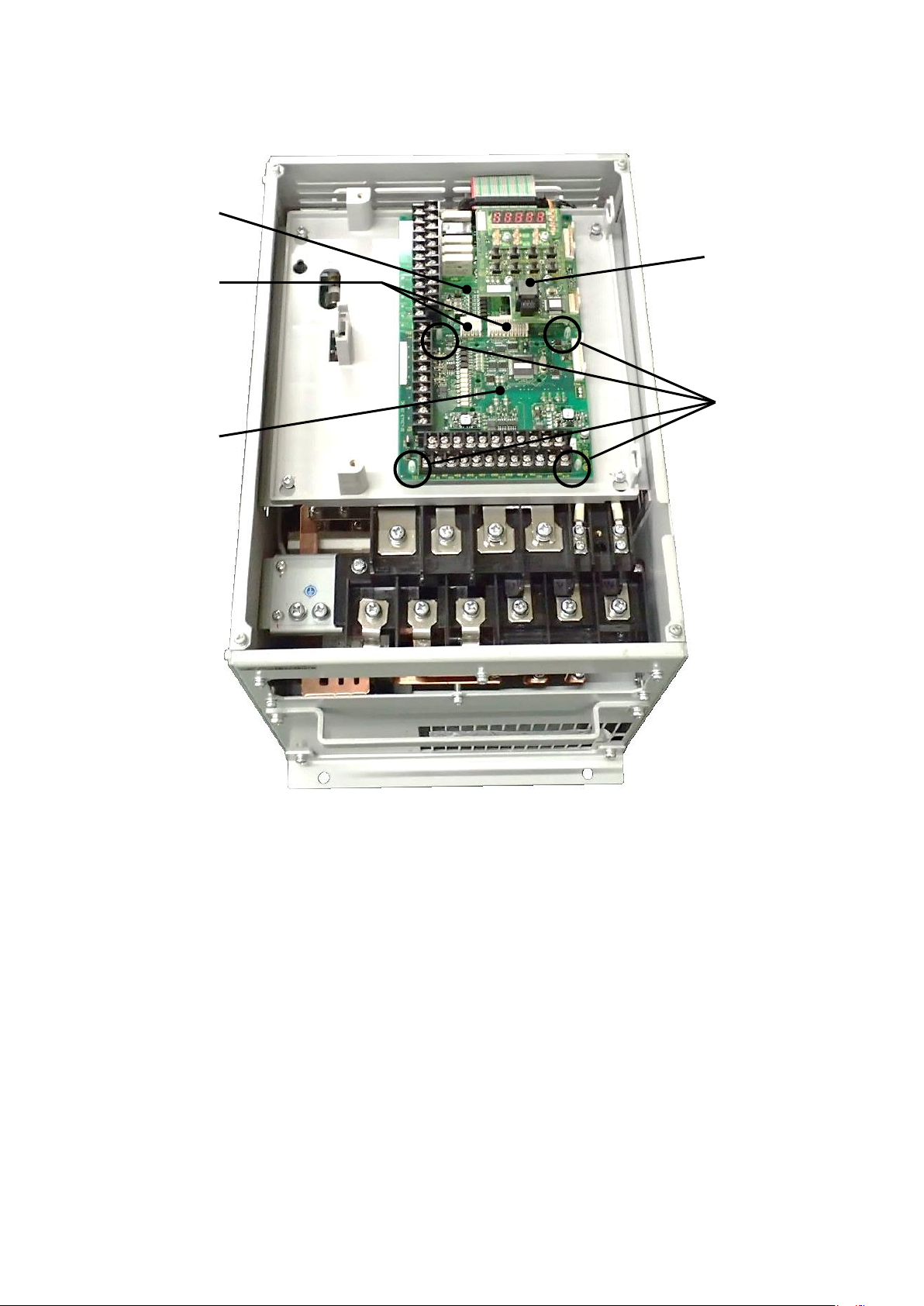
■ Circuit board
・ Terminal block
For details of wiring, refer to {3.3.1. How to Connect Converter Terminals} and {3.5. Notes for Wiring and
Electrical Wire Size}. For details of the terminal block, refer to {3.4. Terminal Specifications}.
・ Control board <VFC66R-Z>
This is a control part of the converter. A terminal block is located on the left side.
For details of wiring, refer to {3.3.1. How to Connect Converter Terminals} and {3.5.3. Electrical Wire Size
of Control Board}. For details of the terminal block, refer to {3.4. Terminal Specifications}. For how to
replace the control board <VFC66R-Z>, refer to {8.2. How to Replace Control Board}.
・ Console board <SET66-Z>
This is a console part of the converter. It has LEDs and operation keys.
・ Optional boards
Optional boards are used to add external input/output, etc.
Console
Board
<SET66-Z>
Connector
Support
Control board
<VFC66R-Z>
Optional board
14
Chapter 3 How to Install and Connect Converter
3.1. Installation Environment and How to Install
3.1.1. Installation Environment
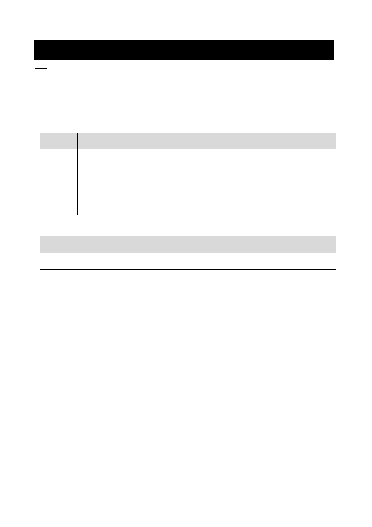
Install the converter in an environment not exceeding the overvoltage category III or the pollution degree 2
defined by the IEC60664-1.
Overvoltage category
Overvoltage
category
Equipment
Equipment overview
I
Secondary circuit
Equipment connecting to a circuit where any measures are taken to
limit transient overvoltage to a lower level. It includes a
protected electronic circuit.
II
Home electrical appliance
and office machine
Equipment consuming energy supplied from a fixed wiring facility.
III
Electrical facility
Equipment in the fixed wiring facility which especially requires
reliability and effectiveness.
IV
Power receiving
Equipment used for a service entrance.
Pollution degree
Pollution
degree
Overview
Specific example
1
There is no pollution, or only dry and non-conductive pollution
occurs. This type of pollution has no effect.
Clean room and others
2
Typically, only non-conductive pollution occurs. However, when the
system is not running, temporary conductivity can be expected due
to condensation.
Electrical equipment in
an office and a control
panel, and others
3
Conductive pollution, or dry and non-conductive pollution resulting
in conductivity due to expected condensation occurs.
In a general factory and
others
4
Pollution causes continuous conductivity due to conductive dust,
rain, and snow.
Outdoor and others
3.1.2. How to Install Converter
■ Requirements of where to install the converter
Installation conditions of the converter will greatly affect its life and reliability. Avoid installing it in
the places listed below. Use it under the environmental conditions described in {Chapter 9 Standard
Specifications}.
(1) In a humid and dusty area or a place where water or oil drips, the insulation of circuits is deteriorated,
which may reduce the life of parts.
(2) Too high ambient temperature will cause the life of the main circuit capacitor or the cooling fan to be
reduced.
(3) In a place containing corrosive gas, connectors may have a loose connection, electrical wires may be
disconnected, and parts may be damaged.
15
(4) In a place having many vibrations, connectors may have a loose connection, electrical wires may be
disconnected, and parts may be damaged.
(5) When using the converter in a place where ambient temperature is below 0 ℃, use a heater, etc. to ensure
that it becomes 0 ℃ or higher at the start of the converter. After it starts, when the temperature becomes
0 ℃ or higher due to its heat generation, there is no problem.
■ Action after short-circuit
Dispose of a short-circuited converter in any circumstances without using it.
Caution Installation
● Install the converter on non-inflammables such as metal.
Otherwise, a fire may occur.
● Do not put inflammables near the converter.
Otherwise, a fire may occur.
● 22 kW and higher grade models are heavy. Do not attempt to raise it alone.
Otherwise, you may be injured.
● Do not hold the front cover when transporting the converter.
It may fall, which can result in injury.
● Install the converter in a place which can support its weight.
It may fall, which can result in injury.
● Do not install and operate the converter which is damaged or has a missing part.
Otherwise, you may be injured.
● Do not install the converter in an atmosphere which contains plasticizer such as halogen and DOP (phthalate ester).
Otherwise, it may be damaged.
■ Converter installation requirements and heat radiation
To use the converter, incorporate it into the control board, etc. to meet the environmental conditions for
installation.
Warning How to install converter
● Install it correctly.
Incorrect installation can result in a risk of electric shock or a fire.
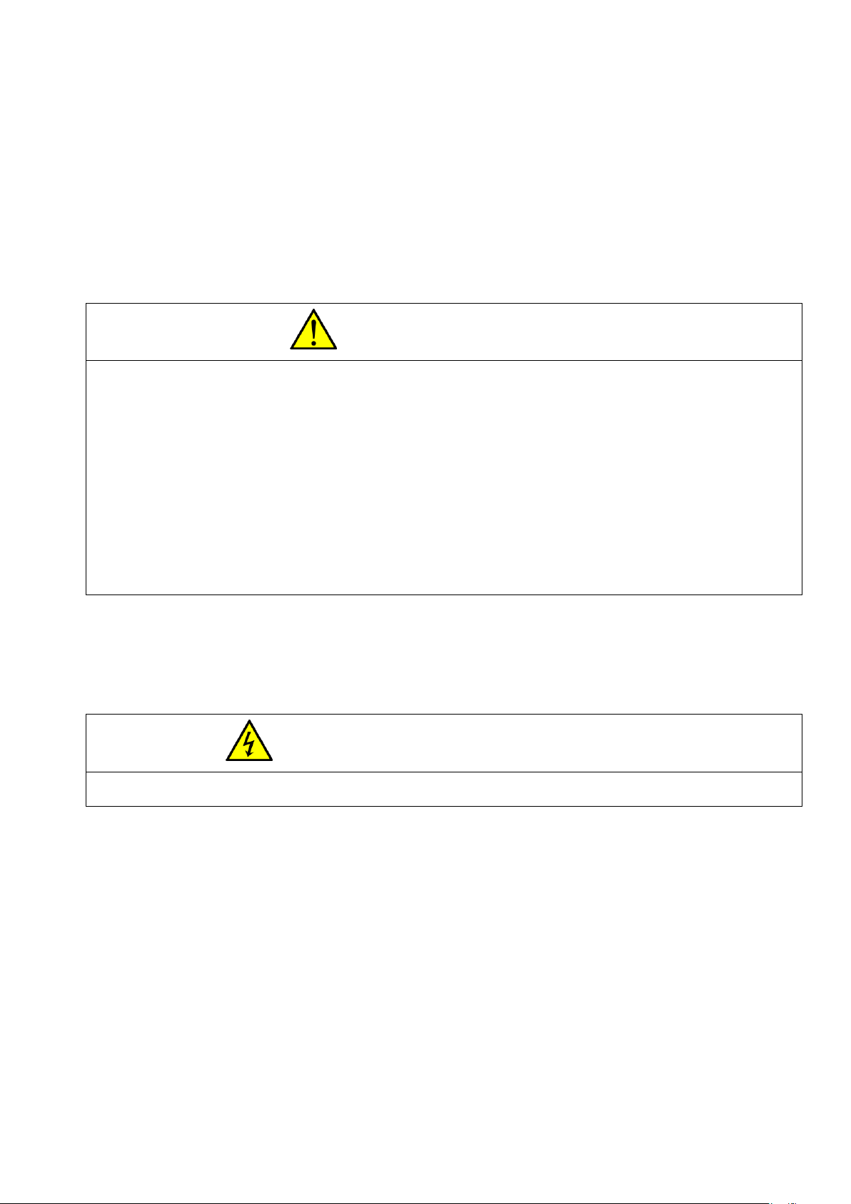
・ Installation orientation and intake/exhaust direction
Install the converter vertically with a cooling fan facing up. When it is installed sideways, ventilation is
prevented, which may increase temperature. You should sufficiently consider a path of intake and exhaust.
The cooling fan built in the converter sucks air from the bottom and exhausts it to the top. To prevent a wiring
duct, etc. from blocking up the vent, keep enough space.
・ Keeping cooling space
To install the converter, keep a cooling space.
When heat generation devices exist in the surrounding environment, place them so that they do not affect cooling
of the converter and others.
The operating temperatures of the converter are 0 to 50 ℃. To install it in the control board, perform ventilation
to ensure that the temperature in the board is below 50 ℃. High ambient temperature will decrease reliability.
16
3.2. How to Open and Close Front Cover
Warning Opening and closing front cover
● Be sure to turn off the converter when opening and closing the front cover.
Otherwise, it can result in a risk of electric shock.
3.2.1. How to Open Front Cover
To work inside the converter (such as connecting or wiring terminals, and maintenance/inspection), follow the
steps below to open the front cover.
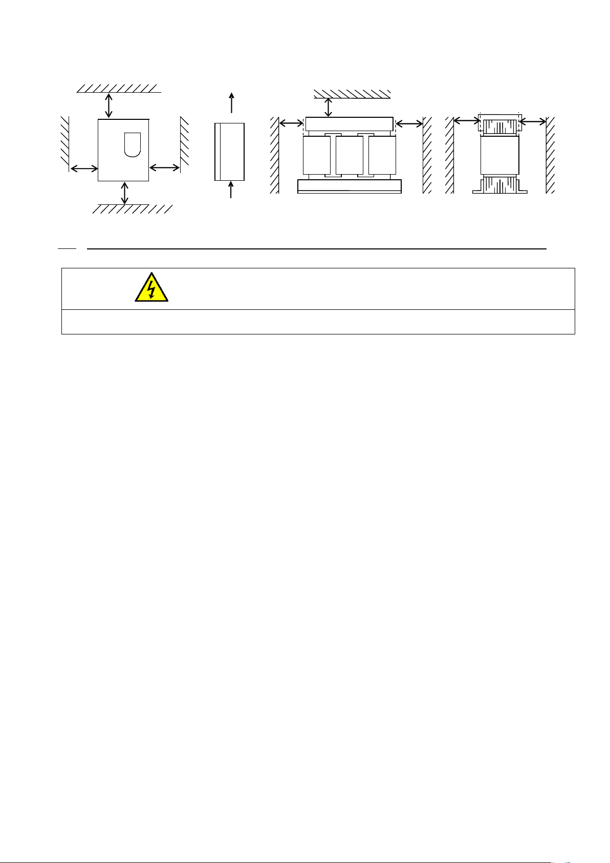
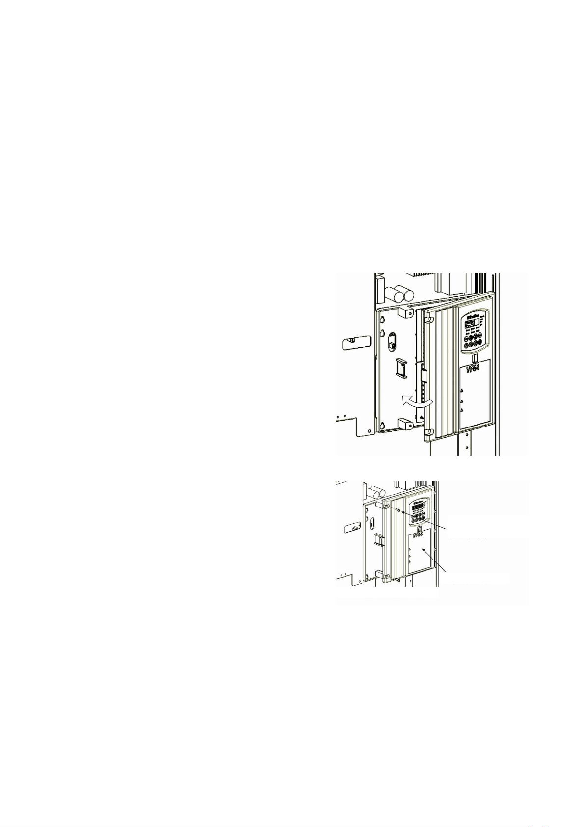
■ For models using a sheet-metal chassis and front cover
Remove the sheet-metal front cover and the resin control part cover.
1. Use the Phillips screwdriver (M4) to remove the mounting screws at the top of the front cover.
2. Loosen the screws at the bottom of it.
3. Remove the front cover from the main unit.
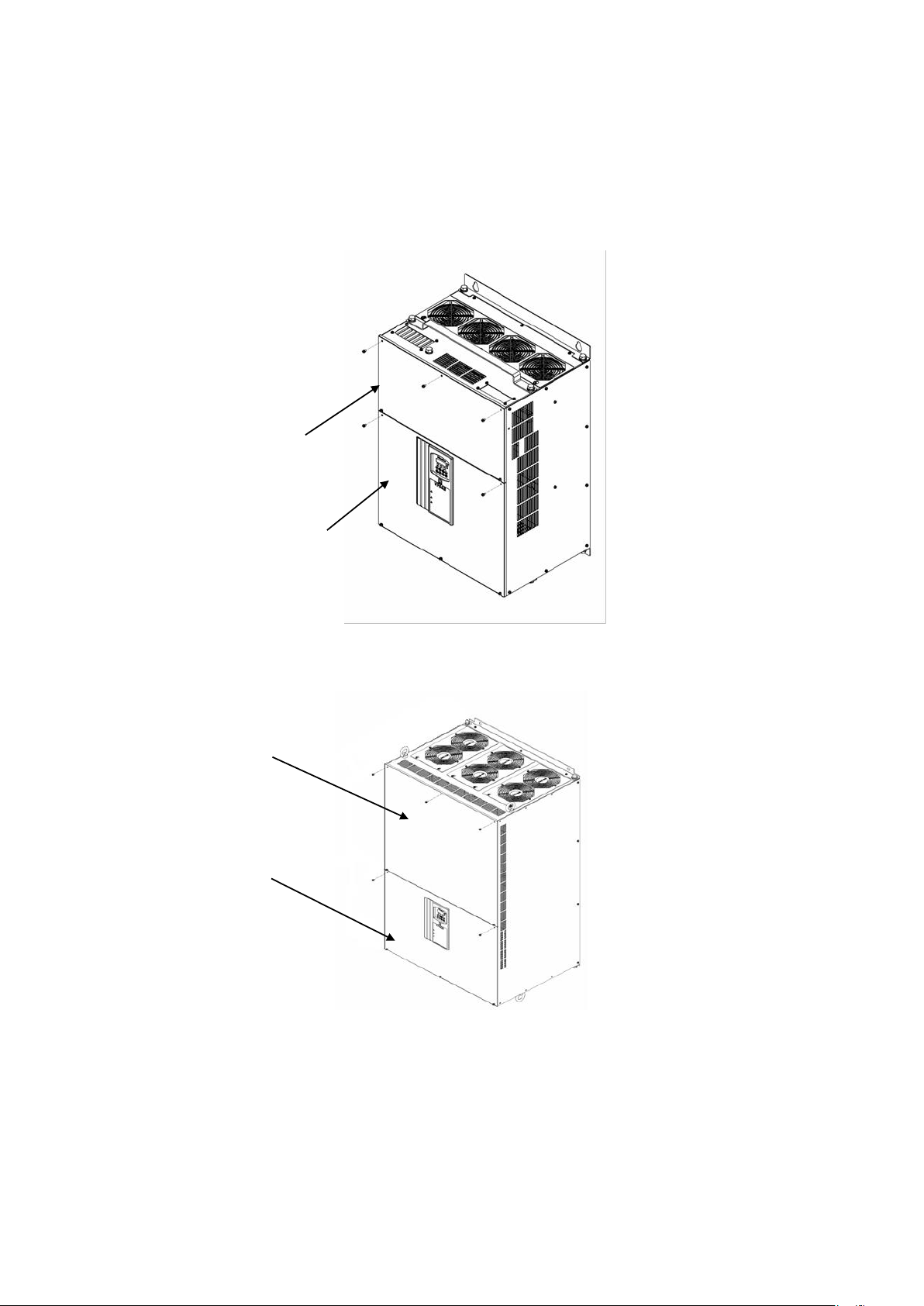
・ The number of mounting screws at the top and bottom of the front cover depends on the model. Refer to the
figure below.
30 cm or more
20 cm or more
10 cm or more
10 cm or more
Exhaust air
Intake air
Converter unit
15 cm or more
15 cm or more
15 cm or more
15 cm or more
20 cm or more
AC reactor
17
For VF66R-20044,25044,31544
(40044~100044)
Upper cover
For VF66R-7522,9022(15022,18022)
7544,11044,16044
Just loosen the lower screws to
remove the covers
Front cover mounting screw
(Upper cover: 5 pcs)
(Lower cover: 5 pcs)
Lower cover
Just loosen the lower screws to
remove the covers
Front cover mounting screw
(Upper cover: 5 pcs)
(Lower cover: 5 pcs)
4. When the control part cover is vibration resistant, use the
Phillips screwdriver (M4) to remove two mounting screws of the
control part cover.
・ When it is not vibration resistant, it does not have mounting
screws.
5. While holding the lock part of the control part cover with
your thumb, pull it and remove it,
using the two claws on the right side as supporting points.
Control part cover
mounting screw (2 pcs)
Control part cover
Claw
Lock part
<Vibration-resistant specification only>
18
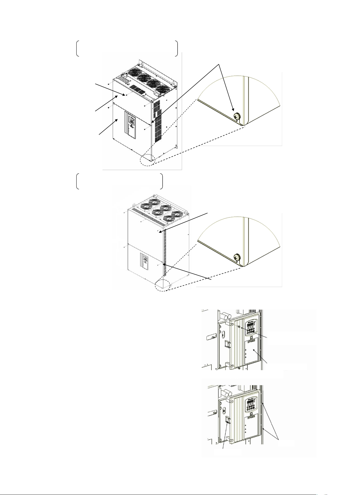
When opening the front cover, check that the serial number described in the front of the front cover matches
the one described inside the main unit.
<Front>
* Check that the serial number specified on the front cover agrees with
that specified inside the inverter.
Front cover
VFC66R-Z
Control board
7522
7522
69
75
Warning Notes for replacing parts
● Do not disassemble the converter unreasonably.
● After disassembling it, check that all parts are assembled correctly.
Incorrect assembly can result in a risk of a fire.
● In particular, if a flat cable is not inserted correctly, the control circuit may not work properly.
● Make sure that screws are tightened.
19
3.2.2. How to Close Front Cover
Follow the steps below to close the front cover of the converter.
When closing the front cover, ensure that the serial number described in the main unit matches the one described
on the front cover. For how to check the serial number, refer to {3.2.1. How to Open Front Cover}.
■ For models using a sheet-metal chassis and front cover
Install the resin control part cover and the sheet-metal front cover.
1. Insert the two claws on the right side of the control part cover into the sockets of the converter main
unit.
2. Push them until a lock clicks.
3. When the control part cover is vibration resistant, use the
Phillips screwdriver (M4) to tighten the two mounting screws of
the control part cover.
・ Tighten it within a tightening torque of 1.4 N・m.
・ When it is not vibration resistant, it does not have mounting
screws.
Control part cover
mounting screw (2 pcs)
<Vibration-resistant specification only>
Control part cover
20
4. Use the Phillips screwdriver (M4) to tighten the mounting screws of the front cover.
・ Tighten it within a tightening torque of 1.5 N・m.
・ The number of mounting screws of the front cover depends on the model. Refer to the figure below.
Upper cover
Lower cover
Mounting screw: Upper cover 5 pcs
Lower cover 5 pcs
VF66R-7522, 9022
7544, 11044, 16044
Mounting screw: Upper cover 4 pcs
Lower cover 4 pcs
VF66R-20044, 25044, 31544
Lower cover
Upper cover
21
3.3. How to Connect Converter
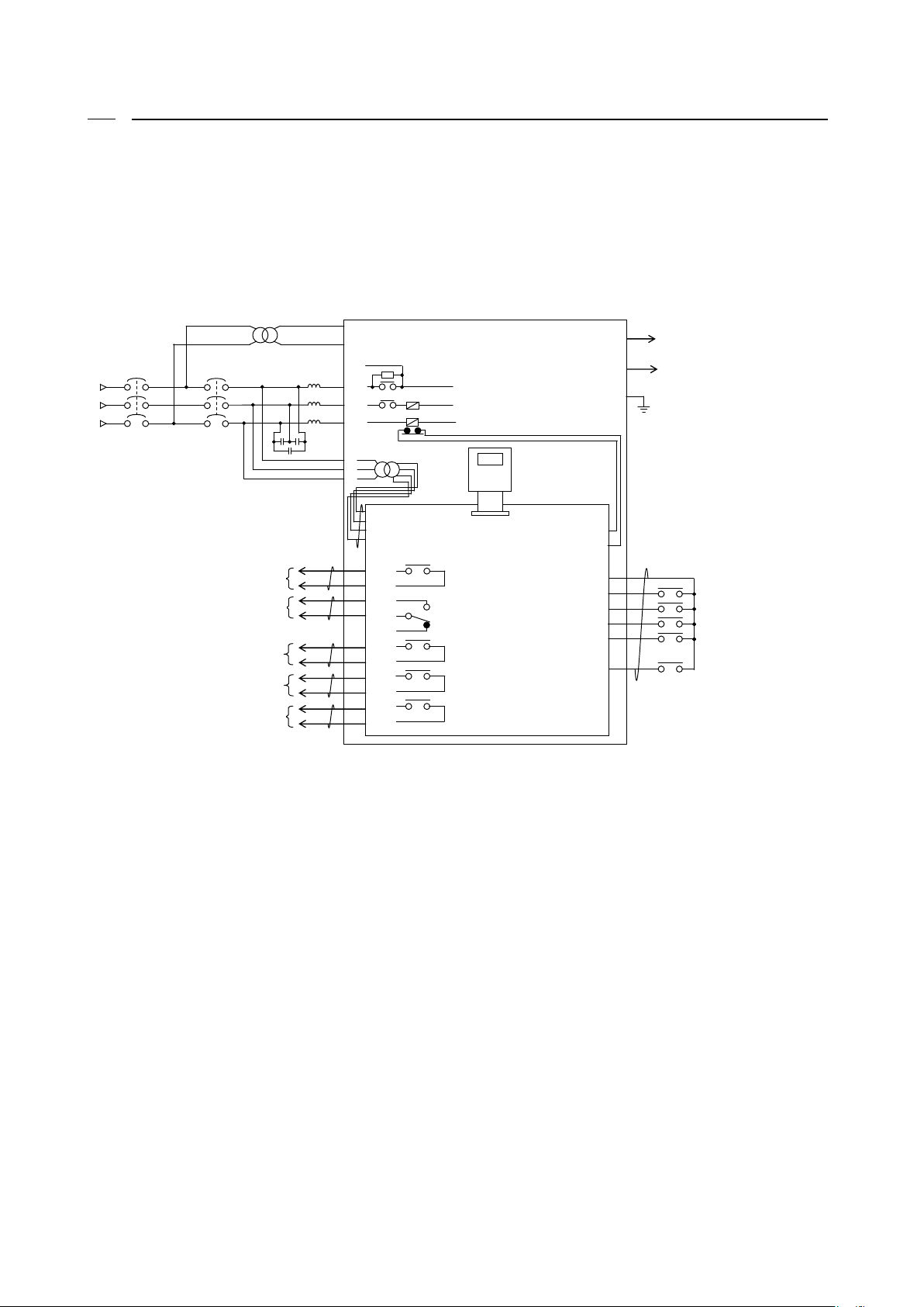
3.3.1. How to Connect Converter Terminals
The figure below shows the connection diagram of the converter (VF66R-7522,9022, and 7544 through 31544)
terminals.
For specifications of each terminal, refer to {3.4. Terminal Specifications}.
(1) Input the specified input voltage. Inputting 400 V to the 200 V class converter damages the unit and causes
a very dangerous situation.
(2) Be sure to connect MCCB of appropriate capacity to the main circuit input side.
(3) Be sure to connect the power supply line to RA, SA and TA. Connect so that the main circuit terminals [L1/R],
[L2/S] and [L3/T] correspond to RA, SA and TA, respectively.
(4) Be sure to connect to the ground terminal for safety reasons.
(5) To connect five or more inverters between the converter outputs of [+] and [-], you may need to connect
an adjustment resistor between the RR and R terminals. In this case, contact us.
(6) The AC power supply terminals [MR] and [MT] for the control circuit are not connected to the power supply
in normal situations. Connect them when the control circuit power needs to be turned on after turning off
the main circuit power. Be sure to insulate from the main circuits of [L1/R], [L2/S] and [L3/T] using a
transformer.
When the control power supply terminals [MR] and [MT] are used in parallel models (VF66R-15022, 18022,
and 40044 through 100044), power should be supplied to not only a master unit but a slave unit.
(7) The AC reactor used in the PWM sine wave mode is different from that used in the 120-degree conduction mode.
Be sure to use the AC reactors specified by Toyo Denki.
52MA
VFC66R-Z
TB1
GND
86A
CN2
SET66-Z
L1/R
L2/S
L3/T
-
+
運転
故障保護
運転(START)
多機能入力
PWM 正弦波コンバータモード
(予備)
非常停止(EX_F)
リセット(RESET)
MCCB
200~230V
380~460V
50/60Hz
TB1
4INC
4STA
4I
CN8
Fuse(+)
Fuse(-)
PS
START
MI5
MI4
MI1
MI2
MI3
インバータ運転可
4ATAa
4STAc
4Ic
4Ia
4INCa
4INCc
86Ab
86Ac
86Aa
52MAa
F
52M
絶縁トランス
RR
52MAc
RA
SA
TA
MR
MS
MT
1
2 3 4
VF66R
AC リアクトル
C
MC ON
MC ON 中
TB1
E
Insulation transformer
AC reactor
Failure protection
Inverter operation enable
During MC ON
AC fuse cut
DC output
Operation(START)
Reset(RESET)
Emergency stop(EX_F)
Multifunction input
(Unavailable)
PWM sine wave mode
Converter operation
MC ON
22
(8) A filter capacitor is required in the PWM sine wave mode. It is not used in the 120-degree conduction mode.
Be sure to use the filter capacitor specified by Toyo Denki.
(9) Never connect the GND and COM terminals of the control circuit to the ground terminal.
(10) In the factory default, the control input terminal [START] and multifunction input terminals [MI1] through
[MI5] are set to PS common input (source input). When changing them to GND common input (sync input), remove
a jumper socket on the control board <VFC66R-Z> from [CN-SO] and then attach it to [CN-SI].
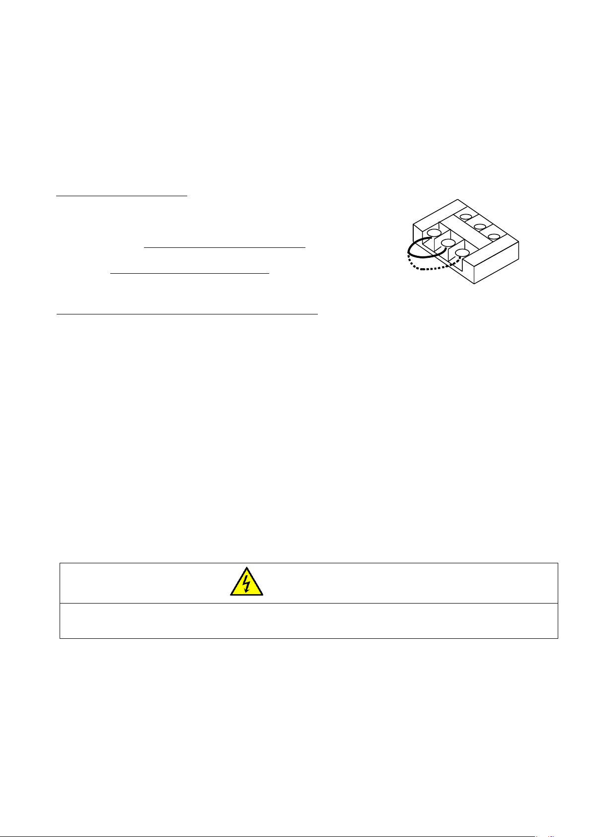
Changing a short-circuit wire
To use the VF66R-31544 or 16044 converter at a power supply voltage of 460 V,
you need to change a short-circuit wire.
* Notes for connecting multiple inverters to the converter
1. Up to five inverters can be connected to a single converter.
Be sure to select the converter having a rated capacity larger than the total capacity of inverters to
use.
For example, when total five 400 V class inverters of 11, 15, 22, 37 and 45 kW are used, the total capacity
is 130 kW and therefore VF66R-16044 should be selected.
Note that in using the PWM sine wave mode, the effect of suppressing distortion of power supply current
is decreased at a capacity half the converter rated capacity or less. In this case, it is possible to
use as a converter. To produce the harmonic suppression effect, however, it is recommended that the load
on the converter be more than half of the rated capacity.
2. To use the converter as a common converter for multiple inverters, connection of a resistor between the
terminals R and RR may be needed depending on the number of inverters to be connected.
For the resistance value and model, contact us.
Danger Wiring
● Never touch the terminals while the converter is energized. A voltage is applied to the converter output terminals even in
the stopped state.
Otherwise, it can result in a risk of electric shock.
RA1
MCA
RA
Power supply voltage used for the converter
・ 380 to 440 V: Short circuit between [MCA] and [RA] on the
terminal block shown on the right.
・ 460 V: Short circuit between [MCA] and [RA1] on the terminal
block shown on the right.

23
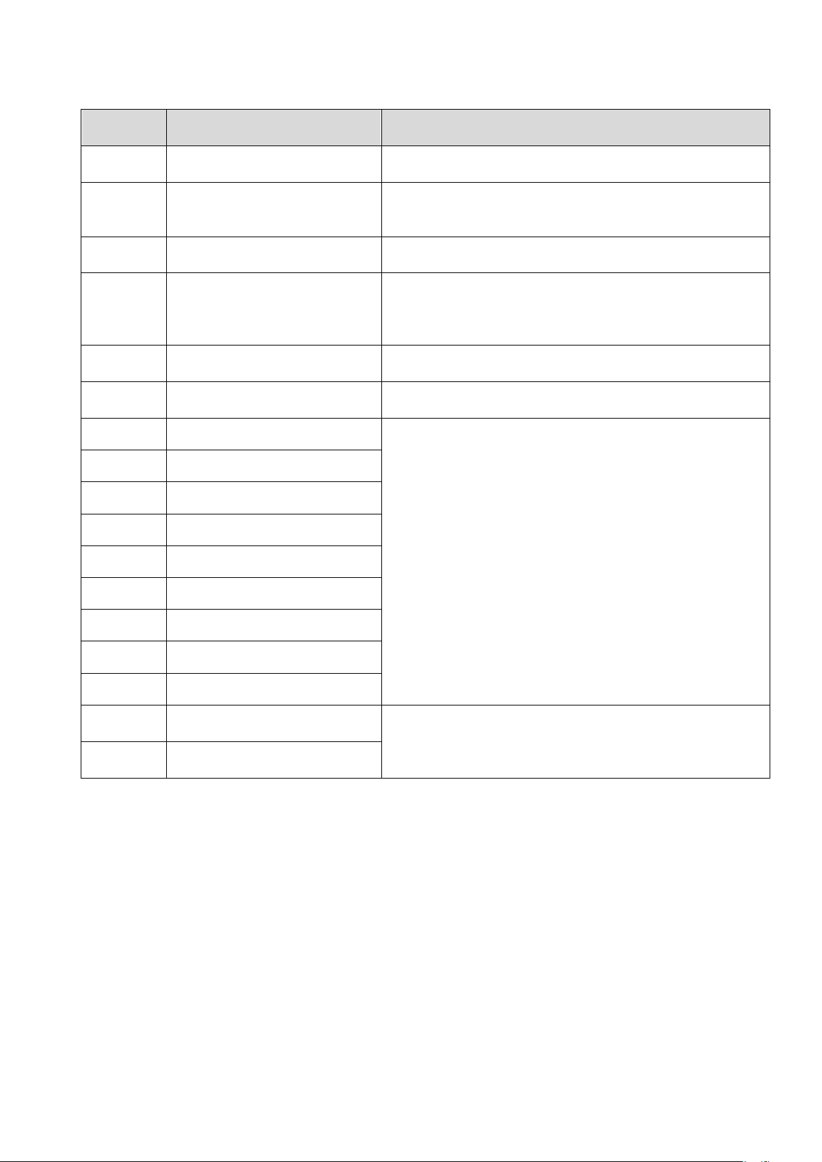
3.4. Terminal Specifications
Main circuit
Terminal
number
Purpose
Description
R/L1, S/L2,
T/L3
Spare
Unconnected
L1/R, L2/S,
L3/T
Converter input
・ PWM sine wave mode: Connected to the AC power supply through
the AC reactor for the PWM sine wave mode and filter capacitor.
・ 120-degree conduction mode: Connected to the AC power supply
through the AC reactor for the 120-degree conduction mode.
(Never input 400 V to the 200 V class converter.)
+, -
Converter DC output
Connect the DC input terminals of the inverter to be connected
to the converter.
Do not connect the power supply to the inverter terminals R/L1,
S/L2 and T/L3.
B
Spare
Unconnected
Ground terminal
[Caution] Be sure to connect it to the ground.
When using a noise filter, connect it to a ground terminal of
the filter.
MR, MS, MT
Control power supply terminal
・ Operation is available without connecting these terminals.
・ Used when power is supplied to the control circuit only.
・ Connect the AC power supply between [MR] and [MT], not [MS].
・ Connect to the main circuit through an insulation transformer.
[Caution] When used in parallel models (<15022>, <18022>, and
<40044> through <100044>), power should be supplied to not only
a master unit but a slave unit.
RA, SA, TA
Voltage detection
Connect the AC input power supply. Be sure to connect this
terminal.
Connect so that the converter main circuit terminals L1/R, L2/S
and L3/T correspond to RA, SA and TA, respectively.
A wrong connection causes malfunction of the converter.
24
Terminal block <TB1> on the control board <VFC66R-Z>
Terminal
number
Purpose
Description
52MA
Operation contact
Turns on while the converter is operated.
Contact rating 250 VAC, 30 VDC, 2 A
86A
Protection contact
86Aa-86Ac turns on and 86Ab-86Ac turns off while the converter
takes the protection operation.
Contact rating 250 VAC, 110 VDC, 0.3 A
4INC
External MC input permission
External MC input permission turns on.
Contact rating 250 VAC, 30 VDC, 2 A
4I
Inverter operation enable
Turns on when an inverter is permitted to run. Disable starting
an inverter while this relay is OFF, connecting this terminal
to the emergency stop (Normally closed), etc. of the inverter.
Contact rating 250 VAC, 30 VDC, 2 A
4STA
During MC ON
Turns on while the MC contact inside the converter unit is ON.
Contact rating 250 VAC, 30 VDC, 2 A
START
Operation signal
Input terminal for operation signal
PS
+12V output
Output +12 V DC voltage.
Multifunction input
・ Maximum input voltage 24 VDC, maximum input current 3 mA
■ Initial state (fixed functions)
・ Multifunction input terminal (1):
Multifunction input terminal
・ Multifunction input terminal (2):
Unused (internal PLC function available)
・ Multifunction input terminal (3):
Mode switch (ON: PWM OFF: 120-degree conduction)
・ Multifunction input terminal (4):
Emergency stop (Normally open)
・ Multifunction input terminal (5):
Protection reset
[Caution] Do not connect the terminal [GND] to the ground
terminal.
MI1
Multifunction input terminal (1)
PS
+12V output
MI2
Multifunction input terminal (2)
MI3
Multifunction input terminal (3)
MI4
Multifunction input terminal (4)
GND
GND terminal
MI5
Multifunction input terminal (5)
GND
GND terminal
FUSE(-)
Negative side input of
AC fuse
Detect a blown AC fuse.
FUSE(+)
Positive side input of
AC fuse
25
■ Terminal layout of main circuit terminals
● VF66R-7522 and 9022
VF66R-7544 through 16044
● VF66R-20044 through 31544
26
3.5. Notes for Wiring and Electrical Wire Size
3.5.1. Notes for Wiring
(1) Input the specified voltage into the converter terminals [L1/R], [L2/S], [L3/T], [+] and [-].
・ If you input the voltage specified for the 400 V class into the 200 V class converter,
the converter will be damaged.
・ If you input the voltage specified for the 200 V class into the 400 V class converter,
it may lead to malfunction or damage to the converter.
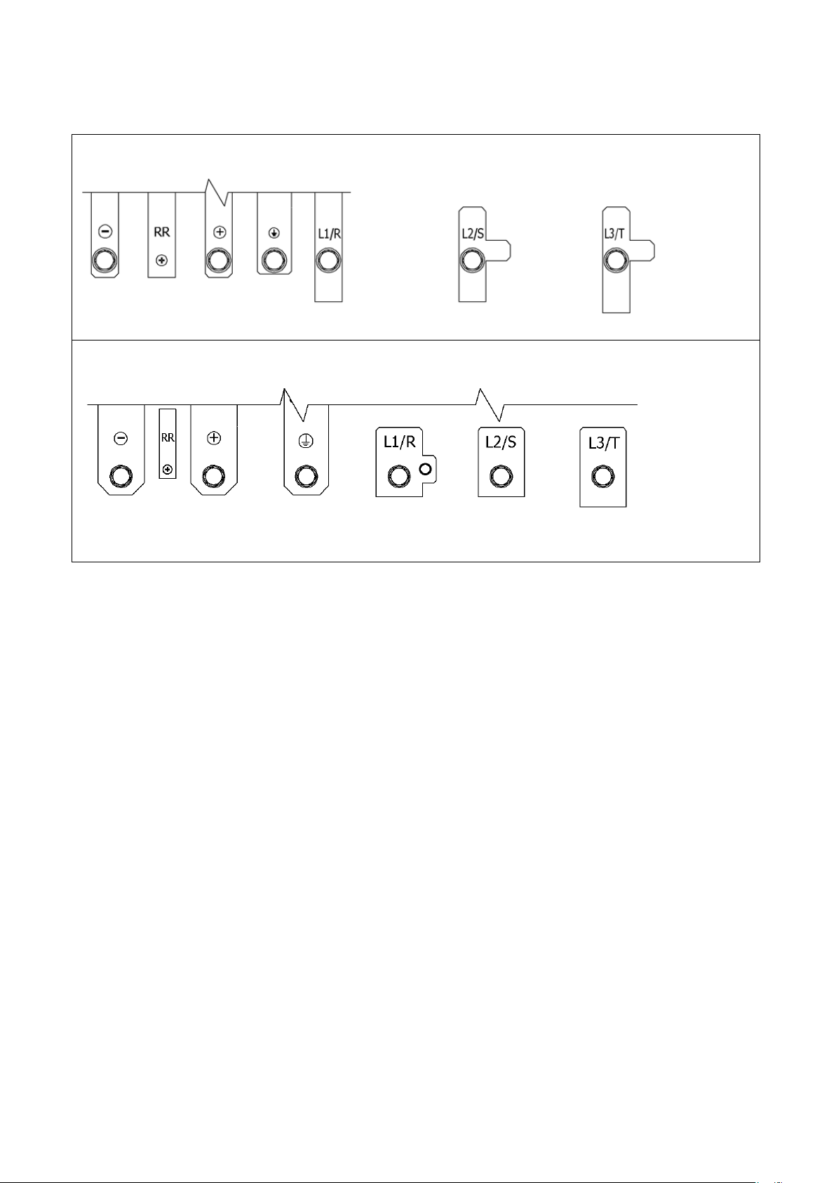
(2) IGBT is used in the converter, and the converter operates at a high frequency. Therefore, noise is emitted.
Consider the following points for wiring:
・ Keep main circuit wires away from a control signal wire. When placing them in parallel, keep a distance
of 30 cm or longer between them.
・ When crossing them, ensure that they are crossed at right angles.
・ It is recommended that the main circuit wire should be contained into a metal pipe as a measure against
noise for other facilities.
(3) To prevent noise contamination, use a shielded wire or a shielded twisted pair wire for the control signal
wire.
(4) When the wiring of the 400 V class converter is 100 m or longer in length
Due to the wiring, surge voltage may be generated in the device connected to the output terminal.
Take the following measure:
・ Connect a surge voltage suppression filter on the converter side.
Paralleled case
Intersected case
Control signal wire
30 cm or more
Control signal wire
Crossed at right angles
Main circuit
wires
Main circuit
wires

27
3.5.2. Electrical Wire Size of Input/Output Device and Main Circuit Wires
The electrical wire size of main circuit wires depends on the converter model.
See the table below to use appropriate electrical wires for connection.
■ 200 V class
Converter
model
Main circuit contactor
Wiring size [mm2]
(4)
Input MCCB
(2)
Input MC
(3)
Input side (AC)
Output side (DC)
Ground wire
(5)
Inside board
Outside
board
Inside board
Outside
board
VF66R-7522
400A
S-N400
150
150
150
150
22
VF66R-9022
400A
S-N400
150
150
200
200
38
VF66R-15022
800A - 150
150
150
150
22
VF66R-18022
800A - 150
150
200
200
38
■ 400 V class
Converter
model
Main circuit contactor
Wiring size [mm2]
(4)
Input MCCB
(2)
Input MC
(3)
Input side (AC)
Output side (DC)
Ground wire
(5)
Inside board
Outside
board
Inside board
Outside
board
VF66R-7544
200A
S-N200
60
60
60
60
14
VF66R-11044
300A
S-N300
80
80
100
100
22
VF66R-16044
400A
S-N400
150
150
200
200
22
VF66R-20044
500A
S-N600
200
200
200
200
38
VF66R-25044
600A
S-N600
250
250
150 x 2P
(8)
150 x 2P
(8)
38
VF66R-31544
700A
S-N800
150 x 2P
(8)
150 x 2P
(8)
150 x 2P
(8)
150 x 2P
(8)
50
VF66R-40044
1000A
-
200
200
200
200
38
VF66R-50044
1200A
-
250
150 x 2P
(8)
250
150 x 2P
(8)
38
VF66R-60044
1500A
-
200
200
200
200
38
VF66R-75044
2000A
-
250
150 x 2P
(8)
250
150 x 2P
(8)
38
VF66R-100044
2500A
-
250
150 x 2P
(8)
250
150 x 2P
(8)
38
(1) This table is based on the input voltage of 200 VAC for the 200 V class and 380 VAC for the 400 V class.
(2) Input MCCB indicates the rated current values. Determine the breaking capacity of MCCB based on the power
supply capacity, etc. Select a ground fault interrupter for the inverter.
(3) Input MC is selected based on the rated energizing current. Select an appropriate one as needed according
to the opening/closing frequency.
(4) Plan the wiring between the converter and power supply so that voltage drop is below 2 %. The table lists
wire size for inside the board (3 m in length as MLFC) and for outside the board (30 m in length as CV (three
single-core)).
(5) Use the ground wire with many element wires, such as KIV.
(6) Use the solderless terminal CB200-S12 manufactured by J.S.T. MFG. CO., LTD.
(7) Use the R type solderless terminal standardized by Japanese Industrial Standards (JIS C 2805) or the UL/cUL
approved round solderless terminal.
(8) Use "150-L12" for the solderless terminal.

28
3.5.3. Electrical Wire Size of Control Board
The electrical wire size of the terminal block TB1 on the control board <VFC66R-Z> is common to all converter
models.
Terminal block
Wiring size [mm2]
Terminal block TB1 on the control board <VFC66R-Z>
([52MA] - [FUSE(+)])
0.12 - 0.32
[AWG26 to 22]
29
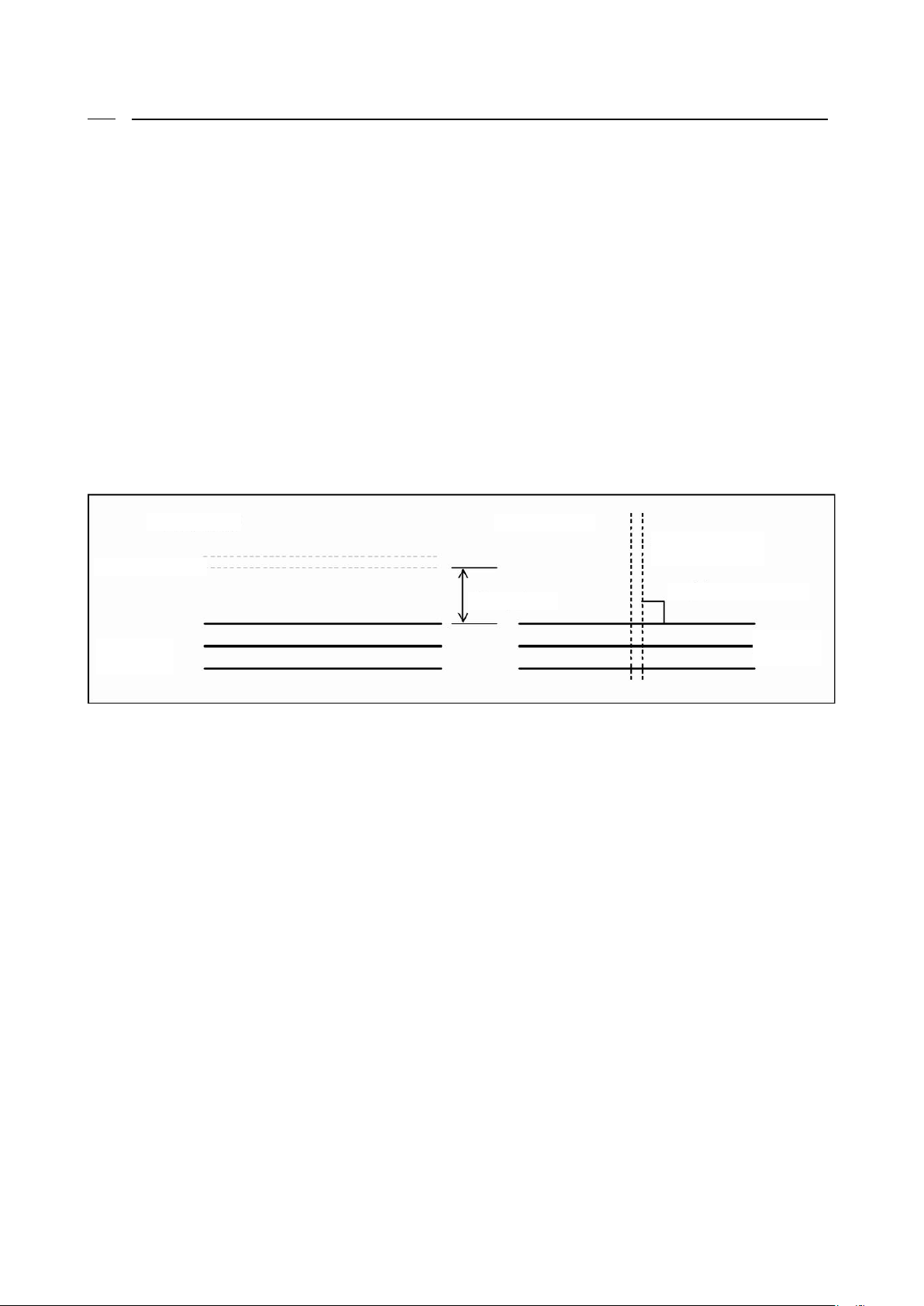
3.6. AC Filter
3.6.1. AC Reactor
The following tables show the AC reactors provided for the PWM sine wave mode.
For the AC reactors provided for the 120-degree conduction mode, contact us.
400V class
Converter model
AC reactor model
VF66R-7544
ACL7544
VF66R-11044
ACL11044
VF66R-16044
ACL16044
VF66R-20044
ACL20044
VF66R-25044
ACL25044
VF66R-31544
ACL31544
VF66R-40044
ACL20044 x 2
VF66R-50044
ACL25044 x 2
VF66R-60044
ACL20044 x 3
VF66R-75044
ACL25044 x 3
VF66R-100044
ACL25044 x 4
● Exterior and dimensions (reference)
Model
W H D
Weight Model
W H D
Weight
ACL7522
300
320
295
58
ACL7544
300
310
290
63
ACL9022
300
320
295
65
ACL11044
360
380
320
96
ACL16044
420
400
340
125
ACL20044
420
460
340
150
ACL25044
450
520
370
190
ACL31544
480
550
400
240
(Note) Units of dimension and weight are mm and kg, respectively.
200 V class
Converter model
AC reactor model
VF66R-7522
ACL7522
VF66R-9022
ACL9022
VF66R-15022
ACL7522 x 2
VF66R-18022
ACL9022 x 2
30
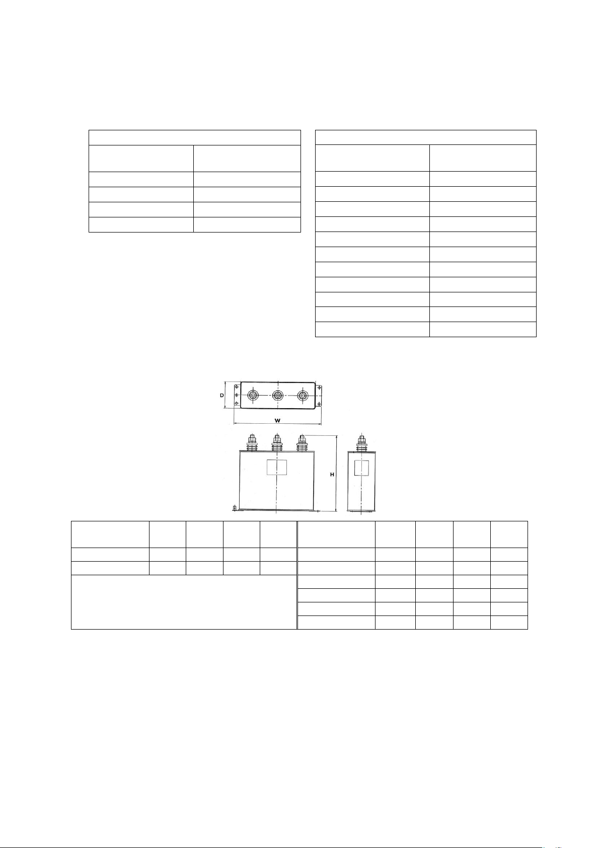
3.6.2. AC Filter Capacitor
The following tables show the AC filter capacitors provided for the PWM sine wave mode.
To use two or more capacitors arranged side by side, keep a space of at least 25 mm between adjacent capacitors.
AC filter capacitor is not used for the 120-degree conduction mode.
400 V class
Converter model
AC filter
capacitor model
VF66R-7544
QS24746-8R
VF66R-11044
QS24746-9R
VF66R-16044
QS24746-10R
VF66R-20044
QS24746-11R
VF66R-25044
QS24746-12R
VF66R-31544
QS24746-13R x 2
VF66R-40044
QS24746-11R x 2
VF66R-50044
QS24746-12R x 2
VF66R-60044
QS24746-11R x 3
VF66R-75044
QS24746-12R x 3
VF66R-100044
QS24746-12R x 4
● Exterior and dimensions (reference)
AC filter
capacitor model
W H D
Weight AC filter
capacitor model
W H D
Weight
QS24745-8R
280
260
90
6.0
QS24746-8R
280
210
90
4.5
QS24745-9R
280
260
90
6.0
QS24746-9R
280
260
90
5.5 QS24746-10R
280
290
90
6.5
QS24746-11R
435
350
100
15
QS24746-12R
435
350
100
15
QS24746-13R
280
290
90
6.5
(Note) Units of dimension and weight are mm and kg, respectively. AC reactors and AC filter capacitors need
to be resistant to switching ripple current.
Contact us for these items.
200 V class
Converter model
AC filter
capacitor model
VF66R-7522
QS24745-8R
VF66R-9022
QS24745-9R
VF66R-15022
QS24745-8R x 2
VF66R-18022
QS24745-9R x 2
 Loading...