

Page 1

TOYODA Machine Works, LTD.
TOYOPUC CMP-LINK
SIO Driver
1 System Configuration.......................................................................................................3
2 Selection of External Device ............................................................................................6
3 Example of Communication Setting.................................................................................7
4 Setup Items....................................................................................................................17
5 Cable Diagram...............................................................................................................22
6 Supported Device...........................................................................................................43
7 Device Code and Address Code....................................................................................47
8 Error Messages.......................................................... ....................................................50
1
Page 2
TOYOPUC CMP-LINK SIO Driver
Introduction
This manual describes how to connect the Display and the External Device (target PLC).
In this manual, the connection procedure will be described by following the below sections:
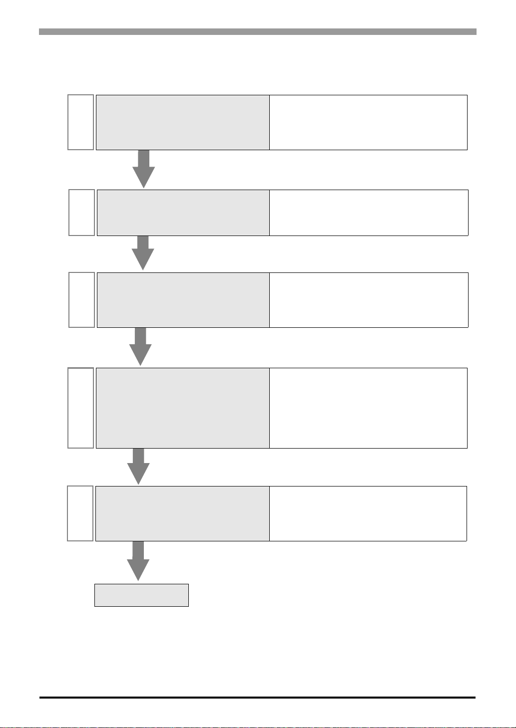
System Configuration
1
This section shows the types of External
Devices which can be connected and SIO
type.
Selection of External Device
2
Select a model (series) of External Device
to be connected and connection method.
Example of Communication Settings
3
This section shows setting examples for
communicating between the Display and
the External Device.
) "1 System Configuration" (page 3)
) "2 Selection of External Device" (page 6)
) "3 Example of Communication Setting" (page
7)
Communication Settings
4
Perform the communication settings
between the Display and the External
Device.
Set communication settings of the Display
with GP-Pro EX or in off-line mode.
Cable Diagram
5
This section shows cables and adapters
for connecting the Display and the
External Device.
Operation
) "4 Setup Items" (page 17)
) "5 Cable Diagram" (page 22)
GP-Pro EX Device/PLC Connection Manual
2
Page 3
TOYOPUC CMP-LINK SIO Driver
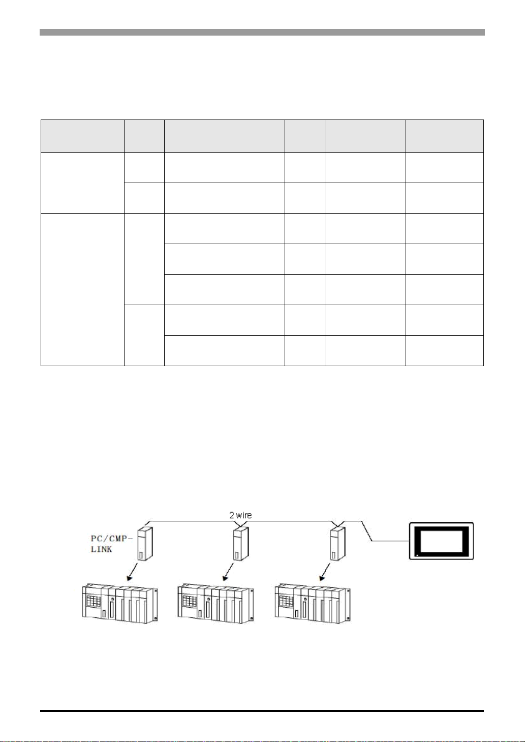
1 System Configuration
The system configuration in the case when the External Device of TOYODA Machine Works, LTD. and the
Display are connected is shown.
Series CPU Link I/F
PC2
L2
TOYOPUC-PC2
PC2J THU-2755 (PC/CMP-LINK)
PC3J
TOYOPUC-PC3J
PC3JD
PC3JG
*1 When using PC/CMP-LINK (THU-2755) with PC3J command, the link unit in ver. 5.00 or higher is required.
Also, the link unit does not have the settings of PC2J or PC3J selection switch (SW) etc. Error occurs when
sending PC3J command to the link unit in less than ver. 5.00.
THU-2652
(computer link module)
Link I/F on the CPU unit
(L2 terminal block)
Link I/F on the CPU unit
(L1, L2 terminal block)
THU-2755 (PC/CMP-LINK)
Link I/F on the CPU unit
(L1 terminal block)
THU-2755
(PC/CMP-LINK)
*1
SIO
Type
RS422
(2wire)
RS422
(2wire)
RS422
(2wire)
RS422
(4wire)
RS422
(2wire)
RS422
(2wire)
RS422
(2wire)
Setting Example Cable Diagram
Setting Example 1
(page 7)
Setting Example 2
(page 9)
Setting Example 3
(page 11)
Setting Example 4
(page 13)
Setting Example 5
(page 15)
Setting Example 3
(page 11)
Setting Example 5
(page 15)
Cable Diagram 1
(page 22)
Cable Diagram 1
(page 22)
Cable Diagram 2
(page 28)
Cable Diagram 3
(page 34)
Cable Diagram 4
(page 38)
Cable Diagram 1
(page 22)
Cable Diagram 1
(page 22)
Connection Configuration
The system configuration in the case when you use the External Device PC2J (n units) of TOYODA Machine
Works, LTD. and the GP (1 unit) to realize the 1:n communication with HOST link protocol are connected is
shown.
• Always set one unit of the Display used in the system.
• On the link, you can connect max 16 units of the External Device to one unit of the Display.
GP-Pro EX Device/PLC Connection Manual
3
Page 4

TOYOPUC CMP-LINK SIO Driver
COM Port of IPC
When connecting IPC with External Device, the COM port which can be used changes with series and SIO type.
Please refer to the manual of IPC for details.
Usable port
Series
Usable port
RS-232C RS-422/485(4 wire) RS-422/485(2 wire)
*1
PS-2000B
COM1
COM3
PS-3650A, PS-3651A COM1
PS-3700A (Pentium®4-M)
PS-3710A
COM1
COM3
PS-3711A COM1*1, COM2
, COM2,
*1
, COM4
*1
*1
, COM2*1,
*2
, COM4
--
--
*2
COM3
*2
COM2
*2
COM3
COM2
*2
*2
*1 The RI/5V can be switched. Please switch with the change switch of IPC.
*2 It is necessary to set up the SIO type with the Dip switch. Please set up as follows according to SIO
type to be used.
Dip switch setting: RS-232C
Dip switch Setting Description
1 OFF Reserve (always OFF)
2OFF
SIO type: RS-232C
3OFF
4 OFF Output mode of SD (TXD) data: Always output
5 OFF Terminal resistance (220Ω) insertion to SD (TXD): None
6 OFF Terminal resistance (220Ω) insertion to RD (RXD): None
7 OFF Short-circuit of SDA (TXA) and RDA (RXA): Does not Exist
8 OFF Short-circuit of SDB (TXB) and RDB (RXB): Does not Exist
9OFF
10 OFF
GP-Pro EX Device/PLC Connection Manual
RS (RTS) Auto control mode: Disable
4
Page 5
Dip switch setting: RS-422/485 (4 wire)
Dip switch Setting Description
1 OFF Reserve (always OFF)
2ON
3ON
4 OFF Output mode of SD (TXD) data: Always output
5 OFF Terminal resistance (220Ω) insertion to SD (TXD): None
6 OFF Terminal resistance (220Ω) insertion to RD (RXD): None
7 OFF Short-circuit of SDA (TXA) and RDA (RXA): Does not Exist
8 OFF Short-circuit of SDB (TXB) and RDB (RXB): Does not Exist
9OFF
10 OFF
Dip switch setting: RS-422/485 (2 wire)
Dip switch Setting Description
1 OFF Reserve (always OFF)
2ON
3ON
4 OFF Output mode of SD (TXD) data: Always output
5 OFF Terminal resistance (220Ω) insertion to SD (TXD): None
TOYOPUC CMP-LINK SIO Driver
SIO type: RS-422/485
RS (RTS) Auto control mode: Disable
SIO type: RS-422/485
6 OFF Terminal resistance (220Ω) insertion to RD (RXD): None
7 ON Short-circuit of SDA (TXA) and RDA (RXA): Exist
8 ON Short-circuit of SDB (TXB) and RDB (RXB): Exist
9ON
10 ON
RS (RTS) Auto control mode : Enable
GP-Pro EX Device/PLC Connection Manual
5
Page 6
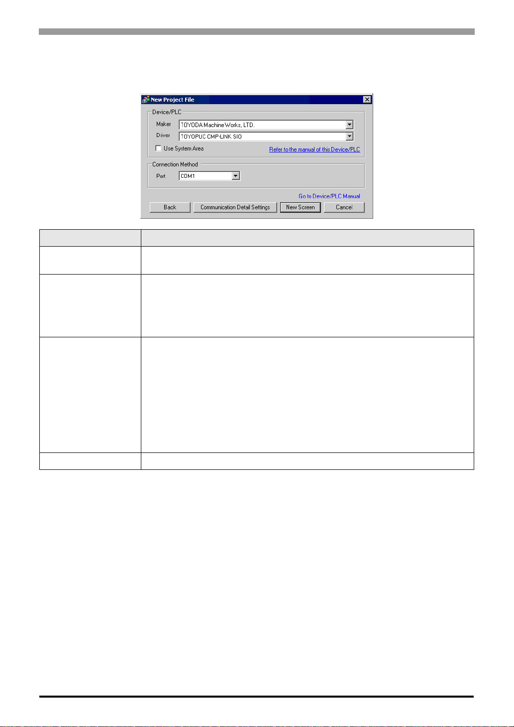
2 Selection of External Device
Select the External Device to be connected to the Display.
Setup Items Setup Description
TOYOPUC CMP-LINK SIO Driver
Maker
Driver
Select the maker of the External Device to be connected. Select "TOYODA Machine
Works, LTD.".
Select a model (series) of the External Device to be connected and connection method.
Select "TOYOPUC CMP-LINK SIO".
Check the External Device which can be connected in "TOYOPUC CMP-LINK SIO" in
system configuration.
)"1 System Configuration" (page 3)
Check this option when you synchronize the system data area of the Display and th e device
(memory) of the External Device. When synchronized, you can use the ladder program of
the External Device to switch the display or display the window on the Display.
Cf. GP-Pro EX Reference Manual "Appendix 1.4 LS Area (only for direct
Use System Area
Port Select the Display port to be connected to the External Device.
access method)"
This can be also set with GP-Pro EX or in off-line mode of the Display.
Cf. GP-Pro EX Reference Manual "System Area Setting, 5.14.6 Setting Guide
of [System Setting Window]"
Cf. Maintenance/Troubleshooting "2.14.1 Settings common to all Display
modelsSystem Area Settings"
GP-Pro EX Device/PLC Connection Manual
6
Page 7
TOYOPUC CMP-LINK SIO Driver
3 Example of Communication Setting
Examples of communication settings of the Display and the External Device, recommended by Pro-face, are
shown.
When you use the FX Series, use GP-Pro EX and the ladder software to set as below.
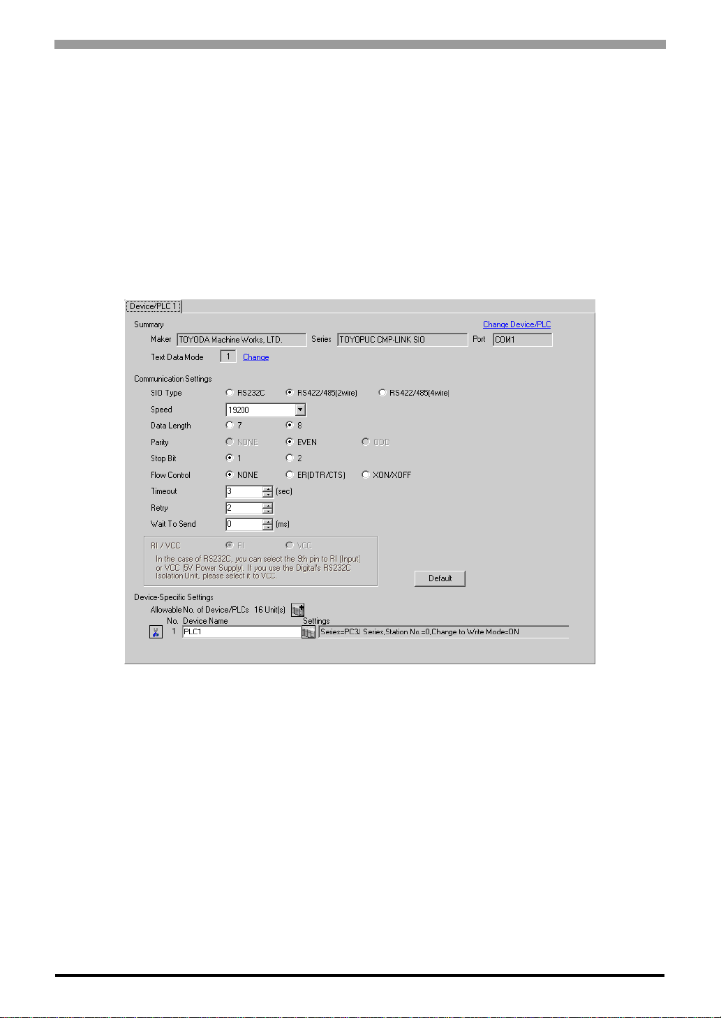
3.1 Setting Example 1
Setting of GP-Pro EX
Communication Settings
To display the setting screen, select [Device/PLC Settings] from [System setting window] in workspace.
GP-Pro EX Device/PLC Connection Manual
7
Page 8
TOYOPUC CMP-LINK SIO Driver
Device Setting
To display the setting screen, click ([Setting]) of External Device you want to set from [Device-Specific
Settings] of [Device/PLC Settings].
When you connect multiple External Device, click from [Device-Specific Settings] of [Device/PLC
Settings] to add another External Device.
Setting of External Device
Set the computer link module as below.
Please refer to the manual of the External Device for more details on settings.
Setup Items Settings
Speed 19200bps
Data Bit 8bit
Stop Bit 1bit
Parity Bit Even
Card Type CMP link
SET5 Watchdog timer ON
Station No. 0
GP-Pro EX Device/PLC Connection Manual
8
Page 9
TOYOPUC CMP-LINK SIO Driver
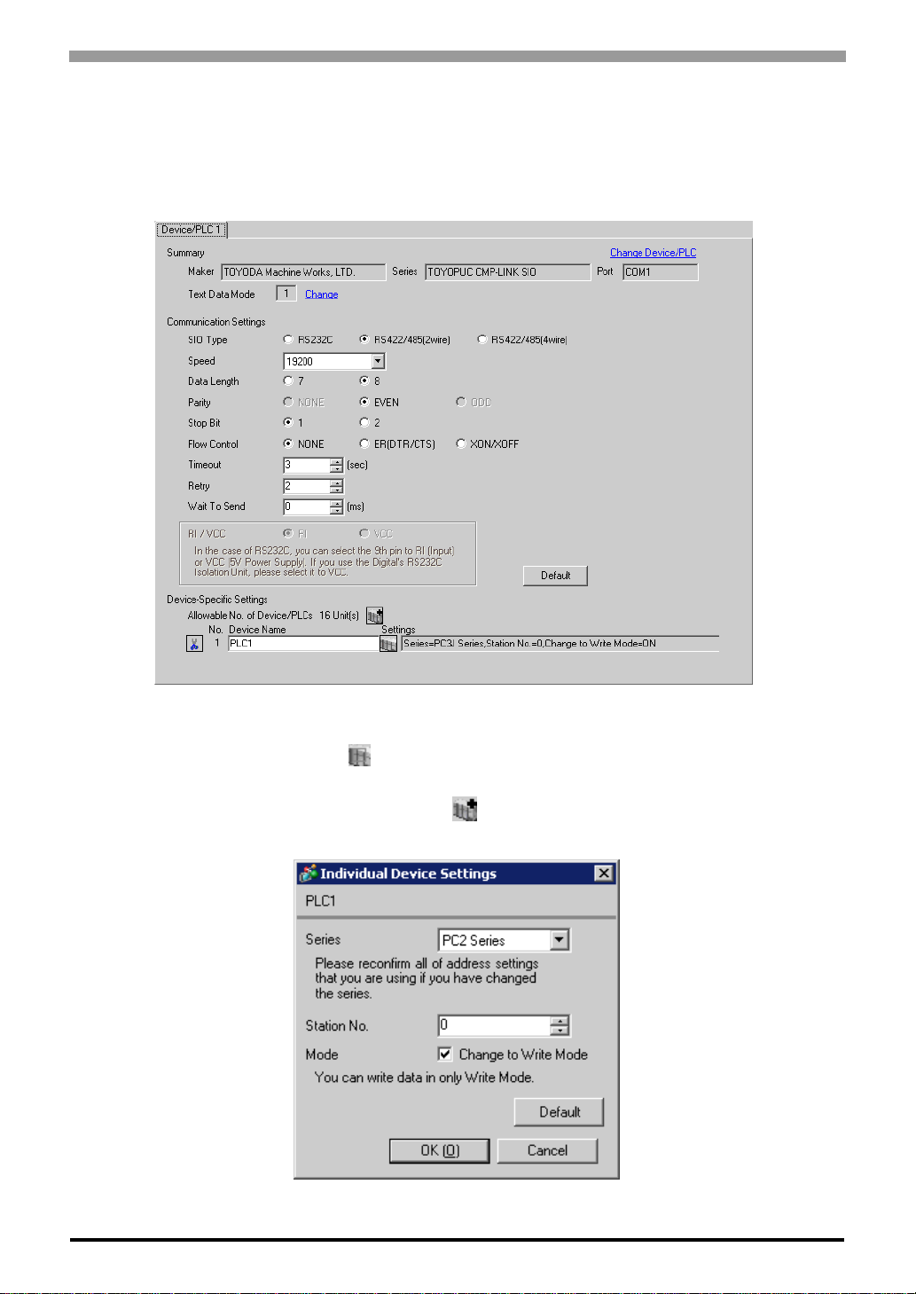
3.2 Setting Example 2
Setting of GP-Pro EX
Communication Settings
To display the setting screen, select [Device/PLC Settings] from [System setting window] in workspace.
Device Setting
To display the setting screen, click ([Setting]) of External Device you want to set from [Device-Specific
Settings] of [Device/PLC Settings].
When you connect multiple External Device, click from [Device-Specific Settings] of [Device/PLC
Settings] to add another External Device.
GP-Pro EX Device/PLC Connection Manual
9
Page 10

Setting of External Device
Set the computer link module as below.
Please refer to the manual of the External Device for more details on settings.
Setup Items Settings
Speed 19200bps
Data Bit 8bit
Stop Bit 1bit
Parity Bit Even
TOYOPUC CMP-LINK SIO Driver
Internal Switch
Station No. 1
SW4-1 OFF
SW4-2 ON
GP-Pro EX Device/PLC Connection Manual
10
Page 11
TOYOPUC CMP-LINK SIO Driver
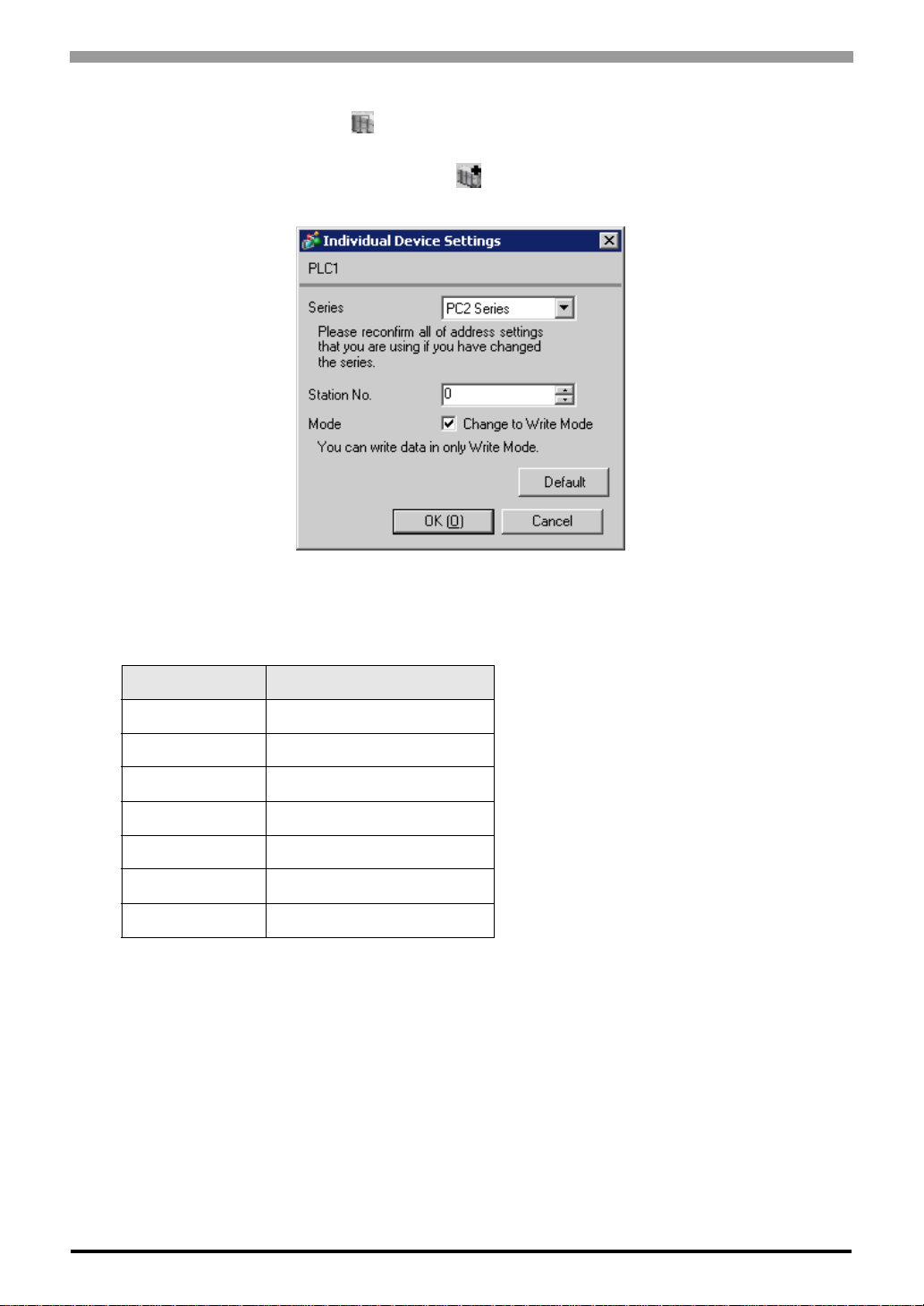
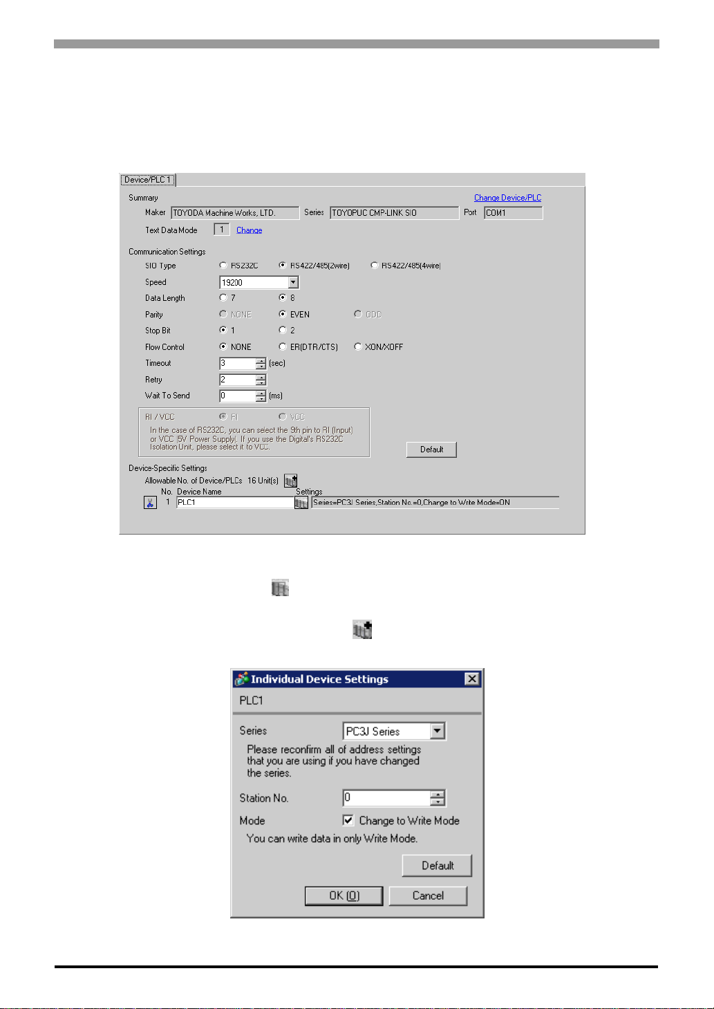
3.3 Setting Example 3
Setting of GP-Pro EX
Communication Settings
To display the setting screen, select [Device/PLC Settings] from [System setting window] in workspace.
Device Setting
To display the setting screen, click ([Setting]) of External Device you want to set from [Device-Specific
Settings] of [Device/PLC Settings].
When you connect multiple External Device, click from [Device-Specific Settings] of [Device/PLC
Settings] to add another External Device.
GP-Pro EX Device/PLC Connection Manual
11
Page 12
Setting of External Device
Set the computer link module as below.
Please refer to the manual of the External Device for more details on settings.
Setup Items Settings
Speed 19200bps
Data Bit 8bit
Stop Bit 1bit
Parity Bit Even
TOYOPUC CMP-LINK SIO Driver
RS422
Connecting Port
STATION No. 0
2wire
GP-Pro EX Device/PLC Connection Manual
12
Page 13
TOYOPUC CMP-LINK SIO Driver
3.4 Setting Example 4
Setting of GP-Pro EX
Communication Settings
To display the setting screen, select [Device/PLC Settings] from [System setting window] in workspace.
Device Setting
To display the setting screen, click ([Setting]) of External Device you want to set from [Device-Specific
Settings] of [Device/PLC Settings].
When you connect multiple External Device, click from [Device-Specific Settings] of [Device/PLC
Settings] to add another External Device.
GP-Pro EX Device/PLC Connection Manual
13
Page 14

Setting of External Device
Set the computer link module as below.
Please refer to the manual of the External Device for more details on settings.
Setup Items Settings
Speed 19200bps
Data Bit 8bit
Stop Bit 1bit
Parity Bit Even
TOYOPUC CMP-LINK SIO Driver
RS422
Connecting Port
STATION No. 0
4wire
GP-Pro EX Device/PLC Connection Manual
14
Page 15
TOYOPUC CMP-LINK SIO Driver
3.5 Setting Example 5
Setting of GP-Pro EX
Communication Settings
To display the setting screen, select [Device/PLC Settings] from [System setting window] in workspace.
Device Setting
To display the setting screen, click ([Setting]) of External Device you want to set from [Device-Specific
Settings] of [Device/PLC Settings].
When you connect multiple External Device, click from [Device-Specific Settings] of [Device/PLC
Settings] to add another External Device.
GP-Pro EX Device/PLC Connection Manual
15
Page 16

Setting of External Device
Set the computer link module as below.
Please refer to the manual of the External Device for more details on settings.
Setup Items Settings
Speed 19200bps
Data Bit 8bit
Stop Bit 1bit
Parity Bit Even
RS422
Connecting
*1
Port
STATION No. 0
*1 When using PC/CMP-LINK (THU-2755),
only 2-wire type is available to use. In addition,
when using PC3J command, the link unit in
ver. 5.00 or higher is required.
2wire
TOYOPUC CMP-LINK SIO Driver
GP-Pro EX Device/PLC Connection Manual
16
Page 17

TOYOPUC CMP-LINK SIO Driver
4 Setup Items
Set communication settings of the Display with GP-Pro EX or in off-line mode of the Display.
The setting of each parameter must be identical to that of External Devic e.
)"3 Example of Communication Setting" (page 7)
4.1 Setup Items in GP-Pro EX Communication Settings
To display the setting screen, select [Device/PLC Settings] from [System setting window] in workspace.
Setup Items Setup Description
SIO Type Select the SIO type to communicate with the External Device.
Speed Select speed between the External Device and the Display.
Data Length Select data length.
Parity Select how to check parity.
Stop Bit Select stop bit length.
Flow Control
Timeout
Retry
Wait To Send
RI/VCC
Select the communication control method to prevent overflow of transmission and
reception data.
Use an integer from 1 to 127 to enter the time (s) for which the Display waits for the
response from the External Device.
In case of no response from the External Device, use an integer from 0 to 255 to enter how
many times the Display retransmits the command.
Use an integer from 0 to 255 to enter standby time (ms) for the Display from receiving
packets to transmitting next commands.
You can switch RI/VCC of the 9th pin when you select RS232C for SIO type.
It is necessary to change RI/5V by changeover switch of IPC when connect with IPC.
Please refer to the manual of the IPC for more detail.
GP-Pro EX Device/PLC Connection Manual
17
Page 18

TOYOPUC CMP-LINK SIO Driver
Device Setting
To display the setting screen, click ([Setting]) of the External Device you want to set from [Device-Specific
Settings] of [Device/PLC Settings].
When [Allowable No. of Device/PLCs] is multiple, you can click from [Device-Specific Settings] of [Device/
PLC Settings] to add the External Device which is available to set.
Setup Items Setup Description
Series Select either " PC3J Series" or "PC2 Series" for the driver series name.
Station No. Use an integer from 0 to 31 (octal) to enter th e station No.
Mode
When receiving write request from GP-Pro EX, check "ON" to change the External Device
to the write mode.
• The External Device does not receive write from the Display in operation mode. When the
"operation mode" is enabled, the External Device will be changed to the monitor mode at
startup, which allows you to write to the External Device.
GP-Pro EX Device/PLC Connection Manual
18
Page 19

TOYOPUC CMP-LINK SIO Driver
4.2 Setup Items in Off-Line Mode
• Please refer to Maintenance/Troubleshooting for more information on how to enter off-line mode
or about operation.
Cf. Maintenance/Troubleshooting "2.2 Offline Mode"
Communication Settings
To disp lay the setting screen, touch [Dev ice/ PLC Sett ings] from [Peri pheral Set tings] i n the off-line mode. Touch
the External Device you want to set from the displayed list.
Setup Items Setup Description
Select the SIO type to communicate with the External Device.
SIO Type
Speed Select speed between the External Device and the Display.
Data Length Select data length.
Parity Select how to check parity.
Stop Bit Select stop bit length.
Flow Control
Timeout
Retry
Wait To Send
To make the communication settings correctly, confirm the serial interface specifications of
Display unit for [SIO Type].
We cannot guarantee the operation if a communication type that the serial interface does not
support is specified.
For details concerning the serial interface specifications, refer to the manual for Display unit.
Select the communication control method to prevent overflow of transmission and reception
data.
Use an integer from 1 to 127 to enter the time (s) for which the Display waits for the response
from the External Device.
In case of no response from the External Device, use an integer from 0 to 255 to enter how many
times the Display retransmits the command.
Use an integer from 0 to 255 to enter standby time (ms) for the Display from receiving packets to
transmitting next commands.
GP-Pro EX Device/PLC Connection Manual
19
Page 20

TOYOPUC CMP-LINK SIO Driver
Device Setting
To disp lay the setting screen, touch [Dev ice/ PLC Sett ings] from [Peri pheral Set tings] i n the off-line mode. Touch
the External Device you want to set from the displayed list, and touch [Device].
Setup Items Setup Description
Device/PLC Name
Series Displays the series name of the External Device.
Station No. Use an integer from 0 to 31 (octal) to enter th e station No.
Write Command
Select the External Device for device setting. Device name is a title of External Device set
with GP-Pro EX.(Initial value [PLC1])
When receiving write request from GP-Pro EX, check "ON" to change the External Device
to the write mode.
GP-Pro EX Device/PLC Connection Manual
20
Page 21

TOYOPUC CMP-LINK SIO Driver
Option
To disp lay the settin g screen, touch [De vic e/PL C Sett ings] from [Pe riph eral Sett ings]. Touch the External Device
you want to set from the displayed list, and touch [Option].
GP-Pro EX Device/PLC Connection Manual
21
Page 22

TOYOPUC CMP-LINK SIO Driver
5 Cable Diagram
The cable diagram shown below may be different from the cable diagram recommended by TOYODA Machine
Works, Ltd. Please be assured there is no operational problem in applying the cable diagram shown in this
manual.
• The FG pin of the main body of the External Device must be D-class grounded. Please refer to the manual of
the External Device for more details.
• SG and FG are connected inside the Display. When connecting SG to the External Device, design the system
not to form short-circuit loop.
• Use the double shield connection cable.
• Connect the isolation unit, when communication is not stabilized under the influence of a noise etc.
Cable Diagram 1
Display
(Connection Port)
*1
GP
(COM1)
AGP-3302B (COM2)
*2
(COM2)
ST
*3
GP
(COM2)
*4
IPC
Cable Remarks
COM port conversion adapter by Pro-face
CA3-ADPCOM-01
A
B Your own cable
C
D
E
Te rminal block conversion adapter
CA3-ADPTRM-01
Online adapter by Pro-face
CA4-ADPONL-01
Te rminal block conversion adapter
CA3-ADPTRM-01
Online adapter by Pro-face
CA4-ADPONL-01
COM port conversion adapter by Pro-face
CA3-ADPCOM-01
Te rminal block conversion adapter
CA3-ADPTRM-01
+
by Pro-face
+
Your own cable
+
by Pro-face
+
Your own cable
+
Your own cable
+
by Pro-face
+
Your own cable
The cable length must
be 500m or less.
The cable length must
be 500m or less.
The cable length must
be 500m or less.
F Your own cable
*1 All GP models except AGP-3302B
*2 All ST models except AST-3211A
*3 All GP models except GP-3200 series and AGP-3302B
GP-Pro EX Device/PLC Connection Manual
22
Page 23

TOYOPUC CMP-LINK SIO Driver
*4 Only the COM port which can communicate by RS-422/485 (2 wire) can be used.
) COM Port of IPC (page 4)
• For connection cable, we recommend the double shield 0-VCTF-SS 2C*0.75mm2 by Chugoku
Electric Wire & Cable Co., Ltd., the double shield UL2464-DSS 2C x 20AWG by Chugoku
Electric Wire & Cable Co., Ltd. and UL2464-2SB 2 x 20AWG by Kuramo Electric Co., Ltd.
• The FG pin of the main body of the External Device must be D-class grounded.
• Select either on the External Device or on the Display depending on installation environment to
connect FG to the shield cable.
• Please be sure to connect signal ground (SG) when connecting the communication cable.
• In RS422 connection, please refer to the manual of TOYODA Machine Works, LTD. for the cable
length.
A) When using the COM port conversion adapter (CA3-ADPCOM-01), the terminal block conversion adapter
(CA3-ADPTRM-01) by Pro-face, and your own cable
• 1:1 Connection
• 1:n Connection
Display
CA3-ADPCOM-01
CA3-ADPTRM-01
Display
Termination
resistance
1/4W or 1/2W
330Ω
Termination
resistance
1/4W or 1/2W
330Ω
CA3-ADPCOM-01
CA3-ADPTRM-01
Terminal block
Signal
name
RDA
RDB
SDA
SDB
SG
TERM
Terminal block
Signal
name
RDA
RDB
SDA
SDB
SG
TERM
Double Shield
Double Shield
External Device
4 pin terminal block
Signal
name
L +
L -
0V
G
Termination
resistance
1/4W or 1/2W
330Ω
Your own cable
External Device External Device External Device
No. 0
Signal
name
L +
L -
0V
G
Your own cable
Double Shield Double Shield
No. 1
L +
L -
0V
G
Signal
name
4pin terminal block4pin terminal block4pin terminal block
No. n
L +
L -
0V
G
Signal
name
Termination
resistance
1/4W or 1/2W
330Ω
GP-Pro EX Device/PLC Connection Manual
23
Page 24

B) When using your own cable
• 1:1 Connection
TOYOPUC CMP-LINK SIO Driver
• 1:n Connection
Termination
resistance
1/4W or 1/2W
330Ω
Display
Termination
resistance
1/4W or 1/2W
330Ω
Display
D-sub 9 pin (socket)
Pin
Signal
name
1
RDA
2
RDB
3
SDA
7
SDB
5
SG
6
CSB
9
ERB
8
CSA
4
ERA
FG
D-sub 9 pin (socket)
Signal
Pin
name
1
RDA
2
RDB
3
SDA
7
SDB
5
SG
6
CSB
9
ERB
8
CSA
4
ERA
Shell
FG
Double Shield
External Device
No. 0
Signal
name
L +
L -
0V
G
Double Shield
Double Shield
External Device
4 pin terminal block
Signal
name
L +
L -
0V
G
External Device
No. 1
Signal
name
L +
L -
0V
G
Termination
resistance
1/4W or 1/2W
330Ω
Double Shield
External Device
No. n
4pin terminal block4pin terminal block4pin terminal block
Signal
name
L +
L -
0V
G
Termination
resistance
1/4W or 1/2W
330Ω
C) When using the online adapter (CA4-ADPONL-01), the terminal block conversion adapter (CA3-ADPTRM-
01) by Pro-face, and your own cable
• 1:1 Connection
Terminal block
Signal
name
RDA
RDB
SDA
SDB
SG
TERM
Double Shield
External Device
4 pin terminal block
Signal
name
L +
L -
0V
G
Termination
resistance
1/4W or 1/2W
330Ω
Display
Termination
resistance
1/4W or 1/2W
330Ω
CA4-ADPONL- 01
CA3-ADPTRM- 01
Your own cable
GP-Pro EX Device/PLC Connection Manual
24
Page 25

• 1:n connection
TOYOPUC CMP-LINK SIO Driver
Terminal block
Signal
name
RDA
RDB
SDA
SDB
SG
TERM
External Device External Device External Device
Double Shield Double Shield Double Shield
No. 0
L +
L -
0V
G
Signal
name
No. 1 No. n
Signal
name
L +
L -
0V
G
4 pin terminal block4 pin terminal block 4 pin terminal block
Display
Termination
resistance
1/4W or 1/2W
CA4-ADPONL- 01
330Ω
CA3-ADPTRM- 01
Your own cable
D) When using the online adapter (CA4-ADPONL-01) by Pro-face and your own cable
• 1:1 Connection
D-sub 9 pin (plug)
Termination
resistance
1/4W or 1/2W
330Ω
CA4-ADPONL-01
Display
Pin
Signal
name
TERM1
RDA
2
RDB
7
SDA
3
SDB
8
SG
5
Double Shield
RTS4
VCC6
TERM9
FGShell
External Device
4 pin terminal block
Signal
name
L +
L -
0V
G
Termination
resistance
1/4W or 1/2W
330Ω
L +
L -
0V
G
Signal
name
Termination
resistance
1/4W or 1/2W
330Ω
• 1:n Connection
Termination
resistance
1/4W or 1/2W
330Ω
Display
CA4-ADPONL-01
D-sub 9 pin (plug)
Signal
Pin
name
TERM1
RDA
2
RDB
7
SDA
3
SDB
8
SG
5
RTS4
VCC6
TERM9
FGShell
Double Shield
GP-Pro EX Device/PLC Connection Manual
External Device
No. 0
Signal
name
L +
L -
0V
G
4 pin
terminal block
25
Your own cable
Double Shield
Your own cable
External Device
No. 1
Signal
name
L +
L -
0V
G
4 pin
terminal block
Double Shield
External Device
No. n
Signal
name
L +
L -
0V
G
4 pin
terminal block
Termination
resistance
1/4W or 1/2W
330Ω
Page 26

TOYOPUC CMP-LINK SIO Driver
W
W
E) When using the COM port conversion adapter (CA3-ADPCOM-01), the terminal block conversion adapter
(CA3-ADPTRM-01) by Pro-face, and your own cable
• 1:1 Connection
• 1:n Connection
Display
CA3-ADPCOM-01
CA3-ADPTRM-01
Display
Termination
resistance
1/4W or 1/2W
330
Termination
resistance
1/4W or 1/2W
330ǡ
CA3-ADPCOM-01
CA3-ADPTRM-01
Terminal block
Signal
name
RDA
RDB
SDA
SDB
SG
TERM
Terminal block
Signal
name
RDA
RDB
SDA
SDB
SG
TERM
Double Shield
Double Shield
External Device
4 pin terminal block
Signal
name
L +
L -
0V
G
Termination
resistance
1/4W or 1/2
330ǡ
Your own cable
External Device External Device External Device
No. 0
Signal
name
L +
L -
0V
G
Your own cable
Double Shield Double Shield
No. 1
L +
L -
0V
G
Signal
name
4pin terminal block4pin terminal block4pin terminal block
No. n
L +
L -
0V
G
Signal
name
Termination
resistance
1/4W or 1/2
330
F) When using your own cable
• 1:1 Connection
Termination
resistance
1/4W or 1/2W
330Ω
Display
D-sub 9 pin (socket)
Signal
Pin
name
1
DATA +
2
DATA -
3
NC
7
NC
5
GND(SG)
6
CSB
9
ERB
8
CSA
4
ERA
Shell
FG
GP-Pro EX Device/PLC Connection Manual
26
Double Shield
External Device
4 pin terminal block
Signal
name
L +
L -
0V
G
1/4W or 1/2W
330Ω
Termination
resistance
Page 27

• 1:n Connection
Termination
resistance
1/4W or 1/2W
330Ω
Display
D-sub 9 pin (socket)
Pin
1
2
3
7
5
6
9
8
4
Signal
name
DATA +
DATA -
NC
NC
GND(SG)
CSB
ERB
CSA
ERA
FG
Double Shield
External Device
No. 0
Signal
name
L +
L -
0V
G
Double Shield
TOYOPUC CMP-LINK SIO Driver
External Device
No. 1
Signal
name
L +
L -
0V
G
Double Shield
External Device
No. n
4pin terminal block4pin terminal block4pin terminal block
Signal
name
L +
L -
0V
G
Termination
resistance
1/4W or 1/2W
330Ω
GP-Pro EX Device/PLC Connection Manual
27
Page 28

Cable Diagram 2
TOYOPUC CMP-LINK SIO Driver
Display
(Connection Port)
GP*1 (COM1)
AGP-3302B (COM2)
*2
(COM2)
ST
*3
(COM2)
GP
Cable Remarks
COM port conversion adapter by Pro-face
CA3-ADPCOM-01
+
A
B Your own cable
C
D
Terminal block conversion adapter
by Pro-face
CA3-ADPTRM-01
+
Your own cable
Online adapter by Pro-face
CA4-ADPONL-01
+
Terminal block conversion adapter
by Pro-face
CA3-ADPTRM-01
+
Your own cable
Online adapter by Pro-face
CA4-ADPONL-01
+
Your own cable
The cable length
must be 500m or less.
The cable length
must be 500m or less.
COM port conversion adapter by Pro-face
CA3-ADPCOM-01
+
*4
IPC
*1 All GP models except AGP-3302B
*2 All ST models except AST-3211A
*3 All GP models except GP-3200 series and AGP-3302B
*4 Only the COM port which can communicate by RS-422/485 (2 wire) can be used.
E
F Your own cable
Terminal block conversion adapter
by Pro-face
CA3-ADPTRM-01
+
Your own cable
) COM Port of IPC (page 4)
• For connection cable, we recommend the double shield 0-VCTF-SS 2C*0.75mm2 by Chugoku
Electric Wire & Cable Co., Ltd., the double shield UL2464-DSS 2C x 20AWG by Chugoku
Electric Wire & Cable Co., Ltd. and UL2464-2SB 2 x 20AWG by Kuramo Electric Co., Ltd.
• The FG pin of the main body of the External Device must be D-class grounded.
• Select either on the External Device or on the Display depending on installation environment to
connect FG to the shield cable.
• Please be sure to connect signal ground (SG) when connecting the communication cable.
• In RS422 connection, please refer to the manual of TOYODA Machine Works, LTD. for the cable
length.
The cable length
must be 500m or less.
GP-Pro EX Device/PLC Connection Manual
28
Page 29

TOYOPUC CMP-LINK SIO Driver
A) When using the COM port conversion adapter (CA3-ADPCOM-01), the terminal block conversion adapter
(CA3-ADPTRM-01) by Pro-face, and your own cable
• 1:1 Connection
External Device
8 pin terminal block
Signal
name
L2 +
L2 L1 +
L1 0V
Termination
resistance
0V
Display
Termination
resistance
CA3-ADPCOM-01
CA3-ADPTRM-01
Terminal block
Signal
name
RDA
RDB
SDA
SDB
TERM
SG
Double Shield
FG
FG
Your own cable
• 1:n Connection
Display
Termination
resistance
1/4W or 1/2W
330Ω
CA3-ADPCOM-01
CA3-ADPTRM-01
Terminal block
name
RDA
RDB
SDA
SDB
TERM
SG
Double Shield
External Device
No. 0
Signal
name
L2 +
L2 -
L1 +
L1 -
0V
0V
FG
FG
Double Shield
External Device
No. 1 No. n
8 pin terminal block8 pin terminal block 8 pin terminal block
Signal
name
L2 +
L2 -
L1 +
L1 -
0V
0V
FG
FG
Double ShieldSignal
External Device
Signal
name
L2 +
L2 -
L1 +
L1 -
0V
0V
FG
FG
Termination
resistance
1/4W or 1/2W
330Ω
B) When using your own cable
• 1:1 Connection
Termination
resistance
1/4W or 1/2W
330Ω
Display
D-sub 9 pin (socket)
Pin
Shell
Signal
name
RDA
1
RDB
2
SDA
3
SDB
7
SG
5
CSB
6
ERB
9
CSA
8
ERA
4
FG
GP-Pro EX Device/PLC Connection Manual
Double Shield
29
Your own cable
External Device
8 pin terminal block
Signal
name
L2 +
L2 -
L1 +
L1 -
0V
0V
FG
FG
Termination
resistance
1/4W or 1/2W
330Ω
Page 30

TOYOPUC CMP-LINK SIO Driver
• 1:n Connection
External Device External Device External Device
No. 0 No. 1 No. n
Signal
name
L2 +
L2 -
L1 +
L1 -
0V
0V
FG
FG
8 pin terminal block8 pin terminal block 8 pin terminal block
Signal
name
L2 +
L2 -
L1 +
L1 -
0V
0V
FG
FG
L2 +
L2 -
L1 +
L1 -
0V
0V
FG
FG
Signal
name
Termination
resistance
1/4W or 1/2W
330Ω
Display
D-sub 9 pin (socket)
Pin
1
2
3
7
5
6
9
8
4
Shell
RDA
RDB
SDA
SDB
SG
CSB
ERB
CSA
ERA
FG
Signal
name
Double Shield Double Shield Double Shield
C) When using the online adapter (CA4-ADPONL-01), the terminal block conversion adapter (CA3-ADPTRM-
01) by Pro-face, and your own cable
• 1:1 Connection
Termination
resistance
1/4W or 1/2W
330Ω
Display
• 1:n Connection
CA4-ADPONL-01
Display
CA3-ADPTRM-01
CA4-ADPONL-01
Termination
resistance
1/4W or 1/2W
330Ω
CA3-ADPTRM-01
Terminal block
Signal
name
RDA
RDB
SDA
SDB
TERM
SG
Termination
resistance
Double Shield
Terminal block
Signal
name
RDA
RDB
SDA
SDB
TERM
SG
Double Shield
8 pin terminal block
Signal
name
L2 +
L2 L1 +
L1 0V
0V
FG
FG
Your own cable
External Device External Device External Device
External Device
No. 0 No. 1 No. n
Signal
name
L2 +
L2 -
L1 +
L1 -
0V
0V
FG
FG
8 pin terminal block8 pin terminal block 8 pin terminal block
Signal
name
L2 +
L2 -
L1 +
L1 -
0V
0V
FG
FG
Termination
resistance
Signal
name
L2 +
L2 -
L1 +
L1 -
0V
0V
FG
FG
Termination
resistance
1/4W or 1/2W
330Ω
GP-Pro EX Device/PLC Connection Manual
Your own cable
30
Page 31

TOYOPUC CMP-LINK SIO Driver
D) When using the online adapter (CA4-ADPONL-01) by Pro-face and your own cable
• 1:1 Connection
Display
• 1:n Connection
Termination
resistance
1/4W or 1/2W
330Ω
Display
CA4-ADPONL-01
Termination
resistance
1/4W or 1/2W
330Ω
CA4-ADPONL-01
D-sub 9 pin (plug)
Signal
Pin
name
TERM1
RDA
2
RDB
7
SDA
3
SDB
8
SG
5
RTS4
VCC6
TERM9
FGShell
D-sub 9 pin (plug)
Signal
Pin
name
TERM1
RDA
2
RDB
7
SDA
3
SDB
8
SG
5
RTS4
VCC6
TERM9
Double Shield
External Device
8 pin terminal block
Signal
name
L2 +
L2 -
L1 +
L1 -
0V
0V
FG
FG
FGShell
Your own cable
External Device External Device External Device
No. 0 No. 1 No. n
Double Shield Double Shield Double Shield
Signal
name
L2 +
L2 -
L1 +
L1 -
0V
0V
FG
FG
8 pin terminal block8 pin terminal block 8 pin terminal block
Signal
name
L2 +
L2 -
L1 +
L1 -
0V
0V
FG
FG
Termination
resistance
1/4W or 1/2W
330Ω
Signal
name
L2 +
L2 -
L1 +
L1 -
Termination
0V
resistance
1/4W or 1/2W
0V
330Ω
FG
FG
GP-Pro EX Device/PLC Connection Manual
Your own cable
31
Page 32

TOYOPUC CMP-LINK SIO Driver
W
E) When using the COM port conversion adapter (CA3-ADPCOM-01), the terminal block conversion adapter
(CA3-ADPTRM-01) by Pro-face, and your own cable
• 1:1 Connection
External Device
8 pin terminal block
Signal
name
L2 +
L2 -
L1 +
L1 -
0V
Termination
resistance
0V
Display
Termination
resistance
CA3-ADPCOM-01
CA3-ADPTRM-01
Terminal block
Signal
name
RDA
RDB
SDA
SDB
TERM
SG
Double Shield
FG
FG
Your own cable
• 1:n Connection
Display
Termination
resistance
1/4W or 1/2W
CA3-ADPCOM-01
CA3-ADPTRM-01
Terminal block
name
RDA
RDB
SDA
SDB
TERM
SG
Double Shield
External Device
No. 0
Signal
name
L2 +
L2 -
L1 +
L1 -
0V
0V
FG
FG
Double Shield
External Device
No. 1 No. n
8 pin terminal block8 pin terminal block 8 pin terminal block
Signal
name
L2 +
L2 -
L1 +
L1 -
0V
0V
FG
FG
Double ShieldSignal
External Device
L2 +
L2 -
L1 +
L1 -
0V
0V
FG
FG
Signal
name
Termination
resistance
1/4W or 1/2
GP-Pro EX Device/PLC Connection Manual
Your own cable
32
Page 33

F) When using your own cable
• 1:1 Connection
Termination
resistance
1/4W or 1/2W
330Ω
Display
D-sub 9 pin (socket)
• 1:n Connection
Termination
resistance
1/4W or 1/2W
330Ω
Display
D-sub 9 pin (socket)
Pin
1
2
3
7
5
6
9
8
4
Shell
Signal
name
DATA+
DATA-
NC
NC
GND(SG)
CSB
ERB
CSA
ERA
FG
Double Shield
Pin
Shell
Signal
name
DATA +
1
DATA -
2
NC
3
NC
7
GND(SG)
5
CSB
6
ERB
9
CSA
8
ERA
4
FG
External Device External Device External Device
No. 0 No. 1 No. n
Signal
Double Shield Double Shield Double Shield
name
L2 +
L2 -
L1 +
L1 -
0V
0V
FG
FG
8 pin terminal block8 pin terminal block 8 pin terminal block
Signal
name
L2 +
L2 -
L1 +
L1 -
0V
0V
FG
FG
TOYOPUC CMP-LINK SIO Driver
External Device
8 pin terminal block
Signal
name
L2 +
L2 -
L1 +
L1 -
0V
0V
FG
FG
Termination
resistance
1/4W or 1/2W
330Ω
Signal
name
L2 +
L2 -
L1 +
L1 -
0V
0V
FG
FG
Termination
resistance
1/4W or 1/2W
330Ω
GP-Pro EX Device/PLC Connection Manual
33
Page 34

Cable Diagram 3
TOYOPUC CMP-LINK SIO Driver
Display
(Connection Port)
GP*1 (COM1)
AGP-3302B (COM2)
*2
(COM2)
ST
*3
IPC
GP*4 (COM2)
Cable Remarks
COM port conversion adapter (for COM1)
by Pro-face
CA3-ADPCOM-01
+
A
B Your own cable
C
D
Terminal block conversion adapter
by Pro-face
CA3-ADPTRM-01
+
Your own cable
Online adapter by Pro-face
CA4-ADPONL-01
+
Terminal block conversion adapter
by Pro-face
CA3-ADPTRM-01
+
Your own cable
Online adapter by Pro-face
CA4-ADPONL-01
+
Your own cable
The cable length must
be 500m or less.
The cable length must
be 500m or less.
*1 All GP models except AGP-3302B
*2 All ST models except AST-3211A
*3 Only the COM port which can communicate by RS-422/485 (4 wire) can be used.
) COM Port of IPC (page 4)
*4 All GP models except GP-3200 series and AGP-3302B
• For connection cable, we recommend the double shield 0-VCTF-SS 2C*0.75mm2 by Chugoku
Electric Wire & Cable Co., Ltd., the double shield UL2464-DSS 2C x 20AWG by Chugoku
Electric Wire & Cable Co., Ltd. and UL2464-2SB 2 x 20AWG by Kuramo Electric Co., Ltd.
• The FG pin of the main body of the External Device must be D-class grounded.
• Select either on the External Device or on the Display depending on installation environment to
connect FG to the shield cable.
• Please be sure to connect signal ground (SG) when connecting the communication cable.
• In RS422 connection, please refer to the manual of TOYODA Machine Works, LTD. for the cable
length.
GP-Pro EX Device/PLC Connection Manual
34
Page 35

TOYOPUC CMP-LINK SIO Driver
A) When using the COM port conversion adapter (CA3-ADPCOM-01), the terminal block conversion adapter
(CA3-ADPTRM-01) by Pro-face, and your own cable
• 1:1 Connection
External Device
8 pin terminal block
Signal
name
L1 S+
L1 S-
0V
FG
L1 R+
L1 R-
0V
FG
Termination
resistance
Display
Termination
resistance
CA3-ADPCOM-01
CA3-ADPTRM-01
Terminal block
Signal
name
RDA
RDB
SDA
SDB
TERM
SG
Double Shield
Your own cable
• 1:n Connection
Terminal block
RDA
RDB
SDA
SDB
TERM
SG
Display
Termination
resistance
1/4W or 1/2W
330Ω
CA3-ADPCOM-01
CA3-ADPTRM-01
B) When using your own cable
• 1:1 Connection
Termination
resistance
Display
Signal
name
Double Shield Double Shield Double Shield
D-sub 9 pin (socket)
Pin
1
2
3
7
5
6
9
8
4
Shell
Signal
name
RDA
RDB
SDA
SDB
SG
CSB
ERB
CSA
ERA
FG
External Device External Device External Device
No. 0
L1 S+
L1 S-
0V
FG
L1 R+
L1 R-
0V
FG
Signal
name
Your own cable
Double Shield
No. 1
Signal
name
L1 S+
L1 S-
0V
FG
L1 R+
L1 R-
0V
FG
8 pin terminal block8 pin terminal block 8 pin terminal block
No. n
Signal
name
L1 S+
L1 S-
0V
FG
L1 R+
L1 R-
0V
FG
1/4W or 1/2W
330Ω
External Device
8 pin terminal block
Signal
name
Termination
resistance
L1 S+
L1 S0V
FG
L1 R+
L1 R0V
Termination
resistance
FG
GP-Pro EX Device/PLC Connection Manual
35
Page 36

• 1:n Connection
TOYOPUC CMP-LINK SIO Driver
Termination
resistance
1/4W or 1/2W
330Ω
Display
D-sub 9 pin (socket)
Signal
Pin
name
RDA
1
RDB
2
SDA
3
SDB
7
SG
5
CSB
6
ERB
9
CSA
8
ERA
4
Shell
FG
Double Shield Double Shield Double Shield
External Device External Device External Device
No. 0 No. 1 No. n
Signal
name
L1 S+
L1 S-
L1 R+
L1 R-
0V
0V
FG
FG
Signal
name
L1 S+
L1 S-
L1 R+
L1 R-
0V
0V
FG
FG
8 pin terminal block8 pin terminal block 8 pin terminal block
C) When using the online adapter (CA4-ADPONL-01), the terminal block conversion adapter (CA3-ADPTRM-
01) by Pro-face, and your own cable
• 1:1 Connection
External Device
8 pin terminal block
Signal
name
L1 S+
L1 S-
0V
FG
L1 R+
L1 R-
0V
FG
Display
Termination
resistance
CA4-ADPONL-01
CA3-ADPTRM-01
Terminal block
Signal
name
RDA
RDB
SDA
SDB
TERM
SG
Double Shield
Signal
name
L1 S+
L1 S-
L1 R+
L1 R-
Termination
0V
resistance
0V
1/4W or 1/2W
330Ω
FG
FG
Termination
resistance
• 1:n Connection
Double Shield Double Shield Double Shield
Display
Termination
resistance
1/4W or 1/2W
330Ω
CA4-ADPONL-01
CA3-ADPTRM-01
Terminal block
Signal
name
RDA
RDB
SDA
SDB
TERM
SG
GP-Pro EX Device/PLC Connection Manual
Your own cable
External Device External Device External Device
No. 0
Signal
name
L1 S+
L1 S-
0V
FG
L1 R+
L1 R-
0V
FG
No. 1
Signal
name
L1 S+
L1 S-
0V
FG
L1 R+
L1 R-
0V
FG
8 pin terminal block8 pin terminal block 8 pin terminal block
No. n
Signal
name
L1 S+
L1 S-
0V
FG
L1 R+
L1 R-
0V
FG
Termination
resistance
1/4W or 1/2W
330Ω
Your own cable
36
Page 37

TOYOPUC CMP-LINK SIO Driver
o
e
D) When using the online adapter (CA4-ADPONL-01) by Pro-face and your own cable
• 1:1 Connection
• 1:n Connection
Termination
resistance
1/4W or 1/2W
330Ω
Display
CA4-ADPONL-01
Termination
resistance
Display
CA4-ADPONL-01
D-sub 9 pin (plug)
Signal
Pin
name
TERM
1
RDA
2
RDB
7
SDA
3
SDB
8
SG
5
RTS4
VCC6
TERM9
FG
Shell
D-sub 9 pin (plug)
Signal
name
TERM
1
RDA
2
RDB
7
SDA
3
SDB
8
SG
5
RTS4
VCC6
TERM9
Shell
FG
Double ShieldPin
External Device
8 pin terminal block
Signal
name
L1 S+
L1 S-
0V
FG
L1 R+
L1 R-
0V
FG
Your own cable
Double Shield Double Shield Double Shield
External Device External Device External Device
No. 0
Signal
name
L1 S+
L1 S-
0V
FG
L1 R+
L1 R-
0V
FG
No. 1
Signal
name
L1 S+
L1 S-
0V
FG
L1 R+
L1 R-
0V
FG
8 pin terminal block8 pin terminal block 8 pin terminal block
Terminati
resistanc
No. n
Signal
name
L1 S+
L1 S-
0V
FG
L1 R+
L1 R-
0V
FG
Termination
resistance
1/4W or 1/2W
330Ω
GP-Pro EX Device/PLC Connection Manual
Your own cable
37
Page 38

Cable Diagram 4
TOYOPUC CMP-LINK SIO Driver
Display
(Connection Port)
*1
GP
(COM1)
AGP-3302B (COM2)
*2
(COM2)
ST
*3
(COM2)
GP
*4
IPC
Cable Remarks
COM port conversion adapter by Pro-face
CA3-ADPCOM-01
+
A
B Your own cable
C
D
E
F Your own cable
Terminal block conversion adapter
by Pro-face
CA3-ADPTRM-01
+
Your own cable
Online adapter by Pro-face
CA4-ADPONL-01
+
Terminal block conversion adapter
by Pro-face
CA3-ADPTRM-01
+
Your own cable
Online adapter by Pro-face
CA4-ADPONL-01
+
Your own cable
COM port conversion adapter by Pro-face
CA3-ADPCOM-01
+
Terminal block conversion adapter
by Pro-face
CA3-ADPTRM-01
+
Your own cable
The cable length must
be 500m or less.
*1 All GP models except AGP-3302B
*2 All ST models except AST-3211A
*3 All GP models except GP-3200 series and AGP-3302B
*4 Only the COM port which can communicate by RS-422/485 (2 wire) can be used.
) COM Port of IPC (page 4)
• For connection cable, we recommend the double shield 0-VCTF-SS 2C*0.75mm2 by Chugoku
Electric Wire & Cable Co., Ltd., the double shield UL2464-DSS 2C x 20AWG by Chugoku
Electric Wire & Cable Co., Ltd. and UL2464-2SB 2 x 20AWG by Kuramo Electric Co., Ltd.
• The FG pin of the main body of the External Device must be D-class grounded.
• Select either on the External Device or on the Display depending on installation environment to
connect FG to the shield cable.
• Please be sure to connect signal ground (SG) when connecting the communication cable.
• In RS422 connection, please refer to the manual of TOYODA Machine Works, LTD. for the cable
length.
GP-Pro EX Device/PLC Connection Manual
38
Page 39

TOYOPUC CMP-LINK SIO Driver
A) When using the COM port conversion adapter (CA3-ADPCOM-01), the terminal block conversion adapter
(CA3-ADPTRM-01) by Pro-face, and your own cable
• 1:1 Connection
Terminal block
Signal
name
RDA
RDB
SDA
SDB
TERM
SG
Double Shield
External Device
4 pin terminal block
Signal
name
L +
L 0V
FG
Termination
resistance
Display
Termination
resistance
CA3-ADPCOM-01
CA3-ADPTRM-01
• 1:n Connection
Terminal block
Signal
name
RDA
RDB
SDA
SDB
TERM
SG
Display
Termination
resistance
1/4W or 1/2W
330Ω
CA3-ADPCOM-01
CA3-ADPTRM-01
B) When using your own cable
• 1:1 Connection
Termination
resistance
Display
Double Shield Double Shield Double Shield
External Device External Device External Device
No. 0
4 pin terminal block 4 pin terminal block 4 pin terminal block
Signal
name
L +
L -
0V
FG
Your own cable
L +
L -
0V
FG
No. 1
Signal
name
D-sub 9 pin (socket)
Pin
1
2
3
7
5
6
9
8
4
Shell
Signal
name
RDA
RDB
SDA
SDB
SG
CSB
ERB
CSA
ERA
FG
Double Shield
External Device
4 pin terminal block
Signal
name
L +
L 0V
FG
Termination
resistance
L +
L -
0V
FG
No. n
Signal
name
Termination
resistance
1/4W or 1/2W
330Ω
GP-Pro EX Device/PLC Connection Manual
39
Page 40

• 1:n Connection
TOYOPUC CMP-LINK SIO Driver
Display
D-sub 9 pin (socket)
Pin
1
2
3
7
5
6
9
8
4
Shell
Signal
name
RDA
RDB
SDA
SDB
SG
CSB
ERB
CSA
ERA
FG
Double Shield Double Shield Double Shield
External Device External Device External Device
No. 0 No. 1 No. n
4 pin terminal block
Signal
name
L +
L -
0V
FG
4 pin terminal block
Signal
name
L +
L -
0V
FG
4 pin terminal block
Signal
name
L +
L -
0V
FG
Termination
resistance
1/4W or 1/2W
330Ω
C) When using the online adapter (CA4-ADPONL-01), the terminal block conversion adapter (CA3-ADPTRM-
01) by Pro-face, and your own cable
• 1:1 Connection
Terminal block
Signal
name
RDA
RDB
SDA
SDB
TERM
SG
Double Shield
External Device
4 pin terminal block
Signal
name
L +
L 0V
FG
Termination
resistance
Display
Termination
resistance
CA4-ADPONL-01
CA3-ADPTRM-01
Termination
resistance
1/4W or 1/2W
330Ω
• 1:n Connection
Terminal block
Signal
name
RDA
RDB
SDA
SDB
TERM
SG
Double Shield
Display
Termination
resistance
1/4W or 1/2W
330Ω
CA4-ADPONL-01
CA3-ADPTRM-01
GP-Pro EX Device/PLC Connection Manual
Your own cable
External Device External Device External Device
No. 0
Signal
name
L +
L -
0V
FG
4 pin terminal block 4 pin terminal block
Double Shield Double Shield
No. 1
Signal
name
L +
L -
0V
FG
Your own cable
No. n
Signal
name
L +
L -
0V
FG
4 pin terminal block
40
Termination
resistance
1/4W or 1/2W
330Ω
Page 41

TOYOPUC CMP-LINK SIO Driver
D) When using the online adapter (CA4-ADPONL-01) by Pro-face and your own cable
• 1:1 Connection
Display
• 1:n Connection
Termination
resistance
1/4W or 1/2W
330Ω
Display
CA4-ADPONL-01
Termination
resistance
1/4W or 1/2W
330Ω
CA4-ADPONL-01
D-sub 9 pin (socket)
Pin
Signal
name
TERM1
RDA
2
RDB
7
SDA
3
SDB
8
SG
5
RTS4
VCC6
TERM9
FGShell
D-sub 9 pin (socket)
Signal
Pin
name
TERM1
RDA
2
RDB
7
SDA
3
SDB
8
SG
5
RTS4
Double Shield
External Device
4 pin terminal block
Signal
name
L +
L -
0V
FG
VCC6
TERM9
FGShell
Your own cable
Double Shield Double Shield Double Shield
External Device External Device External Device
No. 0
Signal
name
L +
L -
0V
FG
4 pin terminal block 4 pin terminal block
No. 1
Signal
name
L +
L -
0V
FG
Termination
resistance
1/4W or 1/2W
330Ω
No. n
Signal
name
L +
L -
0V
1/4W or 1/2W
FG
4 pin terminal block
330Ω
Termination
resistance
Your own cable
E) When using the COM port conversion adapter (CA3-ADPCOM-01), the terminal block conversion adapter
(CA3-ADPTRM-01) by Pro-face, and your own cable
• 1:1 Connection
Termination
resistance
Display
CA3-ADPCOM-01
CA3-ADPTRM-01
GP-Pro EX Device/PLC Connection Manual
Terminal block
Signal
name
RDA
RDB
SDA
SDB
TERM
SG
41
Double Shield
External Device
4 pin terminal block
Signal
name
L +
L -
0V
FG
Termination
resistance
Page 42

• 1:n Connection
W
Terminal block
Signal
name
RDA
RDB
SDA
SDB
TERM
SG
Display
Termination
resistance
1/4W or 1/2W
330ǡ
CA3-ADPCOM-01
CA3-ADPTRM-01
F) When using your own cable
• 1:1 Connection
Termination
resistance
Display
TOYOPUC CMP-LINK SIO Driver
Double Shield Double Shield Double Shield
D-sub 9 pin (socket)
Pin
1
2
3
7
5
6
9
8
4
Shell
External Device External Device External Device
No. 0
4 pin terminal block 4 pin terminal block 4 pin terminal block
Signal
name
L +
L -
0V
FG
Your own cable
Signal
name
Double Shield
RDA
RDB
SDA
SDB
SG
CSB
No. 1
Signal
name
L +
L -
0V
FG
External Device
4 pin terminal block
Signal
name
L +
L 0V
FG
ERB
CSA
ERA
FG
Termination
resistance
L +
L -
0V
FG
No. n
Signal
name
Te rm i n at i o n
resistance
1/4W or 1/2
330ǡ
• 1:n Connection
Double Shield Double Shield Double Shield
Termination
resistance
1/4W or 1/2W
330Ω
Display
D-sub 9 pin (socket)
Pin
1
2
3
7
5
6
9
8
4
Shell
Signal
name
DATA+
DATA-
NC
NC
GND(SG)
CSB
ERB
CSA
ERA
FG
4 pin terminal block
GP-Pro EX Device/PLC Connection Manual
External Device External Device External Device
No. 0 No. 1 No. n
Signal
name
L +
L -
0V
FG
42
4 pin terminal block
Signal
name
L +
L -
0V
FG
4 pin terminal block
Signal
name
L +
L -
0V
FG
Termination
resistance
1/4W or 1/2W
330Ω
Page 43

TOYOPUC CMP-LINK SIO Driver
6 Supported Device
Range of supported device address is shown in the table below. Please note that the actually supported range of
the devices varies depending on the External Device to be used. Please check the actual range in the manual of
your External Device.
PC2 Series
This address can be specified as system data area.
Device Bit Address Word Address 32bits Remarks
Input Relay X0000 - X07FF X000 - X07F
Output Relay Y0000 - Y07FF Y000 - Y07F
*2
*2
*1
Internal Relay M0000 - M07FF M000 - M07F
Keep Relay K0000 - K02FF K000 - K02F
Link Relay L0000 - L07FF L000 - L07F
Special Relay V0000 - V00FF V000 - V00F
Edge Detection P0000 - P01FF ------
Timer (Contact) T0000 - T01FF T000 - T01F
Counter (Contact) C0000 - C01FF C000 - C01F
Present Value Register N0000-0 - N01FF-F N0000 - N01FF
Data Register D0000-0 - D2FFF-F D0000 - D2FFF
Link Register R0000-0 - R07FF-F R0000 - R07FF
File Register B0000-0 - B1FFF-F B0000 - B1FFF
Special Register S0000-0 - S03FF-F S0000 - S03FF
*2
*2
*3
*3
*3
*3
*3
*1 You can connect maximum 16 units of External Device.
*2 You cannot set the duplicate address for X and Y, T and C.
(Setting such address as X000/Y000, EX000/EY000, T000/C000, ET000/EC000 is wrong.)
*3 When you write the bit address, the Display reads the word address corresponding to that of the External Device
first. Then, it changes the target bit address among the word data once read and returns the word data to the
External Device. Note that the correct data may not be written if you change the word address value in the ladder
program while the Display reads the data of the External Device and returns it to the External Device.
• Please refer to the GP-Pro EX Reference Manual for system data area.
Cf. GP-Pro EX Reference Manual "Appendix 1.4 LS Area (only for direct access
method)"
• Please refer to the precautions on manual notation for icons in the table.
)"Manual Symbols and Terminology"
GP-Pro EX Device/PLC Connection Manual
43
Page 44

PC3J, PC3JD, PC3JG
TOYOPUC CMP-LINK SIO Driver
This address can be specified as system data area.
Device Bit Address Word Address 32bits Remarks
1X0000 - 1X07FF 1X000W - 1X07FW
Input Relay
2X0000 - 2X07FF 2X000W - 2X07FW
3X0000 - 3X07FF 3X000W - 3X07FW
1Y0000 - 1Y07FF 1Y000W - 1Y07FW
Output Relay
2Y0000 - 2Y07FF 2Y000W - 2Y07FW
3Y0000 - 3Y07FF 3Y000W - 3Y07FW
1M0000 - 1M07FF 1M000W - 1M07FW
Internal Relay
2M0000 - 2M07FF 2M000W - 2M07FW
3M0000 - 3M07FF 3M000W - 3M07FW
1K0000 - 1K02FF 1K000W - 1K02FW
Keep Relay
2K0000 - 2K02FF 2K000W - 2K02FW
3K0000 - 3K02FF 3K000W - 3K02FW
1L0000 - 1L07FF 1L000W - 1L07FW
Link Relay
2L0000 - 2L07FF 2L000W - 2L07FW
3L0000 - 3L07FF 3L000W - 3L07FW
1V0000 - 1V00FF 1V000W - 1V00FW
Special Relay
2V0000 - 2V00FF 2V000W - 2V00FW
*1
*2 *3
*2*3
*2
*2
*2
*2
3V0000 - 3V00FF 3V000W - 3V00FW
1P0000 - 1P01FF ------
Edge Detection
2P0000 - 2P01FF -----3P0000 - 3P01FF ------
1T0000 - 1T01FF 1T000W - 1T01FW
Timer (Contact)
2T0000 - 2T01FF 2T000W - 2T01FW
3T0000 - 3T01FF 3T000W - 3T01FW
1C0000 - 1C01FF 1C000W - 1C01FW
Counter (Contact)
2C0000 - 2C01FF 2C000W - 2C01FW
3C0000 - 3C01FF 3C000W - 3C01FW
1N0000-0 - 1N01FF-F 1N0000 - 1N01FF
Present Value
Register
2N0000-0 - 2N01FF-F 2N0000 - 2N01FF
3N0000-0 - 3N01FF-F 3N0000 - 3N01FF
GP-Pro EX Device/PLC Connection Manual
*2*3
*2*3
*4
44
Page 45

TOYOPUC CMP-LINK SIO Driver
Device Bit Address Word Address 32bits Remarks
*5
*5
*5
Data Register
1D0000-0 - 1D2FFF-F 1D0000 - 1D2FFF
2D0000-0 - 2D2FFF-F 2D0000 - 2D2FFF
3D0000-0 - 3D2FFF-F 3D0000 - 3D2FFF
1R0000-0 - 1R07FF-F 1R0000 - 1R07FF
Link Register
2R0000-0 - 2R07FF-F 2R0000 - 2R07FF
3R0000-0 - 3R07FF-F 3R0000 - 3R07FF
1S0000-0 - 1S03FF-F 1S0000 - 1S03FF
Special Register
2S0000-0 - 2S03FF-F 2S0000 - 2S03FF
3S0000-0 - 3S03FF-F 3S0000 - 3S03FF
File Register B0000-0 - B1FFF-F B0000 - B1FFF
Extension Input EX0000 - EX07FF EX000W - EX07FW
Extension Output EY0000 - EY07FF EX000W - EY07FW
Extension Internal
Relay
Extension S p ecial
Relay
Extension Keep
Relay
EM0000 - EM1FFF EM000W - EM1FFW
EV0000 - EV0FFF EV000W - EV0FFW
EK0000 - EK0FFF EK000W - EK0FFW
*1
*4
*4
*4
*4
*2*3
*2*3
*2
*2
*2
Extension Edge
Detection
EP0000 - EP0FFF ------
Extension Timer ET0000 - ET07FF ET000W - ET07FW
Extension Counter EC0000 - EC07FF EC000W - EC07FW
Extension Link Relay EL0000 - EL1FFF EL000W - EL1FFW
Extension 2 Input GX0000 - GXFFFF GX000W - GXFFFW
Extension 2 Output GY0000 - GYFFFF GY000W - GYFFFW
Extension 2 Internal
Relay
Extension Data
Register
Extension Setting
Value Register
Extension S p ecial
Register
Extension Current
Value Register
GM0000 - GMFFFF GM000W - GMFFFW
U0000-0 - U7FFF-F U0000 - U7FFF
H0000-0 - H07FF-F H0000 - H07FF
ES0000-0 - ES07FF-F ES0000 - ES07FF
EN0000-0 - EN07FF-F EN0000 - EN07FF
*1 You can connect maximum 16 units of External Device.
*2*3
*2*3
*2
*2*3*6
*2*3*6
*2*6
*4
*4
*4
*4
GP-Pro EX Device/PLC Connection Manual
45
Page 46

TOYOPUC CMP-LINK SIO Driver
*2 For word description of BitDevice, add "W" to the last of the word address.
Example) When the address is 0 in M device, describe "M0000W".
*3 You cannot set the duplicate address for X and Y (EX, EY, GX, GY), T and C (ET, EC).
(Setting such address as X000/Y000, EX000/EY000, T000/C000, ET000/EC000 is wrong.)
*4 For bit description of WordDevice, describe "-" following the word address and the bit position next.
Example) When the address is 0 and the bit is 5 in D device, describe "D0000-5".
*5 Maximum address value of PC3J is 2FFF, and of PC3JD and PC3JG is 0FFF.
*6 Supported by Link I/F on the CPU of PC3JG.
• Please refer to the GP-Pro EX Reference Manual for system data area.
Cf. GP-Pro EX Reference Manual "Appendix 1.4 LS Area (only for direct access
method)"
• Please refer to the precautions on manual notation for icons in the table.
)"Manual Symbols and Terminology"
GP-Pro EX Device/PLC Connection Manual
46
Page 47

TOYOPUC CMP-LINK SIO Driver
7 Device Code and Address Code
Use device code and address code when you select "Device T ype & Address" for the ad dress type in data displays.
PC2 Series
Device Device Name Device Code (HEX) Ad dress Code
Input Relay X 0080 Word Address
Output Relay Y 0081 Word Address
Internal Relay M 0082 Word Address
Keep Relay K 0084 Word Address
Link Relay L 0088 Word Ad dress
Special Relay V 0083 Word Address
Timer (Contact) T 0086 Word Address
Counter (Contact) C 0087 Word Address
Special Register S 0001 Word Address
Present Value Register N 0003 Word Address
Data Register D 0000 Word Address
Link Register R 0002 Word Address
File Register B 0004 Word Address
GP-Pro EX Device/PLC Connection Manual
47
Page 48

PC3J, PC3JD, PC3JG
Device Device Name Device Code (HEX) Ad dress Code
TOYOPUC CMP-LINK SIO Driver
1X 0080 Word Address
Input Relay
Output Relay
Internal Relay
Keep Relay
Link Relay
Special Relay
2X 0180 Word Address
3X 0280 Word Address
1Y 0081 Word Address
2Y 0181 Word Address
3Y 0281 Word Address
1M 0082 Word Address
2M 0182 Word Address
3M 0282 Word Address
1K 0084 Word Address
2K 0184 Word Address
3K 0284 Word Address
1L 0088 Word Address
2L 0188 Word Address
3L 0288 Word Address
1V 0083 Word Address
2V 0183 Word Address
Timer (Contact)
Counter (Contact)
Special Register
Present Value Register
GP-Pro EX Device/PLC Connection Manual
3V 0283 Word Address
1T 0086 Word Address
2T 0186 Word Address
3T 0286 Word Address
1C 0087 Word Address
2C 0187 Word Address
3C 0287 Word Address
1S 0001 Word Address
2S 0101 Word Address
3S 0201 Word Address
1N 0003 Word Address
2N 0103 Word Address
3N 0203 Word Address
48
Page 49

TOYOPUC CMP-LINK SIO Driver
Device Device Name Device Code (HEX) Ad dress Code
1D 0000 Word Address
Data Register
Link Register
File Register B 0004 Word Address
Extension Setting Value
Register
Extension Data Register U 0005 Word Address
Extension Input EX 0090 Word Address
Extension Output EY 0091 Word Address
Extension Internal Relay EM 0092 Word Address
Extension Keep Relay EK 0094 Word Address
Extension Link Relay EL 0098 Word Address
Extension Special Relay EV 0093 Word Address
Extension Timer
(Contact)
2D 0100 Word Address
3D 0200 Word Address
1R 0002 Word Address
2R 0102 Word Address
3R 0202 Word Address
H 0006 Word Address
ET 0096 Word Address
Extension Counter
(Contact)
Extension S p ecial
Register
Extension Current Value
Register
Extension 2 Input GX 00A0 Word Address
Extension 2 Output GY 00A1 Word Address
Extension 2 Internal
Relay
EC 0097 Word Address
ES 0011 Word Address
EN 0013 Word Address
GM 00A2 Word Address
GP-Pro EX Device/PLC Connection Manual
49
Page 50

TOYOPUC CMP-LINK SIO Driver
8 Error Messages
Error messages are displayed on the Display screen as follows: "No.: Device Name: Error Message (Error
Occurrence Area)". Each description is shown below.
Item Description
No. Error No.
Device Name
Error Message Displays messa ges related to the error which occurs.
Error Occurrence Area
Display Examples of Error Messages
"RHAA035: PLC1: Error has been responded for device write command (Error Code: 2 [02])"
Name of the External Device where error occurs. Device name is a title of the External
Device set with GP-Pro EX. (Initial value [PLC1])
Displays IP address or device address of the External Device where error occurs, or error
codes received from the External Device.
• IP address is displayed such as "IP address(Decimal): MAC address( Hex)".
• Device address is diplayed such as "Address: Device address".
• Received error codes are displayed such as "Decimal[Hex]".
• Please refer to the manual of the External Device for more detail of received error codes.
• Please refer to "When an error message is displayed (Error code list)" of "Maintenance/
Troubleshooting" for a common error message to the driver.
GP-Pro EX Device/PLC Connection Manual
50
 Loading...