

Page 1

INSTRUCTION MANUAL
Back to Home
FOR OP-SUPPORTER
Maintenance
for i-Series
Ver. 4
OP-SUPPORTER:
AUTOMATIC AND WORK SUPPORT FUNCTION
FOR TOYODA MACHINING CENTERS
TOYODA MACHINE WORKS,LTD.
OPSH-0002-A(English)
Page 2

CONTENTS
1. Introduction ------------------------------------------------------------------------------------------- 1
2. OP-SUPPORT ER detection error
3. Saving of parameter, etc
--------------------------------------------------------------------------12
4. Common variable to be used
5. CNC parameter
--------------------------------------------------------------------------------------14
5.1 FUNUC 16i(18i) SETTING
------------------------------------------------------------- 1
--------------------------------------------------------------------13
---------------------------------------------------------------14
6. Tool ID data specification table --------------------------------------------------------------- 15
Page 3
OP-SUPPORTER
N
1. Introductio n
This instruction manual describes the maintenance method of OP-SUPPORTER
adopted on the machining center. Refer to this manual in case of any trouble
occurrence.
OP-SUPPORTER is the combination of the software range inside the CNC unit
released for machine tool builder and the ladder circuit built in the original software
of Toyoda Machine Works.
It is composed with the four functions such as 1. Tool control, 2. Pallet control,
3. Auxiliary, 4. Maintenance and is made to improve its function and controllability.
“
Function and Operation Manual” is available besides this manual.
2. OP-SUPPORTER detection error
In the case OP-SUPPORTER detection error lamp comes on, error record (AL95
(MELDAS) or AL80 (FANUC)) will be performed. Also, under different error
condition, single block stop or restarting ban will be perfor med. (Refer to error ran k.)
The contents of this error record can be monitored using ALARM H ISTORY screen.
The way to see the list of OP-SUPPORT ER detection error
o.
*****
(*)
Simple explanation of error
Detailed explanation of error and its trouble shooting method
will be shown.
Message displayed on a screen
Error rank 1 : Single block stop
2 : Restarting ban
3 : Error lamp lighting only
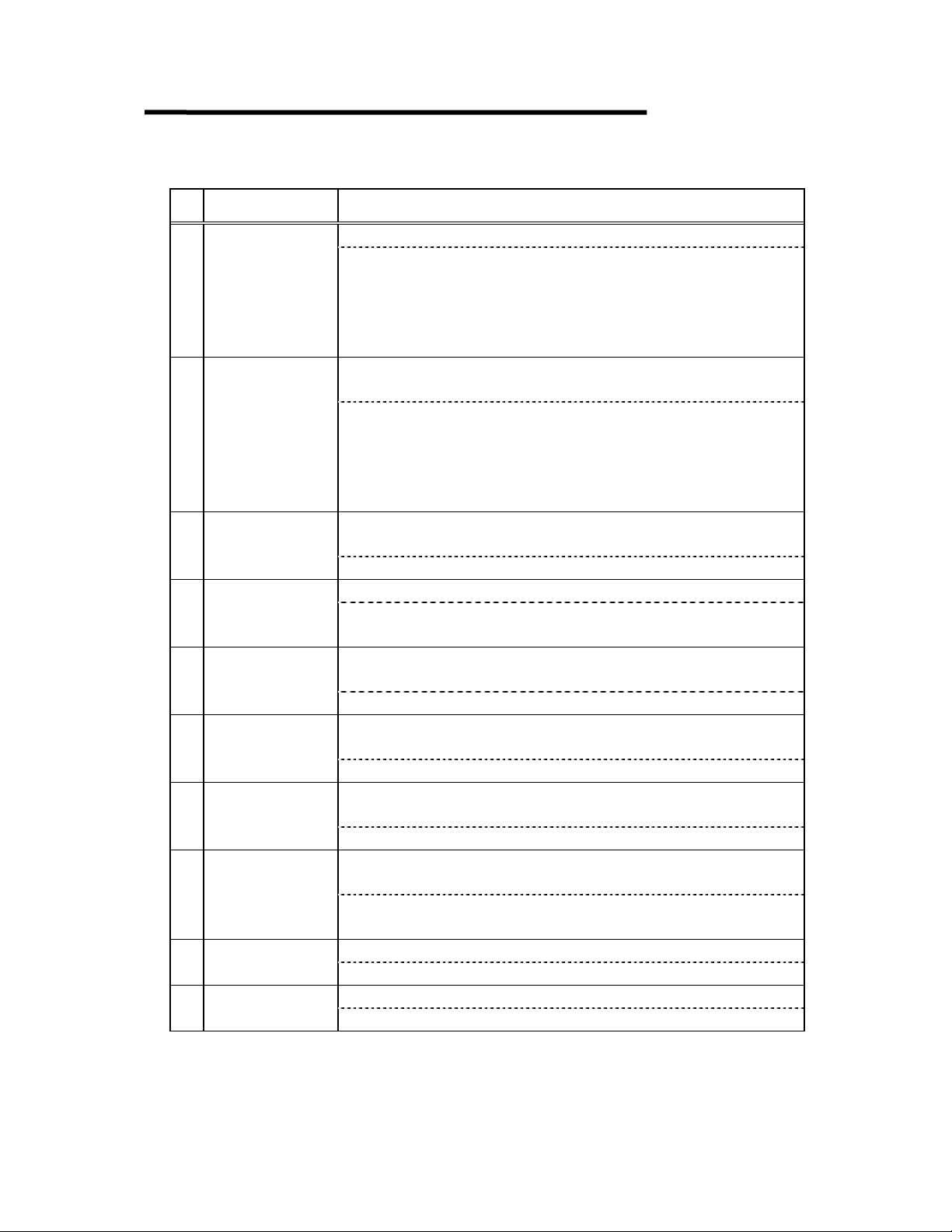
List of the contents of OP-SUPPORTER detection error
No. Message/rank Error content/detail (troubleshooting)
1 M-CODE ERROR
(3)
2 NO PALLET#
(2)
3 PALLET# ERR
(2)
(3)
Occurrence of M-CODE cycle time over and that M-CODE
is out of the fixed range.
Error occurrence with a M-CODE which is different from
the M-CODE registered.
In the case of the error occurrence despite of executing a
correct M-CODE, please contact us.
In the case of executing pallet change, "0" is indicated for
pallet No. informed for the ladder.
Please contact us.
In the case of executing pallet change, pallet No. indicated
by the ladder is out of range.
Please contact us.
Default rank of tool mass is not set or out of range.4 ZERO TL-MASS
In the case of no setting of tool mass in tool data, default
rank set with parameter is used, but this fault rank is not set
in the parameter. Please contact us.
- 1 -
Page 4
OP-SUPPORTER
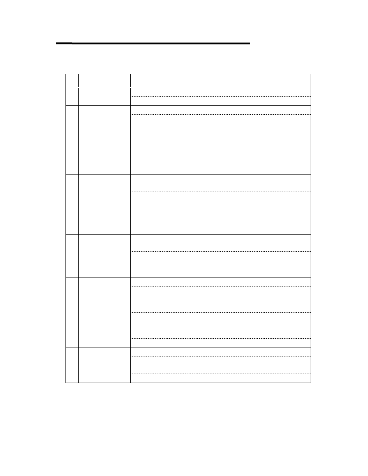
No. Message/rank Error content/detail (troubleshooting)
When to do teaching AC data, no tool is in the spindle.5 NO SP-TL(AC)
(3)
6 NO S DATA
(1)
7 NO F DATA
(1)
(3)
9 POT# ERROR
(3)
10 TL-OFS UP ER
(3)
11 NO MAG SEL1
(2)
12 REM-TL OVER
(3)
(3)
(3)
In the case of doing teaching of AC data, change the data of the
tool mounted in the spindle. However, tool pot No. mounted in the
spindle is unknown. In the case of manual mounting of the tool in
the spindle, set the spind le tool pot No. in the TOOL POSITION
screen.
In spite of assigning process condition, rota tion speed is not set in
the tool data.
Process condition is indicated with G205 A* (*:1-3) in NC
program but process condition (rotation speed) is not reg istered in
the tool data. Register process condition using TOOL DATA
DETAIL screen or select the mode without process condition
setting (G205 A*).
In spite of assigning process condition, feeding to tool data is not
set.
Same as the above. (However, feeding of process condition)
Offset of magazine change is not registered or out o f range.8 NO MAG OFFS
Mistake is in paramete r f ile.
Please contact us.
When converting pot No. to pot No. (POS) and magazine No.,
error occurred.
Please contact us.
Both tool length reading demand and tool radius reading demand
become ON at the same time.
Please contact us.
Manual set demand of tool data becomes ON but magazine No. is
not indicated.
Please contact us.
There is not room for the area keeping infor mation of the re moved
tool.
As the storage tool data is full, no more tool data can be stored.
Delete unnecessary too l data .
No optional para mete r f ile is in CNC memor y.13 NO OPT FILE
Please contact us.
No parameter file is in C N C memo r y.14 NO PAR FILE
Please contact us.
- 2 -
Page 5
OP-SUPPORTER
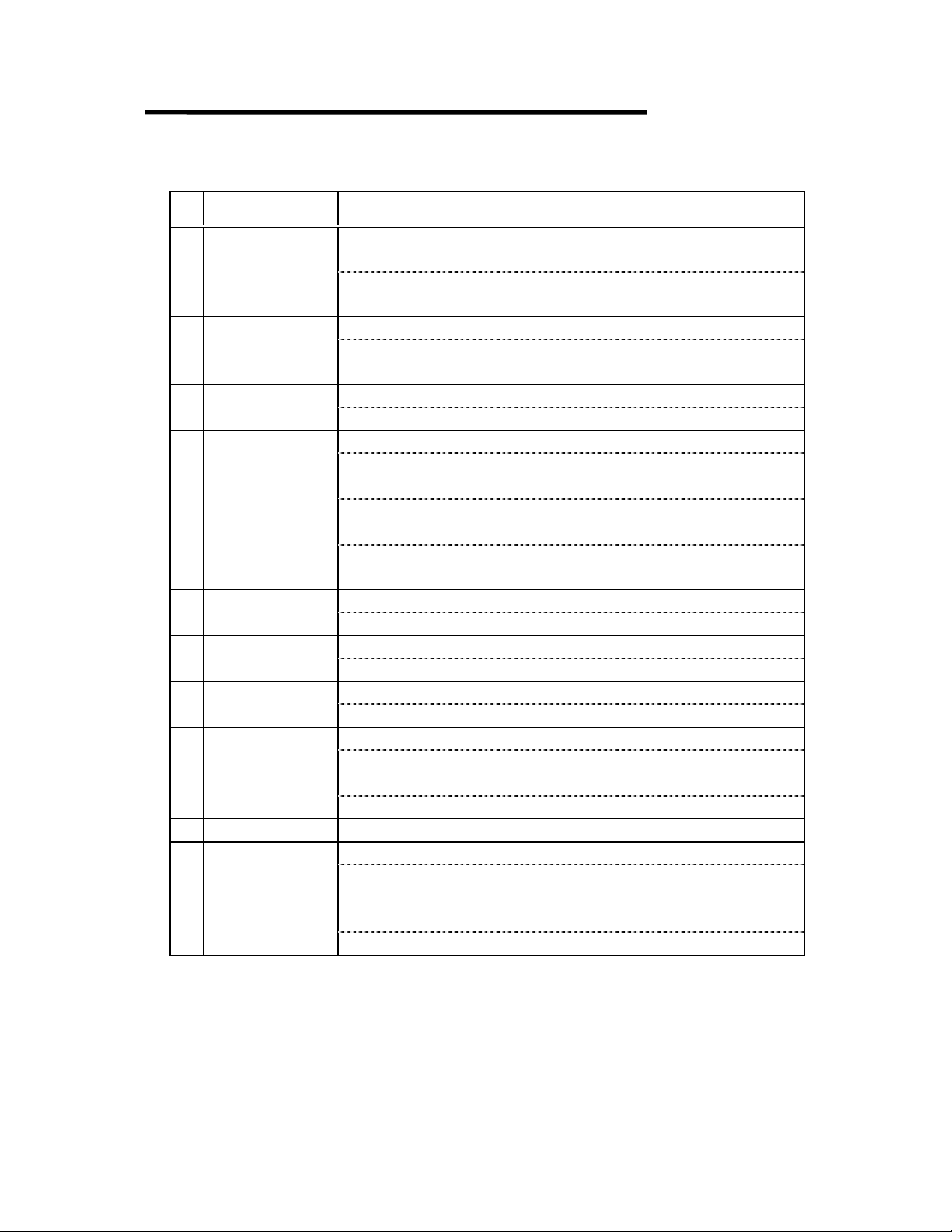
No. Message/rank Error content/detail (troubleshooting)
No tool information file is in CNC memory.15 NO TL FILE
(3)
(3)
(3)
18 NO SP-TL(TU)
(3)
19 NO SP-TL(BR)
(3)
(2)
21 NO SERIAL#
(3)
22 SERIAL# = 0
(3)
(3)
(3)
Please contact us.
Point indication of measured position is out of range.16 MES PT ERROR
In the case of having plural measuring positions for one work,
indication of the point is out of range.
Please contact us.
Checking code of optional parameter shows error.17 OPT-CHK ERR
Error is in the parameter to set optional function. Only ALARM
HISTORY screen can be executed under this condition.
Please contact us.
When to read tool compensation value in CNC memory, no tool is
in the spindle.
In the case of reading too l compensation value, renew the data for
the pot No. mounted in the spindle. However, pot No. mounted in
the spindle is unknown. In the case of mounting a tool in the
spindle manually, set the pot No. of spindle tool using TOOL
POSITION screen.
In the case of the occurrence of tool break or AC error, no tool is in
the spindle.
Tool pot No. mounted in the spindle is unknown. In the case of
mounting a tool in the spindle manually, set spindle tool using
TOOL POSITION screen.
Trigger signal comes ON without selecting magazine.20 NO MAG SEL2
Please contact us.
There is a tool installation instruction, but no tool data of instructed
SERIAL # is saved.
Register tool data using TOOL DATA DETAIL screen.
There is a tool installation instruction, but SERIAL# indicated is
"0".
Designate the serial #.
Open error of tool da ta f ile (w ri ting).23 TL-FILE SVER
Cancel the edit lock.
0-No. of optional parameter file is out of range.24 OPTF ONO ERR
Set 0-No. in N511 of parameter file.
- 3 -
Page 6
OP-SUPPORTER
No. Message/rank Error content/detail (troubleshooting)
25 OFS# RD ERR
(2)
(1)
(1)
(1)
(1)
(1)
(1)
(1)
(1)
(3)
(3)
36
(3)
(3)
At the time of turning power on, process of reading common offset
(H. D) from common variable cannot be done normally.
Cut the power of CNC unit off and restart it. In the case of
recurrence, contact us.
Reading error of tool length and tool geometry.26 LEN-G E RDERR
Tool compensation value from CNC cannot be read correctly.
Input compensation value using TOOL DATA DETAIL screen.
Reading error of tool length and tool wear.27 LEN- W E RD ERR
Same as the above.
Reading error of tool radius and geometry.28 RAD-GE RDERR
Same as the above.
Reading error of tool radius and wear.29 RAD-WE RDERR
Same as the above.
Writing error of tool length and geometry.30 LEN-GE WTERR
Compensation value cannot be written correctly in CNC.
Input compensation value correctl y in CNC side s creen.
Writing error of tool length and wear.31 LEN-WE WTERR
Same as the above.
Writing error of tool radius and geometr y.32 RAD-GE WTERR
Same as the above.
Writing error of tool radius and wear.33 RAD-WE WTERR
Same as the above.
Error of inverse change process of function ON /O FF code.34 F-SW CHG ERR
Please contact us.
Error of inverse change process of M-CODE.35 M-CD CHG ERR
Please contact us.
0-No. of parameter file is out of range.37 PARF ONO ERR
Register 0-No. of parameter file in data register (MELDAS:
R2700, FANUC: D600).
Spindle tool pot No. of tool position table (SFTTLPOS) is out of range.38 SP-TL POT#E1
- 4 -
Page 7

OP-SUPPORTER
No. Message/rank Error content/detail (troubleshooting)
Pot No. error at the time of reading tool compensation value.39 SP-TL POT#E2
(3)
40 SP-TL POT#E3
(3)
41 TL-MAX OVER
(3)
There was an indication of renewal of tool compensation value (CNC
DATA-OP-SUPPORTER data), but because of mismatching of spindle
pot No. between OP-SUPPORTER's memory and the ladder, renewal
cannot be done.
Input the compensation value using TOOL DATA DETAIL screen.
In the case of mounting tool in the spindle manually or if the reset
operation is incorrect after pushing emergency button during tool
change (T, M6), there is a case of this error occurrence. In those cases,
set the spindle tool using TOOL POSITION screen.
Mismatching of spindle pot No. between OP-SUPPORTER memory
and the ladder.
Same as the above.
Tool number set in the parameter is beyond the number of tool data
table.
42 FA COMMU ERR
(3)
(3)
44 NO TAKE OUT
(3)
45 NO NEXT TOOL
(3)
As the result of communication with the FA controller, a
communication alarm occurred.
Please contact us.
Year number o f NC unit 's clo c k is o ut o f ra nge.43 NC CLOCK WRN
Set NC unit's clock.
The TOOL SET buttons was pushed without pushing the TOOL TAKE
OUT buttons.
Please release the alarm by the magazine operation panel. Next, please
push the TOOL SET buttons again after pushing the TOOL TAKE
OUT buttons.
This alarm happens when the TOOL SET buttons is pushed twice.
Please do only the alarm reset in this case.
The mounting tool is not set on the FA controller (TOOL
MANAGEMENT SY STEM) side though the TOOL SET buttons was
pushed.
Please push the TOOL SET buttons again after registering the
mounting tool on FA controller (TOOL MANAGEMENT SYSTEM)
side.
- 5 -
Page 8

OP-SUPPORTER
No. Message/rank Error content/detail (troubleshooting)
The TOOL TAKE OUT buttons was pushed two times.46 DBL TAKE OUT
(3)
47 SERIAL# 0SET
(3)
50 T-ID OUT ERR
(3)
Please release the alarm by the magazine operation panel.
The pot number and the tool number were not able to be written in the
common variable at T execute.
There is a possibility that the sequence circuit monopolizes the PMC
window.
It is an alarm of the OP-SUPPORTER program.48 PROG ERROR
Please contact us.
Common offset No. is not correctly registered.49 OFS# ERROR
Please select the "TOOL PARAMETER" screen, and register correct
common offset No.. Zero (0) is not permitted.
You tried to detach the ID tool without pushing the ID CONTROL
TOOL button.
Please push the TOOL TAKE OUT button after pushing the ID
CONTROL TOOL buttons.
Or, please push the TOOL TAKE OUT button after turning off the ID
flag on a "TOOL DATA DETAIL" screen.
- 6 -
Page 9

OP-SUPPORTER
No. Message/rank Error content/detail (troubleshooting)
Parameter error.90 PARAM-ERR NO
Error is in parameter file. Record the No. part and contact us.
91 OFF-T-OVR:NO
(3)
Shakehand signal ON/OFF error.
As for shakehand signal with OP-SUPPORTER and the ladder, signal
becomes ON at OP-SUPPORTER side but the trigger signal
corresponding to it didn't become OFF at the ladder side. This occurs
during operation which is stopped by the emergency button. In the
case of occurrence in normal operation, record the No. part and contact
us.
No. Content
M6 process
0
T process
1
Tool break process
2
Pallet process
3
AC data reading process
4
Tool length rea d ing p roc e ss
5
Tool in need of change process
6
M-CODE process
7
Tool magazine manual operation process
8
Tool removing process
9
Tool mounting process
10
Work measuring process
11
Tool ID reading process
12
Tool ID writing process
13
(3)
(3)
This is an alarm of the matrix magazine.92 MMG-ERR:NO
It is processing of the matrix magazine and the alarm is found.
Please refer to "Matrix magazine alarm details" of the appendix
for details.
The alarm happened on the OP10i side.93 OP10i ALM
Please look at the "OPS(BG) ALARM" screen. The alarm code
is understood.
- 7 -
Page 10

OP-SUPPORTER
No. Message/rank Error content/detail (troubleshooting)
Command was transmitted to ID controller but failed .100 Send Err :ID
(3)
(3)
(3)
103 End Cd.Er:ID
(3)
Confirm if it is ID tool. Operate to mount or dismount the tool.
Tried to open the circuit to ID controller but fai led.101 O pen Err : ID
Confirm if it is ID tool.
Operate to mount or dismount the tool.
Tried to receive a command from ID control ler bu t f ai led.102 Recv Err :ID
Confirm if it is ID tool.
Operate to mount or dismount the tool.
A reply command against the command transmit ter to ID contro ller
is faulty.
Confirm if it is ID tool.
Operate to mount or dismount the tool.
Does ID controller's IN-ZONE lamp light when the ID antenna
approaches ID? If this lamp does not light, the ID data cannot be
read.
The following is a list of end command replied from the ID
controller.
(End code list)
Type
Normal
Host
communication
error
↔ID
NC
Controller
Satellite
communication
error
ID
↔ ID
Controller
End code
0
1 Framing error in 1 character.
2 Parity error in 1 character.
3 Communication format error
4 Sum check error.
5
6
7
8 Communication error
9 Write verify error
Normal end
Write instruction to write
protect area.
ID chip (Tool No.)
nonconformity error.
Hardwa r e e r r o r i n ID s e ns o r s
(ID controller, read/write head,
Data carrier)
Name
- 8 -
Page 11

OP-SUPPORTER
No. Message/rank Error content/detail (troubleshooting)
Receive command from ID controlle r caused Su m check e rro r.104 SumChk.Er:ID
(3)
(3)
106 STD TL Er:ID
(3)
107 T No Er:ID
(3)
108 FA COM Er:I D
(3)
(3)
(3)
(3)
(3)
(3)
(3)
Check whether it is ID tool or not. Mount or dismount the tool
accordingly.
Receive command from ID controlle r caused t imeout err or.105 TimeOutEr:ID
Check whether it is ID tool or not. Mount or dismount the tool
accordingly.
The ID CONTROL TOOL button is pressed despite removal of
the ordinary tool.
Check the tool, and remove the tool again.
Please turn on "ID EN T" fla g of TOOL DATA DETAIL screen for
the tool with ID.
The TOOL NO. in the ID is diffe rent from the TOOL NO. in the
OP-SUPPORTER.
The TOOL NO. stored in the ID is different f rom the TOOL NO.
memorized in the OP-SUPPORTER.
Check the TOOL NO., and execute it again.
An error occurred during communication with the FA control
system.
Print the communication log of the FA control system and contact
TOYODA MACHINE WORKS, LTD.
The service life of the ID chip has exp ired.109 Life Er :ID
Writing to the ID is i mposs ib le. Replace the ID chip.
Data (Area 02) in ID chip is beyond the specifica tion range.110 Area02Er :ID
Unit setting 1 (mm/ inch) is only availab le w ith
Data (Area 03) in ID chip is beyond the specifica tion range.111 Area03Er :ID
Unit setting 2 (t i me/c ycle) is only available with
Data (Area 05) in ID chip is beyond the specifica tion range.112 Area05Er :ID
Tool weight setting is available within "00.0-99.9".
Data (Area 06) in ID chip is beyond the specifica tion range.113 Area06Er1:ID
Tool control No. setting (T call code) in tool No. is available with in
"0-99999999".
“
0”. ( mm)
“
0 o r 1”.
Data (Area 06) in ID chip is beyond the specification range.114 Area06Er2:ID
Tool control No. setting (Serial No.) in tool No. is available
within
"0-99999999".
- 9 -
Page 12

OP-SUPPORTER
No. Message/rank Error content/detail (troubleshooting)
Data (Area 07) in ID chip is beyond the specification range.115 Area07Er : ID
(3)
(3)
(3)
(3)
(3)
(3)
(3)
(3)
(3)
(3)
(3)
Tool length compensation amount setting is available within
"-999999 to 999999".
Data (Area 08) in ID chip is beyond the specification range.116 Area08Er : ID
Tool dia. Offset amount setting is available within
"-999999 to 999999".
Data (Area 09) in ID chip is beyond the specification range.117 Area09Er : ID
Data (Area 10) in ID chip is beyond the specification range.118 Area10Er : ID
Tool dia. Wear amount setting is available within
"-999999 to 999999".
Data (Area 11) in ID chip is beyond the specification range.119 Area11Er : ID
Tool life setting (time/frequency) is available within
"0 to 4999".
Data (Area 12) in ID chip is beyond the specification range.120 Area12Er : ID
Tool usable time and frequency setting is available within
"0 to 9998".
Data (Area 15) in ID chip is beyond the specification range.121 Area15Er1:ID
User area 3 (initial tool flag) setting is available in
Data (Area 15) in ID chip is beyond the specification range.122 Area15Er2:ID
User area 3 (tool breakage flag) setting is available in
Data (Area 15) in ID chip is beyond the specification range.123 Area15Er3:ID
User area 3 (AC error flag) setting is available in
"0 or 1".
Data (Area 15) in ID chip is beyond the specification range.124 Area15Er4:ID
User area 3 (AC data reference value) setting is available within
"0 to 99".
Data (Area 16) in ID chip is beyond the specification range.125 Area16Er1:ID
Setting of user area 4: RPM (S) in machining condition 1 is
available within
").
65000
"0 to 6500" (actually 10 times, i.e., "0 to
"0 or 1".
"0 or 1".
- 10 -
Page 13

OP-SUPPORTER
No. Message/rank Error content/detail (troubleshooting)
Data (Area 16) in ID chip is beyond the specification range.126 Area16Er2:ID
(3)
(3)
(3)
(3)
(3)
(3)
(3)
(3)
(3)
(3)
136 TL-I/O-ER:ID
(3)
Setting of user area 4: Feed rate in machining condition 1 is
available within
When in mm : 1234 -> 12340 mm/min
When in inch : 1234 -> 123.4 inch/min
"0 to 6500"
Data (Area 17) in ID chip is beyond the specification range.127 Area17Er1:ID
Setting of user area 5: RPM in machining condition 2 is
available within
65000
").
"0 to 6500" (actually 10 times, i.e., "0 to
Data (Area 17) in ID chip is beyond the specification range.128 Area17Er2:ID
Setting of user area 4: Feed rate in machining condition 2 is
available within
When in mm : 1234 -> 12340 mm/min
When in inch : 1234 -> 123.4 inch/min
"0 to 6500".
Data (Area 18) in ID chip is beyond the specification range.129 Area18Er1:ID
Setting of user area 6: RPM (S) in machining condition 3 is
available within
65000
").
"0 to 6500" (actually 10 times, i.e., "0 to
Data (Area 18) in ID chip is beyond the specification range.130 Area18Er2:ID
Setting or user area 6: feed rate in machining condition 3 is
available within
When in mm : 1234 -> 12340 mm/min
When in inch : 1234 -> 123.4 inch/min
"0 to 6500".
Data (Area 19) in ID chip is beyond the specification range.131 Area19Er1:ID
Setting of AC data width in user area 7 is available within
".
to 99
Data (Area 19) in ID chip is beyond the specification range.132 Area19Er2:ID
Setting of AC data upper limit value in user area 7 is
available within
"0 to 150".
Data (Area 19) in ID chip is beyond the specification range.133 Area19Er3:ID
Setting of AC data lower limit value in user area 7 is
available within
"0 to 99".
Data (Area 14) in ID chip is beyond the specification range.134 Area14Er4:ID
User area 7 : Life limit rate "100~200" is available.
Specified pot No. is illegal.135 POT-NO.ER:ID
Please confirm pot No.
Mount or dismount the tool according l y.
The TOOL SET or TOOL TAKE OUT buttons was pushed
two times.
Please release the alarm by the magazine operation panel
"0
.
- 11 -
Page 14

OP-SUPPORTER
3. Saving of parame ter, etc
BE SURE TO DO SAVING
BE SURE TO DO SAVING
OP-SUPPORTER reads the parameter from the file of NC data format and keeps it in
the me mor y of s a vi n g t ype . Toyoda Machine Works implements this operation at the
time of shipping. After that, the contents of the saving type memory are referred to,
so that the file of NC data is not necessary. However, in the case of initialization or
change of CNC unit with some reason, be sure to save the bac k up of parameter file.
<
< NC data which is necessary to save the back up.
<<
Note 1) There are cases that O8152 and O8153 are not used.
Note 2) The caution at the expansion of part program storage (FANUC only)
O8150 O8151 O8152 O8153
In case of FANUC NC unit, if the part program storage is simply expanded
(example 160 -> 320m), the parameter for OP-SUPPORT ER and tool data
should be destroyed.
When it is need to expand the part program storage, contact to TOYODA.
- 12 -
Page 15

OP-SUPPORTER
4.Common varia ble to be use d
Following common variables are used for OP-SUPPORTER, so do not use them for
user program.
List of common variables to be used for OP-SUPPORTER
Address C e n t e n t s Used function
119 Measurement Macro type Measurement value X ï Measurement resu lt
120 data 1, 2 Measurement value Y ï display
121 Macro type Measurement value X ï
122 3, 4, 5 Measurement value Y ï
130 Pallet offset X ð APC management
131 Y ð
132 Z ð
133 Measurement data Base value X ï Measurement result
134 Base value Y ï display
135 Measurement macro typeï
136 Measurement value Y ï
137 Workpiece mounting Process data of face1 ð Multiple workpiece
138 Condition Process data of face2 ð mounting
139 Process data of face3 ð
140 Process data of face4 ð
531 Rotation limit value ð Tool control basic
532 Tool offset code (2) ð
533 Tool offset code (3) ð
534 Common offset Numbers (2) ð
535 Common offset Numbers (3) ð
550 Common offset D ð Tool control basic
551 Numbers (1) H ð
552 Tool offset Radius Geometry ð
553 (D) Wear ð
554 Length Geometry ð
555 (H) Wear ð
556 Machine condition Feed ð Machining condition
557 Selection Rotation ð setting function
558 Remember number
560
OP-SUPPORTER ↔ MACRO
No.2/3 Tool offset
function
- 13 -
Page 16

5. CNC parameter
The CNC parameters are set as shown below before shipment.
5.1 FANUC 16i(18 i) setting
• Setting
Data # Data
0000 ISO TV C
#7 #6 #5 #4 #3 #2 #1 #0 (Bit)
Setting input
Data type : Bit type
TVC : TV check
0:No 1:Yes
ISO : Punchin g code
0:EIA CODE
Data # Data
0100 NCR
#7 #6 #5 #4 #3 #2 #1 #0 (Bit)
1:ISO CODE
OP-SUPPORTER
Setting input
Data type : Bit type
NCR : EOB character in ISO code for punching
0:LF CR CR
Data # Data
3032 Allowable No. of T code characters
Parameter input Set "8" .
Data type : Byte type
Data unit : Integer
Data range : 1 - 8
1:LF
• Attention
6000 #3(V15) and 6004 #5(D15) are parameters of the tool offset. Please adjust
these two parameters to 0. When the parameter is changed to 1, the tool offset is
not correctly register ed.
- 14 -
Page 17

6. Tool ID data specification table
OP-SUPPORTER
Area Content Byte
00 Write protect 2 ✕✕Write "00".
01 ID chip life control 1 ✕✕
02 Setting unit 1 (mm/inch) 1 ¡ ✕ 0: mm 1: inch
03 Setting unit 2 (time/count) 1 ¡¡0: Time 1: Count
04 Tool large-bore mark 1 ✕✕Unused
05 Tool mass 4 ¡¡Kg (Exp 99.9)
06 Tool No.
07 Tool length compensation value 9 ¡¡
08 Tool diameter compensation value 9 ¡¡
09 Tool length wear 8 ¡¡
10 Tool diameter wear 8 ¡¡
11 Tool life set value (time/count) 4 ¡¡In minutes for time
12 Tool service time/count 4 ¡¡In minutes for time
13 User area 1 Control No.
(serial No.)
14 User area 2 Life limit ratio
15 User area 3 Tool flag + AC data
16 User area 4 Machining
condition 1
17 User area 5 Machining
condition 2
18 User area 6 Machining
condition 3
19 User area 7 AC data
20 User area 8 Spare 8 ✕✕
21 User area 9 Spare 8 ✕✕
M/C side
RW
12 ¡ ✕
8 ¡¡
8 ¡¡
8 ¡¡
8 ¡¡
8 ¡¡
8 ¡¡
8 ¡¡
Remarks
Lowermost 8 digits: Tool
No. (T call code)
00000999
Life limit ratio
11100099
AC alarm
Tool breakage
First tool
Uppermost 4 digits : S
Used by multiplying by 10.
Lowermost 4 digits : F
mm :1234->12340(mm/min)
inch :1234 ->123.4(inch/min)
99 999
99 0
Upper limit value
Width
AC data
reference
value
Lower limit
value
- 15 -
 Loading...