

Page 1
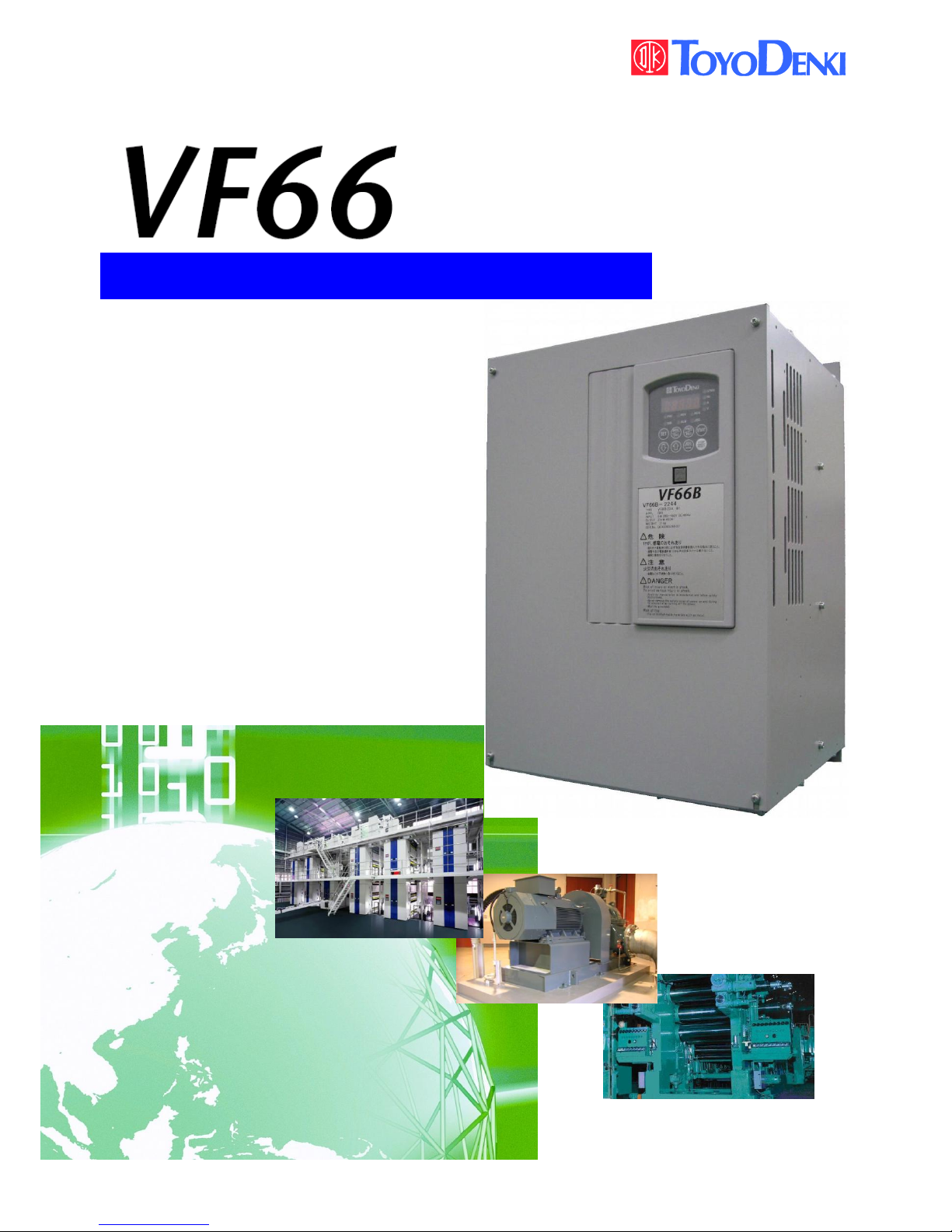
TOYO INTELLIGENT INVERTER
CC66-Z Operating Manual
Page 2

1
Foreword
Thank you for choosing optional circuit board for Toyo VF66B inverter.
This instruction manual contains information regarding the CC66-Z Optional Circuit Board for the
VF66B Inverter. For correct use, please carefully read this instruction manual prior to using the CC66-Z.
This instructions manual explains a setup of the function of CC66-Z, the wiring method, and a VF66B
inverter. Refer to a "CC66-Z communications protocol description" for CC-Link communication function.
In order to accommodate the many special functions to a wide variety of applications in addition to the
basic inverter functions, please thoroughly read the instruction manual of the inverter as well as any
other applicable specialized instruction manuals.
The communication specification of CC66-Z corresponds to CC-Link Ver1.1 and CC-Link Ver2.0.
Page 3
2
Please read before use
For safety
Before installing, operating, maintaining and inspecting CC66-Z option, please read this manual and all other
appendices thoroughly in order to get familiarize with the feature of this option, safety information and
correct handling. For safe operation, be sure to also thoroughly read the instruction manual of the inverter. In
this instruction manual, the safety instructions are classified in to two levels: DANGER and CAUTION.
DANGER
Indicates a hazardous situation which may result in death or serious injury if it
is handled improperly.
CAUTION
Indicates a hazardous situation which may result in moderate or minor injury
or only in property damage if it is handled improperly. However, such a
situation may lead to serious consequences depending on circumstances.
CAUTION [Installation]
Do not use optional circuit board if you discover damage or deformation during unpacking.
Doing so may cause optional circuit board failure or malfunction.
Do not place any flammable materials near the optional circuit board.
Doing so may cause a fire.
Do not allow the optional circuit board to drop, fall over or sustain severe impacts.
Doing so may cause optional circuit board failure or damage.
Do not install or operate the optional circuit board if it is damaged or has any of its parts missing.
Doing so may lead to personal injury.
DANGER [Wiring]
Before wiring, make sure the power is OFF.
Failure to do so may cause an electric shock or fire.
Wait more than 10 minutes after turning the power OFF before opening the unit case lid.
Failure to do so may cause an electric shock or fire.
Make sure that the unit is correctly earthed.
Failure to do so may cause an electric shock or fire.
Wiring must be done by skilled technicians.
Failure to do so may cause an electric shock or fire.
Wire the unit after it is installed.
Failure to do so may cause an electric shock or fire.
CAUTION [Wiring]
Make sure that communication cables and connectors are properly installed and locked in place.
Failure to do so may cause optional circuit board failure or malfunction.
Page 4
3
DANGER [Operation]
Turn the power ON after fitting the inverter front cover.
Do not remove the cover while the power is ON.
Failure to do so may cause an electric shock.
Do not operate any switch with wet hands.
Failure to do so may cause an electric shock.
Do not touch the inverter terminals while the power is ON, even if the inverter is in the idle state.
Failure to do so may cause an electric shock.
If the alarm is reset while the operation signal kept input, the inverter will suddenly restart. Reset the
alarm after making sure that the operation signal is OFF.
Failure to do so may lead to personal injury.
The inverter can be set to operate in a wide range of speed. Operate the inverter after sufficiently
checking the allowable range of the motor and equipment.
Failure to do so may cause personal injury, equipment failure or damage.
CAUTION [Operation]
The inverter radiating fin and the radiating resistance are hot. Do not touch them.
Failure to follow this warning may cause burns.
DANGER [Maintenance, inspection and parts replacement]
Always turn the power OFF before inspecting the inverter.
Failure to do so may cause an electric shock, personal injury or fire.
Unauthorized persons shall not perform maintenance, inspection or parts replacement.
Use insulated tools for maintenance and inspection.
Failure to do so may cause electric shock or personal injury.
DANGER [Other]
Never modify the unit.
Doing so may cause electric shock or personal injury.
CAUTION [General precautions]
Some illustrations given in this manual show the inverter from which the covers or safety shields have been
removed to illustrate the details. Before operating the inverter, reinstall the covers and shields to their
original positions and the inverter according to this manual.
These safety precautions and specifications stated in this manual are subject to change without notice.
Page 5

4
Table of contents
Please read before use ....................................................................................................................................................... 2
For safety ......................................................................................................................................................................... 2
Chapter 1 Functional outline ......................................................................................................................................... 5
Chapter 2 Basic specification ........................................................................................................................................ 6
2.1 Multifunctional input/output terminal specification .......................................................................... 6
2.2 Analog input/output terminal specification ........................................................................................... 7
2.3 PG input/output terminal specification .................................................................................................... 7
2.4 CC-Link communication terminal specifications .................................................................................. 7
2.5 CC-Link communication specification ....................................................................................................... 8
2.6 Other ....................................................................................................................................................................... 9
Chapter 3 Description of substrate ......................................................................................................................... 10
3.1 Name of each part .......................................................................................................................................... 10
3.2 CC66-Z switches .............................................................................................................................................. 11
3.3 Installation of CC66-Z .................................................................................................................................... 12
3.4 LED operation ................................................................................................................................................... 14
Chapter 4 Multifunction input/output specification ........................................................................................... 15
4.1 Multifunction input ........................................................................................................................................ 15
4.2 Multifunction output ..................................................................................................................................... 17
Chapter 5 Analog input/output function ................................................................................................................. 19
5.1 Analog input (2) ............................................................................................................................................... 19
5.2 Analog input (2) input gain and offset adjustment .......................................................................... 20
5.3 Analog input (2) usage instructions ........................................................................................................ 22
5.4 Analog output (2) ............................................................................................................................................ 25
5.5 Analog output (2) gain offset adjustment ............................................................................................ 26
Chapter 6 PG input/output function ....................................................................................................................... 28
6.1 PG input signal ................................................................................................................................................. 28
6.2 PG output signal .............................................................................................................................................. 30
Chapter 7 CC-Link communication function ........................................................................................................ 31
7.1 Connection method of a communication cable.................................................................................. 31
7.2 Setup of CC-Link communication function ........................................................................................... 31
Page 6
5
Chapter 1 Functional outline
CC66-Z is remote device station apparatus corresponding to CC-Link Ver.2.0. CC66-Z is used connecting
with the PC board (VFC66-Z) in a VF66B inverter. CC66-Z is equipped with an analog input/output function,
multifunctional input/output function, and PG input/output function other than extended cyclic
transmission and the cable length relief between stations as CC-LinkVer.2.0 function.
CC-Link is the communication specification of the high-speed FA network developed in Japan, and realizes
the data communication network corresponding to a multi vendor.
By CC-Link communication function of CC66-Z, operation instructions, speed instructions, torque
instructions, etc. are inputted into a VF66B inverter, or a monitor can do the operational status and the
protection state of an inverter, current, voltage, etc. Moreover, the setting data of an inverter read-out/rewrites
and read-out of trace back data, read-out of a protection history, and read-out of monitor data can be
performed. Refer to a "CC66-Z communications protocol description" for CC-Link communication function.
Moreover, it can be used as an input/output signal of the built-in PLC function of VF66B inverter. Refer to the
description of VF66 PCTool for a built-in PLC function.
CAUTION [Safety precautions]
Carefully read the instruction manual before use, and use the inverter correctly.
Our inverter and optional circuit board are not designed or manufactured for the purpose of use in
life-support machines or systems.
If you intend to use the product stated in this document for special purposes, such as passenger cars,
medical devices, aerospace devices, nuclear energy controls and submarine relaying machines or systems,
consult our sales department.
This product is manufactured under strict quality control. However, if it is used in critical equipment in
which inverter and optional circuit board failure may result in death or serious damage, provide safeguard to
avoid serious accidents.
If you wish to use this inverter with loads other than three-phase AC traction, please contact us.
To use this product, electrical work is necessary. The electrical work must be done by qualified expert.
Page 7
6
Chapter 2 Basic specification
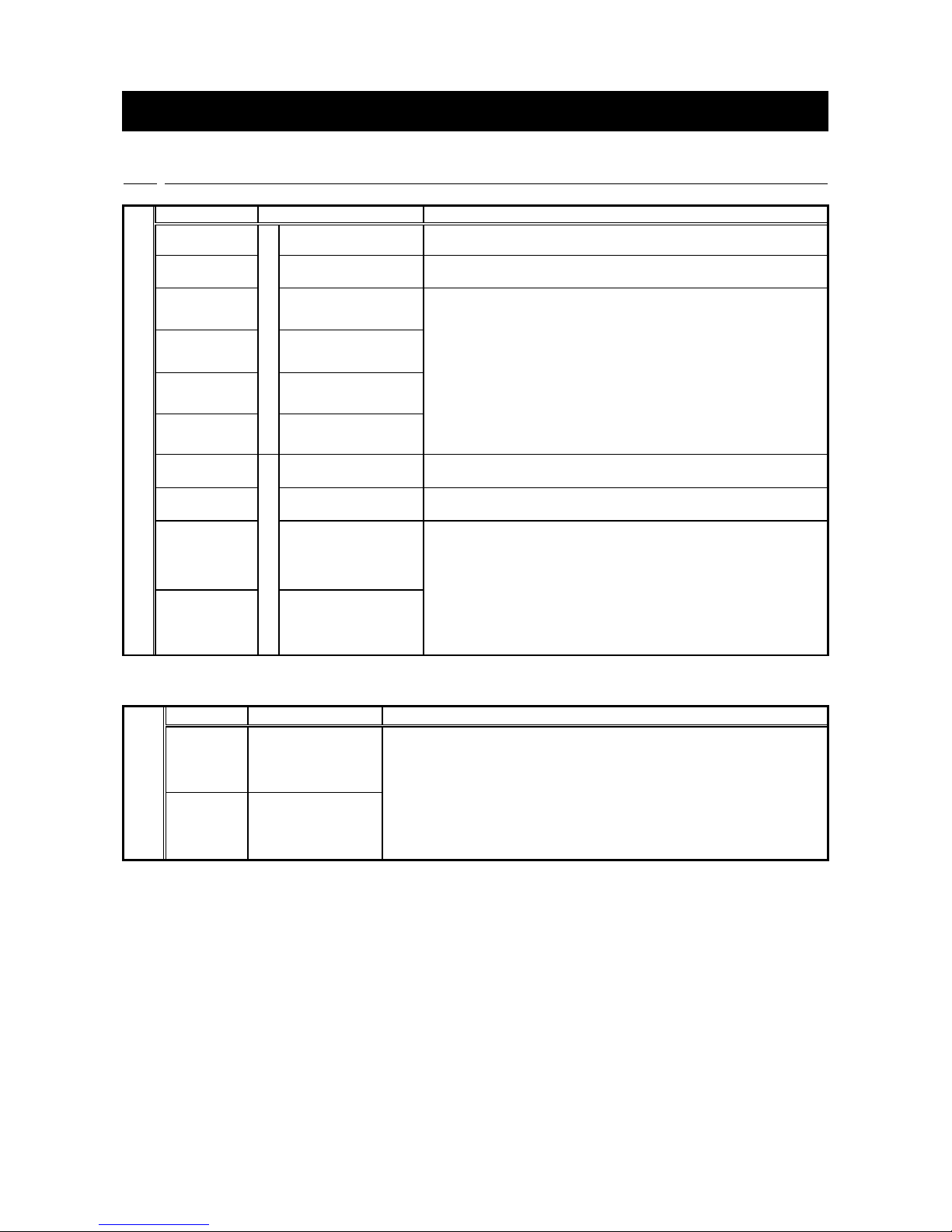
2.1 Multifunctional input/output terminal specification
Multifunction input/output terminal
CC66-Z Terminal TB1
Terminal No.
Use
Description
PS
(2 Terminal)
Multifunction input
+12V power terminal
Output +12V of DC voltage
G
(2 Terminal)
GND terminal
Never connect GND terminal to the earth.
Never touch nor connect PS terminal and G terminal.
MI6
Multifunction input
terminal (6)
(Maximum input voltage DC24V/Maximum input current 3mA)
By input the signal in multifunction input terminal, the same
operation can be done as that of VF66B inverter console.
[In the initial condition, the VF66B inverter setting parameter for
the C area are set to:
・For multifunction input terminal (6), Preset speed selection 1
・For multifunction input terminal (7), Preset speed selection 2
・For multifunction input terminal (8), Preset speed selection 3
・For multifunction input terminal (9), Accel./decel time selection 1]
※See the instruction manual of the inverter for details of
multifunction input terminals.
MI7
Multifunction input
terminal (7)
MI8
Multifunction input
terminal (8)
MI9
Multifunction input
terminal (9)
P
Multifunction output
External power supply
connecting terminal
P terminal is connected to the external power supply(DC).
COM
Common potential
connection terminal
Never connect COM terminal to the earth.
MO3
Multifunction output
terminal (3)
(Max. voltage DC24V/Max. Output current 20mA)
Multifunction output terminal outputs the signal depends on the
situation of performance.
[In the initial condition, the followings are set by VF66 inverter
setting parameter:H area.
・For multifunction output terminal (3), not used.
・Multifunction output terminal (4), torque detected.]
※Refer to the instruction manual of the inverter for the details of a
multifunctional input terminal.
MO4
Multifunction output
terminal (4)
Multifunction input source mode/sink mode configuration jumper connector
CC66-Z Jumper
Connector
Connector
Use
Description
CN-SO
Source mode
・Setting source mode/sink mode is conducted by replacement of
jumper socket CN-SI, CN-SO.
・In replacement of jumper socket, please cut off the power supply.
[In the initial condition, the source mode is set.]
・ In case of source mode, the switch etc. is connected between
multifunction input terminal (6) to (9) and PS terminal, and turn on/ off.
・In case of sink mode, the switch etc. is connected between multifunction
input terminal (6) to (9) and G terminal, and turn on / off.
For the detail information, please see the Chapter 4.
CN-SI
Sink mode
Page 8
7
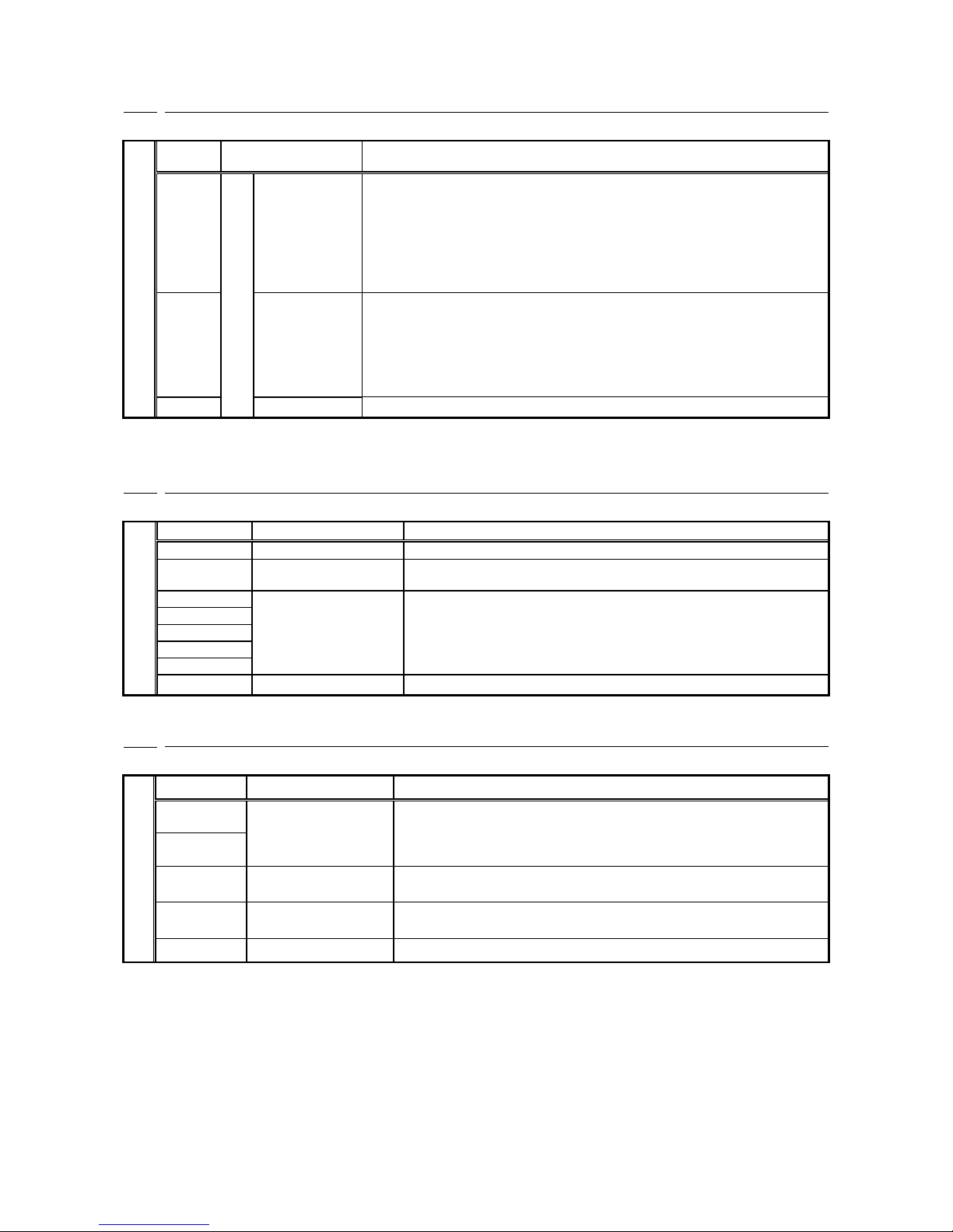
2.2 Analog input/output terminal specification
Analog input/output function
CC66-Z Terminal TB1
Terminal
No.
Use
Description
AIN2
Analog input/output
Analog input (2)
terminal
・Type of input can be selected from 0 to ±10V, 0 to 10V, 4 to 20mA by the
swift of SW1 and alternation of inverter setting parameter.
(Please refer to Chapter 5 for the change of the input range.)
・Input resistance is 150kΩ in input analog voltage.
・Input resistance is 250Ω in input analog current.
[0 to 10V is set in the initial condition. ]
※See the instruction manual of the inverter for details of analog input
terminal(2).
AOT2
Analog output
(2) terminal
・By changing the VF66B inverter configuration parameters, the output range
of the analog output (2) terminal can be set to either 0 to 10V or 0 to ±10V
(max current 1mA).
[In the initial configuration, the inverter output current is set at “5V/inverter
rated current”.]
※See the instruction manual of the inverter for details of analog output
terminal (2).
G2
GND terminal
Never connect G2 terminal to the earth.
2.3 PG input/output terminal specification
PG input/output function
CC66-Z Terminal TB2
Terminal No.
Use
Description
+12
+12V power terminal
Output +12V of DC voltage
G
(3 terminals)
GND terminal
Never connect GND terminal to the earth.
A
PG input terminal
Input A, B, U/Z, V, and W signal (complementary output) of 12 V power
PG respectively.
B
U/Z
V
W
PG-OUT
PG output terminal
Outputs a divided waveform of the PG A-signal.
2.4 CC-Link communication terminal specifications
CC-Link communication function
CC66-Z Terminal TB1
Terminal No.
Use
Description
DA
(2 terminals)
Communication signal
terminal
CC-Link communication terminal
Signal polarity of RS-485 (ISO/IEC8482)
DB
(2 terminals)
DG
Communication earth
terminal
RS-485(ISO/IEC8482)Signal line data earth terminal
SLD
Shield terminal of
communication cable
Connect the shield cable of a CC-Link communication cable
FG
Protective earth terminal
FG terminal is used when grounding all the station
Page 9
8
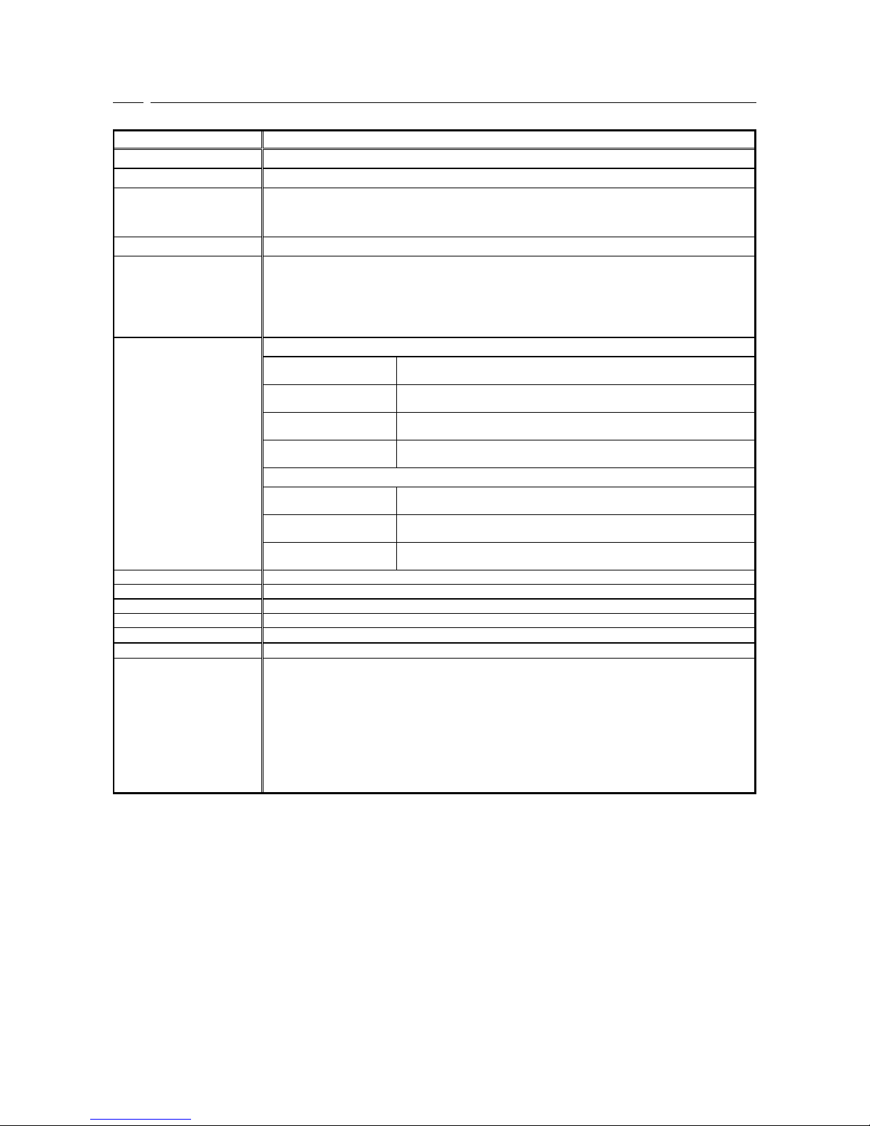
2.5 CC-Link communication specification
CC-Link communication specification of CC66-Z
Item
Specification
Communication protocol
CC-Link Ver1.1 CC-Link Ver2.0 Conformity
Station classification
Remote device station
Electrical charac-teristics of
physical layer
In conformity to RS-485(ISO/IEC8482)
+5V which insulated the power supply from the printed circuit board for inverter control
through the built-in DC/DC converter is supplied.
Maker code
0993H
The number of occupancy
sations, and a multiple
setup
Sets up by the console of the main part of a VF66B inverter.
(CC-Link Ver1.1 and CC-Link Ver2.0 change is possible)
At the time of CC-Link Ver1.1 selection Number of occupancy stations 1-4 station.
Multiple setup is twice, 4 times, and 8 times by the number one station fixation of occupancy
stations at the time of CC-LinkVer2.0 selection.
The number of statons of
a link
Ver1.1
One station occupancy
Remote input and output RX, RY: 32 points (fixation)
Remote register RWr, RWw:4 word
Two station occupancy
Remote input and output RX, RY: 32 points (fixation)
Remote register RWr, RWw:8 word
Three staion occupancy
Remote input and output RX, RY: 32 points (fixation)
Remote register RWr, RWw:12 word
Four station occupancy
Remote input and output RX, RY: 32 points (fixation)
Remote register RWr, RWw:16 word
Ver2.0
One-station occupancy
Twice
Remote input and output RX, RY: 32 points (fixation)
Remote register RWr, RWw:8 word
One-station occupancy
4 times
Remote input and output RX, RY: 32 points (fixation)
Remote register RWr, RWw:16 word
One-station occupancy
8 times
Remote input and output RX, RY: 32 points (fixation)
Remote register RWr, RWw:32 word
Transmission procedure
Half duplex transmission
Synchronization system
Frame synchronization
Modulation system
Base band system
Encoding system
NRZI (Non Return to Zero Inverted) method
Connection, wiring system
Terminal block 3 wires type
Connection cable
3 core twisted-pair cable with a shield with the cable only for CC-Link
Transmission speed and
transmission distance
To be set by built-in console of VF66B Inverter unit
156kpbs - A maximum of less than 1200m of the total extension of a cable
625kpbs - A maximum of less than 900m of the total extension of a cable
2.5Mpbs - A maximum of less than 400m of the total extension of a cable
5Mpbs - A maximum of less than 160m of the total extension of a cable
10Mbps - A maximum of less than 100m of the total extension of a cable
Cable length between stations of 20 cm or more
* The cable corresponding to CC-LinkVer1.1, 110ohms of terminator use
* Cable length between stations : Connection communication cable length between a master
station and a slave station or between slave stations
Page 10
9
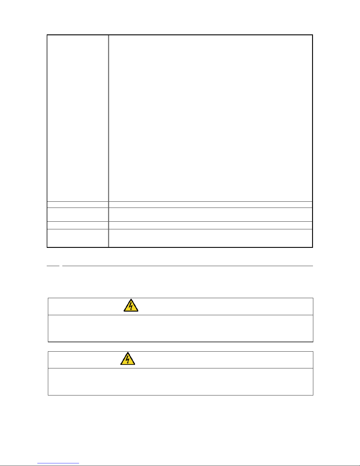
Number of connection
station
Number of connection is forming the following formula.
・(a+a2+a4+a8)+(b+b2+b4+b8)*2+(c+c2+c4+c8)*3+(d+d2+d4+d8)*4 ≦ 64
・(a*32+a2*32+a4*64+a8*128)+(b* 64+b2* 96+b4*192+b8*384)+
(c*96+c2*160+c4*320+c8*640)+(d*128+d2*224+d4*448+d8*896)≦8192
・(a* 4+a2* 8+a4* 16+ a8* 32)+(b* 8+b2* 16+b4* 32+b8* 64)+
(c*12+c2* 24+c4* 48+c8* 96)+(d*16+d2* 32+d4* 64+d8*128)≦2048
a : Number of a 1 time setup by one-station occupancy
b : Number of a 1 time setup by two-station occupancy
c : Number of a 1 time setup by three-station occupancy
d : Number of a 1 time setup by four-station occupancy
a2: Number of a 2 time setup by one-station occupancy
b2: Number of a 2 time setup by two-station occupancy
c2: Number of a 2 time setup by three-station occupancy
d2: Number of a 2 time setup by four-station occupancy
a4: Number of a 4 time setup by one-station occupancy
b4: Number of a 4 time setup by two-station occupancy
c4: Number of a 4 time setup by three-station occupancy
d4: Number of a 4 time setup by four-station occupancy
a8: Number of a 8 time setup by one-station occupancy
b8: Number of a 8 time setup by two-station occupancy
c8: Number of a 8 time setup by three-station occupancy
d8: Number of a 8 time setup by four-station occupancy
・16×A+54×B+88×C ≦ 2304
a:Number of offices of one-station occupancy
b:Number of offices of two-station occupancy
c: Number of offices of three-station occupancy
d: Number of offices of four-station occupancy
A: Number of a remote I/O station………………………………… Maximum of 64 sets
B: Number of a remote device station ……………………………… Maximum of 42 sets
C: Local station and the number of an intelligent device station…… Maximum of 26 sets
Setting of station number
1 to 64 : The number of offices is set up with the rotary switch on CC66-Z.
Communication control
system
Broadcasting polling
Error check system
CRC(X16+X12+X5+1)
Correspondence service
Cyclic transmission
Extended cyclic transmission
Cable length relief between stations
2.6 Other
Other standard specifications apply to VF66B inverter correspondingly. For more details, please refer to the
instruction manual of the inverter.
DANGER [Wiring]
Before wiring, make sure the power is OFF.
Failure to do so may cause an electric shock or a fire.
Substitution of Jumper socket is performed after certainly turning off an inverter.
Failure to do so may cause an electric shock, personal injury, equipment failure or malfunction.
CAUTION [Wiring]
G terminal, G terminal, and G2 terminal are not connected to a grounding by any means.
Doing so may cause equipment failure or damage.
Never connect or allow contact between the PS and G terminals.
Doing so may cause equipment failure or damage.
Page 11
10
Chapter 3 Description of substrate
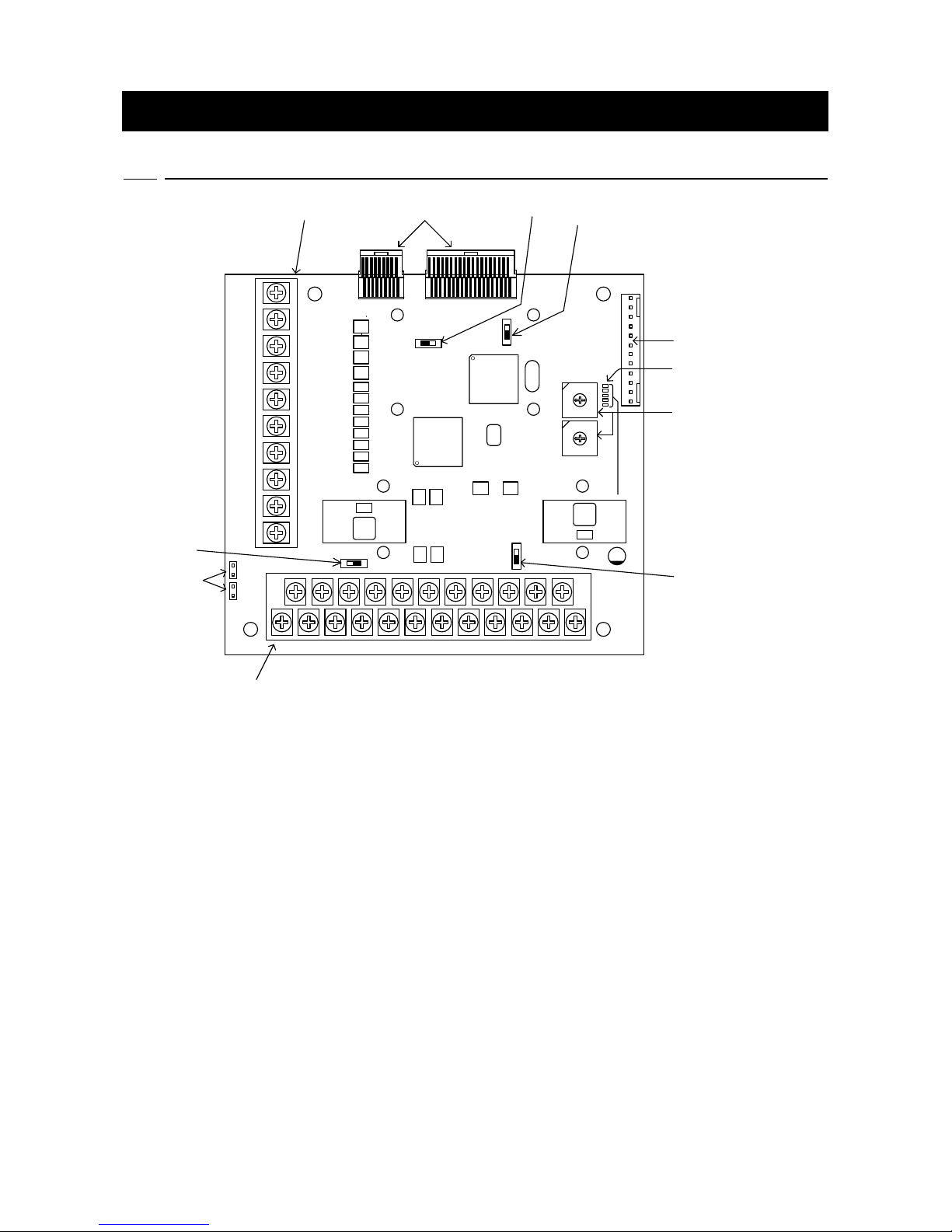
3.1 Name of each part
PS PS MI8 G G2 P COM DA DG SLD FG
MI6 MI7 MI9 G AIN2 AOT2 MO3 MO4 DA DB DB
CN-SI
CN-SO
PGOUT G W V U/Z G G B A +12
CC66-Z
TB1
TB2
SW1
SW3
SW2
SW4
LED1
LED3
LED5
LED6
LED4
CN3
CN1CN2
①
②
③
④
⑤
⑦
⑥
⑪,⑫,⑬,⑭,⑮
⑩
⑧
⑨
SW5
SW6
Figure3.1 CC66-Z substrate
① Connector to VFC66-Z (CN1,2)
② PG frequency dividing output switch (SW4)
③ PG signal ON/OFF switch (SW2)
④ Connector to external extension option“IOEXT66” (CN3)
⑤ Multi function input/output, Analog input/output terminal block (TB1)
⑥ Analog input(2) signal characteristic switching switch (SW1)
⑦ Multi functional input signal characteristic switching jumper connector (CN-SI, CN-SO)
⑧ PG input/output terminal block (TB2)
⑨ Terminator (110ohms) changeover switch (SW3)
⑩ CC-Link station number setting switch (SW5, SW6)
⑪ Power supply LED for CC-Link commnucation (LED1, PWR, green)
⑫ CC-Link communication operation LED (LED3, RUN, green)
⑬ CC-Link communication transmitting LED (LED5, SD, green)
⑭ CC-Link communication receiving LED (LED6, RD, green)
⑮ CC-Link communication unusual LED (LED4, ERR, red)
As connector connecting to ④, please use housing :5051-12, terminal coated gold :2759G or 2759PBG
producted by Molex. For connection to CN3 and usage of CN3 and so on, refer to the instruction manual
about IOEXT66.
Page 12
11
3.2 CC66-Z switches
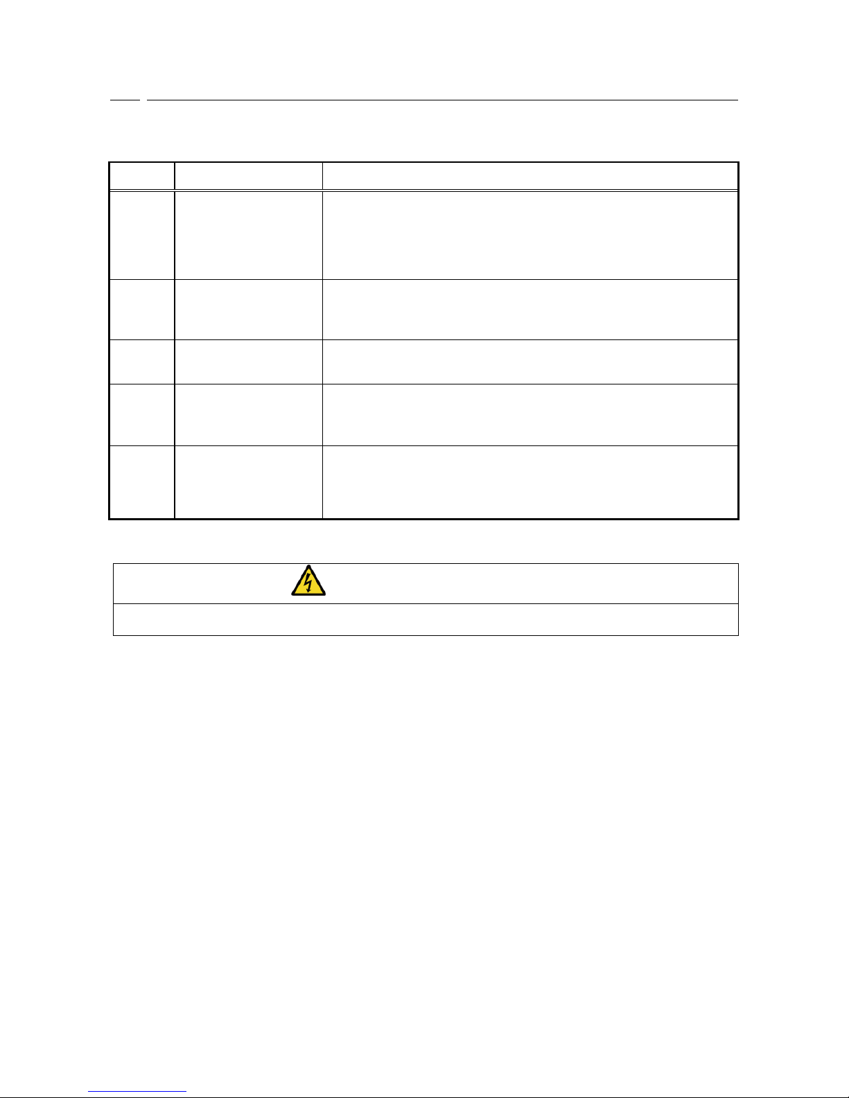
The switch on CC66-Z can be switched and various functions can be changed.
Each kind of function of switch on CC66-Z
Name of
switch
Use
Description
SW1
Analog input(2) signal
characteristic switching
switch
Switch input signal characteristic of analog input (2) terminal.
・0 to 10V, 0 to ±10V input when the switch is OFF.
・4 to 20mA input when the switch is ON.
[In the initial condition, the switch is set to OFF.]
※When you switch input range, please change the parameter of VF66B inverter.
For more detail, please refer to chapter 5.
SW2
PG signal ON/OFF
switch
Switch ON/OFF PG signal.
・PG signal is no effect when the switch is OFF.
・PG signal is available when the switch is ON.
[In the initial condition, the switch is ON.]
SW3
Terminator changeover
switch
ON/OFF of a terminator can be switched.
・A terminator is separated for a switch in OFF.
・A terminator is connected for a switch by ON.
SW4
PG frequency dividing
output switch
Switch output of PG frequency dividing signal.
・1/4 frequency dividing signal is output when the switch is side of 3.
・1/2 frequency dividing signal is output when the switch is side of 1.
[In the initial condition, the switch is set to position “3”.]
SW5,SW6
CC-Link station number
setting switch
Station number of CC-Link is set up.
・Please set up a station number by the decimal number of double figures, and it
is SW5 about a low ranking beam, and set up the beam of a higher rank in
SW6.
・A station number should set up 01-64.
DANGER [Switch]
Change of a switch is performed by certainly turning off the inverter.
Failure to do so may cause an electric shock, personal injury, equipment failure or malfunction.
Page 13
12
3.3 Installation of CC66-Z
サポート
オプション基板
コネクタ
SET66-Z基板
VFC66-Z基板
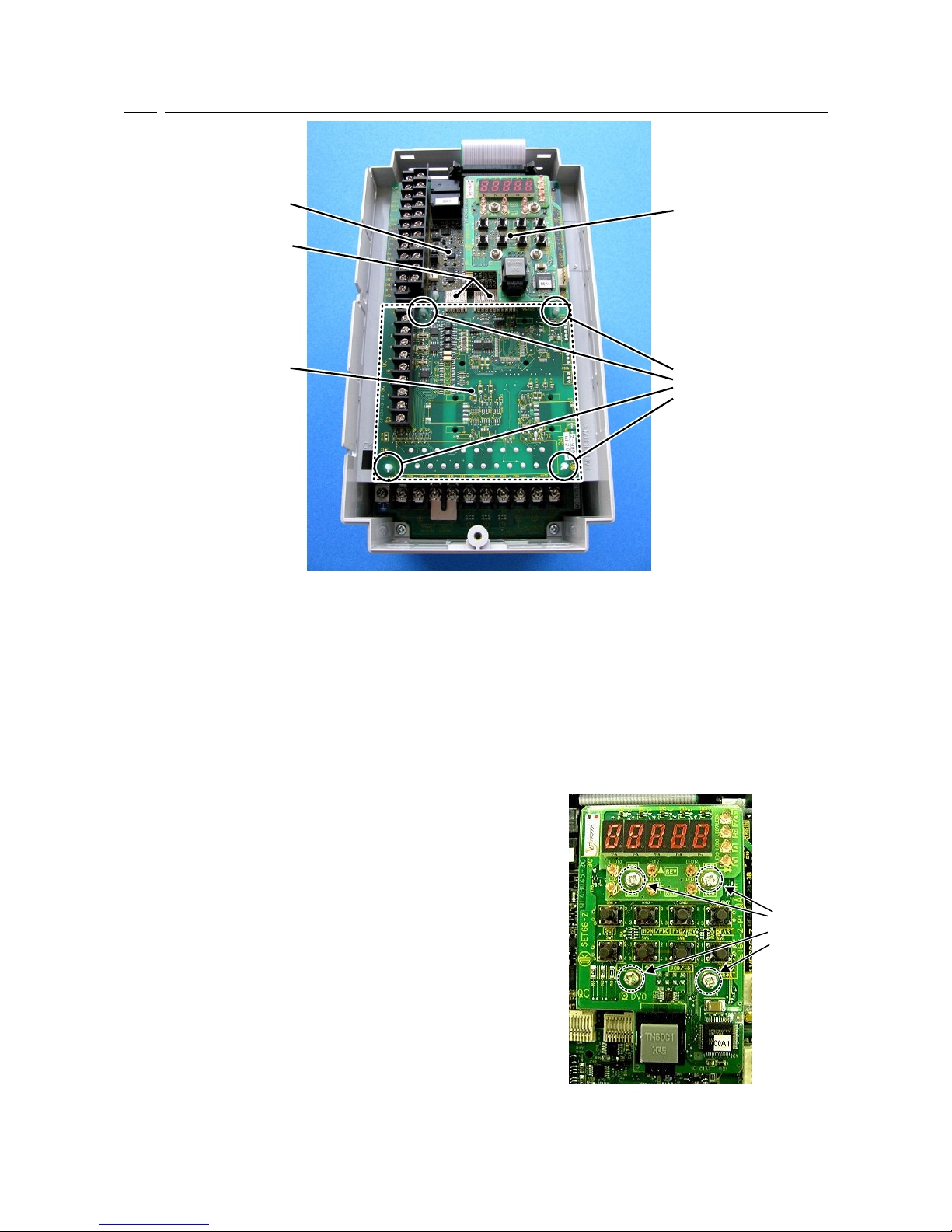
Figure 3.2 CC66-Z installation position (VF66B-2R222)
*For information about opening and closing the front cover, please refer to the instruction manual of the
inverter.
(1) Confirm that the power is off before performing any work.
(2) Install the CC66-Z board in the location designated by the dotted lines shown in Figure 3.2. (The figure
shows the VF66B-2R222 model, however, the installation location is the same for other models.) If another
optional circuit board is already installed, remove it by following the procedure described below. If another
optional circuit board is not already installed, skip to (6).
(3) In order to safely remove the optional circuit board, first
remove the SET66-Z board. Remove the 4 screws
indicated by the circles in the figure on the right. Pull the
SET66-Z board away from the VFC66-Z board in order to
detach it.
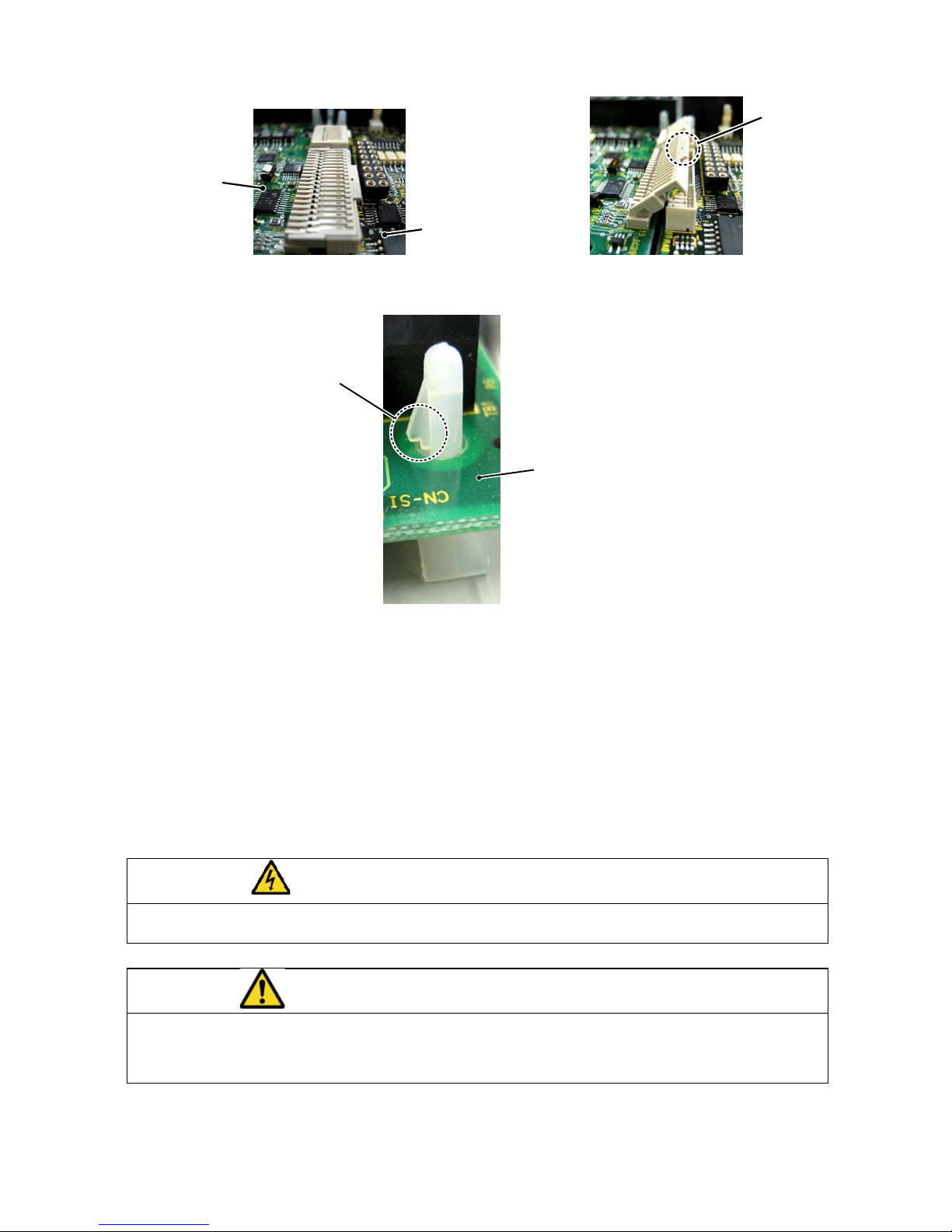
(4) Next, release the two connectors between the VFC66-Z
board and the optional circuit board. Figure 3.4 (a) shows
the connector in its engaged position. Pull up the tab to
release the connector as shown in Figure 3.4 (b).
(5) 4 board supports are included to mount the optional
circuit board to the inverter housing, as indicated by the
circles in Figure 3.2. Press down on the board support
locking hooks as shown in Figure 3.5 to remove the
optional circuit board.
ねじ
Figure 3.3 SET66-Z circuit board
Screws
VFC66-Z circuit board
Connectors
Optional circuit board
SET66-Z circuit board
Supports
Page 14
13
つまみ
オプション基板
VFC66基板
(a) Locked connector (b) Connector tab
Figure 3.4 Connector
爪
オプション基板
Figure 3.5 Support locking hook
(6) Align the four holes of the CC66-Z board with the 4 board supports indicated by the circles in Figure 3.2.
Push down on the board until the support locking hooks snap into place as shown in Figure 3.5.
(7) Align the tabs (shown in Figure 3.4 (b)) of the CC66-Z board connectors CN1 and CN2 with the VFC66-Z
board connectors CN7 and CN4. Press down on the tabs to engage with the connectors. Once the
connectors are correctly joined, it will look like Figure 3.4 (a). The movable part of the connector has some
elasticity and if the joint is weak, it may become disconnected. Ensure that is it properly locked in place.
(8) Install the SET66-Z board to its original position.
(9) Return the front cover to its original position.
DANGER [Installation/Removal]
Always confirm that the power is off before installing/removing any circuit boards.
Failure to do so may cause an electric shock, personal injury, equipment failure or malfunction.
CAUTION [Installation/Removal]
Avoid excess connection and disconnection of the connectors.
The connector mounting area may become loose, leading to problems such as poor connections.
Do not attempt to insert any object other than a compatible connector.
The connector mounting area may deform, leading to problems such as poor connections.
Optional circuit board
VFC66-Z circuit board
Optional circuit board
Locking hook
Tab
Page 15
14
3.4 LED operation
・LED1 operation
When operation of CC66-Z of an inverter during a stop or operation is normal, LED1 blinks at intervals of
about 1 second. Even if it switches on a power supply, when LED1 does not blink normally, failure of CC66-Z
can be considered.
・LED3 operation
When normal reception of the refreshment & polling from a master station is carried out normally, LED3
turns on CC66-Z. Refreshment & polling is data periodically transmitted to a slave station from a master
station, and if this communication breaks off fixed time, LED3 will go out.
・LED4 operation
The light is put out when LED4 has normal CC-Link communication. The light is switched on at the case
where CC-Link communication has abnormalities, and the time of a setup of the inaccurate station by SW5
and SW6 (a station number 0 and the station number containing the number of occupancy stations are 65 or
more).
・LED5 operation
LED5 is turned on when CC66-Z has taken out CC-Link communication transmitting data.
・LED6 operation
LED6 is turned on when CC66-Z has detected CC-Link communication receiving data.
CAUTION [Safety Precautions]
If LED1 is not operating normally, the CC66-Z or VFC66-Z board may be malfunctioning.
If this is the case, please contact us immediately.
Page 16
15
Chapter 4 Multifunction input/output specification
4.1 Multifunction input
CC66-Z
TB1
PS
4.7kΩ
MI7
MI6
4.7kΩ
MI8
4.7kΩ
MI9
4.7kΩ
G
CN-SO
CN-SI
Multifunction
input 6
Multifunction
input 7
Multifunction
input 8
Multifunction
input 9
External power source
(+12~+24V)
1. Source mode (with internal power source) 2. Source mode (with external power source)
TB1
PS
4.7kΩ
MI7
MI6
4.7kΩ
MI8
4.7kΩ
MI9
4.7kΩ
G
CN-SO
CN-SI
Multifunction
input 6
Multifunction
input 7
Multifunction
input 8
Multifunction
input 9
External power source
(+12~+24V)
CC66-Z
3. Sink mode (with internal power source) 4. Sink mode (with external power source)
Figure 4.1 Multifunction input connections
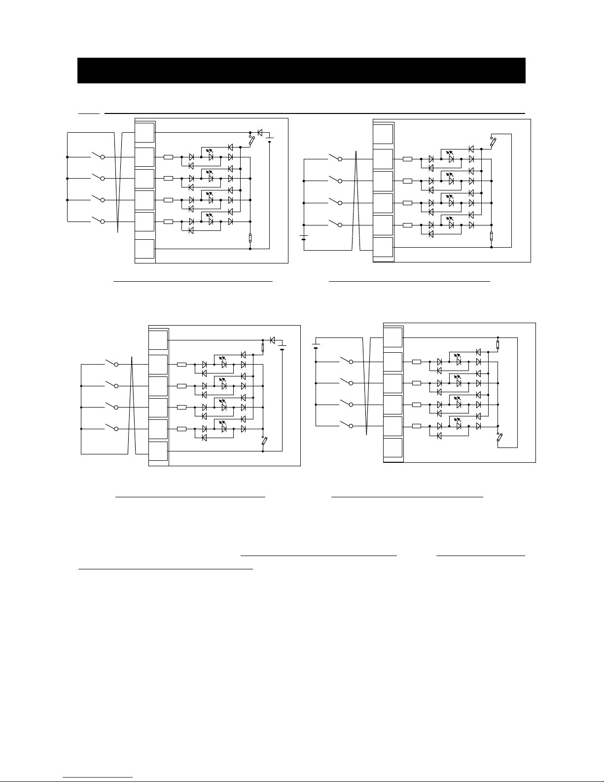
The CC66-Z can use the VF66B inverter multifunction input. The above figures show typical multifunction
input signal connection methods. The maximum allowable voltage is 24V and the maximum allowable
current for any one terminal is 3mA. For more information about the functions of the individual
multifunction input terminals, please refer to the instruction manual of the inverter.
The multifunction input signal can be set to either source mode or sink mode and an internal power source
or external power source can be chosen for the inverter. In the initial configuration, it is set to source mode.
To switch between source mode and sink mode, place a jumper shunt on either the CC66-Z jumper connector
CN-SO (source mode) or CN-SI (sink mode).
CC66-Z
TB1
PS
4.7kΩ
MI7
MI6
4.7kΩ
MI8
4.7kΩ
MI9
4.7kΩ
G
Internal power source
(12V)
CN-SO
CN-SI
Multifunction
input 6
Multifunction
input 7
Multifunction
input 8
Multifunction
input 9
TB1
PS
4.7kΩ
MI7
MI6
4.7kΩ
MI8
4.7kΩ
MI9
4.7kΩ
G
Internal power source
(12V)
CN-SO
CN-SI
Multifunction
input 6
Multifunction
input 7
Multifunction
input 8
Multifunction
input 9
CC66-Z
Page 17
16
Multifunction input related inverter parameters
Display
Items
Item Selection
Default Data
Unit
c-00
Multifunction input
place selection
0: Terminal block
1: Digital communication option
0: Terminal block
-
c-06
Multifunction input
terminal (6)
function selection
0: Preset frequency selection 1 (V/f mode)
Preset rotation speed selection 1 (vector mode)
1: Preset frequency selection 2 (V/f mode)
Preset rotation speed selection 2 (vector mode)
2: Preset frequency selection 3 (V/f mode)
Preset rotation speed selection 3 (vector mode)
3: Acceleration/deceleration time selection 1
4: Acceleration/deceleration time selection 2
5: Frequency UP command (MRH mode) (V/f mode)
Rotation speed UP command (MRH mode) (vector
mode)
6: Frequency DOWN command (MRH mode) (V/f mode)
Rotation speed DOWN command (MRH mode) (vector
mode)
7: Frequency hold (V/f mode)
Rotation speed hold (vector mode)
8: S-pattern acceleration/deceleration prohibition
9: Max. frequency reduction (V/f mode)
Max. rotation speed reduction (vector mode)
10: Droop control disabled
11: No function (V/f mode)
Speed/torque control selection (vector mode)
12: Forward/reverse operation command selection
13: DC brake command
14: No function (V/f mode)
Initial excitation command (vector mode)
15: External failure signal 1 (protection relay 86A enable)
16: External failure signal 2 (protection relay 86A enable)
17: External failure signal 3 (protection relay 86A enable)
18: External failure signal 4 (protection relay 86A enable)
19: External failure signal 1 (protection relay 86A disabled)
20: External failure signal 2 (protection relay 86A disabled)
21: External failure signal 3 (protection relay 86A disabled)
22: External failure signal 4 (protection relay 86A disabled)
23: Trace back external trigger
24: Second set-up block selection
25: Emergency stop (B contact)
26: No function
27: Frequency commanding terminal block selection (V/f
mode)
Rotation speed commanding terminal block selection
(vector mode)
28: No function
29: Operation command [reverse] (STARTR)
30: Jog command [forward] (JOGF)
31: Jog command [reverse] (JOGR)
32: Emergency stop (A contact)
33: Protection reset (RESET)
34: External signal input 1
35: External signal input 2
36: External signal input 3
37: External signal input 4
0:Preset frequency
selection 1
-
c-07
Multifunction input
terminal (7)
function selection
1:Preset frequency
selection 2
c-08
Multifunction input
terminal (8)
function selection
2:Preset frequency
selection 3
c-09
Multifunction input
terminal (9)
function selection
3:Acceleration/
deceleration time
selection 1
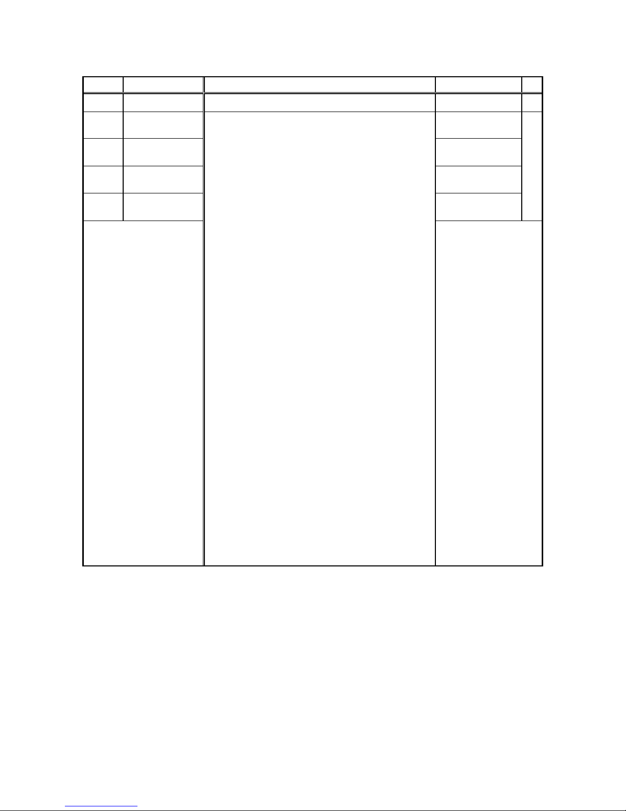
The multifunctional input of CC66-Z besides the input from a terminal block can be inputted from
CC-Link communication. Either can be chosen with the inverter setting parameter c-00. Refer to a
"CC66-Z communications protocol description" for the details of the multifunctional input by
communication.
Moreover, the multifunctional input signal of CC66-Z can be used as an input relay of the built-in PLC
function of VF66B inverter. For more information, refer to a "CC66-Z communications protocol description"
and the instruction manual of the inverter, and the description of VF66 PCTool.
Page 18
17
DANGER [Wiring]
Before wiring, make sure the power is OFF.
Failure to do so may cause an electric shock or a fire.
Substitution of Jumper socket is performed after certainly turning off an inverter.
Failure to do so may cause an electric shock, personal injury, equipment failure or malfunction.
CAUTION [Wiring]
G terminal and G2terminal are not connected to a grounding by any means.
Doing so may cause equipment failure or damage.
Never connect or allow contact between the PS and G terminals.
Doing so may cause equipment failure or damage.
4.2 Multifunction output
1. Connection with PLC (Source mode)
CC66-Z
Power source
(+24V max)
TB1
PLC input unit
COM
MO4
MO3
P
2. Connection with PLC (Sink mode)
CC66-Z
Power source
(+24V max)
TB1
PLC input unit
COM
MO4
MO3
P
3. Connection with Relay
CC66-Z
Power source
(+24V max)
TB1
COM
MO4
MO3
P
RY
RY
+
+
Figure 4.2 Multifunction output connections
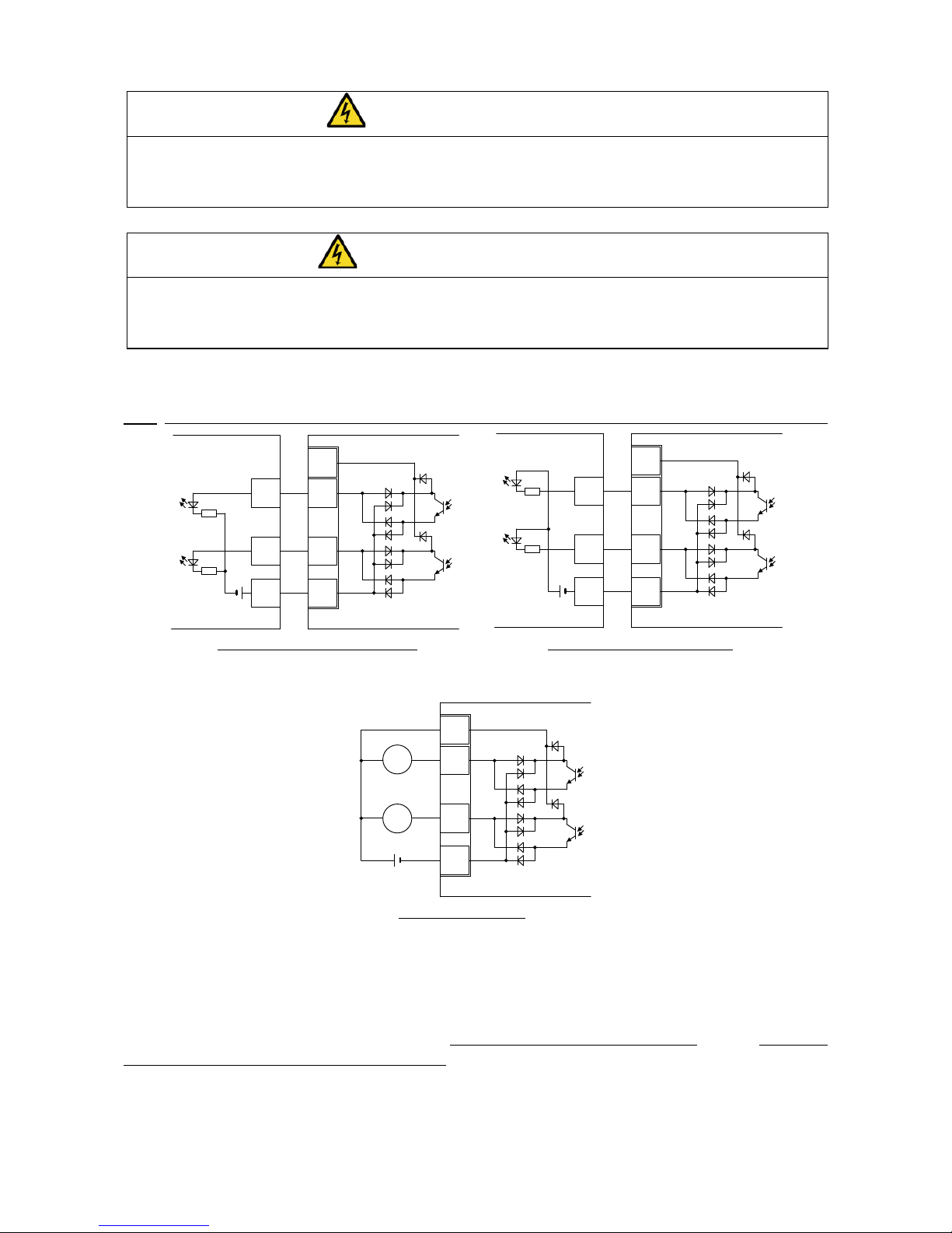
The CC66-Z can use the VF66B inverter multifunction output. The above figures show typical multifunction
output signal connection methods. Multifunction output is open corrector output of transistor. In order to use it,
DC power supply are required for the exterior. The maximum allowable voltage is 24V and the maximum
allowable current for any one terminal is 20mA. For more information about the functions of the individual
multifunction output terminals, please refer to the instruction manual of the inverter.
Page 19
18
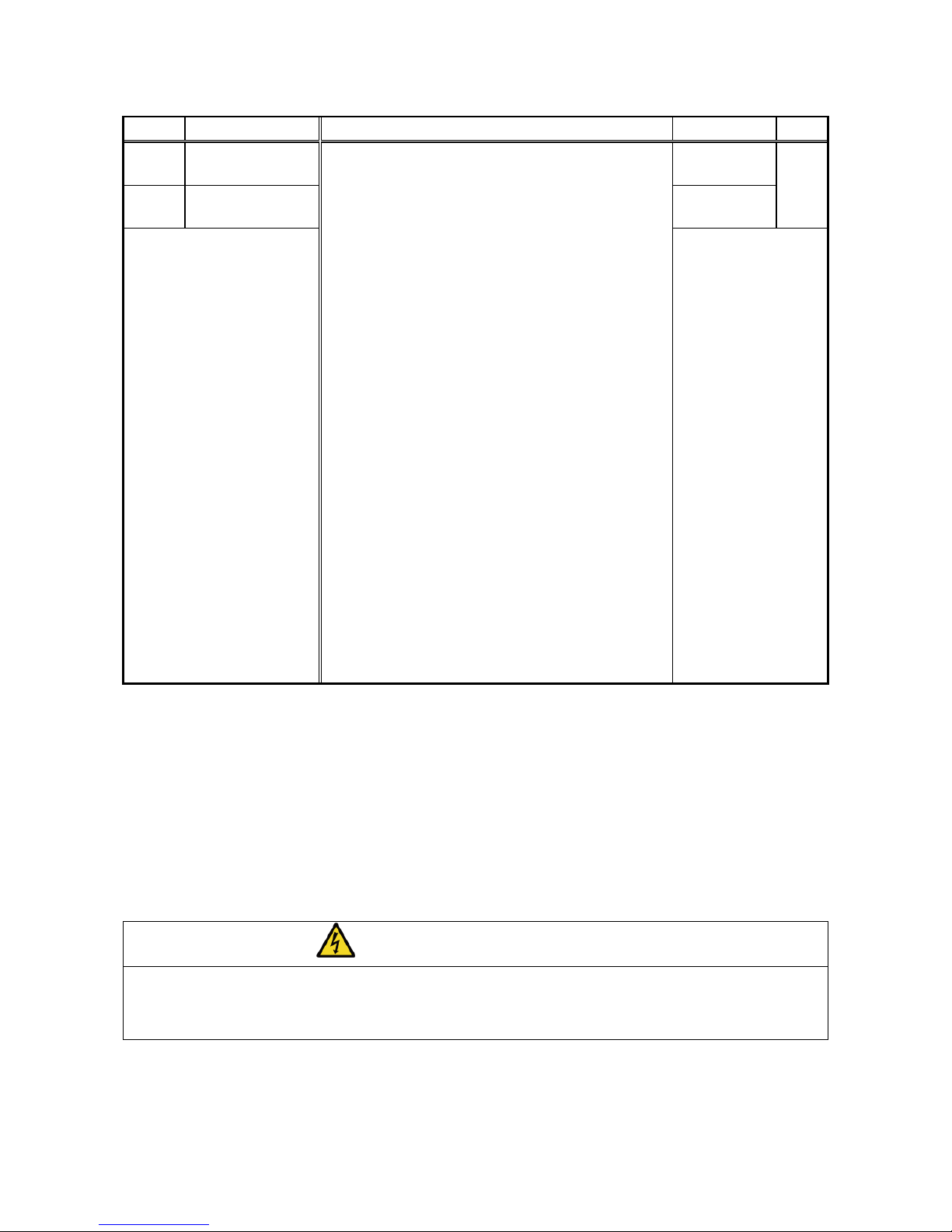
Multifunction output related inverter parameters
Display
Items
Item Selection
Default Data
Unit
H-02
Multifunction output
terminal (3)
function selection
0: not used
1: Frequency detection (1) (V/f mode)
( Frequency = detection setting )
Motor speed detection (1) (vector mode)
( Motor speed = detection setting )
2: Frequency detection (1) (V/f mode)
( Frequency ≧ detection setting )
Motor speed detection (1) (vector mode)
( Motor speed ≧ detection setting )
3: Frequency detection (1) (V/f mode)
( Frequency ≦ detection setting )
Motor speed detection (1) (vector mode)
( Motor speed ≦ detection setting )
4: Frequency detection (2) (V/f mode)
( Frequency = detection setting )
Motor speed detection (2) (vector mode)
( Motor speed = detection setting )
5: Frequency detection (2) (V/f mode)
( Frequency ≧ detection setting )
Motor speed detection (2) (vector mode)
( Motor speed ≧ detection setting )
6: Frequency detection (2) (V/f mode)
( Frequency ≦ detection setting )
Motor speed detection (2) (vector mode)
( Motor speed ≦ detection setting )
7: Reach setting
8: Torque detection
9: Torque detection (absolute value)
10: Power failure
11: Overload pre-alarm
12: Restart mode
13: In reverse operation
14: Protection operation code
15: not used
16: In operation
17: Extended schedule function(Usually, not set up)
18: Timer 1 setup time passes
19: Timer 2 setup time passes)
20: 2nd set-up block selected
21: Cooling fan failed
23: DB abnormal state
0:not used
-
H-03
Multifunction output
terminal (4)
function selection
1:Torque
detection
When connecting a PLC input unit outside, CC66-Z can choose a connection in sink mode and source mode.
Recommends using a twist line to a product line of PLC and CC66-Z. When connecting a relay externally, a coil
uses a relay of a D.C. operation (for example, OMRON: G7T-112S-DC24V etc.). Since CC66-Z builds in the
reflux diode which controls surge voltage, it certainly connects the + side terminal of external power source to
P terminal of a terminal block in CC66-Z.
The CC66-Z multifunction output signal can also be used as the VF66B inverter built-in PLC function output
relay. For more information, refer to a "CC66-Z communications protocol description" and the instruction
manual of the inverter, and the description of VF66 PCTool.
CAUTION [Wiring]
Before wiring, make sure the power is OFF.
Failure to do so may cause an electric shock or a fire.
COM terminal and G terminal in terminal block 1 are not connected to a grounding by any means.
Doing so may cause equipment failure or damage.
Page 20
19
5.1 Analog input (2)
The analog input (2) to the terminals on CC66-Z can be used as the input value to the rotation speed
command value (or frequency command value), torque command value, and built–in PLC function by analog
input (2) function.
For usage of analog input(2) function correctly, the correct VF66B inverter parameter setting as mentioned
below is required. Refer the instruction manual of the inverter together. Furthermore, for the built-in PLC
function, please refer VF66 PC Tool manual.
Before usage of analog input(2), please conduct the adjustment of gain as mentioned below.
Inverter setting parameter of analog input (2) input characteristics
Display
Item
Set-up range
(Item selection)
Default
Data
Unit
G-03
Analog input(2) characteristics
selection
0:0 to ±10V
1:0 to 10V
2:4 to 20mA
1
―
* If setting the torque command value as analog input (2), set this to “0”. Only the 0 to ±10V voltage input characteristic can
be used.
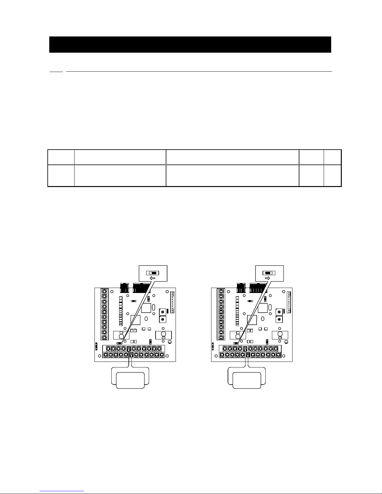
The analog signal input into analog input (2) should be connected between the [AIN2] and [G2] terminals of
the CC66-Z terminal block TB1, as shown in the following figures. The input analog signal characteristics can
be chosen as either “voltage input 0 to ±10V”, “voltage input 0 to 10V” or “current input 4 to 20mA”, as shown
in the above table. Choose an appropriate setting that matches the characteristics of the input signal. Also set
the SW1 switch as shown in the following figures.
AIN2
G2
CC66-Z
TB1
Variable
voltage
source
SW1
O
N
OFF
SW1
AIN2
G2
CC66-Z
TB1
Variable
current
source
SW1
O
N
ON
SW1
(a) Voltage input (b) Current input
Figure 5.1 Connection of analog input (2)
Chapter 5 Analog input/output function
Page 21
20
5.2 Analog input (2) input gain and offset adjustment
Before usage of analog input (2), gain and offset adjustment are required. Adjustment is conducted under
the temperature about 25℃.
Gain offset of an analog input (2) is adjusted after adjustment of gain offset of the analog input (1) of the
main part of VF66 inverter. Refer to the instruction manual of the inverter for the adjustment method of gain
offset of an analog input (1). Since it is adjusted at the time of factory shipments, it is not usually necessary to
adjust gain offset of an analog input (1).
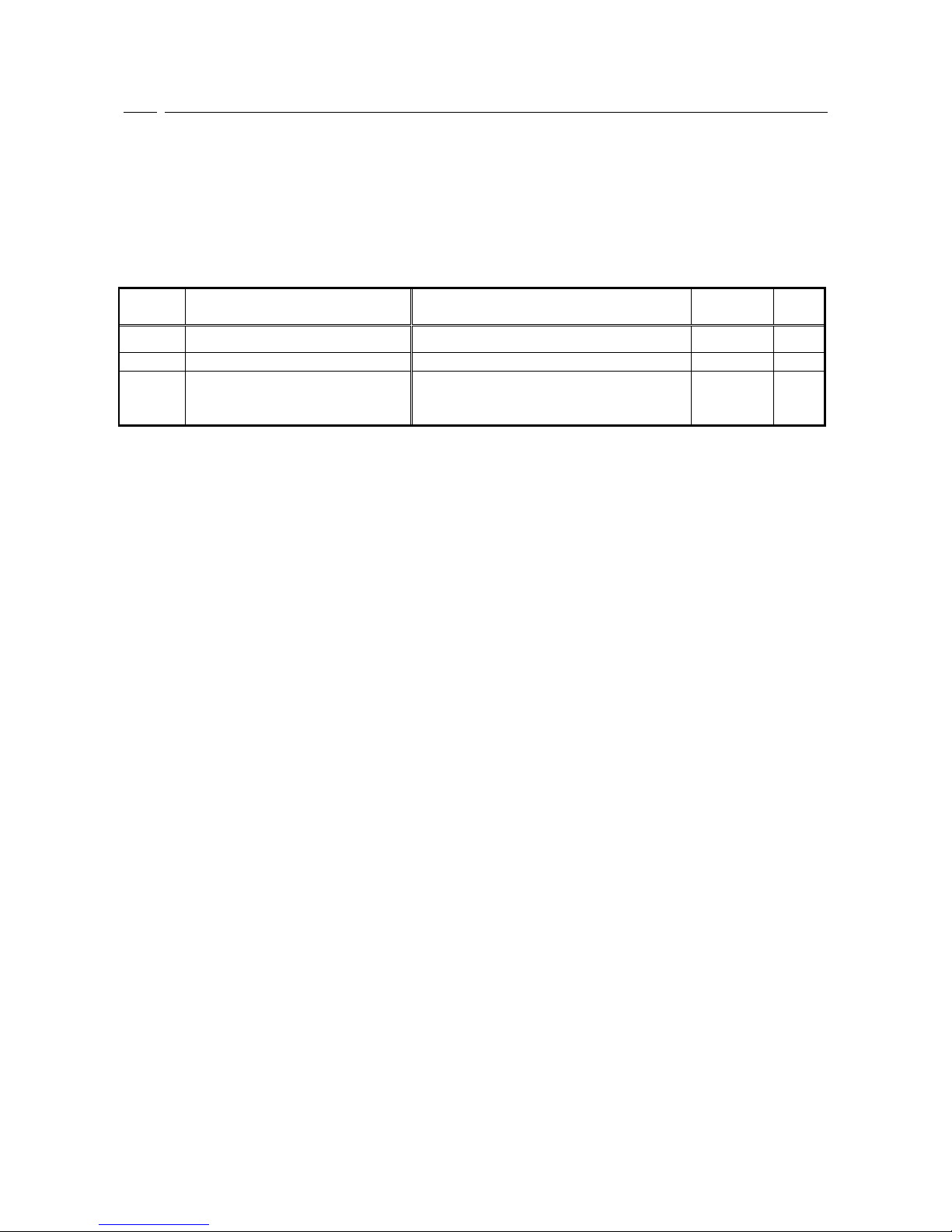
Inverter setting parameter related to analog input(2) gain and offset adjustment
Display
Items
Set-up range
(Item selection)
Default
Data
Unit
L-05
Analog input(2) gain
50.00 to 150.00
100.00
%
L-06
Analog input(2) offset
-50.00 to 50.00
0.00
%
S-08
Analog input(2) adjust
1. Analog input(2) offset adjustment
Input the analog(2) voltage x 1000
Analog input(2) gain adjustment
-
-
Page 22
21
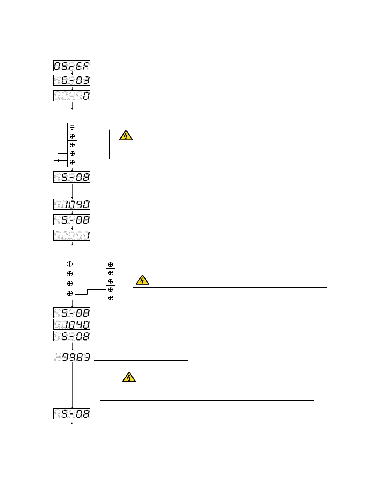
(1)Input characteristics “0 to ±10V” or “0 to 10V”
Press [MONI/FNC]key to turn on FNC (function selection) mode (LED-FNC will be lit).
Use [↑][↓]keys to select「G-03」and press [SET] key to confirm it.
Use [JOG/→] [↑][↓]keys to input「1040」and press[SET]key to confirm it.
Use [JOG/→]key to shift the digit to right, and [↑][↓]keys to input “0” and press [SET]keys to
confirm it.
Turn Off the inverter, open the front cover, and short circuit between [AIN2] [G] [G2] terminal
on the terminal block <TB1> of the <CC66-Z>.
After power is ON, press [MONI/FNC]key to turn on FNC (function selection) mode. (LED-FNC
will be lit). Use[JOG/→] [↑][↓]keys to select「S-08」,and press [SET] key to confirm it.
「S-08」will appear again, press[SET]key to confirm.
Use [JOG/→] and [↑][↓]keys to select “1” and press[SET]key to confirm it.
Turn OFF the inverter, open the front cover, and short circuit between [AIN2] on the
terminal block <TB1> of the <CC66-Z> and [+10] on the terminal block <TB1> of
the control board <VFC66-Z>. Remain short circuited terminals between [G] and [G2]
of the <CC66-Z>.
CAUTION[Short-Circuit of terminals]
● Before short circuiting terminals, please be sure to turn OFF the inverter.
There is a risk of electrical shock.
・After power is ON, press[MONI/FNC]key to turn on FNC(function selection)mode.(LED-FNC
will be lit)then, use [JOG/→] [↑][↓]keys to select「S-08」and press [SET]key to confirm.
・Use [JOG/→] [↑][↓]keys to change numbers, Input 「1040」and press [SET]key to confirm.
・「S-08」will appear again, press [SET]key to confirm.
If「S-08」appears again, analog input (2) gain (L-05) and analog input (2) offset (L-06) will
be changed automatically. Press [MONI/FNC] Key to indicate monitor items.
CAUTION[Voltage measurement]
● When the voltage between the terminals is measured, please be sure not to touch wirings
or terminals.
There is a risk of electrical shock.
<CC66-Z>
terminal block
G
・・・・・・・・
・・
AIN2
G2
When adjustment is done, turn OFF the inverter, open the front cover and remove the short circuit wirings
installed between terminals, [AIN2] of the <CC66-Z> and [+10] of the control board <VFC66-Z>, as well as
[G] and [G2] on the <CC66-Z>.
Measure the voltage between the <CC66-Z> terminals [AIN2] and [G] with a tester and enter
the 1000times of the measured value. If measurement is not available, the value”9930” can be
used. However accuracy is inferior.
CAUTION [Short-Circuit of terminals]
● Before short circuiting terminals, please be sure to turn OFF the inverter.
There is a risk of electrical shock.
<CC66-Z>
terminal block
G
・・・・・・・・
・・
AIN2
G2
GND
AIN1
<VFC66-Z>
terminal block
AOT1
+10
Page 23
22
(2)Input characteristics of “4 to 20mA”
※Conduct this after adjustment of aforementioned “(1) if the input characteristics is 0 to ±10V or 0 to
10V”
Press [MONI/FNC]key to turn on, FNC(function selection)mode.(LED-FNC will be lid)
Turn off the inverter, open the front cover and connect the current power between
terminals [AIN2] And [G2] on the terminal block <TB1> of the <CC66-Z>.
CAUTION [Connection of current power]
● Before connecting current power, please be sure to turn OFF the inverter.
There is a risk of electrical shock.
● Please be sure to turn OFF the inverter before switching a switch.
There is a risk of electrical shock.
G2
AIN2
<CC66-Z>
terminal board
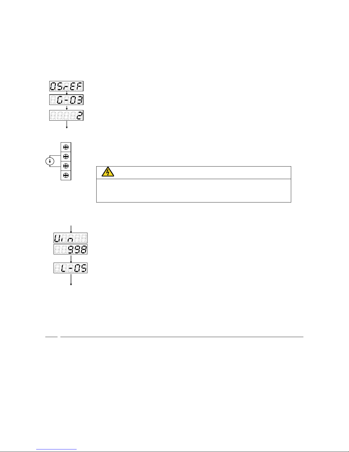
・After power is ON, select「2」in「G-16」and use monitor item[↑][↓]keys to select「Vin」
input voltage of analog input(2) appears in 「Vin」.
・Turn the current power ON and input 20mA to [AIN2] terminal.
・A number will be displayed.
Turn the SW1 ON (terminal block side) while the power of inverter is OFF.
・Adjust the value「L-05」so that the value of monitor item 「Vin」 becomes 「10.00」.
When adjustment is done, remove the current power.
Use [↑][↓]keys to select「G-03」,press [SET]key to confirm.
Use [JOG/→][↑][↓]key to change the numbers and input「2(4 to 20mA)」and press[SET]key
to confirm it.
5.3 Analog input (2) usage instructions
Before using the analog input (2) function, perform gain and offset adjustment as described in the preceding
section.
Through the analog input (2), the input analog signal can be set to be the rotation speed command value (or
frequency command value), torque command value or built-in PLC input value. The following explanation is
for when it is set as the rotation speed command value or the torque command value. For instructions when
using it as the input value to the built-in PLC, refer to the VF66 PCTool manual.
Page 24
23
(1)When using the input as a rotation speed command value
When using the analog input as a rotation speed command value, the inverter configuration parameters
shown in the following table must be set.
Analog input rotation speed command settings
Display
Items
Set-up Range (Item Selection)
Default
Data
Unit
b-10
Rotation speed commanding input
place selection
0: Coupled with b-09
1: Analog input (1) [VFC66-Z terminal block AIN1]
2: Console [SET66-Z]
3: Digital communication option
4: Analog input (2) [Optional terminal block AIN2]
5: <BCD66-Z>
6: Analog input (3) [Optional terminal block AIN3]
7: Built-in PLC function output
0
―
G-04
Analog input (2) rotation speed
upper limit
[Absolute value of analog input (2) rotation speed lower
limit (G-05) ] to [100.0]
(*)
100.0
%
(*)
G-05
Analog input (2) rotation speed
lower limit
-[Analog input (2) rotation speed upper limit (G-04)] to
[Analog input (2) rotation speed upper limit (G-04)]
(*)
0.0
%
(*)
(*) This is set as a percentage with respect to the maximum rotation speed (configuration parameter A-00).
For more information about configuration parameter A-00, please refer to the instruction manual of the inverter.
- Set b-10 to “4”.
- Set G-03 (described in section 5.1) to a set value that matches the input signal characteristics.
・In the case of voltage input of 0 to ±10V
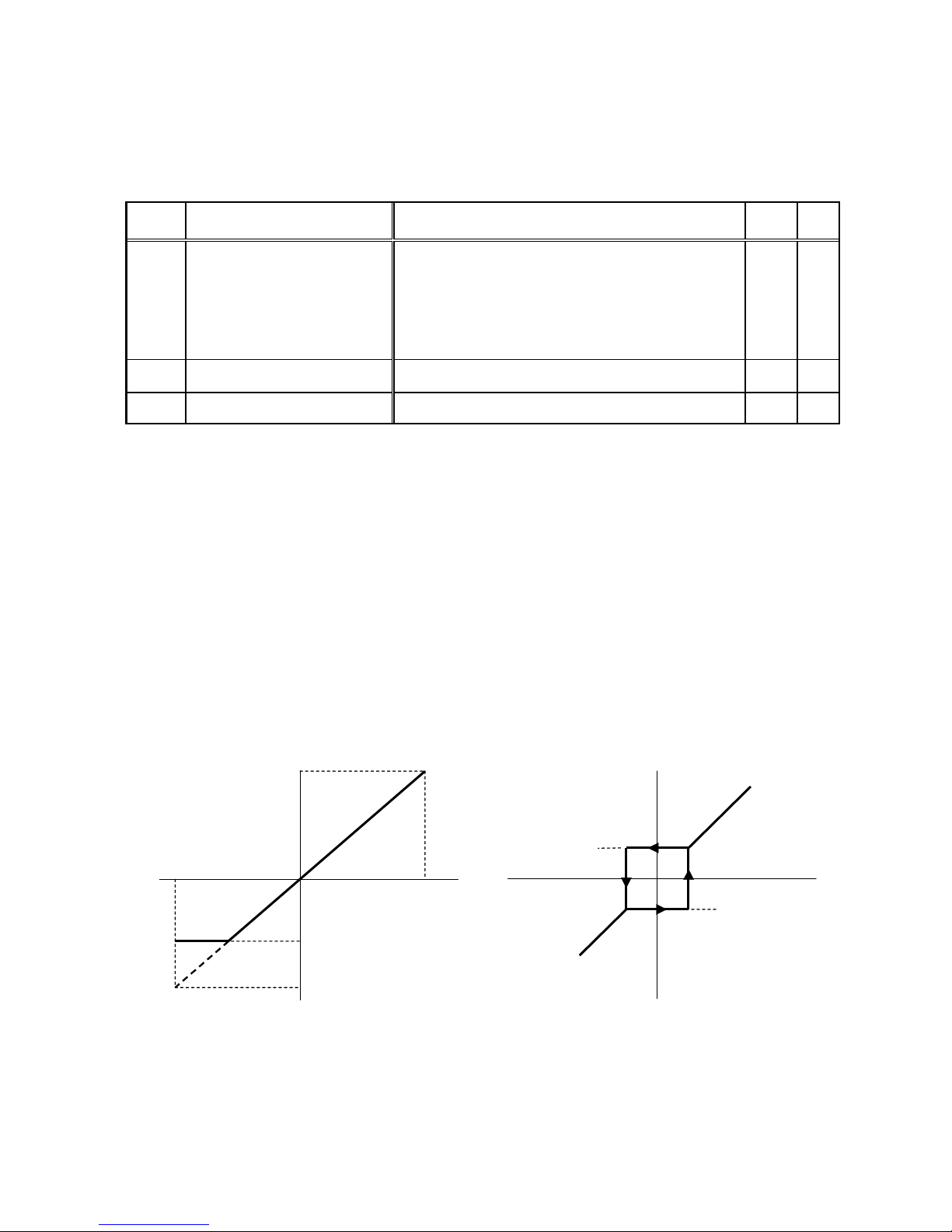
The rotational direction can be reversed by setting the command input voltage to a negative value. The
rotation speed command value is set as the analog input (2) rotation speed upper limit (G-04) when the input
is +10V. When the input is -10V, it is set as the negative value of the analog input (2) rotation speed upper
limit (G-04). However, it is possible to set a lower limit by setting the analog input (2) rotation speed lower
limit (G-05). (Figure 5.2, left) If the minimum rotation speed (A-01) is other than “0”, the rotation speed
command absolute value is controlled to prevent falling below the minimum speed. In this case, when the
command input voltage is around the 0V range, its behavior shows hysteresis characteristics (It will run
forward if started in the forward direction and will run in the minimum reverse speed if started in the reverse
direction) as shown in the right side of Figure 5.2.
Input voltage
+10V
-10V
Speed command
G-04
G-05 0 G-04×(-1)
Input characteristics (0 to ±10V)
Speed command
A-01
A-01×(-1)
Input voltage
Minimum rotation speed hysteresis characteristics when
near 0V
Figure 5.2 Speed command characteristics with voltage input of 0 to ±10V
Page 25
24
・In the case of voltage input of 0 to 10V
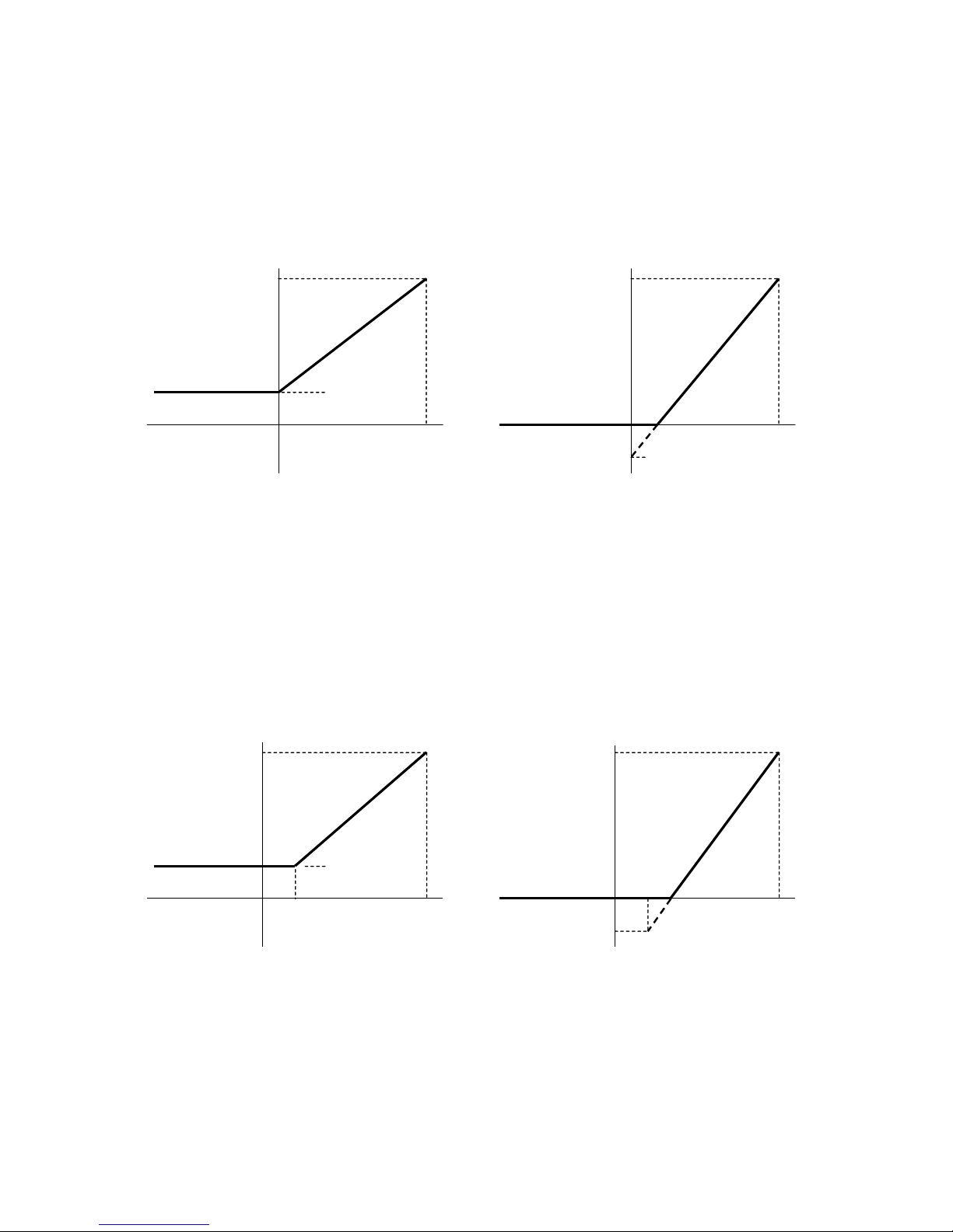
The rotation speed command value is set as the analog input (2) rotation speed lower limit (G-05) when the
input is 0V. When the input is 10V, it is set as the analog input (2) rotation speed upper limit (G-04). However,
this will be set to “0” if the analog input (2) rotation speed lower limit (G-05) has a negative value. (Figure 5.3)
If the minimum rotation speed (A-01) is other than “0”, the rotation speed command absolute value is
controlled to prevent falling below the minimum speed. As a speed command, this only allows forward
operation. For reverse operation, a reverse operation command should be used.
G-05
G-04
10V
0V
Input voltage
Speed command
Input characteristics when the analog input (2) rotation
speed lower limit (G-05) is positive (0 to 10V)
G-05
G-04
10V
0V
Input voltage
Speed command
Input characteristics when the analog input (2) rotation
speed lower limit (G-05) is negative (0 to 10V)
Figure 5.3 Speed command characteristics with voltage input of 0 to 10V
・In the case of current input of 4 to 20mA
The rotation speed command value is set as the analog input (2) rotation speed lower limit (G-05) when the
input is 4mA. When the input is 20mA, it is set as the analog input (2) rotation speed upper limit (G-04).
However, this will be set to “0” if the analog input (2) rotation speed lower limit (G-05) has a negative value.
(Figure 5.4) If the minimum rotation speed (A-01) is other than “0”, the rotation speed command absolute
value is controlled to prevent falling below the minimum speed. As a speed command, this only allows
forward operation. For reverse operation, a reverse operation command should be used.
G-05
G-0
20mA
4mA
Input current
Speed
command
Input characteristics when the analog input (2) rotation
speed lower limit (G-05) is positive (4 to 20mA)
G-05
G-0
20mA
4mA
Input current
Speed
command
Input characteristics when the analog input (2) rotation
speed lower limit (G-05) is negative (4 to 20mA)
Figure 5.4 Speed command characteristics with current input of 4 to 20mA
Page 26
25
(2)When using the input as a torque command value
When using the analog input as a torque command value, the inverter configuration parameters shown in
the following table must be set.
* Torque command is disabled in V/f mode.
* The 4 to 20mA current input characteristic cannot be used for the torque command value. Only the 0
to ±10V voltage input characteristic can be used.
Inverter configuration parameters related to analog input torque command
Display
Items
Set-up Range (Item Selection)
Default
Data
Unit
i-08
Torque command input place
selection
0: Analog input (1) [VFC66-Z terminal block AIN1]
1: Analog input (2) [Optional terminal block AIN2]
2: Digital communication option
3: Built-in PLC function output
1
―
i-09
Analog input torque command
gain
50.0 to 200.0
150.0
%
・Set i-08 to “1”.
・Set G-03 (described in section 5.1) to “0”. Only the 0 to ±10V
voltage input characteristic can be used.
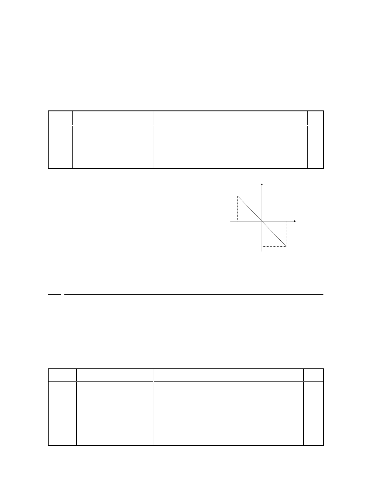
The torque command value is set as the negative value of the
analog input torque gain (i-09) when the input is +10V. When the
input is -10V, it is set as the positive value of the analog input
torque gain (i-09). (Figure 5.5)
(i-09)
-(i-09)
10V
-10V
Input signal[V]
Torque command[%]
Figure 5.5 Analog input torque command
characteristic
5.4 Analog output (2)
By analog output (2) function, output voltage of inverter, rotation speed and internal variable of output of
built-in PLC function are output as analog signal on PC board of CC66-Z. An analog signal is outputted
between "AOT2" and "G2" of terminal block TB1. Analog output characteristic output by analog output (2) is
“voltage output 0 to ±10V”. Please set the characteristic by setting parameter G-09. Please refer to the
instruction manual of the inverter with this manual. For built-in PLC function, please refer to the operation
manual about “VF66 PC Tool”.
Please adjust analog gain and offset before using analog output (2) function.
Analog output setting
Display
Items
Set-up Range (Item Selection)
Default
Data
Unit
G-09
Analog output(2) characteristic
selection
0:Output voltage
1:Output current
2:Torque output(V/f mode)
Torque command(vector mode)
3:Output frequency(V/f mode)
Motor rotation speed(vector mode)
4:Output frequency command(V/f mode)
Motor rotation speed command(vector mode)
5:Built-in PLC output
6:Calibration
7:Internal monitor
1
-
Page 27
26
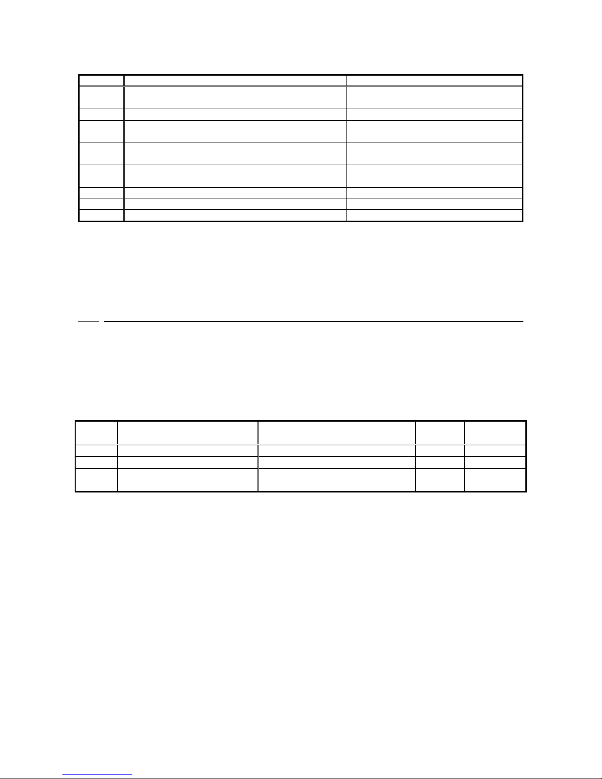
Analog output selected by G-09
G-09
Selection items
Output voltage
0
Output voltage
7.5V/200V(200V class)
7.5V/400V(400V class)
1
Output current
5V/inverter rated current
2
Torque output(V/f mode)
Torque command(vector mode)
5V/100%
3
Output frequency(V/f mode)
Motor rotation speed(vector mode)
10V/maximum frequency(A-00)
10V/maximum rotation speed (A-00)
4
Frequency command(V/f mode)
(*1)
Motor rotation speed(vector mode)
(*1)
10V/maximum frequency(A-00)
10V/maximum rotation speed (A-00)
5
Built-in PLC output
(*2)
5V/20000 (100%)
(*2)
6
Calibration
5V
7
Internal monitor
―
(*1)It is value after acceleration/deceleration control. For more information, please refer to the instruction manual of
the
inverter.
(*2)When built-in PLC output is selected, the value of output resistor “o00009”is output at the rate of 5V/20000.
For more information, please refer to the operation manual about “VF66 PC Tool”.
5.5 Analog output (2) gain offset adjustment
Before usage of analog output (2), please adjust gain offset under the condition of 25℃.
Analog output (2) gain offset adjustment is conducted after the VF66B inverter analog input (1) gain offset
adjustment. As to adjustment of analog input (1) gain offset, please refer the VF66B inverter instruction
manual. Analog input (1) gain offset is adjusted when the inverter is shipped from our works, therefore
analog input (1) gain offset is not necessary to adjust.
Inverter setting parameter related to analog output gain offset adjustment
Display
Items
Set-up Range (Item Selection)
Default
Data
Unit
L-09
Analog output(2) gain
50.0 to 150.0
100.0
%
L-10
Analog output(2) offset
-50.0 to 50.0
0.0
%
S-09
Analog output (2) adjust
1: Analog output (2) offset adjustment
2: Analog output (2) gain adjustment
-
-
Page 28
27
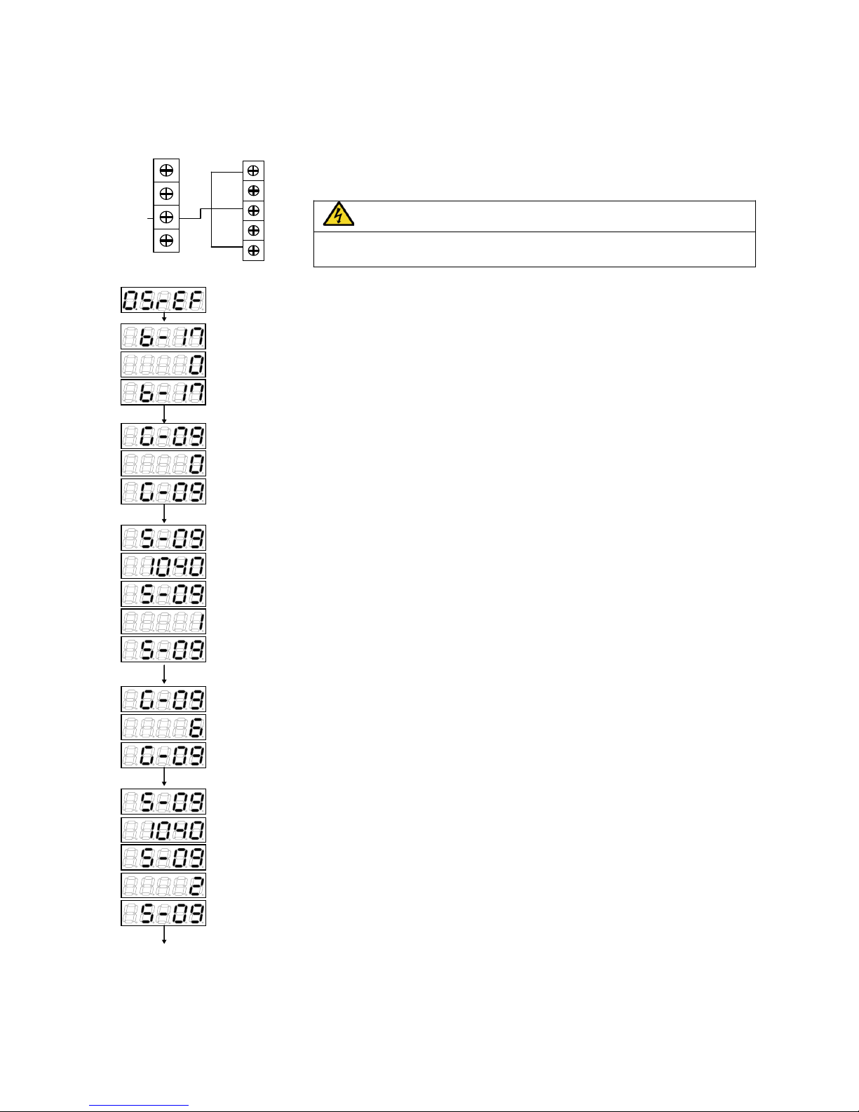
・Adjustment of offset and gain of analog output (2)
Turn OFF the inverter, open the front cover, and short circuit between terminals
[AOT2] on the terminal block <TB1> of the <CC66-Z> and [AIN1] on the
terminal block <TB1> of the control board <VFC66-Z> and so as [G] and [G2]
on the terminal block <TB1> of the <CC66-Z>.
CAUTION [Short circuiting of terminals]
● Before short circuiting terminals, please be sure to turn OFF the inverter.
There is a risk of electrical shock.
After power is ON, press [MONI/FNC] key to turn on FNC (function selection) mode.
(LED-FNC will be lit).
・Use[JOG/→] [↑][↓]keys to select「S-09」and press [SET]key to confirm it.
・Use[JOG/→] [↑][↓]keys to input「1040」and press [SET]key to confirm it.
・「S-09」will appear again, press [SET]key to confirm it.
・Use [JOG/→] [↑][↓]keys to input “1” and press [SET]key to confirm it.
・「 S-09」will appear again.
・After power is ON, press [MONI/FNC] key to turn on FNC (function selection) mode.
(LED-FNC will be lit). Use [JOG/→] [↑][↓] keys to select “b-17” then press [SET] to confirm
it.
・Use [JOG/→] [↑][↓]keys to input “0” and press[SET]key to confirm it.
・「b-17」appears again.
・Use [JOG/→] [↑][↓]keys to select「G-09」and press [SET]key to confirm it.
・Use [JOG/→] [↑][↓]keys to input “0” and press [SET]key to confirm it.
・「G-09」will appear again.
・Use [JOG/→] [↑][↓]keys to select「G-09」and press [SET]key to confirm it.
・Use [JOG/→] [↑][↓]keys to input “6” and press[SET]key to confirm it.
・「G-09」will appear again.
・Use [JOG/→] [↑][↓]keys to select「S-09」and press[SET]key to confirm it.
・Use [JOG/→] [↑][↓]keys to input「1040」and press [SET]key to confirm it
・「S-09」will appear again and press [SET]key to confirm it.
・Use [JOG/→] [↑][↓]keys to input “2” and press [SET]key to confirm it.
・If “S-09” appears again, analog output (2) gain (L-09) and analog output (2) offset (L-10)
will be changed automatically.
・Press [MONI/FNC] to indicate monitor items.
When adjustment is done, turn OFF the inverter, open the front cover, and remove the short circuit wirings
installed between terminals [AOT2] on the <CC66-Z> and [AIN1] on the control board <VFC66-Z>, as well as
[G] and [G2] on the <CC66-Z>. Reset the setting of [G-09] and [b-17].
・ ・ ・ ・ ・
・ ・ ・ ・ ・
<CC66-Z>
terminal block
G
AOT2
G2
GND
AIN1
<VFC66-Z>
terminal block
AOT1
+10
Page 29
28
Chapter 6 PG input/output function
PG input/output functionality is used when driving a motor from the signal which detected the magnetic pole
location and velocity of the rotor by the sensor (PG). PG is a correspondence only a complementary output
with 12V power source. The instruction manual of the inverter is referred to for a selection in PG mode, and
an inverter mode change.
6.1 PG input signal
In order to use PG input/output functiona, it is necessary to set correctly the inverter setups parameter
shown in the following table according to the operation mode of an inverter, and PG specification to be used.
Please also refer to the instruction manual of the inverter collectively.
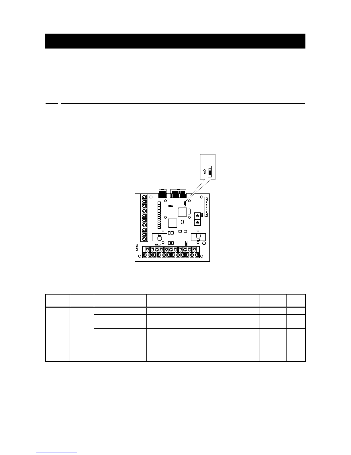
※When switch SW2 on CC66-Z is ON, the input of PG signal is effective.
CC66-Z
TB1
SW2
ON
SW2
ON
Figure 6.1 PG signal input switching
The inverter setups parameter of PG input signal setups
Display
Item
Set-up range
(Item selection)
Set-up resolution
Default
Data
Unit
A-10
PG
Selection
V/f mode
(PG not used)
―
―
Induction motor
vector control mode
0: S-mode Sensor-less drive
1: V-mode with PG (AB phase input)
0
―
ED motor vector
control mode
0: S-mode Sensor-less drive
1: V-mode with PG (ABZ phase input)
(*1)
2: P-mode with PG (ABUVW phase input)
3:
RL-mode with resolver (resolution 10bit)
(*2)
4:
RH-mode with resolver (resolution 12bit)
(*2)
0
―
(*1)For special motors
(*2)An option is required
Page 30
29
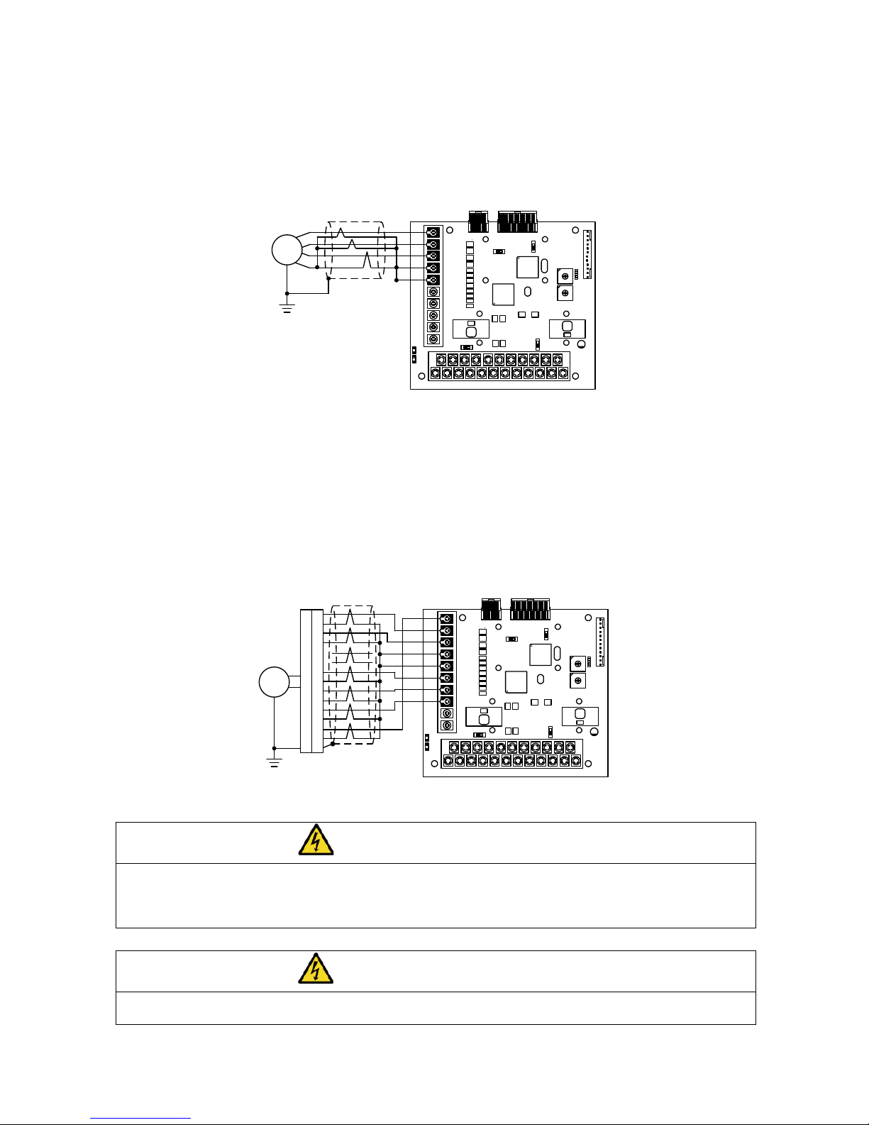
(1)In the case of induction motor vector control mode
Please set 1 as the setups parameter A-10 shown in the upper table, and as shown in Fig. 6.2, connect PG
wire to terminal block TB2 of CC66-Z. (Since it is not used, please do not connect U/Z, V, and W
termination of TB2.)
The recommendation cable of PG wire is CO-SPEV-SB(A)3Px0.5SQ (made by Hitachi Cable).
CC66-Z
TB1
+12
G
B
A
PG
A
B
F
E
Earth
Twisted pair shielding wire
CO-SPEV-SB(A)3P×0.5SQ
G
TB2
Figure 6.2 PG wire interconnection of an induction motor
(2)In the case of ED motor vector control mode
Please set 2 as the setups parameter A-10 shown in the upper table, and as shown in Fig. 6.3, connect PG
wire to terminal block TB2 of CC66-Z. (As the setting value of "1" for A-10 is used for a special motor, it
should not be selected for normal operation.)
The recommendation cable of PG wire is CO-SPEV-SB(A)7Px0.5SQ (made by Hitachi Cable). For ED motor PG
connection, straight plugs (MS3106B-20-29S) and cable clamps (MS3057-12A) (Japan Aviation Electronics
Industry, Ltd.) are required.
CC66-Z
TB1
A
B
C
D
F
G
H
J
K
L
M
T
S
R
N
A
B
C
D
F
G
H
J
K
L
M
T
S
R
N
TB2
+12
G
B
A
Earth
PG
U/Z
V
W
Twisted pair shielding wire
CO-SPEV-SB(A)7P×0.5SQ
MS3106B-20-29S
MS3057-12A
G
Figure 6.3 PG wire interconnection of an ED motor
DANGER [Wiring]
When wiring PG, an inverter power source is certainly turned off.
Failure to do so may cause an electric shock, personal injury, equipment failure or malfunction.
Never connect the G terminal to earth.
Doing so may cause equipment failure or damage.
DANGER [Switch]
Change of a switch is performed by certainly turning off an inverter.
Failure to do so may cause an electric shock, personal injury, equipment failure or malfunction.
Page 31
30
6.2 PG output signal
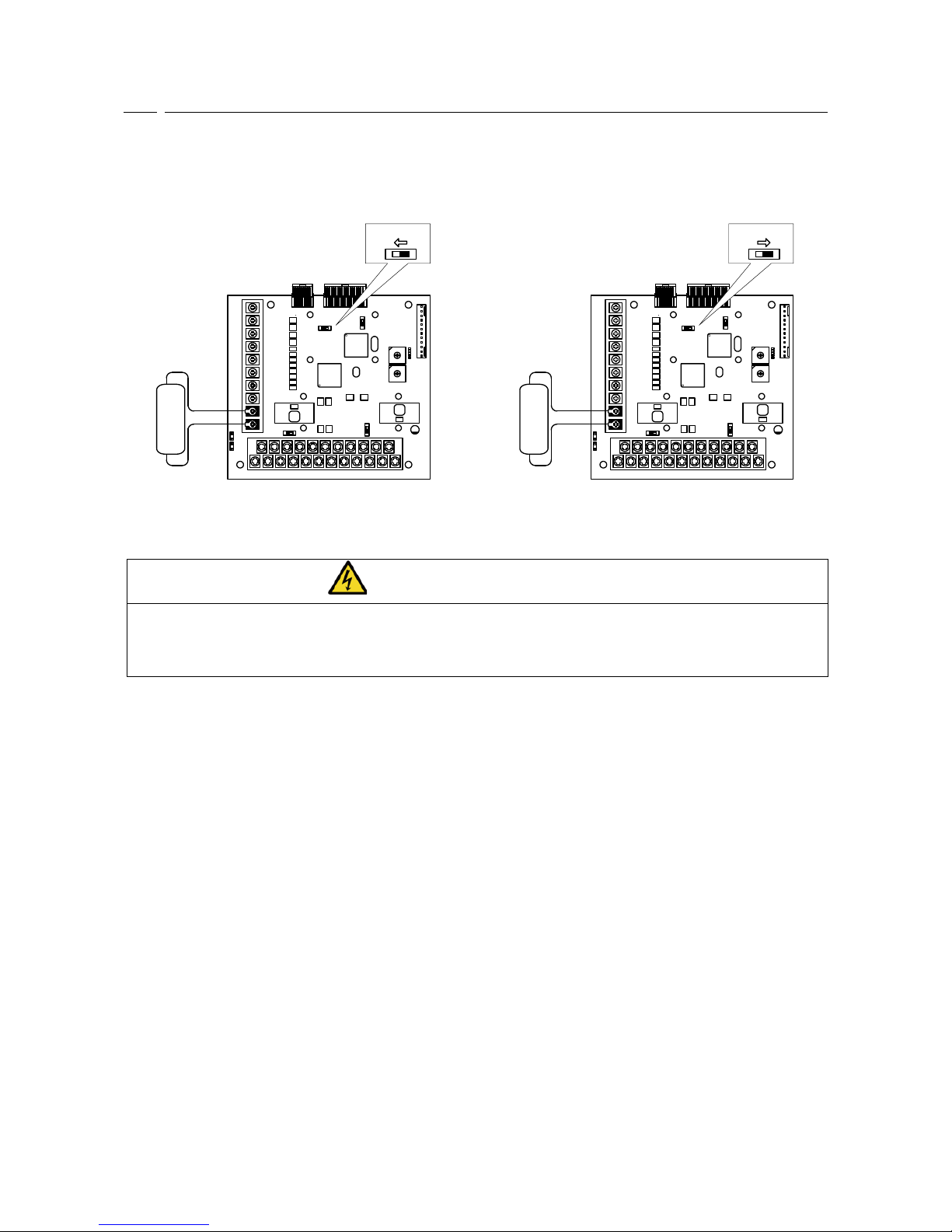
PG frequency dividing signal is outputted from A signal of PG input. Peak value is about 10V and duty1:1. If
SW4 of CC66-Z is switched to side of 3, 1 / 4PG frequency divided signal is outputted, and if SW4 is switched
to side of 1, 1 / 2PG frequency divided signal is outputted. Please switch according to a destination.
CC66-Z
TB1
TB2
PGOUT
G
Frequency
meter
SW4
1
SW4
1 3
CC66-Z
TB1
TB2
PGOUT
G
Frequency
meter
SW4
3
SW4
1 3
(a) 1 / 4PG frequency divided output (b) 1 / 2PG frequency divided output
Figure 6.4 PG signal output
DANGER [Wiring]
Before connecting anything to the terminals, please be sure to turn off the inverter.
Failure to do so may cause an electric shock, personal injury, equipment failure or malfunction.
Never connect the G terminal to earth.
Doing so may cause equipment failure or damage.
Page 32
31
Chapter 7 CC-Link communication function
7.1 Connection method of a communication cable
■ CC-Link connection
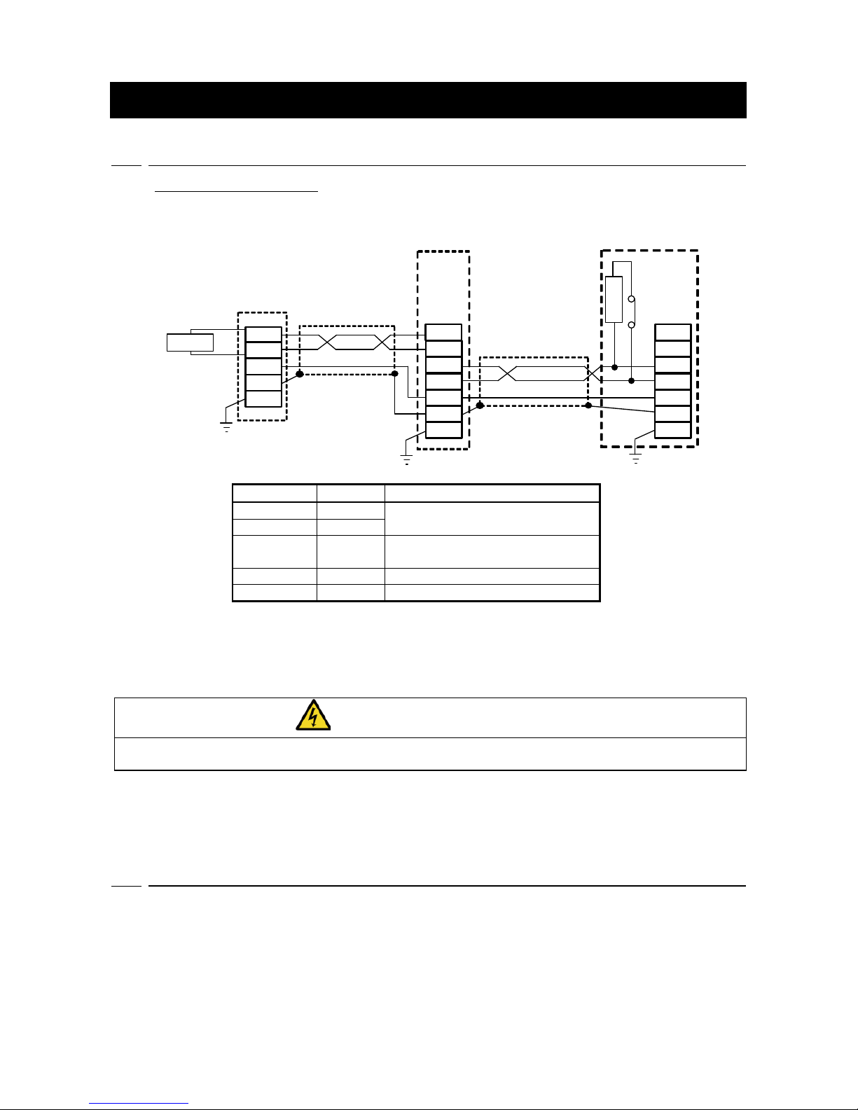
As shown in the following figure, the cable only for CC-Link is connected to the terminal stand (TB1)
of CC66-Z.
110Ω
110Ω
Terminator
Terminator
DA
DB
DG
SLD
FG
DA
DB
DG
SLD
FG
Master
station
CC66-Z
Cable only for CC-Link
CC66-Z
SW3
TB1
TB1
DA
DB
DA
DB
DG
SLD
FG
DA
DB
Cable only for CC-Link
Terminal block (TB1)
Cable coror
Name
Content
Blue
DA
Communication signal terminal
White
DB
Yellow
DG
Communication grounding
terminal
SLD
Communication shield terminal
FG
Protective ground terminal
* A shield line is connected to 0V (SG) terminal of the signal wire of a master station.
* When CC66-Z is an end station, a 100 ohms (more than 1W) terminator is connected among. When
CC66-Z becomes an end station, please turn ON SW3 and connect a terminator between terminal
DA-DB.
DANGER [Wiring]
Before connecting anything to the terminals, please be sure to turn off the inverter.
Failure to do so may cause an electric shock, personal injury, equipment failure or malfunction.
< The cable only for CC-Link >
Refer to the CC-Link association homepage for the cable only for CC-Link.
CC-Link association homepage: http://www.CC-Link.org/
7.2 Setup of CC-Link communication function
Through CC-Link communication, the CC66-Z can input operation and speed commands, torque commands
and multifunction input to the VF66B Inverter as well as monitor factors such as operating conditions,
protection conditions, current and voltage. It can also read and alter the inverter configuration data as well as
read the trace-back data, protection history and monitor data.
For information about CC-Link communication, please refer to the “CC66-Z Communication Protocol
Manual”. Furthermore, it can be used as the input/output signal of the VF66B Inverter built-in PLC function.
For information about the built-in PLC function, please refer to the VF66 PCTool manual.
Page 33

http://www.toyodenki.co.jp/
HEAD OFFICE: Tokyo Tatemono Yaesu Bldg, 1-4-16 Yaesu, Chuo-ku,
Tokyo, Japan ZIP CODE 103-0028
TEL: +81-3-5202-8132 - 6
FAX: +81-3-5202-8150
In addition, the contents of this the "operating manual" may be changed without a preliminary announcement by specification
change of a product etc. Please understand that it may differ from the contents of the "operating manual" enclosed by the
model of purchase, and the contents of the "operating manual" posted on our homepage.
Please have a look from our homepage about the newest "operating manual."
Contents of this manual are subject to change without notice.
TIM019[A]_20140624
 Loading...