

Page 1
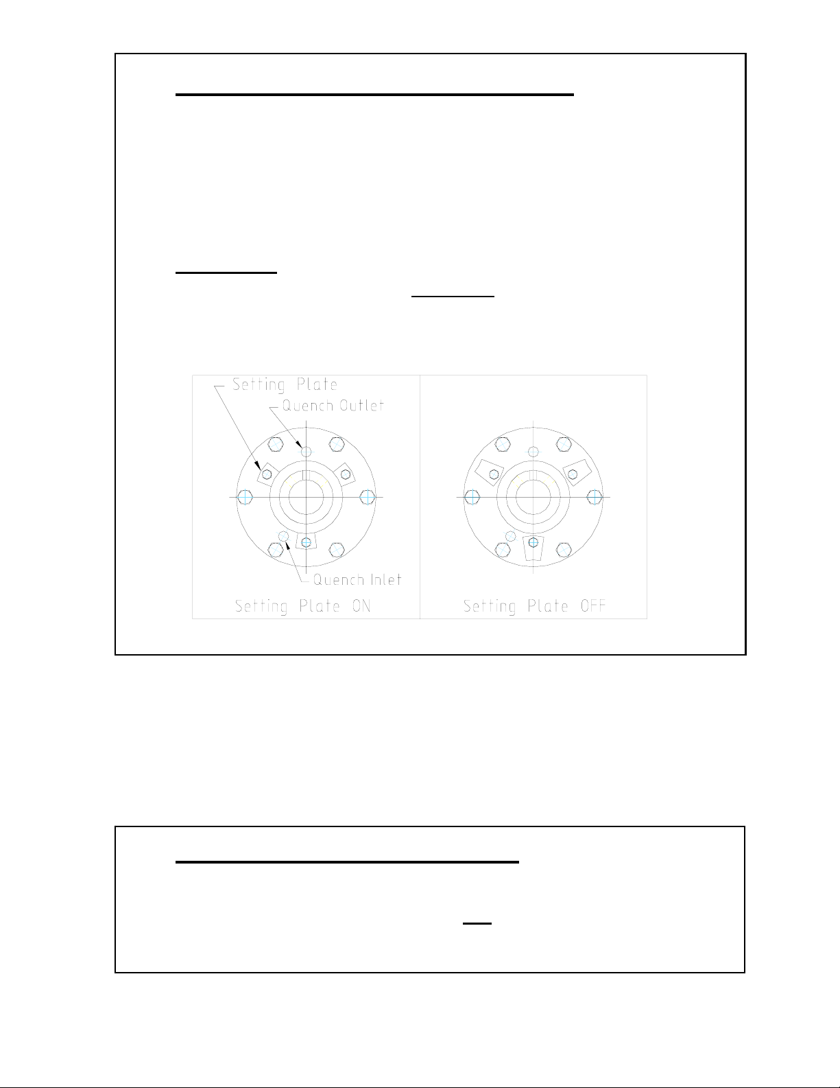
1. For Mechanical Seal Pumps
- See section 5.6.2 and 6.2.1 in manual.
- Toyo recommends a continuous clean water quench of ¼ - ½
gpm at maximum 5 psi (inlet is at bottom), if there is no quench
water never operate the pump dry.
Warning
Prior to pump start up REMOVE mechanical seal Setting
Plates (Qty. 3) installed for shipping.
Failure to do so can cause seal damage and leakage.
2. For Stuffing Box Pumps
- See section 5.6.2 and 6.2.2 in manual.
- Flush water must be turned ON
before pump is started.
Page 2

CUSTOMER: Industrial Pump Systems
PURCHASE ORDER: 9762
PUMP MODEL: DBH-100/75MD-ROH
PUMP SERIAL NUMBER: D-30051-52
TYPE DBH
HORIZONTAL SLURRY PUMPS
INSTALLATION,
OPERATION &
MAINTENANCE
INSTRUCTIONS
TOYO PUMPS NORTH AMERICA CORPORATION
2853 Douglas Road Telephone: (604) 298-1213
Burnaby, British Columbia Fax: (604) 298-7773
CANADA V5C 6H2 Email: [email protected]
Page 3
TOYO PUMPS NORTH AMERICA CORPORATION
INSTALLATION, OPERATION AND MAINTENANCE MANUAL
TITLE: DBH MAINTENANCE OPERATION AND
INSTALLATION MANUAL
PREPARED BY: KSH DATE: MAY 1 1997
APPROVED BY: SN DATE: SUPERSEDES:
EFFECTIVE: MAY 5 2005 PUMP SERIAL NUMBER:
DOCUMENT NO: TED-039 REV. NO: 10 PAGE 1 OF 80
1.0 TECHNICAL DATA SHEET
CUSTOMER : Industrial Pump Systems
LOCATION :
APPLICATION : Mine Dewatering
PUMP MODEL : DBH-100/75MD-HC-ROH
EQUIPMENT NUMBER :
TAG NUMBER :
PUMP SERIAL NUMBER : D-30051
METALLURGY : HCr
OPERATING CONDITIONS
FLOW (USGPM)
NORMAL : 600
MAX :
MIN :
TDH (FEET) : 420
SLURRY S.G. : 1.05
SOLIDS % BY VOLUME :
MAX. PARTICLE SIZE (IN.) : 0.63
TEMPERATURE °F : 60
pH : Neutral
PUMP DATA
PUMP SPEED (RPM) : 1780
IMPELLER DIA. (IN.) : 19.7
SEAL TYPE : SiC Mechanical Seal
BEARING FRAME : F500
ASSEMBLY WEIGHT : 2164 KG [4761 lb.]
FOR COMPLETE PUMP DATA SHEET SEE SECTION 10.0
Page 4
TOYO PUMPS NORTH AMERICA CORPORATION
INSTALLATION, OPERATION AND MAINTENANCE MANUAL
TITLE: DBH MAINTENANCE OPERATION AND
INSTALLATION MANUAL
PREPARED BY: KSH DATE: MAY 1 1997
APPROVED BY: SN DATE: SUPERSEDES:
EFFECTIVE: MAY 5 2005 PUMP SERIAL NUMBER:
DOCUMENT NO: TED-039 REV. NO: 10 PAGE 1 OF 80
1.0 TECHNICAL DATA SHEET
CUSTOMER : Industrial Pump Systems
LOCATION :
APPLICATION : Mine Dewatering
PUMP MODEL : DBH-100/75MD-HC-ROH
EQUIPMENT NUMBER :
TAG NUMBER :
PUMP SERIAL NUMBER : D-30052
METALLURGY : HCr
OPERATING CONDITIONS
FLOW (USGPM)
NORMAL : 600
MAX :
MIN :
TDH (FEET) : 420
SLURRY S.G. : 1.05
SOLIDS % BY VOLUME :
MAX. PARTICLE SIZE (IN.) : 0.63
TEMPERATURE °F : 60
pH : Neutral
PUMP DATA
PUMP SPEED (RPM) : 1780
IMPELLER DIA. (IN.) : 19.7
SEAL TYPE : SiC Mechanical Seal
BEARING FRAME : F500
ASSEMBLY WEIGHT : 2164 KG [4761 lb.]
FOR COMPLETE PUMP DATA SHEET SEE SECTION 10.0
Page 5

TOYO PUMPS NORTH AMERICA CORPORATION
INSTALLATION, OPERATION AND MAINTENANCE MANUAL
TITLE: DBH INSTALLATION OPERATION AND
MAINTENANCE MANUAL
PREPARED BY: KSH RELEASE DATE: MAY 1 1997
APPROVED BY: SN REVISION DATE: MAR 15 2007
SUPERSEDES: REVISED BY:
DOCUMENT NO:
TED-039
REV. NO: 10
SHEET 2 OF 80
1.1 CUSTOMER FILL IN DATA SHEET
START-UP OPERATING CONDITIONS
FLOW (USGPM) NORMAL : MAX. : MIN. :
DISCHARGE PRESSURE (PSI) :
SUCTION PRESSURE (PSI) : (IN.Hg):
SLURRY S.G. :
SOLIDS % BY VOLUME :
MAX. PARTICLE SIZE (IN.) :
TEMPERATURE :
pH :
START-UP PUMP DATA
PUMP SPEED (RPM) :
POWER DRAW (AMPS) :
OIL TEMPERATURE (°F) :
NOTES :
Page 6
TOYO PUMPS NORTH AMERICA CORPORATION
INSTALLATION, OPERATION AND MAINTENANCE MANUAL
TITLE: DBH INSTALLATION OPERATION AND
MAINTENANCE MANUAL
PREPARED BY: KSH RELEASE DATE: MAY 1 1997
APPROVED BY: SN REVISION DATE: MAR 15 2007
SUPERSEDES: REVISED BY:
DOCUMENT NO:
TED-039
REV. NO: 10 SHEET 3 OF 80
TABLE OF CONTENTS
SECTION 1.0 TECHNICAL DATA SHEET
1.1 CUSTOMER FILL IN DATA SHEET
SECTION 2.0 INTRODUCTION
SECTION 3.0 WARRANTIES
SECTION 4.0 SAFETY
SECTION 5.0 INSTALLATION
5.1 CHECK UPON ARRIVAL
5.2 STORAGE
5.2.1 NEW PUMP AND EQUIPMENT STORAGE
5.2.2 USED PUMP STORAGE
5.2.3 SPARE PARTS STORAGE
5.3 HANDLING
5.4 ALIGNMENT
5.5 MOUNTING
5.5.1 CONCRETE MOUNTING
5.5.2 STEEL FRAME MOUNTING
5.6 PIPING
5.6.1 SUCTION AND DISCHARGE
5.6.2 SEAL PIPING
5.7 POWER SUPPLY
Page 7

TOYO PUMPS NORTH AMERICA CORPORATION
INSTALLATION, OPERATION AND MAINTENANCE MANUAL
TITLE: DBH INSTALLATION OPERATION AND
MAINTENANCE MANUAL
PREPARED BY: KSH RELEASE DATE: MAY 1 1997
APPROVED BY: SN REVISION DATE: MAR 15 2007
SUPERSEDES: REVISED BY:
DOCUMENT NO:
TED-039
REV. NO: 10
SHEET 4 OF 80
TABLE OF CONTENTS (ctd)
SECTION 6.0 OPERATION
6.1 ROTATION
6.2 SHAFT SEAL
6.2.1 MECHANICAL SEAL
6.2.2 STUFFING BOX
6.2.3 CENTRIFUGAL SEAL
6.3 START UP
SECTION 7.0 MAINTENANCE
7.1 INSPECTION AND ADJUSTMENT FOR WEAR
7.1.1 GENERAL
7.1.2 IMPELLER CLEARANCE ADJUSTMENT
7.1.2.1 VISUAL INSPECTION
7.1.3 FRONT PULL OUT
7.1.4 BACK PULL OUT
7.1.5 IMPELLER REMOVAL
7.1.6 MECHANICAL SEAL INSPECTION
7.1.7 STUFFING BOX INSPECTION
7.1.7.1 LOW FLOW STUFFING BOX
7.1.7.2 FULL FLOW STUFFING BOX
7.1.8 BEARING CLEARANCE ADJUSTMENT
7.2 LUBRICATION
7.2.1 BEARING LUBRICATION
7.2.2 BEARING HOUSING SEAL LUBRICATION
7.3 TROUBLE SHOOTING
Page 8

TOYO PUMPS NORTH AMERICA CORPORATION
INSTALLATION, OPERATION AND MAINTENANCE MANUAL
TITLE: DBH INSTALLATION OPERATION AND
MAINTENANCE MANUAL
PREPARED BY: KSH RELEASE DATE: MAY 1 1997
APPROVED BY: SN REVISION DATE: MAR 15 2007
SUPERSEDES: REVISED BY:
DOCUMENT NO:
TED-039
REV. NO: 10
SHEET 5 OF 80
TABLE OF CONTENTS (ctd)
SECTION 8.0 BEARING FRAME ASSEMBLY
8.1 SHAFT PRE-ASSEMBLY
8.2 BEARING END COVER PRE-ASSEMBLY
8.3 BEARING HOUSING ASSEMBLY
8.4 BEARING CLEARANCE SETTING
8.5 SHAFT SLEEVE, FLINGER AND HARDWARE ASSEMBLY
8.6 FRAME ADAPTER, FEET AND BASE PLATE ASSEMBLY
8.7 BEARING SIDE LINER, MECHANICAL SEALS AND STUFFING BOX
8.7.1 BEARING SIDE LINER ASSEMBLY
8.7.2 MECHANICAL SEAL INSTALLATION
8.7.3 LOW FLOW STUFFING BOX
8.7.4 FULL FLOW STUFFING BOX
8.7.5 LOW FLOW WATER INLET
8.7.6 FULL FLOW WATER INLET
8.7.7 STUFFING BOX INSTALLATION
SECTION 9.0 WET END ASSEMBLY
9.1 IMPELLER INSTALLATION
9.2 CASING ASSEMBLY
9.2.1 WEAR RING INSTALLATION
9.2.2 SUCTION THROAT LINER INSTALLATION
9.2.3 CASING INSTALLATION
Page 9
TOYO PUMPS NORTH AMERICA CORPORATION
INSTALLATION, OPERATION AND MAINTENANCE MANUAL
TITLE: DBH INSTALLATION OPERATION AND
MAINTENANCE MANUAL
PREPARED BY: KSH RELEASE DATE: MAY 1 1997
APPROVED BY: SN REVISION DATE: MAR 15 2007
SUPERSEDES: REVISED BY:
DOCUMENT NO:
TED-039
REV. NO: 10 SHEET 6 OF 80
TABLE OF CONTENTS (ctd)
SECTION 10.0 APPENDIX
10.1 LUBRICATION GUIDE
10.2 BOLT TORQUE TABLE (A3670)
10.3 TOOL LIST (A3703)
10.4 TYPICAL PUMP SPEED vs. TORQUE CURVE (A3080)
10.5 WEIGHTS AND DIMENSION TABLE (B3497-B3501)
10.6 CENTRIFUGAL PUMP DATA SHEET
10.7 PUMP PERFORMANCE DATA
10.7.1 CERTIFIED PUMP TEST REPORT (IF APPLICABLE)
10.8 BEARING FRAME ASSEMBLY DRAWING
10.9 PUMP ASSEMBLY DRAWING
10.10 STUFFING BOX ASSEMBLY DRAWING (IF APPLICABLE)
10.11 PUMP GENERAL ARRANGEMENT DRAWING
10.12 MECHANICAL SEAL INSTRUCTIONS (IF APPLICABLE)
10.12.1 MECHANICAL SEAL ASSEMBLY DRAWING (IF APPLICABLE)
10.13 PARTS LIST
10.14 AUXILIARY EQUIPMENT
10.14.1 ELECTRIC MOTOR INFORMATION (IF APPLICABLE)
10.14.2 COUPLING INFORMATION (IF APPLICABLE)
10.14.3 GEAR REDUCER INFORMATION (IF APPLICABLE)
10.7.2 PUMP PERFORMANCE CURVE (IF APPLICABLE)
10.7.3 HYDROSTATIC PRESSURE TEST CERTIFICATE (IF APPLICABLE)
Page 10

TOYO PUMPS NORTH AMERICA CORPORATION
INSTALLATION, OPERATION AND MAINTENANCE MANUAL
TITLE: DBH INSTALLATION OPERATION AND
MAINTENANCE MANUAL
PREPARED BY: KSH RELEASE DATE: MAY 1 1997
APPROVED BY: SN REVISION DATE: MAR 15 2007
SUPERSEDES: REVISED BY:
DOCUMENT NO:
TED-039
REV. NO: 10
SHEET 7 OF 80
TABLE OF DRAWINGS
Drawing B3337 : Impeller Clearance Adjustment....................................................................... 18
Drawing B3339 : Front Pull Out................................................................................................. 21
Drawing B3338 : Back Pull Out .................................................................................................24
Drawing B3340 : Impeller Removal ...........................................................................................27
Drawing B3346 : Bearing Clearance Adjustment ........................................................................30
Drawing B3298 : Shaft Pre-Assembly ......................................................................................... 37
Drawing B3299/1 : End Cover Pre-Assembly (Lip Seal)............................................................... 40
Drawing B3299/2 : End Cover Pre-Assembly (Bearing Isolator)................................................... 41
Drawing B3300/1 : Shaft Installation (Lip Seal) ........................................................................... 44
Drawing B3300/2 : Shaft Installation (Bearing Isolator) ............................................................... 45
Drawing B3301/1 : Bearing End Play (Lip Seal)........................................................................... 48
Drawing B3301/2 : Bearing End Play (Bearing Isolator)............................................................... 49
Drawing B3302/1 : Shaft Sleeve / Hardware (Lip Seal)................................................................ 52
Drawing B3302/2 : Shaft Sleeve / Hardware (Bearing Isolator).................................................... 53
Drawing B3303 : Frame Adapter Feet / Base Plate ......................................................................56
Drawing B3304 : Back Liner / Seal, Stuffing Box......................................................................... 57
Drawing B3341 : Mechanical Seal Installation ........................................................................... 60
Drawing B3342 : Stuffing Box, Low Flow Pre-Assembly .............................................................63
Drawing B3343 : Stuffing Box, Full Flow Pre-Assembly .............................................................. 66
Drawing B3344 : Water Inlet / Low Flow, Full Flow................................................................... 69
Drawing B3345 : Stuffing Box Pre-Assembly ..............................................................................70
Drawing B3305 : Impeller Installation........................................................................................ 73
Drawing B3347 : Casing Assembly............................................................................................. 76
Drawing B3348 : Casing Installation........................................................................................... 79
Page 11
TOYO PUMPS NORTH AMERICA CORPORATION
INSTALLATION, OPERATION AND MAINTENANCE MANUAL
TITLE: DBH INSTALLATION OPERATION AND
MAINTENANCE MANUAL
PREPARED BY: KSH RELEASE DATE: MAY 1 1997
APPROVED BY: SN REVISION DATE: MAR 15 2007
SUPERSEDES: REVISED BY:
DOCUMENT NO:
TED-039
REV. NO: 10
SHEET 8 OF 80
2.0 INTRODUCTION
Your new Toyo “DBH” pump has been designed and manufactured to perform for many years with a
minimum of maintenance. However, parts will wear and need replacing sooner or later. The time
period between maintenance will greatly depend on the service and your maintenance program.
This manual has been compiled to help you minimize your maintenance and speed repairs when
required. Read and understand this manual.
Please provide the Serial Number of your equipment if additional manuals are needed.
In the front of the manual you will find a “Technical Data Sheet”. Most of this sheet will be filled in
at Toyo. However, there may be sections that are left blank. It is advisable to fill in these sections for
future reference.
NOT ALL PUMPS ARE OF STANDARD CONFIGURATION
WHEN ORDERING PARTS ALWAYS REFER TO PUMP SERIAL NUMBER
FOUND ON THE NAME PLATE ON THE PUMP AND ON THE “TECHNICAL DATA SHEET” OF
THIS MANUAL.
. THIS NUMBER IS
Page 12
TOYO PUMPS NORTH AMERICA CORPORATION
INSTALLATION, OPERATION AND MAINTENANCE MANUAL
TITLE: DBH INSTALLATION OPERATION AND
MAINTENANCE MANUAL
PREPARED BY: KSH RELEASE DATE: MAY 1 1997
APPROVED BY: SN REVISION DATE: MAR 15 2007
SUPERSEDES: REVISED BY:
DOCUMENT NO:
TED-039
REV. NO: 10
SHEET 9 OF 80
3.0 WARRANTIES
Seller warrants that the products covered by this contract conform to applicable drawings and
specifications accepted in writing by Seller, will be free from defects in material and workmanship,
will be merchantable and will perform in accordance with the detailed specifications accepted in
writing by Seller. These warranties extend for a period of twelve (12) months from the date of
installation or eighteen (18) months from the date of shipment, whichever occurs first. Buyer’s
exclusive remedy and Seller’s sole duty under these warranties is to repair or replace the product.
Normal wear and tear on Seller’s product shall not constitute a warranty defect. THERE ARE NO
OTHER WARRANTIES, EXPRESSED OR IMPLIED, WHICH EXTEND BEYOND THOSE SET FORTH
ABOVE. THE WARRANTY OF MERCHANTABILITY IS LIMITED TO THE TIME PERIOD SPECIFIED
ABOVE. These warranties are contingent upon the product being stored, installed, maintained, and
operated in accordance with good engineering practices and the instructions contained in the
Operating and Maintenance Manual.
Seller’s total responsibility for damages whether arising in contract or tort arising out of or relating to
its performance of this contract or the products covered hereunder shall be limited to the contract
price for the product. In no event shall Seller be liable for any incidental or consequential damages
such as lost profits, loss of use of productive facilities or equipment, expenses or damages incurred in
reliance on Seller’s performance hereunder or lost production whether suffered by buyer or any third
party
Seller will be responsible for compliance with federal, provincial and municipal laws, codes, and
regulations relating to the manufacture of the products. Seller warrants that the products comply with
OSHA standards on drive guard design and construction in effect at the time of manufacture and
makes no other warranty with respect to any other standards. Seller shall not be responsible for failure
of parts to fit properly due to deterioration of or modification to Buyer’s existing equipment for which
such parts are furnished. Seller makes no warranty or guarantee that the equipment or parts supplied
hereunder will comply with any existing performance of Buyer’s equipment.
Seller reserves the right to furnish substitutes for material not available or whose use is restricted,
provided such substitute material is of equal quality and performance.
Page 13

TOYO PUMPS NORTH AMERICA CORPORATION
INSTALLATION, OPERATION AND MAINTENANCE MANUAL
TITLE: DBH INSTALLATION OPERATION AND
MAINTENANCE MANUAL
PREPARED BY: KSH RELEASE DATE: MAY 1 1997
APPROVED BY: SN REVISION DATE: MAR 15 2007
SUPERSEDES: REVISED BY:
DOCUMENT NO:
TED-039
REV. NO: 10
SHEET 10 OF 80
4.0 SAFETY
Do not install the equipment other than in accordance with the instructions contained in this manual.
When required information can not be found in this manual, contact the nearest TOYO branch office.
This instruction book should be read completely before starting installation, maintenance or
operation. The equipment is capable of trouble free operation when properly installed, operated and
maintained. These instructions present the basic information and methods required for proper
installation and maintenance.
This pump has been designed to provide safe and reliable service, however it is both a pressure
vessel and a piece of rotating machinery. The operator(s) must exercise good judgment and proper
safety practices to avoid damage to the equipment and surroundings and to avoid personal injury.
The instructions in this manual are intended for personnel with a general training in operation and
maintenance of centrifugal pumps.
It is assumed that your safety department has established a safety program based upon a thorough
analysis of industrial hazards. Before installing, operating or performing maintenance on the pump
and associated components described in this manual, it is suggested that the safety program is
reviewed to ensure that it covers the hazards arising from high speed rotating machinery. In general,
all personnel should be guided by all the basic rules of safety associated with the equipment and the
process.
It should be understood that the information contained in this manual does not relieve operating and
maintenance personnel of the responsibility of exercising normal good judgment in operation and
care of the pump and its components.
TOYO Pumps reserves the right to change the design, construction or material of any part without
incurring the obligation of installing such changes on pumps already delivered.
Page 14
TOYO PUMPS NORTH AMERICA CORPORATION
INSTALLATION, OPERATION AND MAINTENANCE MANUAL
TITLE: DBH INSTALLATION OPERATION AND
MAINTENANCE MANUAL
PREPARED BY: KSH RELEASE DATE: MAY 1 1997
APPROVED BY: SN REVISION DATE: MAR 15 2007
SUPERSEDES: REVISED BY:
DOCUMENT NO:
TED-039
REV. NO: 10
SHEET 11 OF 80
5.0 INSTALLATION
5.1 CHECK UPON ARRIVAL
The unit must be inspected immediately upon arrival and any irregularities and damages due
to shipment must be reported to the carrier and TOYO pumps. A copy of this manual as well
as instruction sheets for other equipment (such as drive components etc.) are included in the
shipment. Put these papers in a safe, accessible place for ready reference when required. It is
important that the entire contents of this manual are studied before installation.
Pump parts and accessories may be packed inside shipping container, or attached to skids in
individual packages. Inspect all containers, crates and skids before discarding.
5.2 STORAGE
5.2.1 NEW PUMP AND EQUIPMENT STORAGE
If your new pump is to be stored for a long period of time before use, the following
procedures must be adhered to in order for TOYO to extend the normal warranties.
Notify TOYO that the equipment is to be stored and that the storage procedures will be
followed. Depending on size and type of equipment a visual inspection may be
required. Notify TOYO when equipment is to be removed from storage and put into
service. Failure to notify TOYO will result in your warranty being void. Your new
pump will arrive lubricated, ready for use. A small amount of grease or suitable
protectant must be applied to all exposed, unpainted metal surfaces such as shaft drive
end, shaft sleeve etc. Plug all flush water inlet ports on the stuffing box or mechanical
seal. Suitable covers out of plywood or plastic must be installed on the suction and
discharge flanges and any other openings on auxiliary equipment to provide adequate
protection against dirt, dust and nesting animals.
Page 15
TOYO PUMPS NORTH AMERICA CORPORATION
INSTALLATION, OPERATION AND MAINTENANCE MANUAL
TITLE: DBH INSTALLATION OPERATION AND
MAINTENANCE MANUAL
PREPARED BY: KSH RELEASE DATE: MAY 1 1997
APPROVED BY: SN REVISION DATE: MAR 15 2007
SUPERSEDES: REVISED BY:
5.2.1 (ctd)
Equipment should be stored in a dry location and situated on an even surface with no
strains applied. If stored outdoors, the equipment must be covered with a waterproof
tarp secured to the equipment or skid. During storage, rotating equipment shafts must
be rotated by hand to relubricate the bearing surfaces and to prevent the bearings from
being damaged.
Grease the bearing housing seals with new grease (1 to 2 shots).
5.2.2 USED PUMP STORAGE
A used pump should be completely disassembled and all parts cleaned and inspected.
All unpainted metal surfaces should be coated with grease or suitable protectant. All
previously painted parts should be touched up or repainted. Reassemble the pump as
per Sections 8.0 and 9.0 and store as per Section 5.2.1.
5.2.3 SPARE PARTS STORAGE
Spare parts may not arrive at your site with adequate protection for long term storage
unless it was specified in your parts order. It is the customer’s responsibility to ensure
that all spare parts are prepared and packaged for long term storage. Components such
as bearings, mechanical seal assemblies and parts should be left in their original sealed
containers. The long term storage of elastomer (rubber) parts must be given
consideration since elastomers may have a short shelf live under certain circumstances.
DOCUMENT NO:
TED-039
REV. NO: 10
ROTATE ONCE A MONTH
SHEET 12 OF 80
Page 16
TOYO PUMPS NORTH AMERICA CORPORATION
INSTALLATION, OPERATION AND MAINTENANCE MANUAL
TITLE: DBH INSTALLATION OPERATION AND
MAINTENANCE MANUAL
PREPARED BY: KSH RELEASE DATE: MAY 1 1997
APPROVED BY: SN REVISION DATE: MAR 15 2007
SUPERSEDES: REVISED BY:
5.3 HANDLING
Use care when moving pumps. Rough handling can cause breakage or permanent
misalignment. Sling pumps so that any protruding components will not be damaged. Do not
use choke type sling or chain arrangements for skids or containers.
Make sure that the lifting equipment is rated to safely handle the weight of the pump and
auxiliary equipment.
See Section 1.0, TECHNICAL DATA SHEET for weight information.
5.4 ALIGNMENT
The pump was checked during assembly and testing for proper alignment of the drive
equipment. Handling during shipment, storage or preparation for installation could have
caused distortions. For direct or gear reducer driven units the alignment must be verified upon
installation prior to start-up. Follow the drive manufacturers instructions and tolerances for
angular and parallel alignment.
5.5 MOUNTING
5.5.1 CONCRETE MOUNTING
Anchor bolts should be sized to approximately 1.5 mm (1/16”) smaller than mounting
holes provided on pump base. These bolts will not be subject to shear and therefore
should be the type that will resist pull out. Ideally the bolts should be set in the
concrete.
5.5.2 STEEL FRAME MOUNTING
If a pump is to be mounted on steel frame, the frame must be of sufficient member
depth and strength to support pump weight and dynamic load between a given span.
Mounting bolts should be sized 1.5 mm (1/16”) smaller than the mounting holes in
base. Bolts should be Grade 6.4 (ANSI Grade 5) or better.
DOCUMENT NO:
TED-039
REV. NO: 10
SHEET 13 OF 80
Page 17
TOYO PUMPS NORTH AMERICA CORPORATION
INSTALLATION, OPERATION AND MAINTENANCE MANUAL
TITLE: DBH INSTALLATION OPERATION AND
MAINTENANCE MANUAL
PREPARED BY: KSH RELEASE DATE: MAY 1 1997
APPROVED BY: SN REVISION DATE: MAR 15 2007
SUPERSEDES: REVISED BY:
DOCUMENT NO:
TED-039
REV. NO: 10 SHEET 14 OF 80
5.6 PIPING
5.6.1 SUCTION & DISCHARGE
Suction and discharge piping should be of proper wall thickness and diameter to
handle flow and pressures required for your pump. Pump flanges will be drilled for
proper ANSI bolt pattern for pipe size and pressure. All piping should be
independently supported. Pump casing should never bear the weight of the piping.
(Pump casing may break and later removal of casing would be difficult.) Flexible pipe
or expansion type joints are recommended for suction and discharge side of pump
provided that they are of non- collapse type.
5.6.2 SEAL PIPING
Seal water must be supplied to pump if a Mechanical Seal or a Full or Low Flow
Stuffing Box is used. This water must be of sufficient pressure and volume. See
Operation Section for type of seal installed.
5.7 POWER SUPPLY
Power supply should be as per local and national codes. All wiring and installation of
disconnects, etc., should be performed by qualified personnel.
6.0 OPERATION
6.1 ROTATION
After your pump is installed properly, you must check for proper rotation.
DISCONNECT ALL DRIVE EQUIPMENT
If you check rotation with drive equipment connected and the rotation is incorrect, the
impeller may INSTANTLY UNSCREW causing serious damage to pump. When viewed from
suction end, rotation is counter clockwise. At this point rotate shaft by hand to check impeller
clearance. If you have proper motor rotation and impeller clearance, the pump is now ready
to be started. Install and tighten belts or couplings. Install all guards.
Page 18
TOYO PUMPS NORTH AMERICA CORPORATION
INSTALLATION, OPERATION AND MAINTENANCE MANUAL
TITLE: DBH INSTALLATION OPERATION AND
MAINTENANCE MANUAL
PREPARED BY: KSH RELEASE DATE: MAY 1 1997
APPROVED BY: SN REVISION DATE: MAR 15 2007
SUPERSEDES: REVISED BY:
6.2 SHAFT SEAL
6.2.1 MECHANICAL SEAL
If your pump is equipped with a mechanical seal, make sure that all centering tabs and
cartridge retainers have been removed before operating pump. There should be no
visible leakage from the seal area during operation or shut down unless the mechanical
seal is equipped with a quench arrangement. Toyo recommends a continuous clean
water quench of ¼ - ½ gpm at maximum 5psi (inlet is at bottom), if there is no quench
water never operate the pump dry.
6.2.2 STUFFING BOX
If your pump is equipped with a Full or Low Flow Stuffing Box, snug the gland
follower, being careful not to over tighten.
FLUSH WATER MUST BE TURNED ON BEFORE PUMP IS STARTED
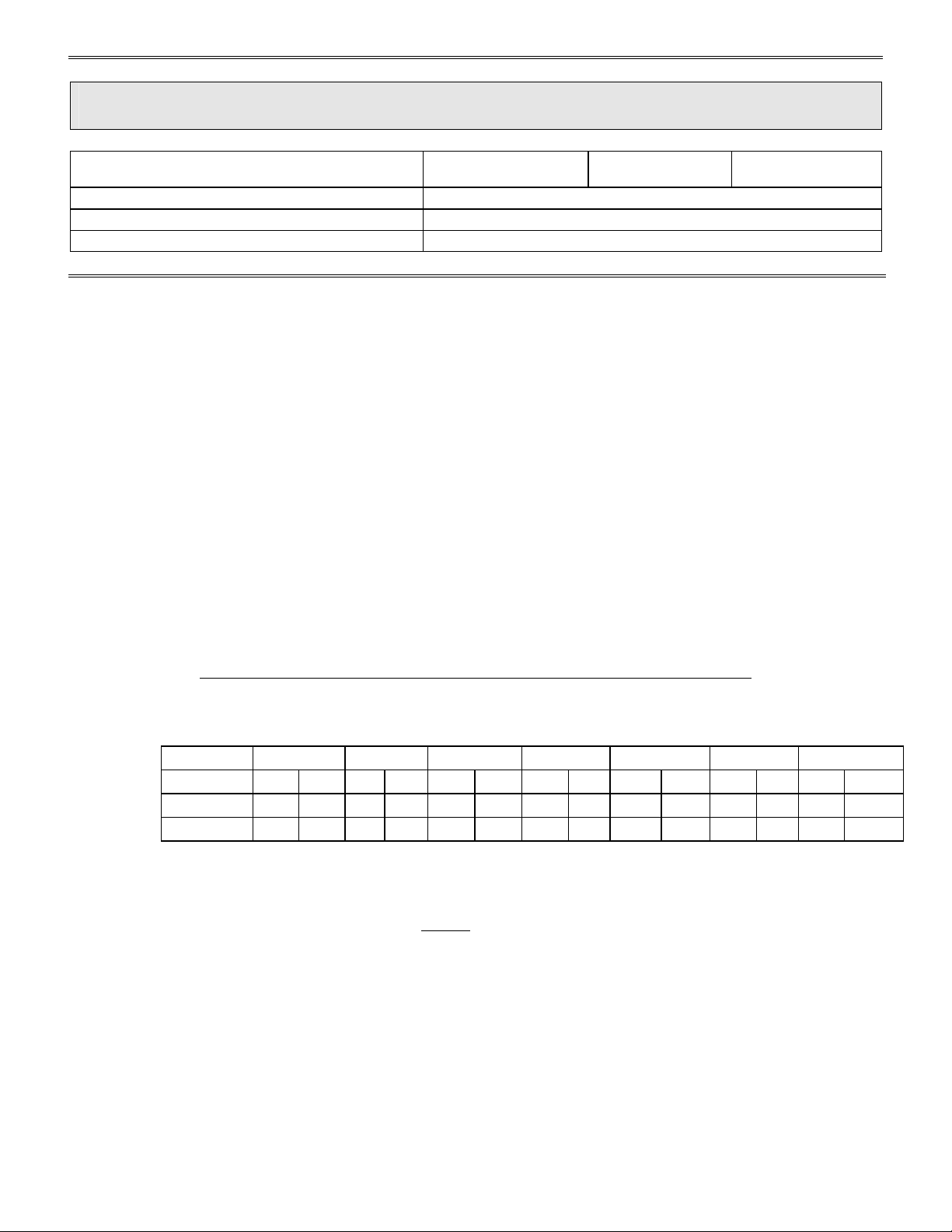
The following chart gives flow rates for Full and Low Flow.
FRAME F200 F300 F400 F500 F600 F650 F800
CONFIG LF FF LF FF LF FF LF FF LF FF LF FF LF FF
LIT/MIN 2.5 11 4 15 7 27 7 27 10 38 10 38 15 60
GPM 0.7 3 1 4 1.9 7 1.9 7 2.6 10 2.6 10 4 15.9
Gland flush water should be 5 to 10 PSI above discharge pressure of pump. If water
is being pumped, then gland flush water may come from the discharge side of the
pump, but this water must be clean
valve should be installed in line to adjust flow. Provide a drain for discharge water
Open suction valve, start pump and let it come up to RPM and pressure.
For a Full or Low Flow Stuffing box seal, tighten the gland follower until a small trickle
of water is coming from around the gland follower. Let pump run for 10 to 15 minutes
DOCUMENT NO:
TED-039
REV. NO: 10 SHEET 15 OF 80
so that no sand, etc., is pumped into Gland area. A
Page 19
TOYO PUMPS NORTH AMERICA CORPORATION
INSTALLATION, OPERATION AND MAINTENANCE MANUAL
TITLE: DBH INSTALLATION OPERATION AND
MAINTENANCE MANUAL
PREPARED BY: KSH RELEASE DATE: MAY 1 1997
APPROVED BY: SN REVISION DATE: MAR 15 2007
SUPERSEDES: REVISED BY:
6.2.2 (ctd)
to be sure packing does not overheat. New packing will wear and seat in, and will
require adjustment from time to time. These seals will leak clear water while running
and may leak slurry when stopped if there is a large suction head present. Gland Flush
water may be left on while pump is not running.
6.2.3 CENTRIFUGAL SEAL
If your pump is equipped with a Centrifugal Seal, grease the seal with 10 or 15 shots of
grease before installing the automatic greaser and starting. The gland follower should
be snugged before starting the pump. Do not over tighten the gland follower or you
will burn the packing and cause damage to the shaft sleeve.
Open suction valve, start pump and let it come up to RPM and pressure.
For a Centrifugal Seal, tighten packing until no leaks occur. Do not over tighten. Let
pump run for 10 to 15 minutes and re-check. A Centrifugal Seal should not leak while
pump is running, but may leak when pump is stopped if there is a large suction head
present.
6.3 START UP
During the first few days of operation while all parts are still new, observe the suction and
discharge gage readings as well as the motor amperage. If a flow meter is available monitor
the pump output as well.
Record these readings in the TECHNICAL DATA SHEET provided in Section 1.0 for future
reference.
These readings should be taken and recorded periodically and will help you to establish an
inspection and maintenance schedule. Keeping track of your pumps performance will make it
easier to identify problems before they become serious and cause undue damage.
DOCUMENT NO:
TED-039
REV. NO: 10
SHEET 16 OF 80
Page 20
TOYO PUMPS NORTH AMERICA CORPORATION
INSTALLATION, OPERATION AND MAINTENANCE MANUAL
TITLE: DBH INSTALLATION OPERATION AND
MAINTENANCE MANUAL
PREPARED BY: KSH RELEASE DATE: MAY 1 1997
APPROVED BY: SN REVISION DATE: MAR 15 2007
SUPERSEDES: REVISED BY:
DOCUMENT NO:
TED-039
REV. NO: 10
SHEET 17 OF 80
7.0 MAINTENANCE
7.1 INSPECTION & ADJUSTMENT FOR WEAR
7.1.1 GENERAL
After your pump has been in service for awhile, the impeller, casing and suction wear
liner will become worn causing the pump to lose efficiency. The speed with which
these parts will wear will depend on the material and concentration being pumped.
As noted in the “Operation Section”, the suction and discharge pressure, as well as the
flow and AMP draw should have been recorded in the “Notes” of the Technical Data
Sheet located in Section 1.0 of this manual.
By comparing the original data with your current readings, the wear and efficiency of
your pump can easily be determined.
The output flow and pressure dropping off with an increase in amperage draw on the
motor signals wear of the wet end components requiring adjustment.
After the pump has been adjusted several times, the wet end parts should be visually
inspected.
Page 21
Page 22
TOYO PUMPS NORTH AMERICA CORPORATION
INSTALLATION, OPERATION AND MAINTENANCE MANUAL
TITLE: DBH INSTALLATION OPERATION AND
MAINTENANCE MANUAL
PREPARED BY: KSH RELEASE DATE: MAY 1 1997
APPROVED BY: SN REVISION DATE: MAR 15 2007
SUPERSEDES: REVISED BY:
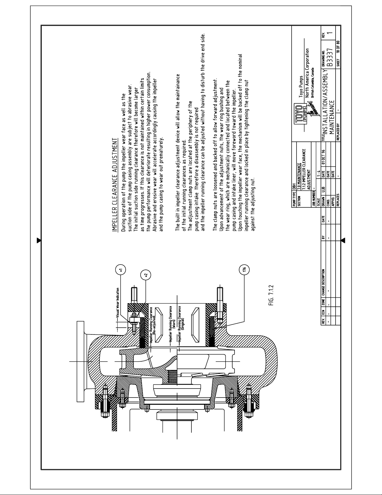
7.1.2 IMPELLER CLEARANCE ADJUSTMENT
Refer to Drawing B3337
BEFORE ADJUSTING FOR WEAR, TAG AND LOCK OUT ALL ELECTRICAL
POWER AND DISCONNECT DRIVE.
ALWAYS FOLLOW PLANT SAFETY PROCEDURES
The pump features a suction side external adjustment feature that allows impeller
running clearance adjustment without the need to re-adjust the pump drive equipment
afterward. Also the mechanical seal, stuffing box or centrifugal seal settings remain
undisturbed and require no re-setting or adjustment.
Loosen the Hex Jam Nuts (Item *1) and back them off toward the casing.
Start to tighten the Hex Nuts (Item *2) against the tabs of the Wear Ring Assembly (Item
176) in a criss-cross fashion until the wear ring bottoms out on the impeller face.
Rotate the shaft by hand to make sure that the wear ring face is up against the impeller
face.
Back the hex nut off 1.5 mm (0.040”) and tighten the hex jam nuts in a criss-cross
fashion until the wear ring tabs butt up against the hex nuts.
Tighten the jam and hex nuts against each other to lock the wear ring assembly in
place.
Rotate the shaft by hand to make sure that the rotating assembly turns freely.
Re-connect your drive gear and install all guards.
FOLLOW PLANT SAFETY PROCEDURES FOR START UP
DOCUMENT NO:
TED-039
REV. NO: 10
SHEET 19 OF 80
Page 23
TOYO PUMPS NORTH AMERICA CORPORATION
INSTALLATION, OPERATION AND MAINTENANCE MANUAL
TITLE: DBH INSTALLATION OPERATION AND
MAINTENANCE MANUAL
PREPARED BY: KSH RELEASE DATE: MAY 1 1997
APPROVED BY: SN REVISION DATE: MAR 15 2007
SUPERSEDES: REVISED BY:
7.1.2.1 VISUAL INSPECTION
Visual inspection is achieved during impeller running clearance adjustment.
The distance between the wear ring tab and the casing provide a visual wear
indicator. Once the wear ring cannot be advanced any further, it is time to
perform a physical inspection of the wet end interior.
The inspection may be performed in two different ways.
1. FRONT PULL OUT
2. BACK PULL OUT
Either method may be used depending on ease of access.
DOCUMENT NO:
TED-039
REV. NO: 10
SHEET 20 OF 80
Page 24

Page 25
TOYO PUMPS NORTH AMERICA CORPORATION
INSTALLATION, OPERATION AND MAINTENANCE MANUAL
TITLE: DBH INSTALLATION OPERATION AND
MAINTENANCE MANUAL
PREPARED BY: KSH RELEASE DATE: MAY 1 1997
APPROVED BY: SN REVISION DATE: MAR 15 2007
SUPERSEDES: REVISED BY:
7.1.3 FRONT PULL OUT
Refer to Drawing B3339
The front pull out method will require the disconnection of the discharge piping and
removal of a portion of the suction pipe to provide enough room for the casing to be
pulled out of the pump.
Before removing any of the connecting fasteners be sure to restrain the pump casing
with a chain or lifting sling adequate to handle the weight.
CAUTION : CASING IS HEAVY, KEEP HANDS CLEAR FROM INSIDE AND
KEEP FEET CLEAR FROM UNDERNEATH
Remove all the Hex Nuts and Washers (Items *3, *4) from the backside of the Bearing
Frame Adapter (Item 332).
There will be four (4) Hex Bolts and Washers (Items *5, *6) that fasten the bearing
frame to the Frame Support Bracket (Item 392).
DO NOT REMOVE THESE BOLTS
Remove the Frame Clamps (Item 333) and the Frame Spacers (Item 334).
The Pump Casing (Item 101) is now ready to be removed.
Make sure that there is enough tension in the lifting chain or sling to keep the casing
from binding on the back liner during removal.
The pump casing interior and the impeller are now exposed for visual inspection.
For a visual inspection of the mechanical seal chamber or centrifugal seal area it is
necessary to remove the Impeller (Item 202).
See Section 7.1.5 IMPELLER REMOVAL
DOCUMENT NO:
TED-039
REV. NO: 10
SHEET 22 OF 80
Page 26
TOYO PUMPS NORTH AMERICA CORPORATION
INSTALLATION, OPERATION AND MAINTENANCE MANUAL
TITLE: DBH INSTALLATION OPERATION AND
MAINTENANCE MANUAL
PREPARED BY: KSH RELEASE DATE: MAY 1 1997
APPROVED BY: SN REVISION DATE: MAR 15 2007
SUPERSEDES: REVISED BY:
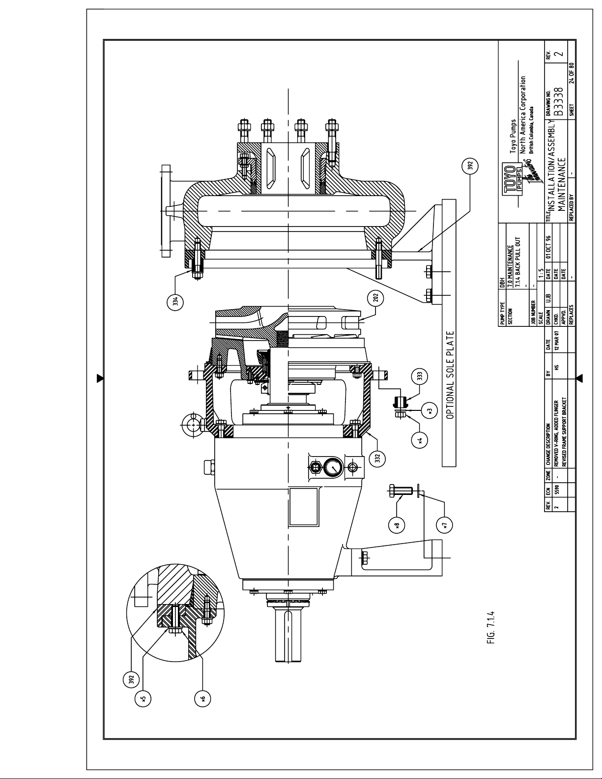
7.1.4 BACK PULL OUT
Refer to Drawing B3338
The back pull out will not require the disconnection of the discharge and suction pipe.
Because the entire bearing frame assembly is removed, it may be necessary to
temporarily support the casing, either directly under the casing or underneath the
suction pipe.
The Frame Support Bracket (Item 392) is designed to support the weight of the pump
casing and any loads and moments generated by the pump itself.
It is not designed as a pipe support; therefore your pipe work should be supported
independent from the pump.
IF YOUR PIPE WORK IS NOT INDEPENDENTLY SUPPORTED YOU MUST PROVIDE ADEQUATE
SUPPORT UNDER THE CASING OR THE SUCTION PIPE.
Before removing any of the connecting fasteners be sure to restrain the bearing frame
assembly with a chain or lifting sling adequate to handle the weight.
CAUTION : BEARING FRAME IS HEAVY, KEEP HANDS CLEAR FROM INSIDE AND
KEEP FEET CLEAR FROM UNDERNEATH
Remove only the Hex Nuts and Washers (Items *3, *4) associated with the Frame
Clamps (Item 333) from the backside of the Bearing Frame Adapter(Item 332).
Remove the four (4) Hex Bolts and Washers (Items *5, *6) that fasten the bearing frame
to the Frame Support Bracket (Item 392).
The Spacer Clamps (Item 334) and associated hex nuts must remain in place since they
will retain the pump casing to the frame support bracket.
DO NOT REMOVE THESE ITEMS
DOCUMENT NO:
TED-039
REV. NO: 10
SHEET 23 OF 80
Page 27
Page 28
TOYO PUMPS NORTH AMERICA CORPORATION
INSTALLATION, OPERATION AND MAINTENANCE MANUAL
TITLE: DBH INSTALLATION OPERATION AND
MAINTENANCE MANUAL
PREPARED BY: KSH RELEASE DATE: MAY 1 1997
APPROVED BY: SN REVISION DATE: MAR 15 2007
SUPERSEDES: REVISED BY:
7.1.4 (ctd)
Remove the bearing housing foot Bolts and Washers (Items *7, *8)
The bearing frame assembly is now ready to be removed. Make sure that there is
enough tension in the lifting chain or sling to keep the back liner from binding on the
casing during removal.
The pump casing interior and the impeller are now exposed for visual inspection.
For a visual inspection of the mechanical seal chamber or centrifugal seal area it is
necessary to remove the Impeller (Item 202).
See Section 7.1.5 IMPELLER REMOVAL
DOCUMENT NO:
TED-039
REV. NO: 10
SHEET 25 OF 80
Page 29
TOYO PUMPS NORTH AMERICA CORPORATION
INSTALLATION, OPERATION AND MAINTENANCE MANUAL
TITLE: DBH INSTALLATION OPERATION AND
MAINTENANCE MANUAL
PREPARED BY: KSH RELEASE DATE: MAY 1 1997
APPROVED BY: SN REVISION DATE: MAR 15 2007
SUPERSEDES: REVISED BY:
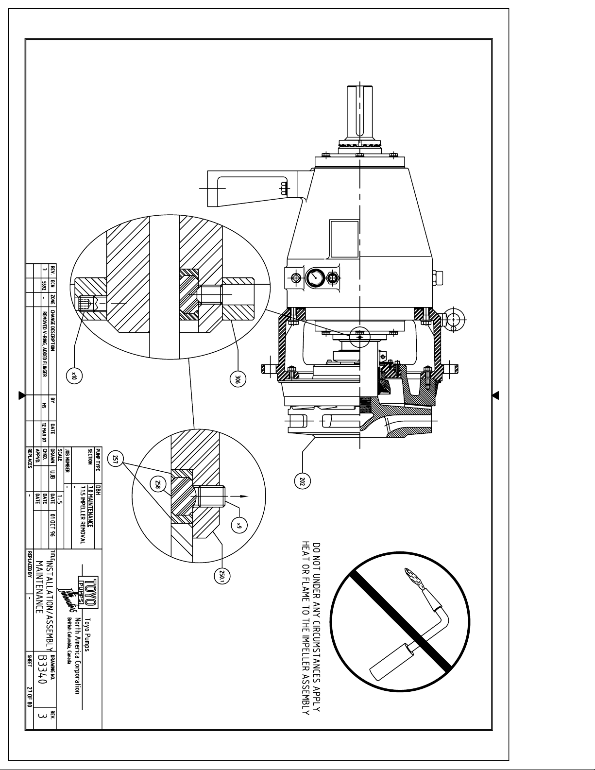
7.1.5 IMPELLER REMOVAL
Refer to Drawing B3340
DO NOT APPLY TORCH FLAME TO IMPELLER ASSEMBLY AT ANY TIME: DOING
SO COULD RESULT IN SERIOUS BODILY HARM
The built in impeller release feature of this pump provides a fast and easy way to
release the thread and shaft tension that is built up during operation.
The Compression Ring (Item 258) and the two Backing Rings (Item 257) are contained
within the Inboard Wear Sleeve (Item 250.1) and are in contact with the face of the
Shaft Sleeve (Item 707).
The compression ring compartment is closed to the outside by a number of Set Screws
(Item *9). These screws prevent the compression ring, which is an elastomer, from
being displaced. The compression ring carries the axial compression load generated
from the input torque and the impeller thread connection. It also serves as a seal to the
bearing housing interior.
To remove the Impeller (Item 202), the Flinger (Item 306) does not have to be removed.
The set screws are accessible through clearance holes in the flinger. Using an Allan
Wrench unscrew the Set Screws (Item *9) about half way out. By doing so the
compression ring is allowed to extrude into the screw holes thereby relieving the shaft
pre-load and thread connection.
Run a chain or lifting sling through the impeller passage and secure it around one of the
impeller vanes. Take up any slack until the chain or sling is tight but not picking up the
frame assembly. Using a sling wrench or made to fit tool rotate the shaft counter
clockwise when viewed from the drive end side. A tap with a hammer on the wrench
handle may be required to break the surface friction between the impeller hub and
shaft sleeve.
DOCUMENT NO:
TED-039
REV. NO: 10
SHEET 26 OF 80
Page 30
Page 31
TOYO PUMPS NORTH AMERICA CORPORATION
INSTALLATION, OPERATION AND MAINTENANCE MANUAL
TITLE: DBH INSTALLATION OPERATION AND
MAINTENANCE MANUAL
PREPARED BY: KSH RELEASE DATE: MAY 1 1997
APPROVED BY: SN REVISION DATE: MAR 15 2007
SUPERSEDES: REVISED BY:
7.1.5 (ctd)
Unscrew the impeller by turning the shaft. Guide the impeller off the end of the shaft so
that the shaft threads will not be damaged.
CAUTION : IMPELLER IS HEAVY, KEEP HANDS CLEAR FROM INSIDE
AND KEEP FEET CLEAR FROM UNDERNEATH
Once the impeller has been removed, screw the set screws back into their original
position flush with the o.d. of the seal sleeve.
7.1.6 MECHANICAL SEAL INSPECTION
Mechanical Seal inspection should be done in accordance with the information
provided for the seal that was sold with your pump.
See Section 10.0 for details
7.1.7 STUFFING BOX INSPECTION
7.1.7.1 LOW FLOW STUFFING BOX
Stuffing box seal inspection is accomplished by disassembly of the cartridge.
The Lantern Ring (Item 706), Throttle Bushing (Item 704) and the Shaft Sleeve
(Item 707) should be inspected and replaced if necessary.
Always replace old packing with OEM packing.
For Packing details see Section 10.0
7.1.7.2 FULL FLOW STUFFING BOX
Stuffing box seal inspection is accomplished by disassembly of the cartridge.
The two Lantern Rings (Items 705, 706) and the Shaft Sleeve (Item 707) should
be inspected and replaced if necessary.
Always replace old packing with OEM packing.
For Packing details see Section 10.0.
DOCUMENT NO:
TED-039
REV. NO: 10
SHEET 28 OF 80
Page 32
TOYO PUMPS NORTH AMERICA CORPORATION
INSTALLATION, OPERATION AND MAINTENANCE MANUAL
TITLE: DBH INSTALLATION OPERATION AND
MAINTENANCE MANUAL
PREPARED BY: KSH RELEASE DATE: MAY 1 1997
APPROVED BY: SN REVISION DATE: MAR 15 2007
SUPERSEDES: REVISED BY:
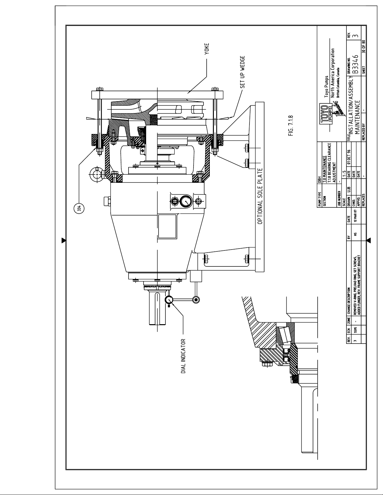
7.1.8 BEARING CLEARANCE ADJUSTMENT
Refer to Drawing B3346
During continuous long term operation, the bearing rollers as well as the bearing races
are subject to mechanical wear causing slight roller-to-race misalignment. This
misalignment can be noticed by an increased level of running noise and vibration. The
pump vibration level should be monitored in conjunction with the overall performance
of your pump as outlined in Section 6.3.
We recommend that you check the bearing end float as a part of your normal
maintenance physical inspection routine. To perform a bearing end float adjustment
you will have to complete either Sections 7.1.3 or 7.1.4. Before any type of adjustment
is made, you should check the existing end float as is.
For bearing frames F800 and larger, it will be necessary to make a yoke or similar
device as depicted in Fig. 7.1.8. Strap the yoke centered across the front of the impeller
and run the two threaded rods thru the holes in the bearing frame. Use the Spacer
Clamps (Item 334) and two hex nuts to secure the yoke in place. For bearing frames
F200, F300, F400, F500, F600, and F650, a pair of large C-clamps can be used.
Place two small set up wedges between the impeller back shroud and tap them in until
the front bearing is hard up against the front race. Make sure that your yoke or Cclamps are not tight.
Next, place a dial indicator on the bearing housing foot and place the point against the
outboard lock nut and zero the dial. Remove the set up wedges and tighten the yoke
nuts or C-clamps evenly across until the rotating assembly bottoms out in the outboard
bearing race. Your indicator reading should give you your total bearing end float.
DOCUMENT NO:
TED-039
REV. NO: 10
SHEET 29 OF 80
Page 33
Page 34
TOYO PUMPS NORTH AMERICA CORPORATION
INSTALLATION, OPERATION AND MAINTENANCE MANUAL
TITLE: DBH INSTALLATION OPERATION AND
MAINTENANCE MANUAL
PREPARED BY: KSH RELEASE DATE: MAY 1 1997
APPROVED BY: SN REVISION DATE: MAR 15 2007
SUPERSEDES: REVISED BY:
7.1.8.1 (ctd)
Compare this value with the proper bearing clearance in Section 8.4.
If the end float exceeds the value in Section 8.4 by more than 0.04 mm (0.0015”) the
bearing end float should be adjusted. Record the bearing end float.
Refer to Section 8.4 and drawing B3301. Remove the end cover screws (item *15), pull
back the end cover and remove the shim pack. The bearing lock nut on the shaft may
have to be removed to remove the end cover.
Remove enough shims from the shim pack to bring the end float back into tolerance
when re-assembled.
Replace the shim pack, end cover and screws. Tighten in criss-cross fashion enough to
properly seat the end cover assembly.
Double check the setting by repeating the previous steps.
DOCUMENT NO:
TED-039
REV. NO: 10
SHEET 31 OF 80
Page 35
TOYO PUMPS NORTH AMERICA CORPORATION
INSTALLATION, OPERATION AND MAINTENANCE MANUAL
TITLE: DBH INSTALLATION OPERATION AND
MAINTENANCE MANUAL
PREPARED BY: KSH RELEASE DATE: MAY 1 1997
APPROVED BY: SN REVISION DATE: MAR 15 2007
SUPERSEDES: REVISED BY:
7.2 LUBRICATION
The pump is fully lubricated prior to shipment.
7.2.1 BEARINGS
The bearings are oil bath lubricated. The oil level can be checked at the sight gage
mounted on the outside of the bearing housing. Oil level should be a minimum of half
way up the gage and a maximum of even with the top of the glass lens.
Do not overfill the bearing housing. Too much oil will cause elevated operating
temperatures and will lower the bearing and oil life.
For a new pump the factory oil fill should be changed after 200 hours.
Oil change intervals greatly depend on operating temperature and the environment in
which the pump operates. Oil temperature should be monitored frequently after start
up of the pump. This can be done simply by reading the Thermometer mounted
beneath the oil sight gage on the bearing housing and recording the value in the
technical data sheet in Section 1.0. The operating temperature for a given bearing
housing type can vary greatly depending on the operating point of the pump (i.e.
speed, TDH and Flow) and the specific gravity of the liquid being pumped. In order to
establish a suitable lubrication schedule and oil type, the pump should be monitored
closely after start up to determine the optimum lubrication type and interval for
continuous operation. With oil-bath lubrication it is generally sufficient to change the
oil every 4000 hours if the temperature is lower than 50° C (120° F). At higher
temperatures or when the oil has the tendency to get contaminated the oil must be
changed more frequently. For temperatures around 100° C (212° F) the oil should be
changed as a minimum every 2000 hours.
Be aware that bearing operating temperatures vary with ambient temperature, and the
viscosity grade of the lubricant may need to be adjusted accordingly.
DOCUMENT NO:
TED-039
REV. NO: 10
SHEET 32 OF 80
Page 36
TOYO PUMPS NORTH AMERICA CORPORATION
INSTALLATION, OPERATION AND MAINTENANCE MANUAL
TITLE: DBH INSTALLATION OPERATION AND
MAINTENANCE MANUAL
PREPARED BY: KSH RELEASE DATE: MAY 1 1997
APPROVED BY: SN REVISION DATE: MAR 15 2007
SUPERSEDES: REVISED BY:
7.2.1 (ctd)
Depending on the bearing operating temperature the following are suitable
lubricating oil viscosity grades.
BEARING OPERATING TEMP.: v ISO: v SAE: v SAE (Gear Oil):
30-70° C (86-158° F) VG 46 20 W 75 W
60-100° C (140-212° F) VG 68 20 W 80 W (Synthetic)
>100° C (>212° F) VG 100 30 W 85 W (Synthetic)
KINEMATIC VISCOSITY
ISO GRADE mm
2
/s @ 40° C @100° C / SUS @ 100° F @ 212° F
VG 46 46 6.5 225 47
VG 68 68 8.5 375 55
VG 100 100 12 550 65
Lubricant brand may be selected based on local availability as long as the required
viscosity is in accordance with the above requirements.
Note: At temperatures exceeding 90° C (194° F), mineral oils will oxidize at a fast
rate. The service life of mineral oils is specified as 30 years at 30° C (86° F). The oil life
is cut in half for every 10° C (18° F) increase in temperature. Therefore at 100°C (212°
F) the service live for mineral oil is approx. 2.8 months or 2025 hours. For elevated oil
temperatures >90° C (194° F) a synthetic oil should always be used.
THE FACTORY OIL FILL IS A PREMIUM GRADE
ALWAYS TAILOR LUBRICATION TYPE AND INTERVALS TO YOUR
APPLICATION SPECIFIC REQUIREMENTS
Please refer to the lubrication guide found in Section 10.0 of this manual for suitable
grease lubricants.
DOCUMENT NO:
TED-039
SYNTHETIC OIL - VG 100
REV. NO: 10 SHEET 33 OF 80
Page 37
TOYO PUMPS NORTH AMERICA CORPORATION
INSTALLATION, OPERATION AND MAINTENANCE MANUAL
TITLE: DBH INSTALLATION OPERATION AND
MAINTENANCE MANUAL
PREPARED BY: KSH RELEASE DATE: MAY 1 1997
APPROVED BY: SN REVISION DATE: MAR 15 2007
SUPERSEDES: REVISED BY:
7.2.2 BEARING HOUSING SEALS
The bearing housing seals are grease lubricated. The grease can be re-charged through
the grease fittings located at the faces of the bearing end covers.
Bearing housing seals should be re-charged every 200 hours.
In order to establish a suitable lubrication schedule, the pump should be monitored
closely after start up to determine the optimum lubrication interval for continuous
operation.
Almost every type of general purpose grease is suitable for lip seal lubrication as long
as temperatures are not too high. If the housing temperature exceeds 80° C (176° F) a
high temperature grease must be used to prevent the oil within the grease from
dissipating too fast.
Lip seals have a limited service life and should be checked every 2000 hours.
If the continuous operating temperature and speed is high, a bearing isolator type seal
should be considered. TOYO offers different types as optional equipment.
Grease seals until grease is coming out from the bore of bearing covers.
Please refer to the lubrication guide found in Section 10.0 of this manual for suitable
grease lubricants.
DOCUMENT NO:
TED-039
REV. NO: 10
SHEET 34 OF 80
Page 38
TOYO PUMPS NORTH AMERICA CORPORATION
INSTALLATION, OPERATION AND MAINTENANCE MANUAL
TITLE: DBH INSTALLATION OPERATION AND
MAINTENANCE MANUAL
PREPARED BY: KSH RELEASE DATE: MAY 1 1997
APPROVED BY: SN REVISION DATE: MAR 15 2007
SUPERSEDES: REVISED BY:
7.3 TROUBLE SHOOTING
• PUMP WILL NOT BUILD PRESSURE
Wet end is worn and needs adjustment; leak in suction side piping
• PUMP WILL NOT HOLD PRIME
Seals in piping or pump are leaking. This is probably on the suction side of the piping, as a
leak in the pressure side would be easily seen
• PUMP WILL NOT PUMP NORMAL VOLUME
Wet end is worn and needs adjustment; leak in suction side piping
NOTE: Loss of flow may be compensated by increasing the operating speed. This is a
short term solution only since the increase in speed will increase the rate of wear.
Adjust the impeller running clearance as soon as possible.
• LEAKING AROUND SHAFT SEAL AREA
MECHANICAL SEAL:
Worn or cracked seal faces, if the seal is equipped with a quench containment check
the quench seal
FULL AND LOW FLOW SEAL:
Tighten gland follower until small trickle of water comes out around gland follower;
replace packing
CENTRIFUGAL SEAL:
Tighten gland follower and grease; replace packing and check alignment
DOCUMENT NO:
TED-039
REV. NO: 10
SHEET 35 OF 80
Page 39
TOYO PUMPS NORTH AMERICA CORPORATION
INSTALLATION, OPERATION AND MAINTENANCE MANUAL
TITLE: DBH INSTALLATION OPERATION AND
MAINTENANCE MANUAL
PREPARED BY: KSH RELEASE DATE: MAY 1 1997
APPROVED BY: SN REVISION DATE: MAR 15 2007
SUPERSEDES: REVISED BY:
DOCUMENT NO:
TED-039
REV. NO: 10
SHEET 36 OF 80
8.0 BEARING FRAME ASSEMBLY
Inspect and inventory all parts before you begin assembly. Clean parts and remove burrs as required.
Bearing frame assembly should be performed in a clean, dust free area. Read these instructions and
drawings before you begin.
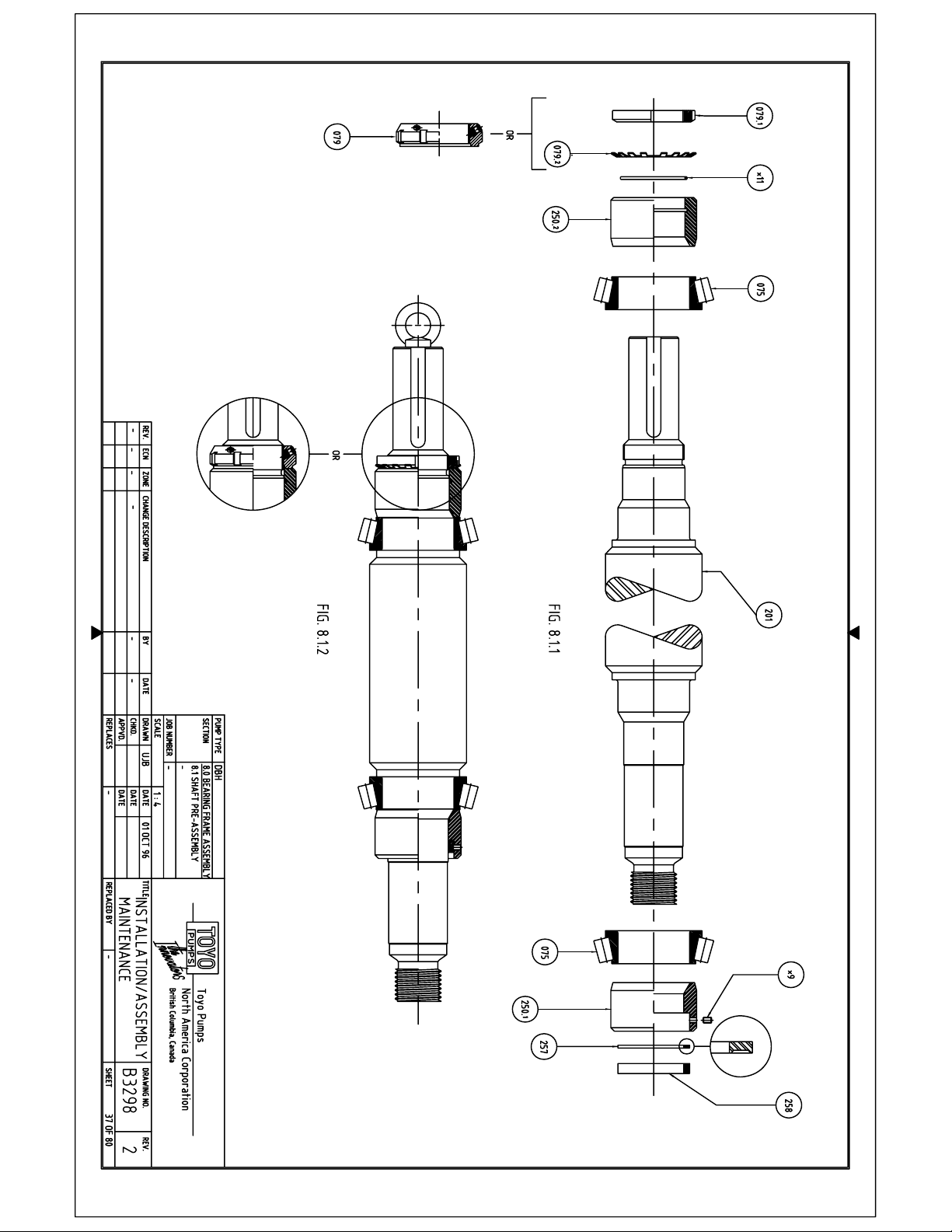
8.1 SHAFT PRE-ASSEMBLY
Refer to Drawing B3298
8.1.1
Position Shaft (Item 201) in a horizontal position on a pair of notched wooden blocks
or similar support.
Preheat the inner Bearing race assemblies (Item 075) to 100° C
(212° F) in a Oven or heated Oil bath.
Caution: Do not heat any Bearing above 150° C (257° F) or permanent changes to the
bearing material may occur. Always wear fireproof insulated gloves when handling
heated components.
Remove one bearing race at a time from oven and slide onto the shaft with the large
shoulder towards the shaft. Hold bearing pressed against shaft shoulder during cooling
for proper seating.
Install O-Ring (Item *11) into the Outboard Seal Sleeve (Item 250.2). Apply a silicone
type lubricant to the O-Ring and inside of the Seal Sleeve.
Slide the Seal Sleeve onto the Shaft from the drive end side and seat it up against the
inner bearing race.
Position the Bearing Lock Washer (Item 079.2) on the shaft and Install Bearing Lock
Nut (Item 079.1)
Note: On some Frame Types a “KMT” Type Bearing Lock Nut (Item 079) is used which
has integral set screws and does not require a Lock Washer. Tighten set screws to
minimum 25 Nm, maximum 35 Nm.
NEVER USE AN OPEN FLAME TO HEAT BEARINGS
Page 40
Page 41

TOYO PUMPS NORTH AMERICA CORPORATION
INSTALLATION, OPERATION AND MAINTENANCE MANUAL
TITLE: DBH INSTALLATION OPERATION AND
MAINTENANCE MANUAL
PREPARED BY: KSH RELEASE DATE: MAY 1 1997
APPROVED BY: SN REVISION DATE: MAR 15 2007
SUPERSEDES: REVISED BY:
8.1.1 (ctd)
Apply a silicone type lubricant to the inside of the Inboard Seal Sleeve (Item 250.1).
Slide the Seal Sleeve onto the Shaft from the Wet End side (threaded end) and seat it up
against the inner bearing race.
Insert one of the Backing Rings (Item 257) into the Seal Sleeve cavity with the recessed
face toward the threaded end of the Shaft.
Apply a silicone type lubricant to the Compression Ring (Item 258) and insert it into the
Seal Sleeve cavity.
Note: Use a dull, soft object (Brass drift) to push Backing Ring and Compression
Ring against the cavity shoulder. Do not scratch or burr the shaft and cavity
surfaces.
Insert the Set Screws (Item *9) into the Seal Sleeve and tighten until the top of the Set
Screw is flush with the o.d. of the Seal Sleeve. This will squeeze the Compression
Ring and hold the Seal Sleeve in place for further assembly.
8.1.2
Insert a Lifting Eye Bolt into the drive end of the shaft for further assembly. The
Bearings must be wrapped and sealed with a suitable material such as plastic foil or oil
paper to be protected from dust and dirt for intermediate storage between assembly
steps.
DOCUMENT NO:
TED-039
REV. NO: 10
SHEET 38 OF 80
Page 42
TOYO PUMPS NORTH AMERICA CORPORATION
INSTALLATION, OPERATION AND MAINTENANCE MANUAL
TITLE: DBH INSTALLATION OPERATION AND
MAINTENANCE MANUAL
PREPARED BY: KSH RELEASE DATE: MAY 1 1997
APPROVED BY: SN REVISION DATE: MAR 15 2007
SUPERSEDES: REVISED BY:
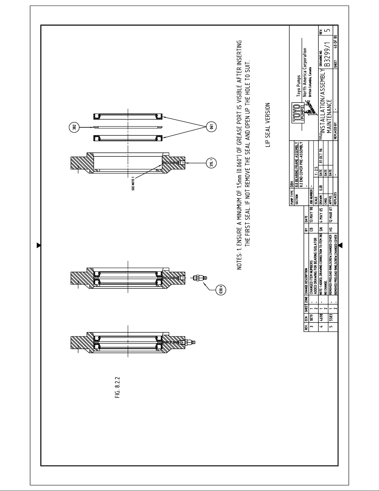
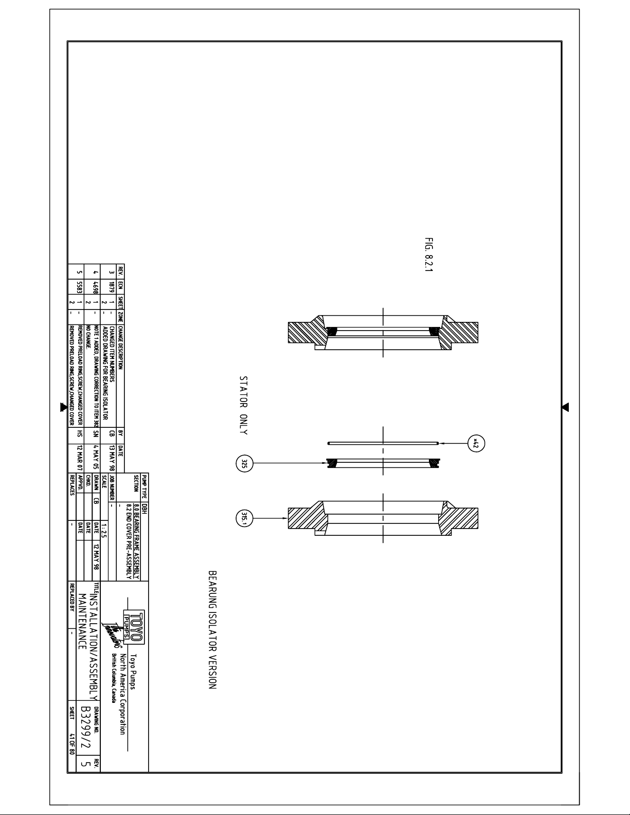
8.2 BEARING END COVER PRE-ASSEMBLY
Refer to Drawing B3299/1 for Lip Seal Assembly (Fig. 8.2.1)
Refer to Drawing B3299/2 for Bearing Isolator Assembly (Fig. 8.2.2)
8.2.1 Lip Seal Version
Position Inboard and Outboard Bearing End Covers (Item 315.1) with the lip seal socket
up on a flat working surface.
Apply a thin film of a silicone type lubricant to the periphery of the Lip Seals (Item
061). Position the first seal, with the sealing lip down, into the lead-in chamfer and
push it into the socket using a proper installation tool.
Place the Grease Ring (Item 382) grooved side down on top of the first lip seal.
Position the second seal with the sealing lip up into the lead-in chamfer and push into
socket using a proper installation tool.
Install the Grease Fitting (Item 030.4). Pack Grease into the area between the two
sealing lips and charge the grease nipple.
DOCUMENT NO:
TED-039
REV. NO: 10
SHEET 39 OF 80
Page 43
Page 44
Page 45
TOYO PUMPS NORTH AMERICA CORPORATION
INSTALLATION, OPERATION AND MAINTENANCE MANUAL
TITLE: DBH INSTALLATION OPERATION AND
MAINTENANCE MANUAL
PREPARED BY: KSH RELEASE DATE: MAY 1 1997
APPROVED BY: SN REVISION DATE: MAR 15 2007
SUPERSEDES: REVISED BY:
8.2.2 Bearing Isolator Version
Position Inboard and Outboard Bearing End Covers (Item 315.1) with the stator socket
up on a flat working surface.
Install the O-Ring (Item *42) into the o-ring groove on the outside diameter of the Stator
(Item 325).
Apply a silicone type lubricant to the o-ring and pilot diameter of the Stator. Position
the Stator into the lead-in chamfer and press it into the socket. Make sure that the O-
Ring is not damaged and the flange face of the stator is flush with the face of the End
Cover.
DOCUMENT NO:
TED-039
REV. NO: 10
SHEET 42 OF 80
Page 46
TOYO PUMPS NORTH AMERICA CORPORATION
INSTALLATION, OPERATION AND MAINTENANCE MANUAL
TITLE: DBH INSTALLATION OPERATION AND
MAINTENANCE MANUAL
PREPARED BY: KSH RELEASE DATE: MAY 1 1997
APPROVED BY: SN REVISION DATE: MAR 15 2007
SUPERSEDES: REVISED BY:
Page intentionally Blank
DOCUMENT NO:
TED-039
REV. NO: 10
SHEET 43 OF 80
Page 47
Page 48
Page 49
TOYO PUMPS NORTH AMERICA CORPORATION
INSTALLATION, OPERATION AND MAINTENANCE MANUAL
TITLE: DBH INSTALLATION OPERATION AND
MAINTENANCE MANUAL
PREPARED BY: KSH RELEASE DATE: MAY 1 1997
APPROVED BY: SN REVISION DATE: MAR 15 2007
SUPERSEDES: REVISED BY:
8.3 BEARING HOUSING ASSEMBLY
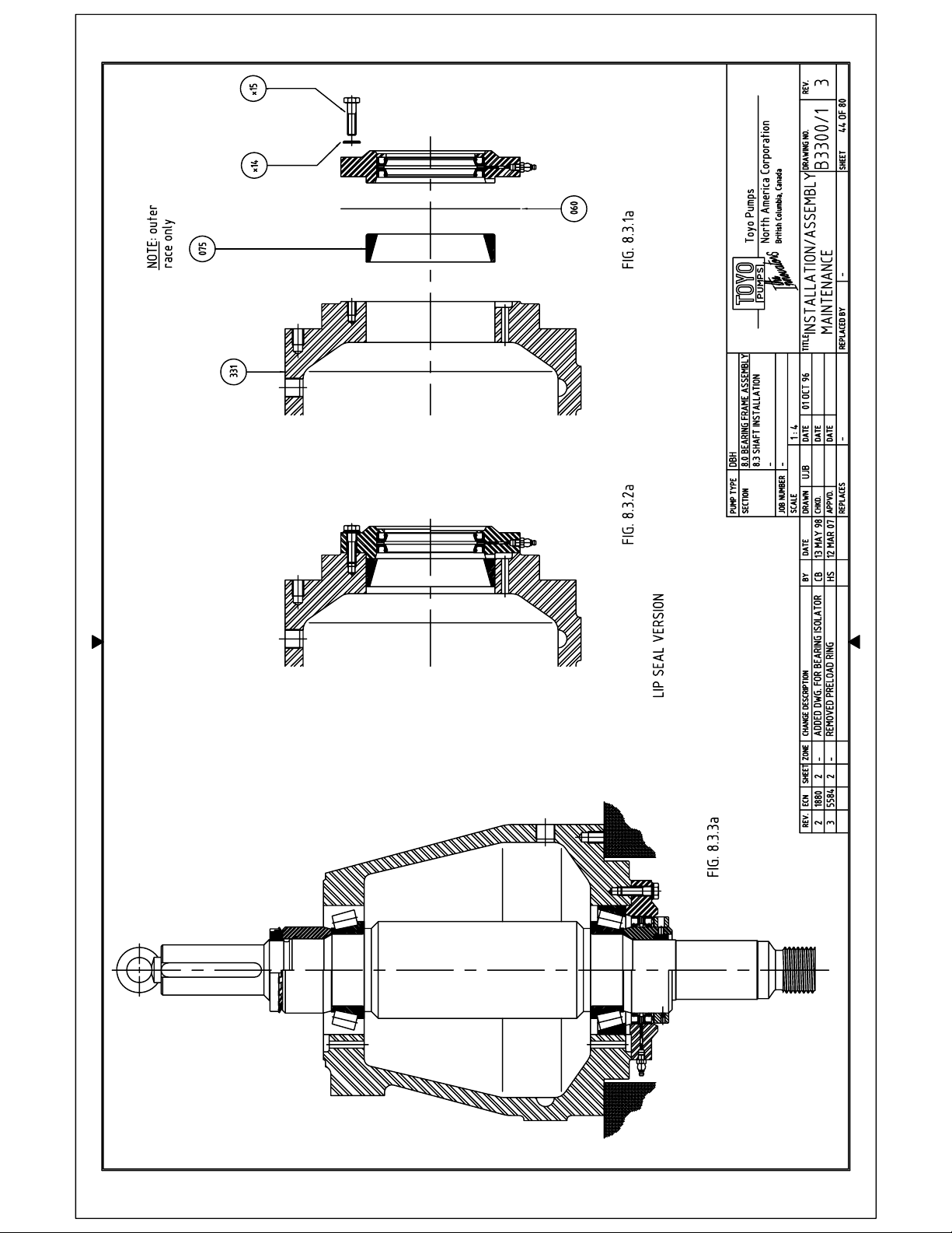
Refer to Drawing B3300/1 for Lip Seal Assembly (Fig. 8.3.1a, 8.3.2a, 8.3.3a)
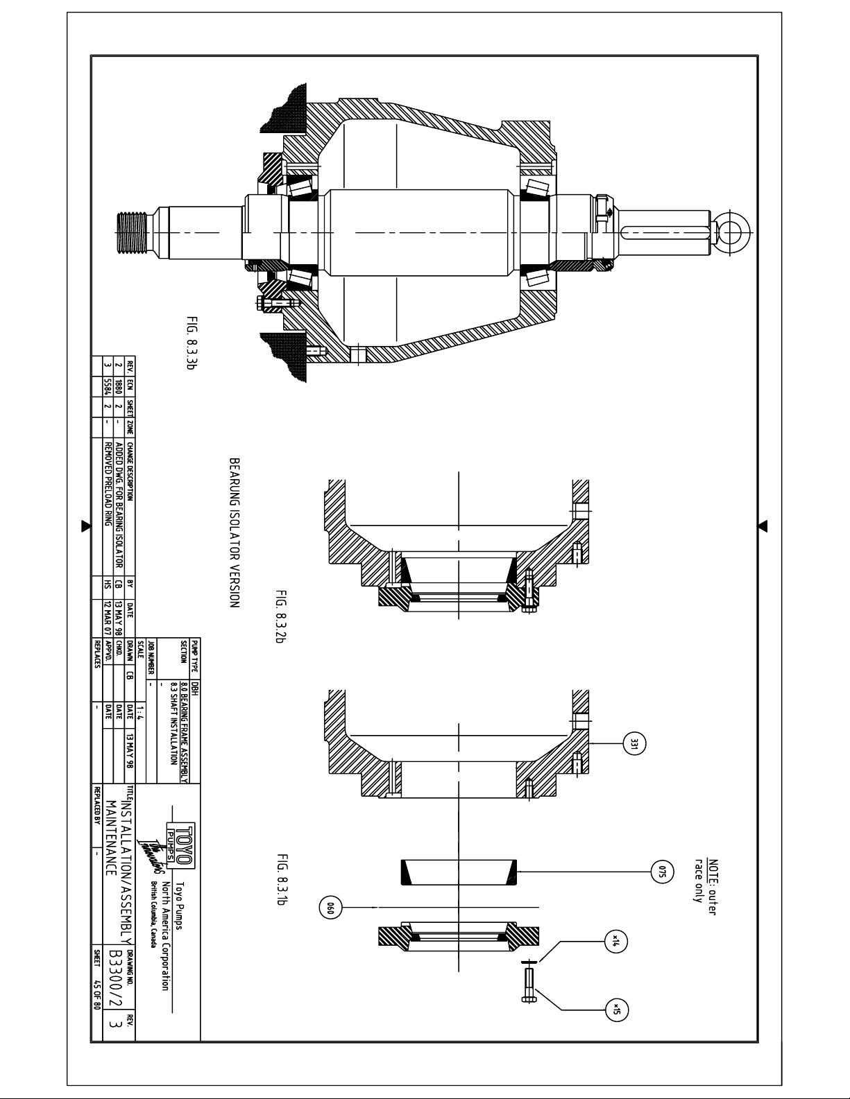
Refer to Drawing B3300/2 for Bearing Isolator Assembly (Fig. 8.3.1b, 8.3.2b, 8.3.3b)
8.3.1
Position Bearing Housing (Item 331) horizontally on a working surface sturdy enough
to support the weight. Apply a thin film of oil to the inside of the inboard bearing bore.
Insert the outer bearing race, large diameter first, into the bore until the race is located
6 mm (1/4”) inside the housing. Place the End Cover Gasket (Item 060) onto the pre-
assembled Inboard Bearing Cover. Line up the oil return slot and push the cover into
the housing bore.
8.3.2
Insert the End Cover bolts and Washers (Items *14, *15) and tighten in a criss-cross
fashion to required torque value.
Note: For required torque values refer to the torque table in Section 10.0.
8.3.3
Position Bearing Housing in a vertical position with the inboard side down on a
suitable stable support. Pick up the shaft pre-assembly by the lifting eye bolt and
position over the outboard bearing bore. Lower the shaft into the housing slowly,
taking care not to damage the lower oil seals, until the bearing rollers are seated against
the lower outer bearing race. Remove Lifting device and tap the end of the shaft with a
soft hammer to ensure proper seating of the shaft assembly.
Note: Bearing Housing weights are given in Section 10.0.
DOCUMENT NO:
TED-039
REV. NO: 10
SHEET 46 OF 80
Page 50
TOYO PUMPS NORTH AMERICA CORPORATION
INSTALLATION, OPERATION AND MAINTENANCE MANUAL
TITLE: DBH INSTALLATION OPERATION AND
MAINTENANCE MANUAL
PREPARED BY: KSH RELEASE DATE: MAY 1 1997
APPROVED BY: SN REVISION DATE: MAR 15 2007
SUPERSEDES: REVISED BY:
8.4 BEARING CLEARANCE SETTING
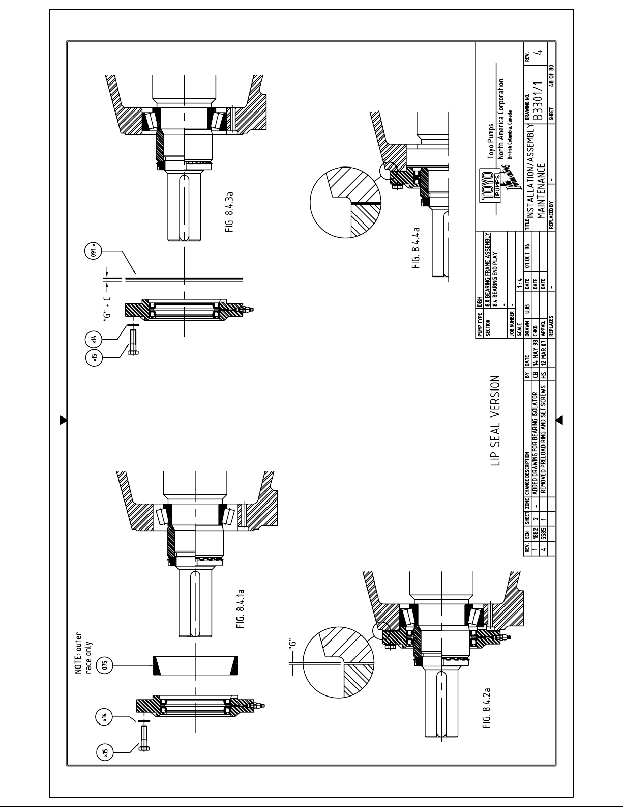
Refer to Drawing B3301/1 for Lip Seal Assembly (Fig. 8.4.1a, 8.4.2a, 8.4.3a, 8.4.4a)
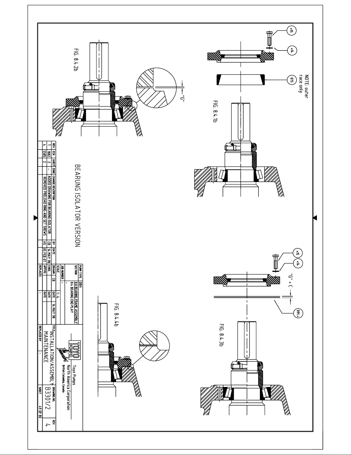
Refer to Drawing B3301/2 for Bearing Isolator Assembly (Fig. 8.4.1b, 8.4.2b, 8.4.3b, 8.4.4b)
8.4.1
Apply a thin film of oil to the outside of the outer bearing race.
Insert the outer bearing race, large diameter first, into the bore until the race is seated
against the outboard bearing rollers.
Line up the oil return slots with the housing and insert the pre-assembled outboard end
cover (Section 8.2) into the bearing housing until seated against the bearing race.
Insert the End Cover Bolts and Washers (Items *14, *15) and tighten in criss-cross
fashion enough to properly seat the end cover assembly.
Do not over tighten at this point or damage to the bearings can result
Tighten the bolts until the shaft can just be turned by hand.
8.4.2
With a feeler gage, establish clearance, “G”, between the housing and end cover faces.
Check this in four positions around the circumference to be sure that the end cover is
seated square with the bearing outer race.
DOCUMENT NO:
TED-039
REV. NO: 10
SHEET 47 OF 80
Page 51
Page 52
Page 53
TOYO PUMPS NORTH AMERICA CORPORATION
INSTALLATION, OPERATION AND MAINTENANCE MANUAL
TITLE: DBH INSTALLATION OPERATION AND
MAINTENANCE MANUAL
PREPARED BY: KSH RELEASE DATE: MAY 1 1997
APPROVED BY: SN REVISION DATE: MAR 15 2007
SUPERSEDES: REVISED BY:
8.4.3
Once this clearance is established make a note of it and remove the end cover
assembly.
Assemble a Shim Pack or peel solid laminated shim stock (Item 091.*) having a
thickness equal to the measured gap (“G”) plus the recommended bearing clearance (C)
from Bearing End Play table.
Bearing End Play
FRAME 200 - C=0.10mm – 0.15mm (0.004”-0.006”)
FRAME 300 - C=0.10mm – 0.15mm (0.004”-0.006”)
FRAME 400 - C=0.18mm – 0.23mm (0.007”-0.009”)
FRAME 500 - C=0.18mm – 0.23mm (0.007”-0.009”)
FRAME 600 - C=0.25mm – 0.30mm (0.010”-0.012”)
FRAME 650 - C=0.25mm – 0.30mm (0.010”-0.012”)
FRAME 800 - C=0.36mm – 0.41mm (0.014”-0.016”)
To determine which Frame number applies to your pump refer to the Technical
Data Sheet in Section 1.0.
Place the final Shim Pack (Item 091.*) onto the pre-assembled Outboard Bearing
Cover. Line up the oil return and pin slots and push the cover into the housing
bore until seated against the Bearing Housing face.
Insert the End Cover Bolts and Washers (Items *14, *15) and tighten in crisscross fashion to proper torque value.
Note: For required torque values refer to the torque table in Section 10.0.
Once all bolts have been tightened, check the assembly for free and smooth
rotation by turning the shaft by hand.
DOCUMENT NO:
TED-039
REV. NO: 10
SHEET 50 OF 80
Page 54
TOYO PUMPS NORTH AMERICA CORPORATION
INSTALLATION, OPERATION AND MAINTENANCE MANUAL
TITLE: DBH INSTALLATION OPERATION AND
MAINTENANCE MANUAL
PREPARED BY: KSH RELEASE DATE: MAY 1 1997
APPROVED BY: SN REVISION DATE: MAR 15 2007
SUPERSEDES: REVISED BY:
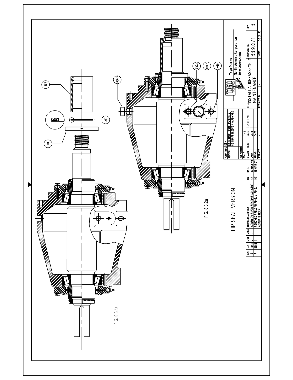
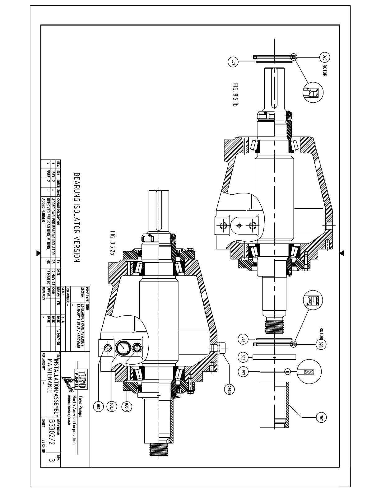
8.5 SHAFT SLEEVE, FLINGER AND HARDWARE
Refer to Drawing B3302/1 for Lip Seal Assembly (Fig. 8.5.1a, 8.5.2a)
Refer to Drawing B3302/2 for Bearing Isolator Assembly (Fig. 8.5.1b, 8.5.2b)
8.5.1
Position the bearing housing horizontally, resting on the flat pad up front of the housing
and the bearing housing foot pad on the drive end side.
*For figure 8.5.1b only. Install the O-Ring (Item *43) into the o-ring groove on the
inside diameter of the Rotor (Item 325). Apply a silicone type lubricant to the o-ring
and inside diameter of the Rotor. Slide the Rotor over the inboard and outboard seal
sleeves with the grooved face toward the Stator until it is flush with the Stator. Make
sure that the o-ring is not damaged during the installation process.
Install the flinger (Item 306) on the inboard seal sleeves and locate it against the shaft
shoulder with the clearance holes adjacent to the seal sleeve set screws. Tighten the
flinger set screws.
Insert the second Backing Rings (Item 257) into the Seal Sleeve cavity with the recessed
face toward the bearing housing.
DOCUMENT NO:
TED-039
REV. NO: 10
SHEET 51 OF 80
Page 55
Page 56
Page 57
TOYO PUMPS NORTH AMERICA CORPORATION
INSTALLATION, OPERATION AND MAINTENANCE MANUAL
TITLE: DBH INSTALLATION OPERATION AND
MAINTENANCE MANUAL
PREPARED BY: KSH RELEASE DATE: MAY 1 1997
APPROVED BY: SN REVISION DATE: MAR 15 2007
SUPERSEDES: REVISED BY:
Note: Use a dull, soft object (Brass drift) to push Backing Ring against
Compression Ring. Do not scratch or burr the shaft and cavity surfaces.
Apply a light coat of an anti galling paste (NeverSeize or similar) to the front portion of
the shaft.
Slide the Shaft Sleeve (Item 707) onto the shaft and seat it into the seal sleeve cavity
against the backing ring.
8.5.2
To prevent dust and dirt particles from entering the bearing housing, all the remaining
hardware must be installed now.
Breather Vent (Item 030.3), Oil Sight Glass (Item 030.2), Oil Temp.
Thermometer (Item 030.1) and Oil Drain Plug (Item 080) have NPT Thread
connections.
Apply Teflon tape or a paste type sealant to the threads prior to installation.
DOCUMENT NO:
TED-039
REV. NO: 10
SHEET 54 OF 80
Page 58
TOYO PUMPS NORTH AMERICA CORPORATION
INSTALLATION, OPERATION AND MAINTENANCE MANUAL
TITLE: DBH INSTALLATION OPERATION AND
MAINTENANCE MANUAL
PREPARED BY: KSH RELEASE DATE: MAY 1 1997
APPROVED BY: SN REVISION DATE: MAR 15 2007
SUPERSEDES: REVISED BY:
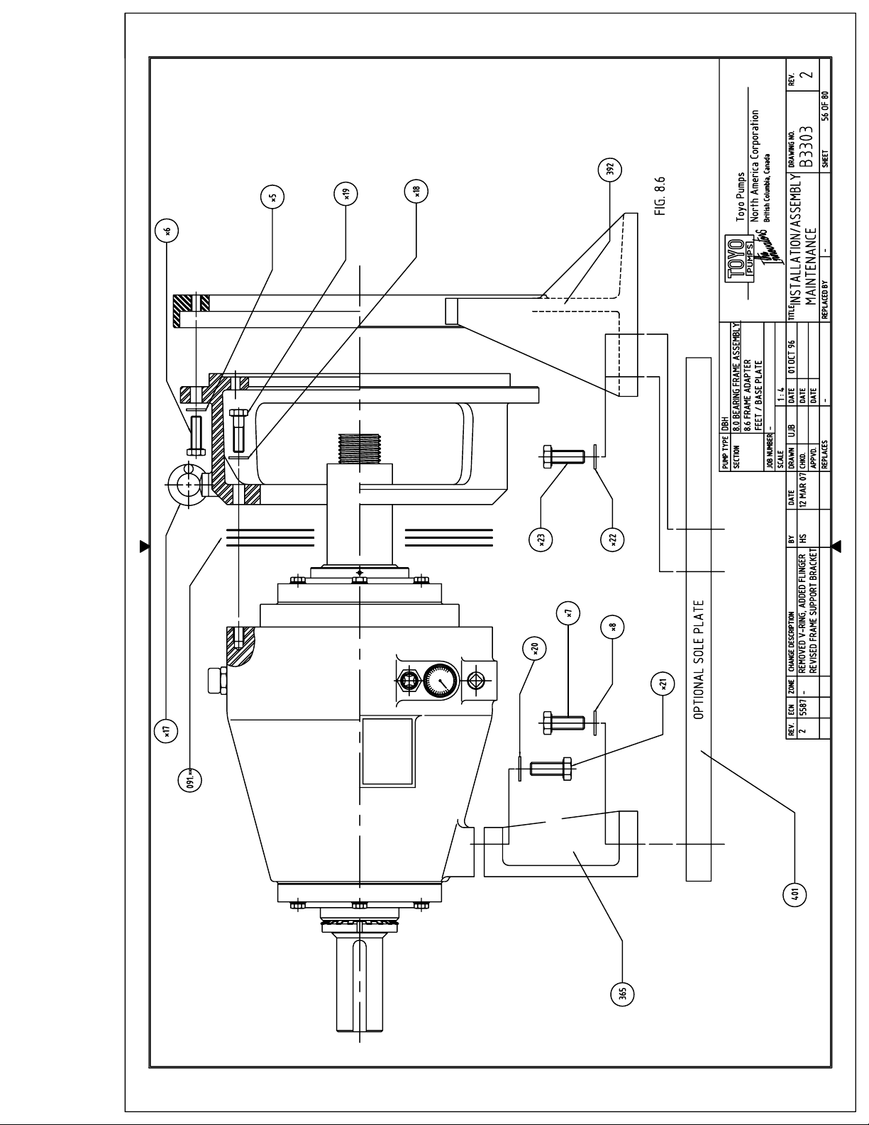
8.6 FRAME ADAPTER, FEET AND BASE PLATE
Refer to Drawing B3303
8.6.1
Insert the Lifting Eye Bolt (Item *17) into the Frame Adapter (Item 332)
Slide the Frame Adapter onto its seat and insert the Bolts and Washers (Items *18, *19)
into the bearing housing.
Tighten the bolts until a 5 mm (3/16”) gap remains between the bearing housing and
frame adapter faces.
Insert the Spacer Pack (Item 091.**) into the gap and tighten the bolts to the required
torque.
Note: The Spacer Pack consists of 3 each half shims for top and bottom.
For Bolt Torque table see Section 10.0.
Slide the Frame Support Bracket (Item 392) onto its seat and insert the Bolts and
Washers (Items *5, *6) from the frame adapter side and tighten to required torque.
Pick up the assembly by the lifting eye
Position the Bearing Housing Foot (Item 365) underneath, insert the Bolts and Washers
(Items *20, *21) and hand tighten.
Lower the assembly onto the optional Sole Plate (Item 401) and insert Bolts and
Washers (Items *22, *23) and tighten to required torque.
Note : Pumps supplied with direct drive, overhead, reverse overhead, and side by side
motor mounts will not have a sole plate.
Tighten the Bearing Housing Foot Bolts (Item *7, *21) to required torque.
DOCUMENT NO:
TED-039
REV. NO: 10
SHEET 55 OF 80
Page 59
Page 60
Page 61

TOYO PUMPS NORTH AMERICA CORPORATION
INSTALLATION, OPERATION AND MAINTENANCE MANUAL
TITLE: DBH INSTALLATION OPERATION AND
MAINTENANCE MANUAL
PREPARED BY: KSH RELEASE DATE: MAY 1 1997
APPROVED BY: SN REVISION DATE: MAR 15 2007
SUPERSEDES: REVISED BY:
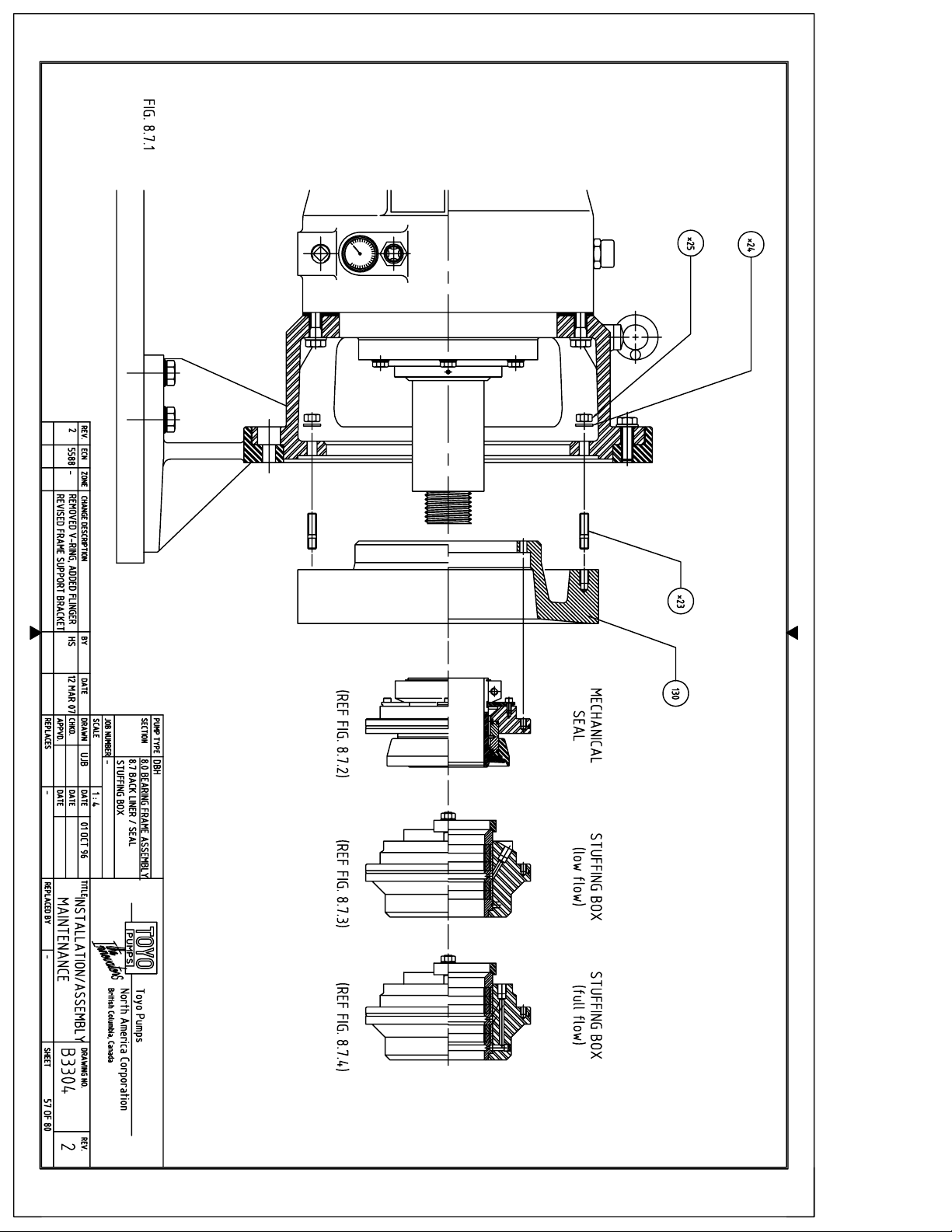
8.7 BEARING SIDE LINER, MECHANICAL SEAL, STUFFING BOX
8.7.1 BEARING SIDE LINER
Refer to Drawing B3304
Insert the Studs (Item *23) into the Bearing Side Liner (Item 130) and tighten until they
bottom out.
Stand up the Bearing Side Liner and cradle it with a nylon lifting sling wide enough to
cover the width of the liner less 10 mm (3/8”). Line up the studs with the bolt hole
pattern in the bearing frame adapter, so that two of the six seal cartridge mounting
holes are on the vertical centreline.
DO NOT USE METAL CHAIN SINCE IT WILL SLIP OFF THE LINER
Hoist the liner into position and guide the o.d. into the spigot on the frame adapter.
CAUTION : LINER IS HEAVY, KEEP HANDS CLEAR FROM INSIDE AND
KEEP FEET CLEAR FROM UNDERNEATH
Once liner is seated into spigot install Washers and Hex Nuts (Items *24, *25) from
backside and tighten.
DO NOT REMOVE SLING UNTIL THE LINER IS SECURED
Remove the lifting sling and tighten the Hex Nuts to required torque.
Note: For Bolt torque values see Section 10.0.
For Mechanical Seal installation continue with 8.7.2
For Low Flow Stuffing Box installation continue with 8.7.3
For Full Flow Stuffing Box installation continue with 8.7.4
DOCUMENT NO:
TED-039
REV. NO: 10
SHEET 58 OF 80
Page 62

TOYO PUMPS NORTH AMERICA CORPORATION
INSTALLATION, OPERATION AND MAINTENANCE MANUAL
TITLE: DBH INSTALLATION OPERATION AND
MAINTENANCE MANUAL
PREPARED BY: KSH RELEASE DATE: MAY 1 1997
APPROVED BY: SN REVISION DATE: MAR 15 2007
SUPERSEDES: REVISED BY:
8.7.2 MECHANICAL SEAL
Toyo offers different makes of heavy duty slurry mechanical seals based on the
customers preference and/or application requirements. These seals are all
interchangeable with one another as well as with the stuffing box type shaft seals,
therefore not requiring any type of modification to your pump or the bearing side liner
in which they are mounted.
The installation of the mechanical seal cartridge to the bearing side liner covered here
is typical for all makes.
There are differences in the way the seal cartridges are fastened to the shaft however,
depending on make and model.
REFER TO THE SPECIFIC DOCUMENTATION FOR THE SEAL SOLD WITH YOUR PUMP
INSTALLATION:
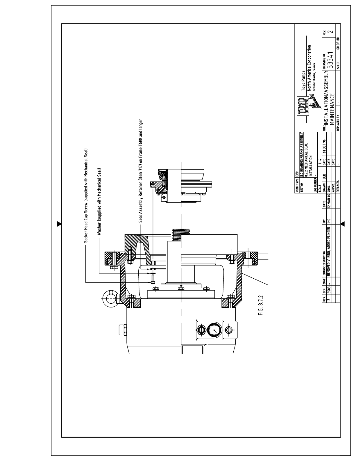
Refer to Drawing B3341
Double check the Bearing Side Liner bore and Shaft Sleeve for any nicks and burrs and
remove if necessary.
Apply a light coat of a Silicone type lubricant (usually supplied with the seal) to the
liner bore, shaft sleeve o.d. as well as the O-Rings located in the bore and
circumference of the seal cartridge.
Align the mounting holes in the cartridge flange with the through holes of the liner.
Slide the cartridge assembly onto the shaft sleeve and push it toward the liner. This will
stop once the o-ring reaches the end of the shaft sleeve. Apply even pressure across the
face of the cartridge sleeve to push the o-ring over the sleeve. Push the assembly back
into the liner socket.
DO NOT USE A HAMMER OR FORCE THE ASSEMBLY
Install the Socket Head Cap Screws and Washers supplied with the seal from the
backside of the liner and tighten to recommended torque.
DOCUMENT NO:
TED-039
REV. NO: 10
SHEET 59 OF 80
Page 63
Page 64
TOYO PUMPS NORTH AMERICA CORPORATION
INSTALLATION, OPERATION AND MAINTENANCE MANUAL
TITLE: DBH INSTALLATION OPERATION AND
MAINTENANCE MANUAL
PREPARED BY: KSH RELEASE DATE: MAY 1 1997
APPROVED BY: SN REVISION DATE: MAR 15 2007
SUPERSEDES: REVISED BY:
8.7.2 (ctd)
On bearing frames F600 and larger A seal assembly retainer (Item 717) is fitted in
between the bearing side liner and mechanical seal fasteners.
The cartridge assembly is now secured to the liner and the remaining step of securing
the mechanical seal sleeve to the shaft sleeve will have to be completed AFTER the
Impeller has been installed.
Cartridge type mechanical seals will have so called “setting plates” or “centering taps”
installed when received. The purpose of these parts is to hold the rotating and
stationary portions of the cartridge assembly centered to each other for easy installation
and to compress the spring element of the seal to the proper pre-load at the same time.
DO NOT REMOVE THESE PARTS PRIOR TO COMPLETING IMPELLER
INSTALLATION AND SECURING SEAL SLEEVE TO SHAFT SLEEVE
REFER TO THE SPECIFIC DOCUMENTATION FOR THE SEAL SOLD WITH
YOUR PUMP
If you have completed the installation thus far refer to :
SECTION 9.0 WET END ASSEMBLY
9.1 IMPELLER / SEAL RUBBER
9.1.1 IMPELLER INSTALLATION
8.7.2.1 FINAL SEAL ASSEMBLY
Having completed step 9.1.1 you are now ready to secure the seal sleeve to the
shaft sleeve. Depending on seal type, size and make there will be a number of
set screws, a split clamp collar or on larger sizes a shrink disc assembly on the
back end (inboard side) of the seal sleeve.
Tighten as per the included instructions specific to your seal.
Remove all “setting plates“ or “centering tabs” and store for later use.
These parts will be required if the removal of the seal cartridge becomes
necessary for maintenance purposes.
DOCUMENT NO:
TED-039
REV. NO: 10
SHEET 61 OF 80
Page 65
TOYO PUMPS NORTH AMERICA CORPORATION
INSTALLATION, OPERATION AND MAINTENANCE MANUAL
TITLE: DBH INSTALLATION OPERATION AND
MAINTENANCE MANUAL
PREPARED BY: KSH RELEASE DATE: MAY 1 1997
APPROVED BY: SN REVISION DATE: MAR 15 2007
SUPERSEDES: REVISED BY:
8.7.3 STUFFING BOX (LOW FLOW)
Toyo offers two different types of stuffing box shaft seals based on the customers
preference and/or application requirements.
These seals are interchangeable with each other as well as a choice of heavy duty
mechanical seals, therefore not requiring any type of modification to your pump or the
bearing side liner in which they are mounted.
The stuffing box assemblies are identical to one another with the exception of the low
flow type having a throttle bushing and the full flush arrangement having a secondary
lantern ring in the bottom of the box.
The stuffing box body is drilled with both low flow and full flush connections and
utilizes the same packing, packing gland, primary lantern ring, gland follower and
fasteners.
Changing from low flow to full flush requires only the exchange of the bottom lantern
ring with the throttle bushing and moving the water inlet port plug from one location to
the other.
PRE-ASSEMBLY:
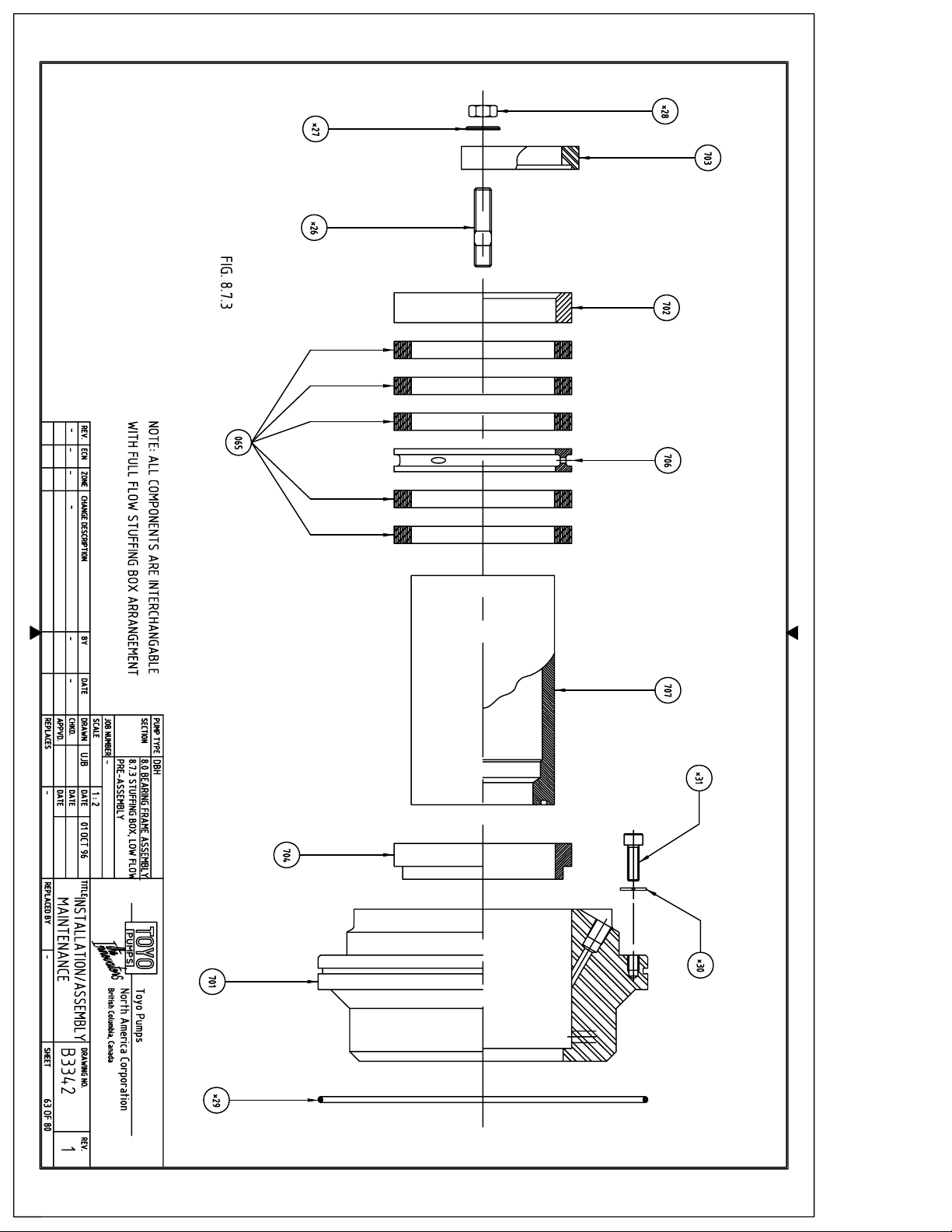
Refer to Drawing B3342
For ease of assembly pre-pack the box by utilizing the Shaft Sleeve (Item 707)
Double check the Shaft Sleeve for any nicks and burrs and remove if necessary.
Place the Stuffing Box (Item 701) large bore up on a flat working surface. Apply a light
coat of oil to the bore surface to aid in parts insertion.
Insert the Throttle Bushing (Item 704) into the bore and slide it into its socket in the
bottom of the box.
Insert the Shaft Sleeve (Item 707) into the Throttle Bushing bore.
DOCUMENT NO:
TED-039
REV. NO: 10
SHEET 62 OF 80
Page 66
Page 67
TOYO PUMPS NORTH AMERICA CORPORATION
INSTALLATION, OPERATION AND MAINTENANCE MANUAL
TITLE: DBH INSTALLATION OPERATION AND
MAINTENANCE MANUAL
PREPARED BY: KSH RELEASE DATE: MAY 1 1997
APPROVED BY: SN REVISION DATE: MAR 15 2007
SUPERSEDES: REVISED BY:
8.7.3 (ctd)
Place the first ring of Packing (Item 065) around the shaft sleeve and push it into the
bore half of its width. Use the Packing Gland (Item 702) to square it up and push it into
the bore until slightly recessed with the box face.
Place the second Ring of Packing around the shaft sleeve. Locate the cut 180° offset
from the cut in the first ring and push it into the bore. Use the Packing Gland to square
it up and push it into the bore until slightly recessed with the box face.
Slide the Lantern Ring (Item 706) over the shaft sleeve and start it into the bore. Use the
Packing Gland to square it up and push it into the bore until slightly recessed with the
box face.
Continue to insert the last three Packing Rings in the same fashion as the first two,
making sure that the cuts are staggered 180° offset from each other.
Insert the Studs (Item *26) into the Stuffing Box body.
Slide the Packing Gland (Item 702) over the shaft sleeve and into the bore as far as
possible.
Position the Gland Follower (Item 703) on top of the packing gland and install the Hex
Nuts and Washers (Items *27, *28) and tighten until the shaft sleeve can no longer be
rotated by hand.
Insert the O-Ring (Item *29) into the stuffing box flange.
Socket head cap screws and washers (Items *30, *31) are mounting screws and will be
used later.
This finishes the pre-assembly. For flush water connection see Section 8.7.5
DOCUMENT NO:
TED-039
REV. NO: 10
SHEET 64 OF 80
Page 68
TOYO PUMPS NORTH AMERICA CORPORATION
INSTALLATION, OPERATION AND MAINTENANCE MANUAL
TITLE: DBH INSTALLATION OPERATION AND
MAINTENANCE MANUAL
PREPARED BY: KSH RELEASE DATE: MAY 1 1997
APPROVED BY: SN REVISION DATE: MAR 15 2007
SUPERSEDES: REVISED BY:
8.7.4 STUFFING BOX (FULL FLOW)
Toyo offers two different types of stuffing box shaft seals based on the customers
preference and/or application requirements.
These seals are interchangeable with one another as well as a choice of heavy duty
mechanical seals, therefore not requiring any type of modification to your pump or the
bearing side liner in which they are mounted.
The low flow and full flow stuffing box assemblies are identical to each other with the
exception of the low flow type having a throttle bushing and the full flush arrangement
having a secondary lantern ring in the bottom of the box.
The stuffing box body is drilled with both low flow and full flush connections and
utilizes the same packing, packing gland, primary lantern ring, gland follower and
fasteners.
Changing from low flow to full flush requires only the exchange of the bottom lantern
ring with the throttle bushing and moving the water inlet port plug from one location to
the other.
PRE-ASSEMBLY:
Refer to Drawing B3343
For ease of assembly pre-pack the box by utilizing the Shaft Sleeve (Item 707)
Double check the Shaft Sleeve for any nicks and burrs and remove if necessary.
Place the Stuffing Box (Item 701) large bore up on a flat working surface. Apply a light
coat of oil to the bore surface to aid in parts insertion.
Insert the Full Flush Lantern Ring (Item 706.1) into the bore and slide it into its socket in
the bottom of the box.
Insert the Shaft Sleeve (Item 707) into the Throttle Bushing bore.
DOCUMENT NO:
TED-039
REV. NO: 10
SHEET 65 OF 80
Page 69
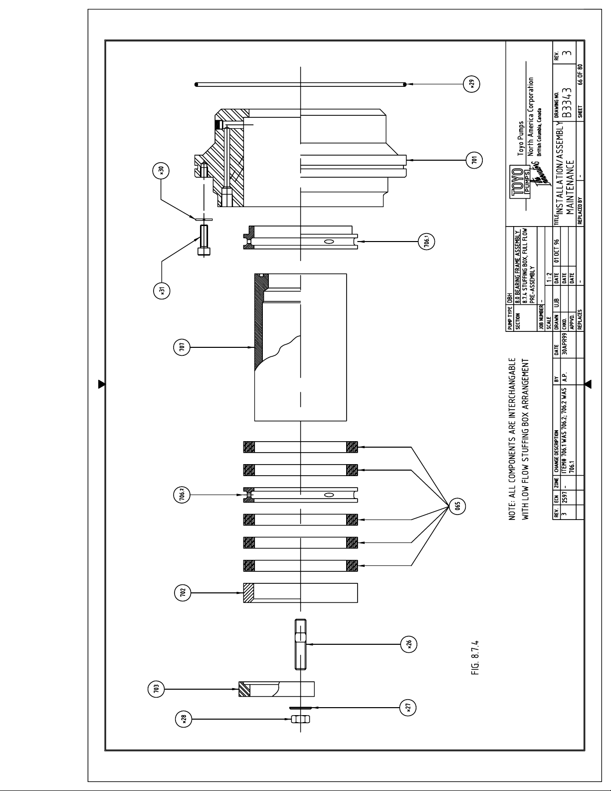
Page 70
TOYO PUMPS NORTH AMERICA CORPORATION
INSTALLATION, OPERATION AND MAINTENANCE MANUAL
TITLE: DBH INSTALLATION OPERATION AND
MAINTENANCE MANUAL
PREPARED BY: KSH RELEASE DATE: MAY 1 1997
APPROVED BY: SN REVISION DATE: MAR 15 2007
SUPERSEDES: REVISED BY:
8.7.4 (ctd)
Place the first ring of Packing (Item 065) around the shaft sleeve and push it into the
bore half of its width. Use the Packing Gland (Item 702) to square it up and push it into
the bore until slightly recessed with the box face.
Place the second Ring of Packing around the shaft sleeve. Locate the cut 180° offset
from the cut in the first ring and push it into the bore. Use the Packing Gland to square
it up and push it into the bore until slightly recessed with the box face.
Slide the Lantern Ring (Item 706.2) over the shaft sleeve and start it into the bore. Use
the Packing Gland to square it up and push it into the bore until slightly recessed with
the box face.
Continue to insert the last three Packing Rings in the same fashion as the first two,
making sure that the cuts are staggered 180° offset from each other.
Insert the Studs (Item *26) into the Stuffing Box body.
Slide the Packing Gland (Item 702) over the shaft sleeve and into the bore as far as
possible.
Position the Gland Follower (Item 703) on top of the packing gland and install the Hex
Nuts and Washers (Items *27, *28) and tighten until the shaft sleeve can no longer be
rotated by hand.
Insert the O-Ring (Item *29) into the stuffing box flange.
Socket head cap screws and washers (Items *30, *31) are mounting screws and will be
used later.
This finishes the pre-assembly. For flush water connection see Section 8.7.6
DOCUMENT NO:
TED-039
REV. NO: 10
SHEET 67 OF 80
Page 71
TOYO PUMPS NORTH AMERICA CORPORATION
INSTALLATION, OPERATION AND MAINTENANCE MANUAL
TITLE: DBH INSTALLATION OPERATION AND
MAINTENANCE MANUAL
PREPARED BY: KSH RELEASE DATE: MAY 1 1997
APPROVED BY: SN REVISION DATE: MAR 15 2007
SUPERSEDES: REVISED BY:
8.7.5 LOW FLOW WATER INLET
Refer to Drawing B3344
For a Low Flow configuration, the full flow water inlet must be plugged.
Apply Teflon tape or a paste type sealant to the threads of the Pipe Plug (Item *32)
before installing into the port connection.
The Full Flow port connection to be plugged is located on the FLAT PORTION of the
gland follower side stuffing box face.
8.7.6 FULL FLOW WATER INLET
For a Full Flow configuration, the low flow water inlet must be plugged.
Apply Teflon tape or a paste type sealant to the threads of the Pipe Plug (Item *32)
before installing into the port connection.
The Low Flow port connection to be plugged is located on the INCLINED FACE
PORTION of the gland follower side stuffing box face.
DOCUMENT NO:
TED-039
REV. NO: 10
SHEET 68 OF 80
Page 72
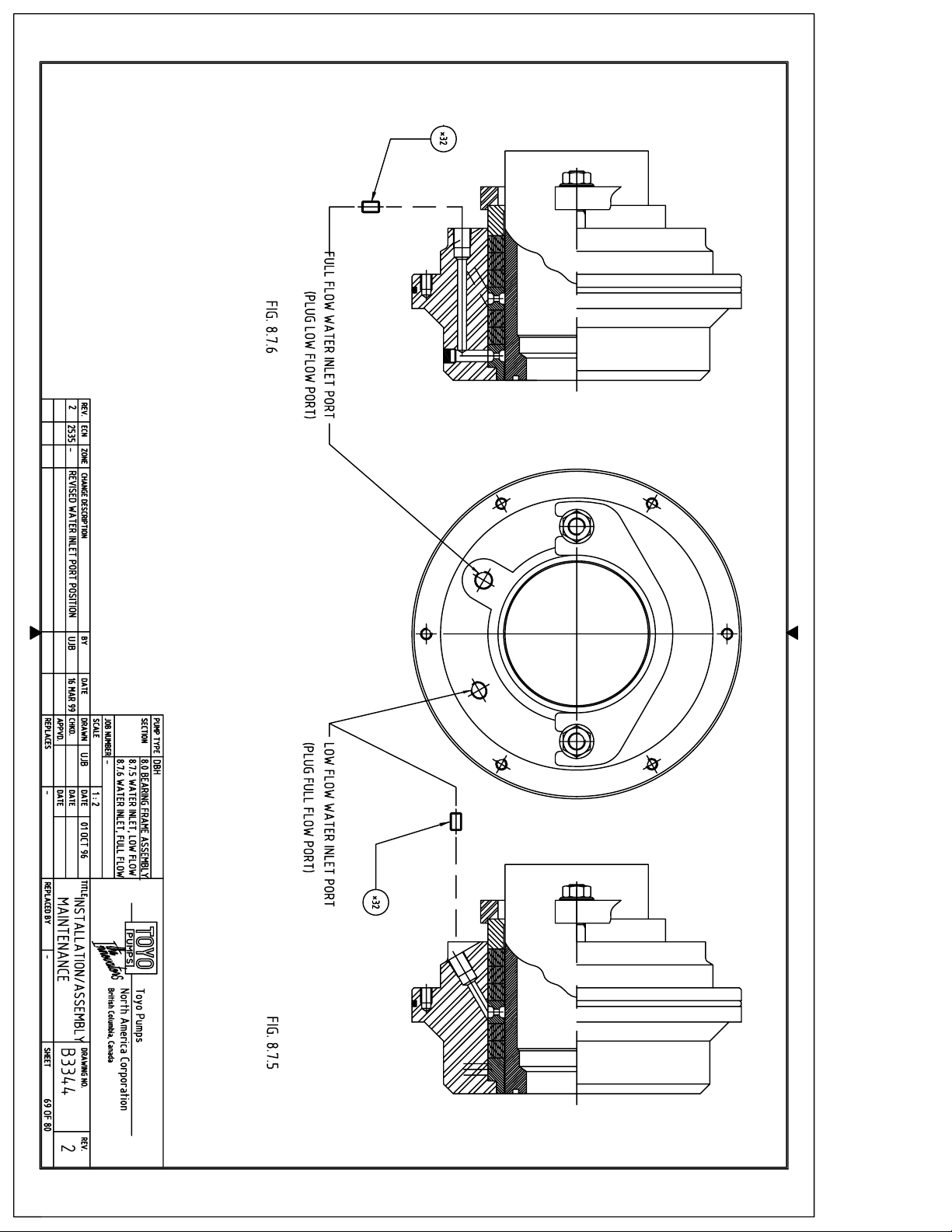
Page 73
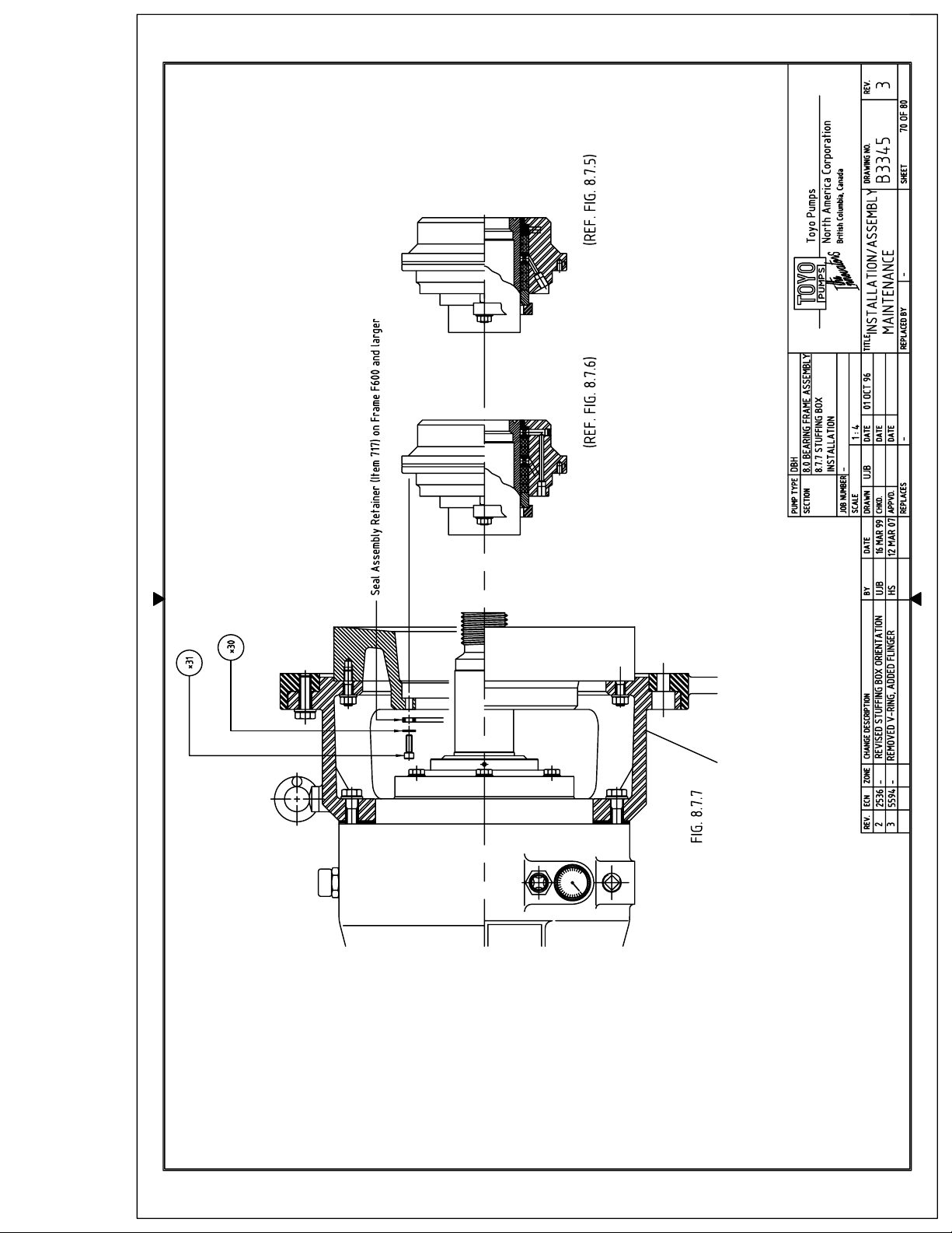
Page 74
TOYO PUMPS NORTH AMERICA CORPORATION
INSTALLATION, OPERATION AND MAINTENANCE MANUAL
TITLE: DBH INSTALLATION OPERATION AND
MAINTENANCE MANUAL
PREPARED BY: KSH RELEASE DATE: MAY 1 1997
APPROVED BY: SN REVISION DATE: MAR 15 2007
SUPERSEDES: REVISED BY:
8.7.7 STUFFING BOX INSTALLATION
Refer to Drawing B3345
The installation of the Low Flow and Full Flow Stuffing Box cartridge to the bearing
side liner covered here is standard for both types.
Double check the Bearing Side Liner bore and Shaft for any nicks and burrs and
remove if necessary. Install Push-out screws into Liner pockets (Frame 600 and larger –
Refer to Wet End Assembly Drawing)
Apply a light coat of a Silicone type lubricant to the liner bore as well as the O-Ring
located at the circumference of the box flange.
Apply a light coat of an anti-galling paste (Never Seize or similar) to the front portion of
the shaft.
Align the mounting holes in the box flange with the through holes of the liner.
Slide the box assembly onto the shaft and push it toward the liner.
The cartridge will stop once the shaft sleeve reaches the bottom of the seal sleeve.
Apply even pressure across the face of the box to push the o-ring into the liner socket.
DO NOT USE A HAMMER OR FORCE THE ASSEMBLY
Install the Socket Head Cap Screws and Washers (Item *30, *31) supplied with the
stuffing box from the backside of the liner and tighten to recommended torque.
On bearing frames F600 and larger A seal assembly retainer (Item 717) is fitted in
between the bearing side liner and mechanical seal fasteners.
Note: For Bolt torque values see Section 10.0
This finishes the Bearing Frame assembly.
For Wet End installation refer to section 9.0
DOCUMENT NO:
TED-039
REV. NO: 10
SHEET 71 OF 80
Page 75

TOYO PUMPS NORTH AMERICA CORPORATION
INSTALLATION, OPERATION AND MAINTENANCE MANUAL
TITLE: DBH INSTALLATION OPERATION AND
MAINTENANCE MANUAL
PREPARED BY: KSH RELEASE DATE: MAY 1 1997
APPROVED BY: SN REVISION DATE: MAR 15 2007
SUPERSEDES: REVISED BY:
DOCUMENT NO:
TED-039
REV. NO: 10
SHEET 72 OF 80
9.0 WET END ASSEMBLY
Inspect and inventory all parts before you begin assembly. Clean parts and remove burrs as required.
Read these instructions and drawings before you begin.
9.1 IMPELLER INSTALLATION
Refer to Drawing B3305
Inspect the shaft end thread prior to impeller installation. Make sure that the lead in is free of
any burrs and metal peelings.
Inspect the shaft sleeve face and the o-ring groove and wipe clean.
Apply a light coat of a silicone type paste lubricant to the shaft sleeve face and o-ring groove.
Place the shaft sleeve O-Ring (Item *32) into the groove. Apply additional lubricant paste if
needed to hold the o-ring in place until the impeller is installed.
Wipe the o.d of the bearing side liner clean and dry. Stretch the casing Seal Rubber (Item 173)
over the liner and position it up against the socket face in the bearing frame adapter. If
properly installed, the seal rubber lip will protrude approx. 1 - 2 mm (0.040-0.080”) past the
face of the Frame Support Bracket (Item 392). Make sure the casing seal is seated evenly all
around its circumference.
Apply a liberal amount of an anti-galling agent such as “Never Seize” to the shaft thread.
Run a chain or lifting sling through the Impeller (Item 202) and secure it around one of the
impeller vanes.
Page 76
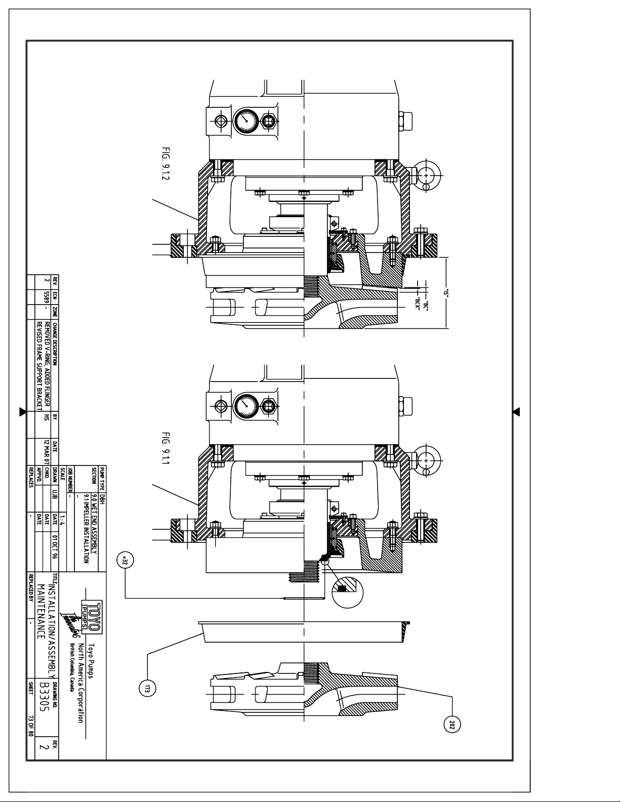
Page 77
TOYO PUMPS NORTH AMERICA CORPORATION
INSTALLATION, OPERATION AND MAINTENANCE MANUAL
TITLE: DBH INSTALLATION OPERATION AND
MAINTENANCE MANUAL
PREPARED BY: KSH RELEASE DATE: MAY 1 1997
APPROVED BY: SN REVISION DATE: MAR 15 2007
SUPERSEDES: REVISED BY:
9.1 (ctd)
Hoist the Impeller up front of the shaft thread and center it up. Using a sling wrench or made
to fit tool start turning the shaft in a clock wise manner while at the same time guiding the
impeller onto the thread. This should be done by two people working together.
CAUTION : IMPELLER IS HEAVY, KEEP HANDS CLEAR FROM INSIDE AND KEEP
FEET CLEAR FROM UNDERNEATH
Once the thread catches, continue to turn the shaft until the impeller hub face is
approximately 3 mm (1/8”) from the face of the shaft sleeve.
Double check that the shaft sleeve o-ring is still seated in the groove.
Run the impeller home with a solid pull on your shaft wrench.
Use a heavy hammer and hit the tool handle to tighten up the impeller connection as much as
possible.
At this point it is necessary to check the impeller running clearance “BC” or “BCX” on the
bearing liner side as well as the position of the impeller wear face (intake side) “IS” in relation
to the frame support bracket face.
The dimension “BC” refers to impellers without expellers and dimension “BCX” refers to
expeller type impellers. Refer to the table below for nominal values.
FRAME DIM “BC” mm / in. DIM “BCX” mm / in.
200
300 7.5 mm / .295” 1.5 mm / .059”
400 10.5 mm / .413” 2.5 mm / .098”
500 10.5 mm / .413” 2.5 mm / .098”
600 10.5 mm / .413” 2.5 mm / .098”
650
800
DOCUMENT NO:
TED-039
REV. NO: 10
SHEET 74 OF 80
Page 78
TOYO PUMPS NORTH AMERICA CORPORATION
INSTALLATION, OPERATION AND MAINTENANCE MANUAL
TITLE: DBH INSTALLATION OPERATION AND
MAINTENANCE MANUAL
PREPARED BY: KSH RELEASE DATE: MAY 1 1997
APPROVED BY: SN REVISION DATE: MAR 15 2007
SUPERSEDES: REVISED BY:
9.1 (ctd)
Dimensions “BC” or “BCX” should be within +0.0 /- 1.0 mm (0.040”).
Using a feeler gage measure the actual clearance and make a note of it.
Lay a straight edge across the impeller face and measure the distance “IS” from the impeller
face to the frame adapter face top and bottom and make a note of it. Rotate the straight edge
90° and repeat. The impeller should be square within 0.4 mm (0.015”).
At this point we can measure the depth of the pump casing from the face on the bearing side
liner bore side to the machined face on the inside front of the casing.
This dimension should be a minimum of 1 mm (0.040”) larger than dimension “IS” previously
measured at the impeller.
If all settings are correct, continue to section 9.2
If the casing depth is smaller than the impeller setting “IS” proceed as follows.
Loosen the bearing housing foot hold down bolts (Item *7). Loosen the bearing frame adapter
bolts (Item *19) and back off approx. 3 mm (1/8”), see Dwg. B3303.
Retract the bearing frame until the impeller bottoms out against the bearing side liner. Insert
additional shims (Item 091.**) top and bottom until there is minimal clearance left between
the bearing housing shoulder and the frame adapter. Tighten the bolts to the required torque
and rotate the shaft to make sure the impeller does not bind on the liner face.
Remeasure the distance “IS” and compare to the casing depth to verify proper clearance once
assembled.
Retighten the bearing housing foot bolts to the required torque.
DOCUMENT NO:
TED-039
REV. NO: 10
SHEET 75 OF 80
Page 79
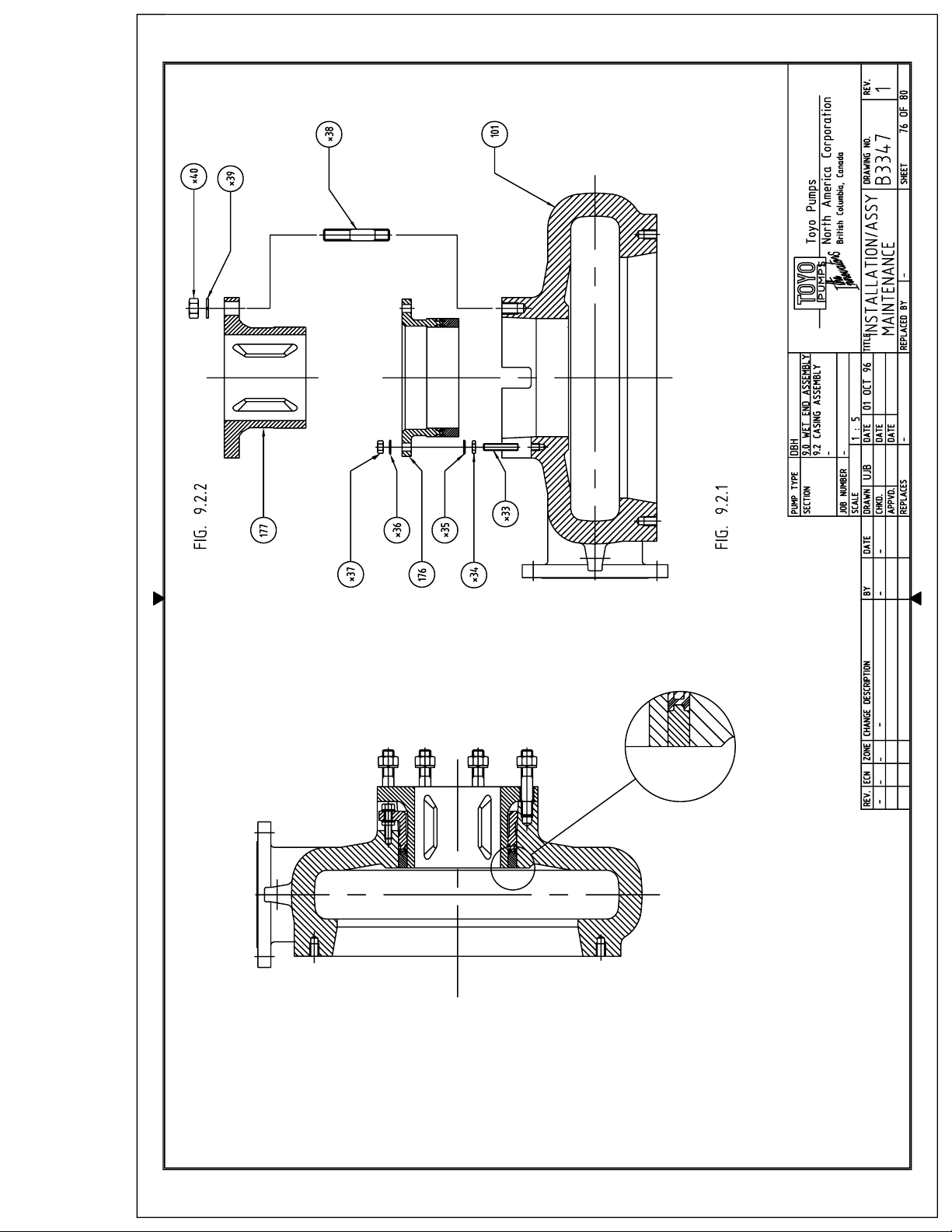
Page 80
TOYO PUMPS NORTH AMERICA CORPORATION
INSTALLATION, OPERATION AND MAINTENANCE MANUAL
TITLE: DBH INSTALLATION OPERATION AND
MAINTENANCE MANUAL
PREPARED BY: KSH RELEASE DATE: MAY 1 1997
APPROVED BY: SN REVISION DATE: MAR 15 2007
SUPERSEDES: REVISED BY:
9.2 CASING ASSEMBLY
Refer to Drawing B3347
9.2.1 WEAR RING INSTALLATION
Place the Casing (Item 101) with the suction side up on a suitable working surface.
Wipe the inside of the machined bore clean, inspect it for any nicks and burrs and
remove if required.
Insert the wear ring Studs (Item *33) into the casing. Place the Washers and Hex Jam
Nuts (Items *34, *35) onto the studs in this order and screw the nuts up against the
casing.
Double check to make sure that the bore is clean and apply a light coat of a silicone
paste type lubricant to the machined bore surface and the outside of the Wear Ring
Assembly (Item 176).
Line up the tabs with the slots in the casing and insert the wear ring portion into the
casing bore. The assembly will stop once the elastomer seal portion reaches the casing
bore. Lay a crow bar or similar tool across the face of the wear ring tabs into the slots
of the casing and push the wear ring assembly into the bore until the studs protrude
thru the holes far enough to place the Washer and Hex Nut (Items *36, *37) onto the
studs. Tighten the hex nuts in a criss - cross fashion until the front wear ring face is
flush with the inside of the casing wear face. Tighten the backside jam nuts against the
front to lock the wear ring assembly into position.
Note: On some larger intake sizes, the wear ring studs protrude past the
front face of the casing. If this is the case proceed as follows:
Insert the wear ring Studs (Item *33) into the casing. Place the Washers and Hex Jam
Nuts (Items *34, *35) onto the studs in this order and screw the nuts up against the
casing.
DOCUMENT NO:
TED-039
REV. NO: 10
SHEET 77 OF 80
Page 81
TOYO PUMPS NORTH AMERICA CORPORATION
INSTALLATION, OPERATION AND MAINTENANCE MANUAL
TITLE: DBH INSTALLATION OPERATION AND
MAINTENANCE MANUAL
PREPARED BY: KSH RELEASE DATE: MAY 1 1997
APPROVED BY: SN REVISION DATE: MAR 15 2007
SUPERSEDES: REVISED BY:
9.2.1 (ctd)
Double check to make sure that the bore is clean and apply a light coat of a silicone
paste type lubricant to the machined bore surface and the outside of the Wear Ring
Assembly (Item 176).
Line up the tabs with the slots in the casing and insert the wear ring portion into the
casing bore. The assembly will stop once the elastomer seal portion reaches the casing
bore. Place the Washer and Hex Nut (Items *36, *37) onto the studs. Tighten the hex
nuts in a criss - cross fashion until the front wear ring face is flush with front to lock the
wear ring assembly into position.
9.2.2 SUCTION THROAT LINER INSTALLATION
Install the suction flange side Studs (Item *38) into the casing.
Wipe the inside of the wear ring assembly bore clean and apply a light coat of a
silicone paste type lubricant to the bore surface.
Slide the Suction Throat Liner (Item 177) over the studs and into the wear ring bore.
The liner will stop once it reaches the elastomer seal portion in the wear ring bore.
Place the Washer and Hex Nut (Items *39, *40) onto the studs. Tighten the hex nuts in
a criss - cross fashion until you run out of threads. Push the liner home up against the
suction side casing surface.
DOCUMENT NO:
TED-039
REV. NO: 10
SHEET 78 OF 80
Page 82
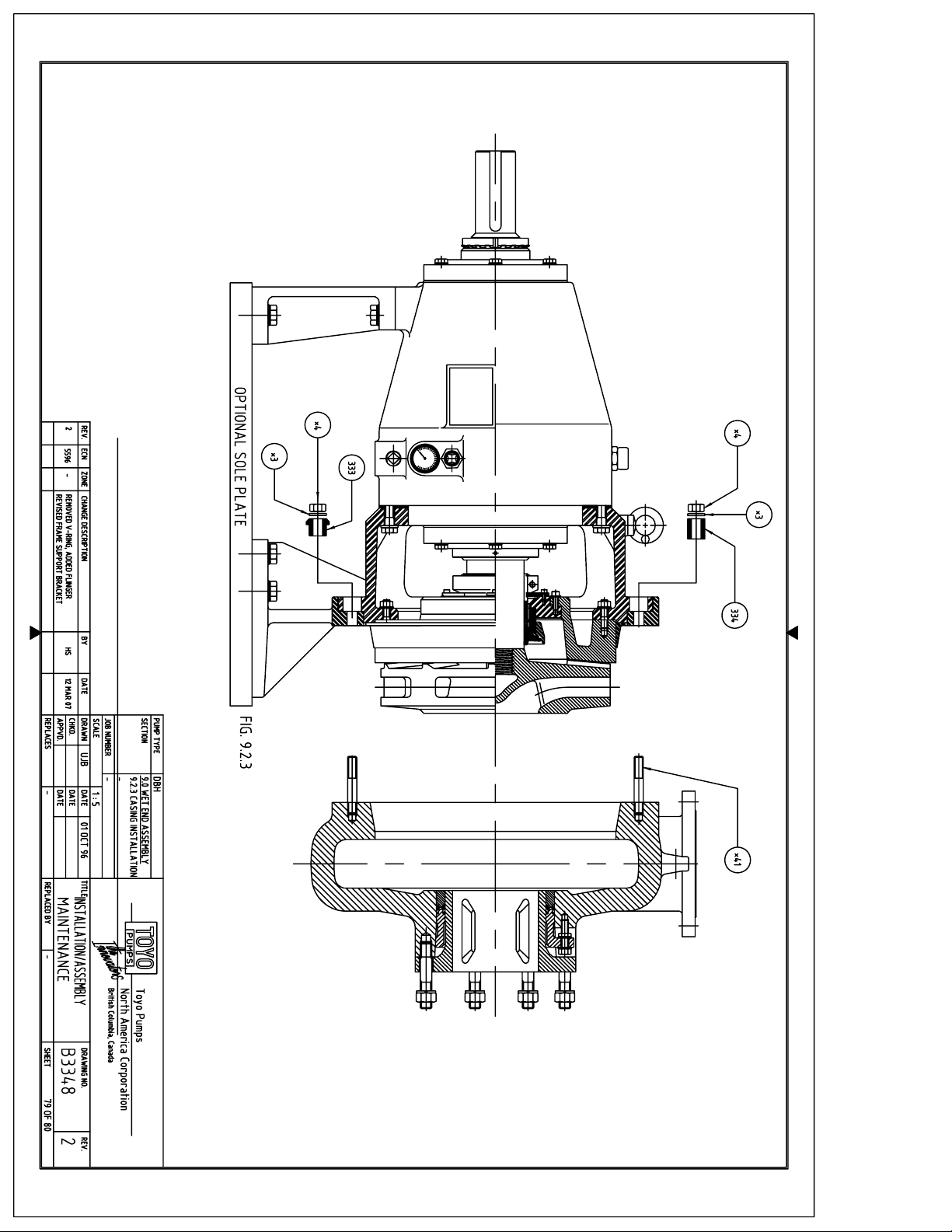
Page 83
TOYO PUMPS NORTH AMERICA CORPORATION
INSTALLATION, OPERATION AND MAINTENANCE MANUAL
TITLE: DBH INSTALLATION OPERATION AND
MAINTENANCE MANUAL
PREPARED BY: KSH RELEASE DATE: MAY 1 1997
APPROVED BY: SN REVISION DATE: MAR 15 2007
SUPERSEDES: REVISED BY:
9.2.3 CASING INSTALLATION
Refer to Drawing B3348
Using a chain or other suitable lifting sling placed thru the lifting eye, lift the casing off
of the floor into a vertical position.
CAUTION : CASING IS HEAVY, KEEP HANDS AND FEET CLEAR
Install the casing impeller side Studs (Item *41) into the casing. Wipe the inside of the
casing bore clean and apply a light coat of a silicone paste type lubricant to the bore
surface.
Double check that the casing inside wear face, wear ring face and suction throat liner
face are flush with each other.
Wipe the o.d. of the bearing side liner and casing seal clean and check the seal rubber
flange for proper seating.
Hoist the casing assembly in front of the bearing frame assembly and guide it over the
impeller and onto the bearing side liner.
Once the casing is seated against the seal rubber flange slide the Clamp Spacers (Item
334) and the Frame Clamps (Item 333) in an alternating fashion over the casing studs.
Install the Washers and Hex Nuts (Items *3, *4) onto the studs and tighten in a criss -
cross fashion to the required torque.
CAUTION : DO NOT REMOVE THE CHAIN OR LIFTING SLING UNTIL THE
CASING IS SECURED TO THE BEARING FRAME
DOCUMENT NO:
TED-039
REV. NO: 10
FROM UNDERNEATH
SHEET 80 OF 80
Page 84

TOYO PUMPS NORTH AMERICA CORPORATION
INSTALLATION, OPERATION AND MAINTENANCE MANUAL
TITLE: DBH MAINTENANCE OPERATION AND
INSTALLATION MANUAL
PREPARED BY: KSH DATE: MAY 1 1997
APPROVED BY: DATE: SUPERSEDES:
EFFECTIVE:
DOCUMENT NO:
TED-039 APPENDIX
PUMP SERIAL NUMBER:
REV. NO: PAGE 1 OF APPENDIX
APPENDIX
Page 85
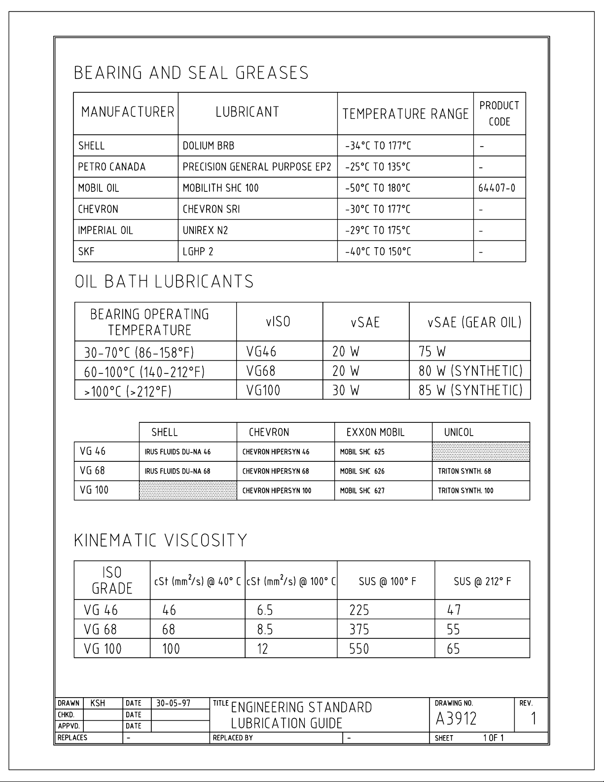
Page 86
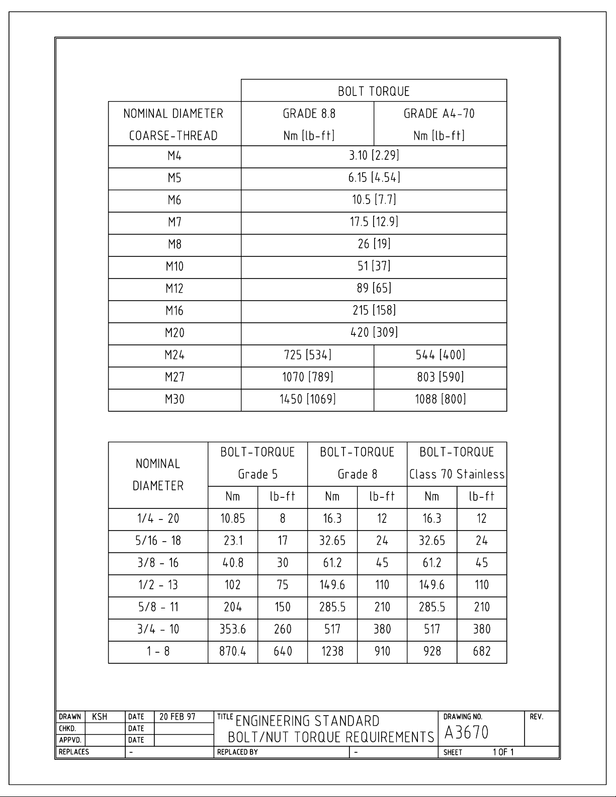
Page 87
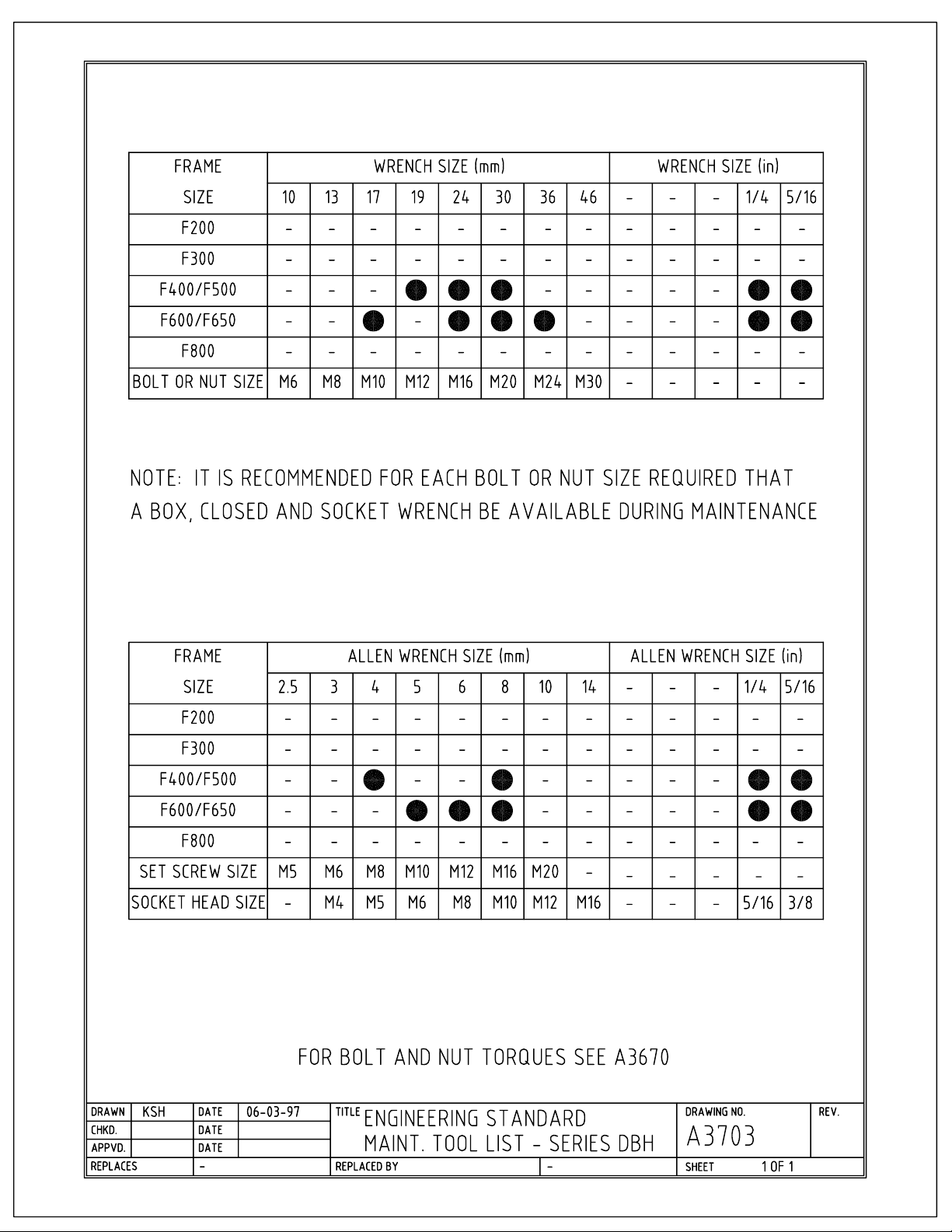
Page 88
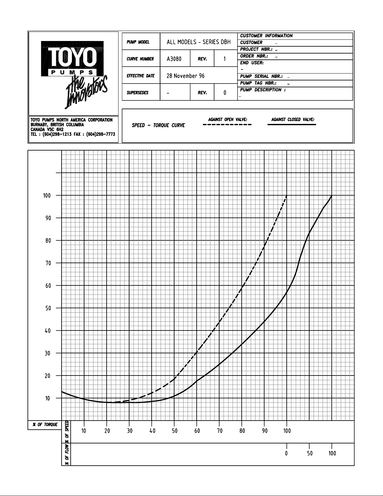
Page 89
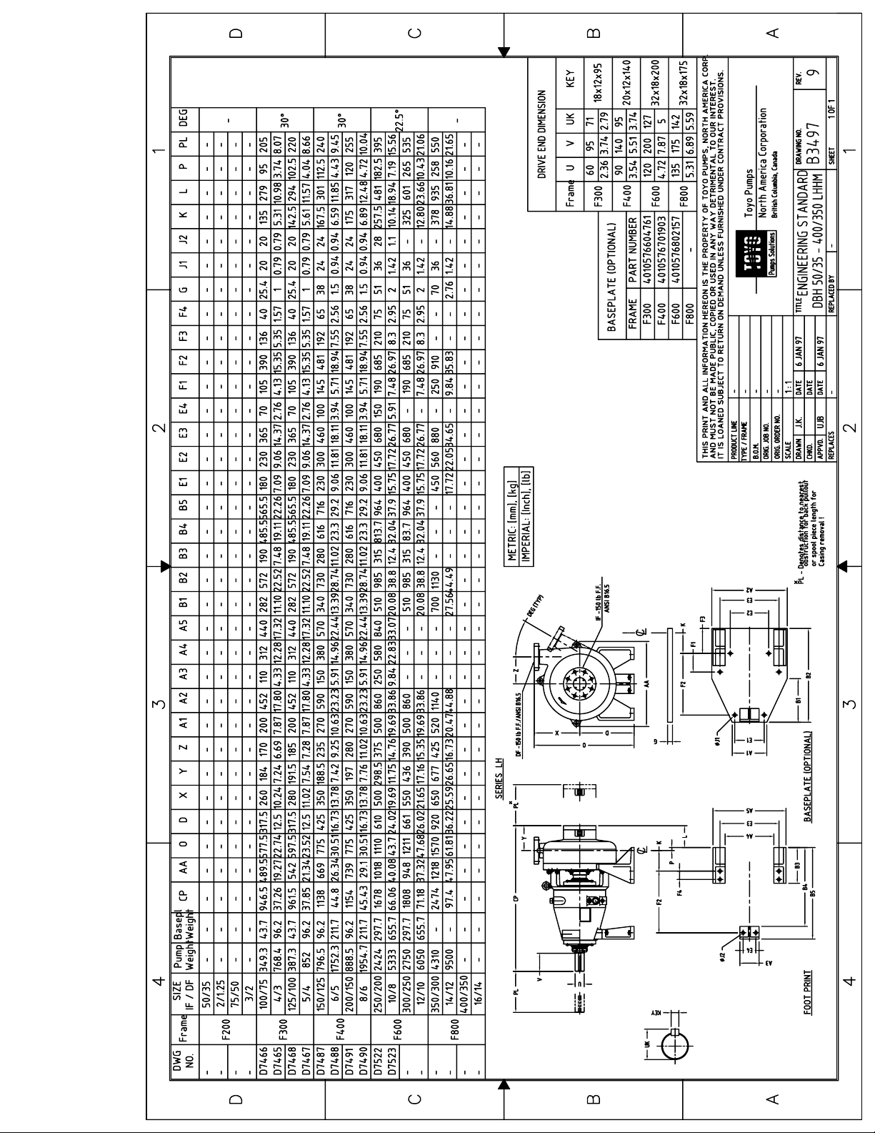
Page 90
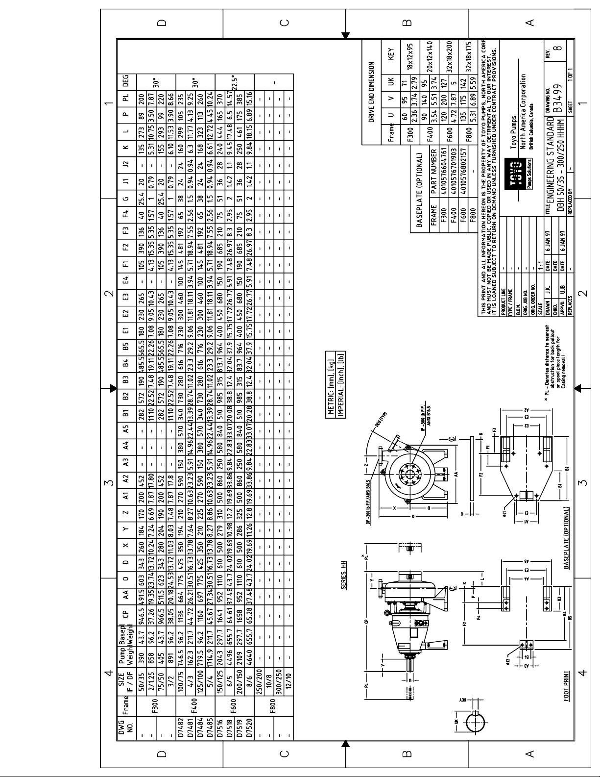
Page 91
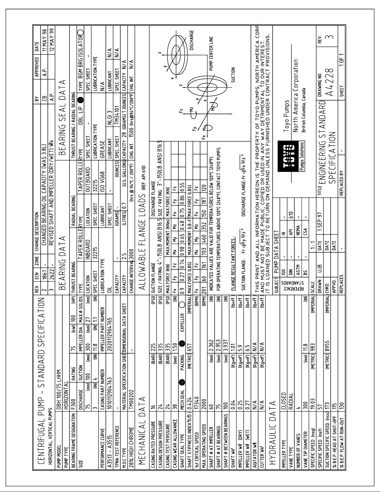
Page 92
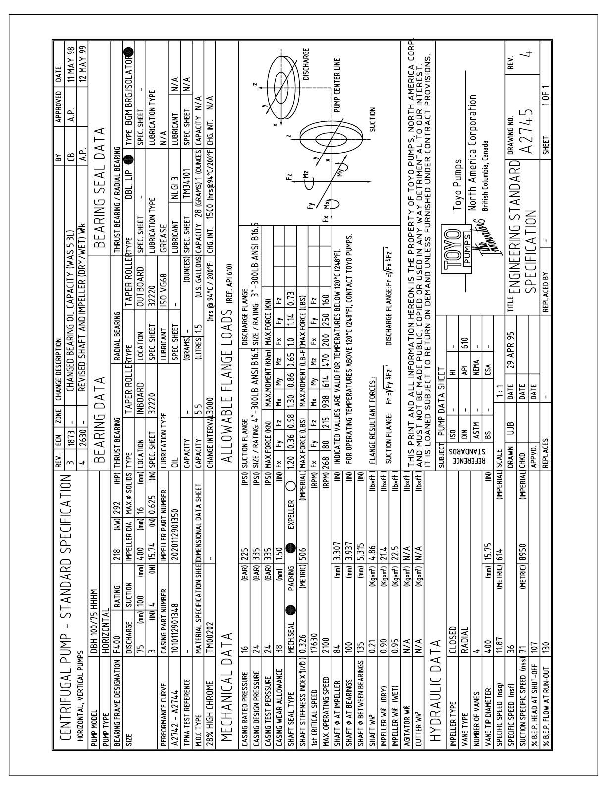
Page 93
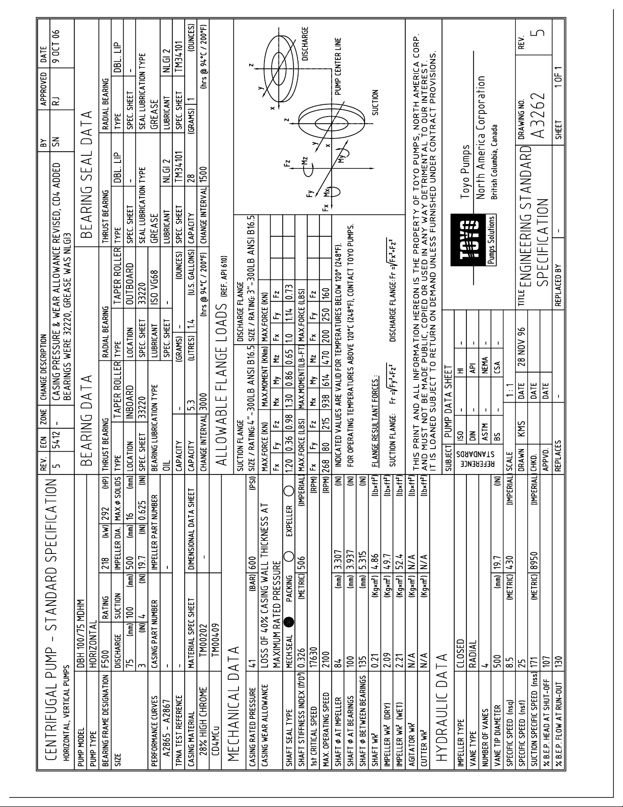
Page 94
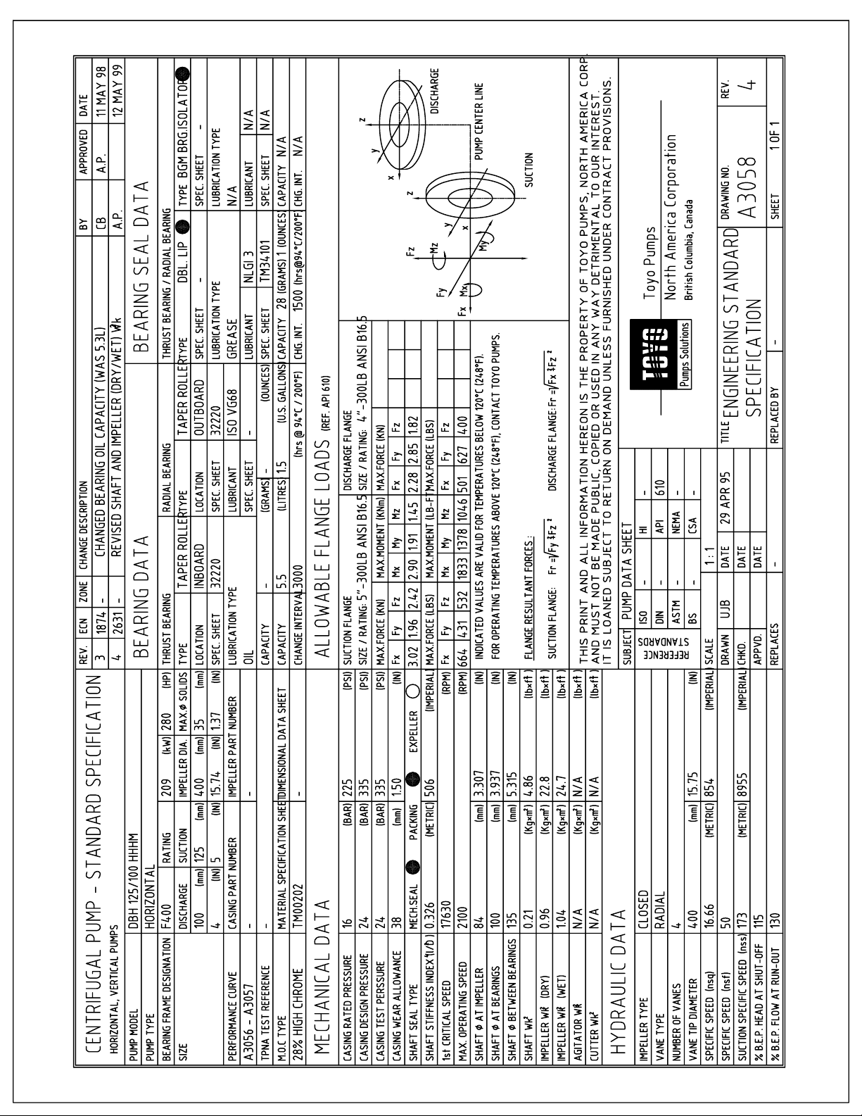
Page 95
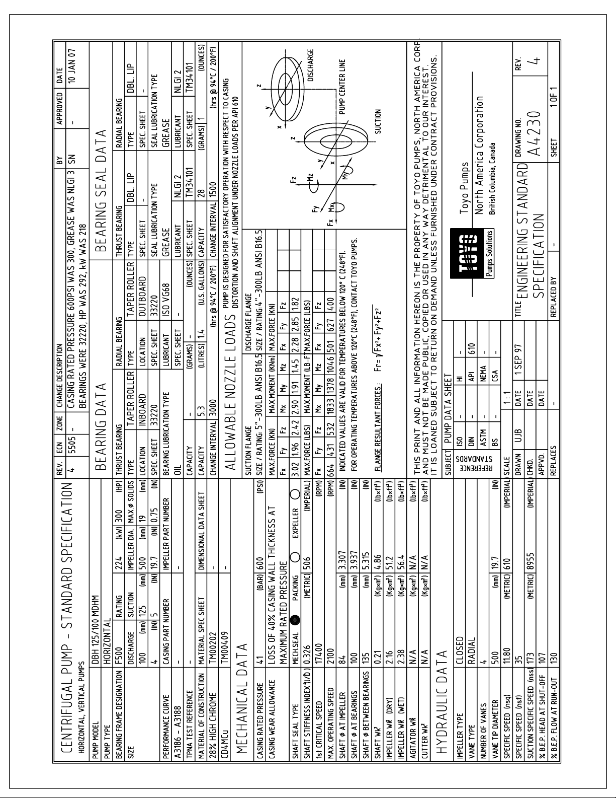
Page 96
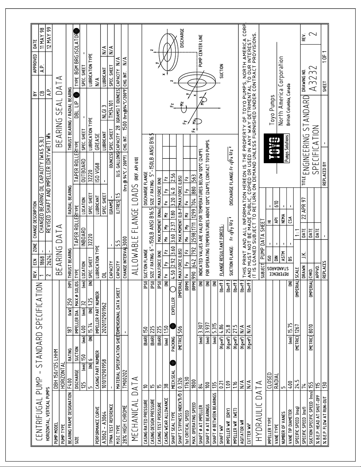
Page 97
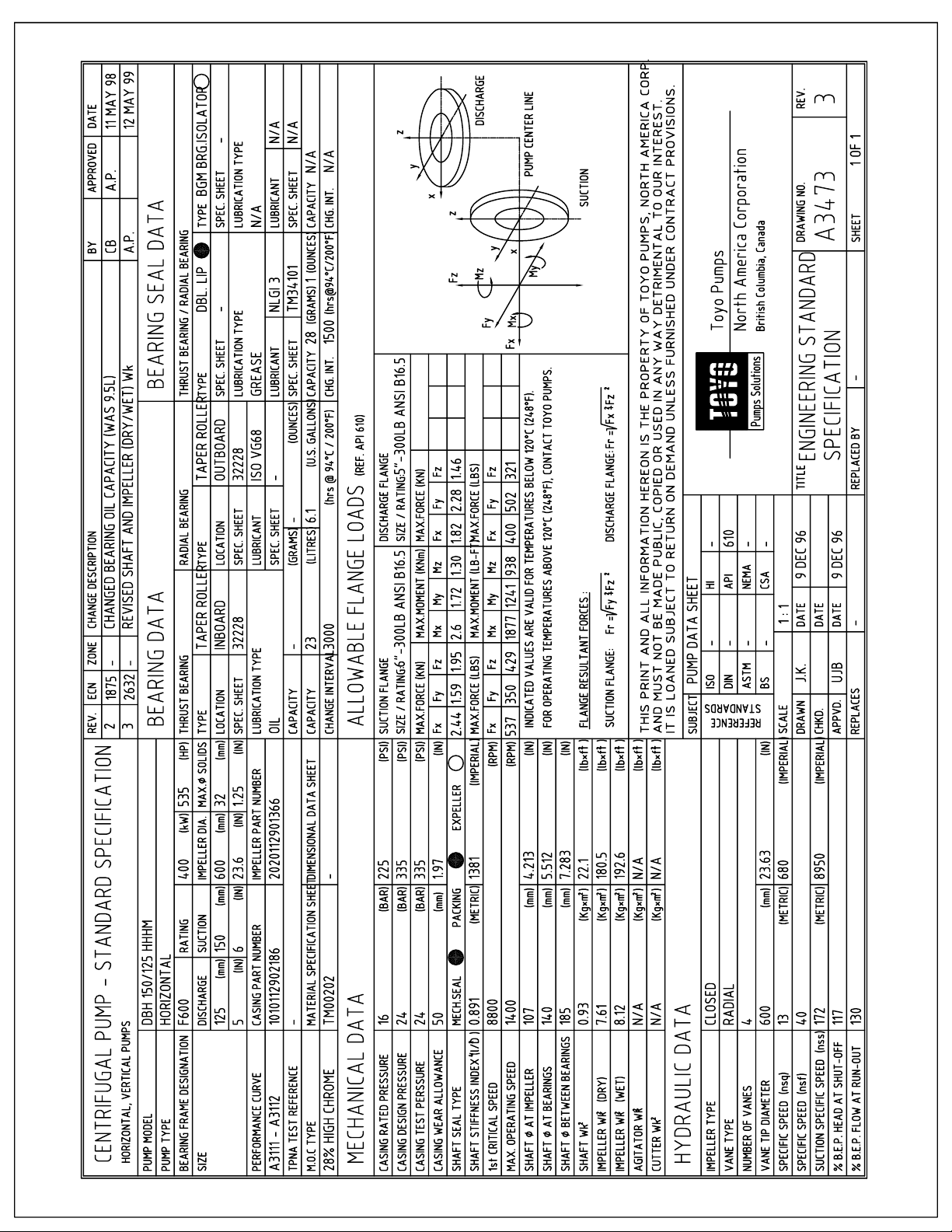
Page 98
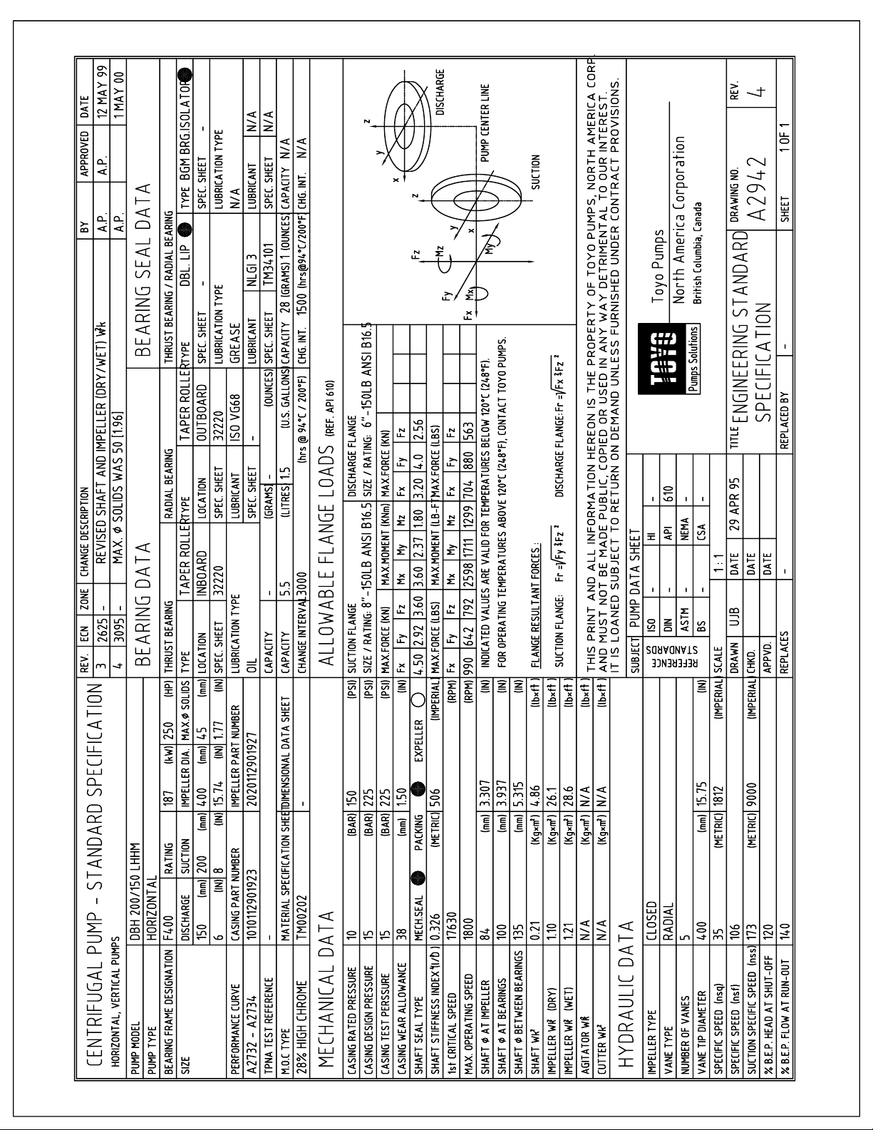
Page 99
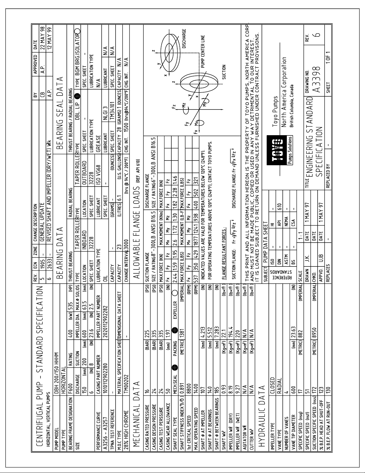
Page 100
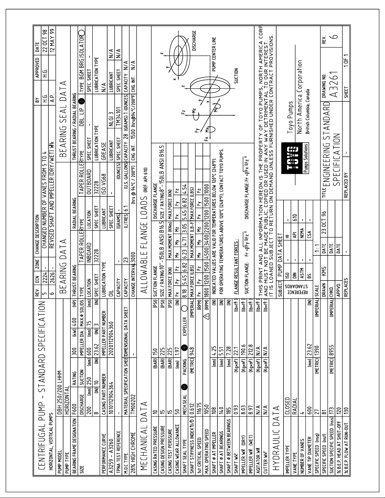
 Loading...