

ToyMonster Eezy Peezy Climber with Top Instruction Manual
1
4
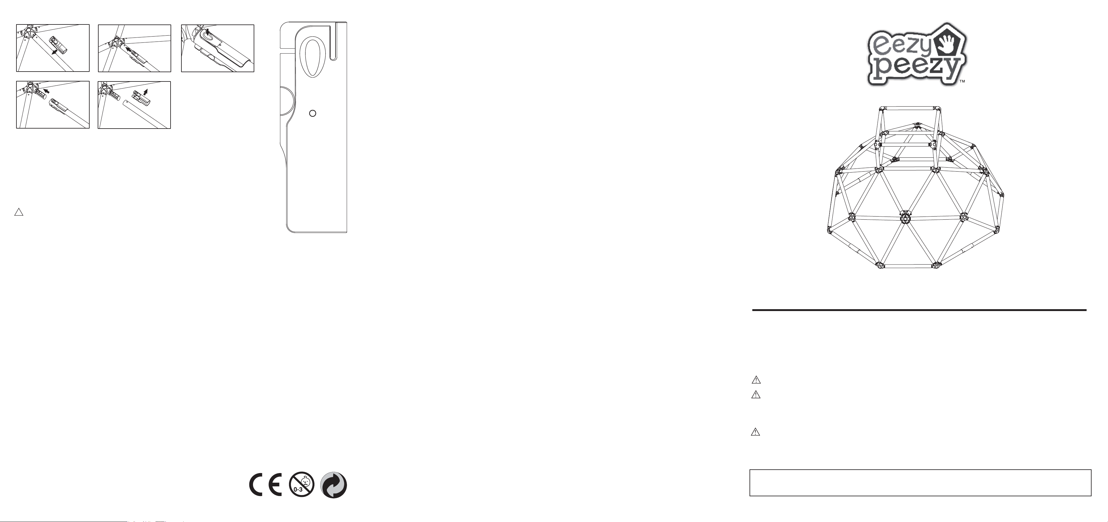
1. Attach the dismantle tool to the tube as shown in figure 1.
2. Move the tool along the tube, make sure the pivot inside the tube is aligned with the
spring bead on the tube as shown in figure 2.
3. Press the tool firmly until the spring bead is released from the tube as shown in figure 3.
4. Once the spring bead is released, separate the tube from the joiner as shown in figure 4.
5. Take out the tool as shown in figure 5.
!
WARNING!
Please always use the dismantle tool supplied for disassembly.
Otherwise the product maybe damaged by using other tools.
This tool can only be used maximum 2 times to dismantle the product.
Please dispose of the tool after 2 times use.
2
3
5
Climber with Top
Dismantle tool diagram
Actual size but
for reference only
DISPOSAL INSTRUCTIONS
Please always remember to disassemble and dispose of the playground equipment in such a way that no
unreasonable hazards will exist at the time the product is discarded.
LIMITED WARRANTY
The manufacturer warranties this product to be free of manufacturing defects for a period of ONE
year from date of purchase. This limited warranty does not cover normal wear and tear, or any
damage or failure caused by improper assembly, maintenance, storage or use of this product.
This Limited Warranty will be voided if this product is ever modified in anyway or used in any manner
other than for recreational use, or used as a rental.
The manufacturer does not offer an extended warranty. If you have purchased an extended warranty,
it must be honored by the store at which it was purchased.
This warranty is extended only to the original purchaser with a receipt and is non-transferable. Please
keep your receipt in a safe place.
Not suitable for children under
Manufactured by ToyMonster International Ltd.
5th Floor, No.16-2, Lane 658, Jin Zhong Rd.,
Chang Ning District, Shanghai, PRC.
Tel:+86-21-6238-5522 Fax:+86-21-5218-0520
E-Mail:cs@toymonster.net
www.toymonster.net
3 years due to small parts
Made in China
INSTALLATION INSTRUCTIONS
ALWAYS place the equipment on level ground, not less than 6.6 ft (2 m) from any structure or obstruction
such as a fence, garage, house, overhanging branches, laundry lines, or electrical wires.
This equipment should never be placed on hard surfaces such as concrete or asphalt or very soft surfaces. If
your child falls , serious injury may occur.
6KUHGGHGEDUNPXOFKZRRGFKLSs, fine sand or fine gravel are considered to be acceptable shock-absorbing
surfaces when installed and maintained at a sufficient depth under and around playground equipment.
However each material is only effective when properly maintained. Materials should be checked periodically
and replenished to maintain correct depth as determined necessary for your equipment. Otherwise serious
injuries may occur from a fall.
3OHDVHLQVWDOOWKLVHTXLSPHQWIDFLng away from the sun to avoid causing dizziness whilst playing.
Anchor applies to installation of this product in the clay (such as grass).This product must be anchored.
Please refer to instructions on how to anchor the equipment to prevent tipping, overturning, or lifting of the
support members during anticipated use. If the anchors are not assembled correctly, a fall or overturning onto
the ground can result in serious injury or death to the equipment user.
Consumer should install the product at the massive soil surface instead of the loose area, otherwise, the
anchor will deviate from surface easily pose overturn or fall injury.
The anchor must be inclined into the soil until it locks the tube which specified in the instruction manual.
To prevent serious injury, children must not use the equipment until properly installed.
OPERATION INSTRUCTIONS
Your children’s safety is our primary concern. Observing the following statements and warnings reduces the
likelihood of serious injury. Help us ensure years of safe, active play by reading and following these
recommendations.
1. The
8 years, with a total combined maximum weight of 70 kilograms. The maximum number of children using the
product at one time is 2.
2. Children must be supervised by an adult at ALL TIMES when using play equipment. Never allow children
under 3 years to play with this product for their safety.
3. DO NOT wear loose fitting clothing or shoes,(i.e. draw strings on hoods, mitten cords,hat strings, scarves,
helmets, ponchos or heavy necklaces). Children’s loose clothing can cause a potential danger of strangulation
while playing.
4. DO NOT walk close to, in front of, behind,or between moving equipment or children sliding.
5. DO NOT use this product in a manner other than intended.
6. DO NOT use this product when it is wet as it will become slippery and serious injury may result.
7. DO NOT attach additional items such as jump ropes, clothesline,pet leashes or other items not designed for
use with the playground equipment, as they may cause a strangulation hazard.
8. DO NOT allow objects to be placed under the product. Boxes, bicycles, trikes, toys or any other hard object
on the ground under the product will increase the risk of injury to children dropping to the ground.
9. Be certain that all anchoring devices are placed below the level of the playing surface or below ground level
to prevent tripping.
10. DO NOT let children use this product until properly assembled and anchored. Place this product on LEVEL
GROUND not less than 6.6 feet(2m) from any structures or obsta
laundry or electrical lines, garages, sheds or houses.
11. DO NOT allow the use of plastic items when the temperature drops below 32 degrees F, (0 degree C).
12. Dispose of all packaging properly after unit has been assembled.
13. DO NOT install this product over concrete, asphalt or any other hard surface. A fall onto a hard surface can
result in serious injury to the product user.
Climber with Top is designed for children of the ages of not less than 3 years and not greater than
cles such as fences, overhanging branches,
MAINTENANCE INSTRUCTIONS
3OHDVHFRUUHFWO\DVVHPEOHWKLVSURGXFWDVSHUWKHLQVWUXFWLRQVRWKHUZLVHLWZLOOFDXVHGDQJHUWR\RXUFKLOG
Take this product indoors or do not use when the temperature drops below 32 degree F,(0 degree C).
&KHFNDOOMRLQHUVDQGWXEHVEHIRUH use every time for cracking or deterioration. If either the joiners or the
tubes are cracked or damaged please replace the damaged part immediately. Replacement should be made in
accordance with the instructions. If these checks are not carried out the product could overturn or cause a fall.
&DUU\LQJRXWFKHFNVDQGPDLQWHQDnce of the main parts at regular intervals, if these checks are not carried
out the toy could overturn or otherwise become a hazard.
,WLVRISDUWLFXODULPSRUWDQFHWKDWWKLVSURFHGXUHEHIROORZHGDWWKHEHJLQQLQJRIHDFKVHDVRQDVZHOODVDW
regular intervals during the usage season:
Check all nuts and bolts twice monthly during the usage season for tightness and tighten as required.
Check all coverings for bolts and sharp edges twice monthly during usage season to be certain they are in
place. Replace when necessary.
'RQRWLQFUHDVHWKLVWR\DFFHVVRULHV
English
CLIMBER WITH TOP
MB-CB-BG
Instruction Manual
Please read carefully before assembly and use
The eezy peezy Climber with Top is lightweight, easy to assemble and transport.
Adult supervision and installation required. See instructions for proper installation and maintenance.
Warning:
Warning: prior to assembly, this package contains small parts, which are a choking hazard and
may contain sharp edges and sharp points. Keep away from children until assembled. Adult assembly
required.
Warning:
intended for children under 3 years due to lack of ability to operate safely. Has the capacity to hold
a maximum number of 2 children at one time with combined weight of 70 kilograms.
Remember: Please inspect your Climber with Top every time before use for any signs of
deterioration. If the tubes or joiners are cracked or damaged please replace the part immediately.
Please keep this booklet in a safe place for future reference.
For outdoor family domestic use only.
This product is intended for use by children from ages 3 years to 8 years and is not
English
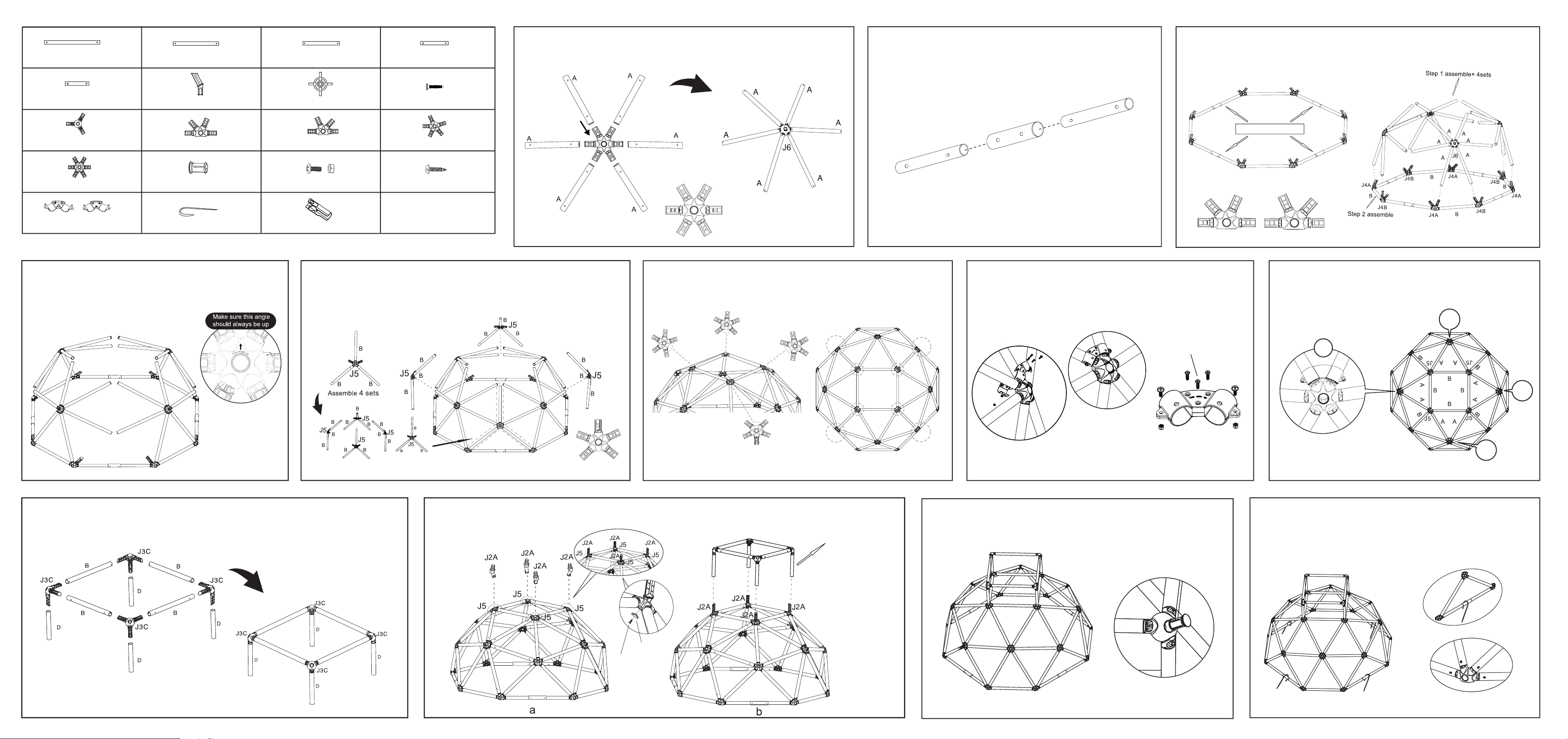
x 8
A=524mm tube(Longest Tube)
x 24
x 24
B=481mm tube C=351mm tube D=240mm tube
x 4 x 4 x 4 x 4
E=140mm tube(Shortest Tube) J2A= 2 arm joiner Joiner cover Self-Locking Screw (ST3.5x15)
J3C=3 arm joiner with equal distance
between arms
J6=6 arm joiner N cover
Tube Clips
x 4
J4A=4 way joiner J4B=4 way joiner(mirror image of J4A) J5=5 arm joiner
x 4
x 4
x 20
x 4 x 4
Anchor
Screw & Bolt Self-Locking Screw(ST4.2×12)
Dismantle tool
x 4
x 8
x 1
Please note all tubes have stickers on them for easy identification.
Step 4: Assemble the 4 sets of J6 joiners with 6 A tubes
assembled from Step 1 to the base circle. Please make sure
that the A tubes of J6 joiners connect to the joiner on two sides
of the B tube on the base circle. Please refer to figure 4 for
details and illustration.
A
J6
A
A
A
A
A
B
Figure 4
Step 5: Assemble the J5 joiner to the two A tubes and assemble the other 3
arms of the J5 joiner with B tubes as shown in figure 5. The other end of the B
tube will connect with the J4A and J4B joiners on the base circle.
Please assemble 4 J5 joiners as shown in figure 5 to form a full circle.
A
x 4
x 8
x 12
A
A
Step 1: Assemble 6 x A tubes to 1 x J6 joiner as shown in figure 1.
Repeat this three times to make this a total of 4 sets.
Step 2: Take one E tube and slot a C tube on either side as shown
in figure 2. Repeat this 4 times to assemble a total of 4 sets.
Step 3: Take the tubes assembled in step two, and 4 x J4B joiners, 4 x J4A joiners,
and 4 x B tubes. Assemble them together as shown in figure 3.
J4B
B
J4A
C
Insert
J6
C
A
A
A
A
AA
Assemble 4 sets
Figure 1
Step 6: Assemble a new J5 joiner with arm in the center to the open
end of B tube and other two arms to the A tubes. Then assemble 2 new
B tubes to the 2 open arms of the J5 joiner. Assemble 4 J5 joiners to
form a square on the top.as shown in top view of figure 6.
J4A
E
Figure 2
B
J4B
A
B
C
J4A
Step 7: Assemble a pair of tube clips to the two A tubes that
extend from the top of the J6 connector and connect to the corners
of the square on top. Insert 3 Self-Locking Screws (ST4.2×12) & 2
pairs of bolts & screws to the tube clips and screw tightly as shown
Figure2 assembledtube
B
J4A
B
B
J4B
Step 8: Please make sure that the 4 pairs of tube clips are
assemble to the four triangles configurated by 2 tube A, 1 tube B
on the top square respectively. Please refer to figure 8 for an
illustratiion.
J4B
A
B
C
J4B
B
J4A
Figure 3
in figure 7. Repeat this step at all the locations as shown in Step 8.
B
A
A
J5
B
B
A
B
B
A
B
90°
J5
A
B
A
J5
B
A
B
B
A
A
B
B
J5
Figure 5
90°
B
B
B
B
J5
90°
B
B
A
A
B
J5
A
B
B
A
B
90°
J5
J5
J5
B
J5J5
A
A
B
J5
A
A
A
B
B
B
A
A
BB
A
B
J5
J5
J5
Top view
Figure 6
Self-Locking Screw
(ST4.2×12)
Figure 7 Figure 8
4
1
2
3
Top view
Step 9: To build the tower. Assemble a square using J3C joiners and B tubes as shown in
figure 9. Assemble 4 x D tubes to 4 X J3C joiners.
Figure 9 Figure 10
Step 10: Attach a J2A joiner to J5 as indicated in figure 10a. Assemble the joiner covers to the J2A joiners with
Self-Locking Screw(ST3.5x15) as shown in figure 10a. According step 9, assemble them together as shown in
figure 10b.
joiner cover
Self-Locking Screw
(ST3.5x15)
Step 9 assemble
Step 11: Assemble the N covers to the holes in the joiners as shown
in figure 11.
Figure 11
Step 12: Hammer the anchors into the ground at 45 degrees to gain
maximum stability as shown in figure 12a. Make sure all the tubes fix
firmly to the joiners. Check and make sure all the springs in the joiners
go into the tube as shown in figure 12b.
a
b
Figure 12
 Loading...