

Page 1
™
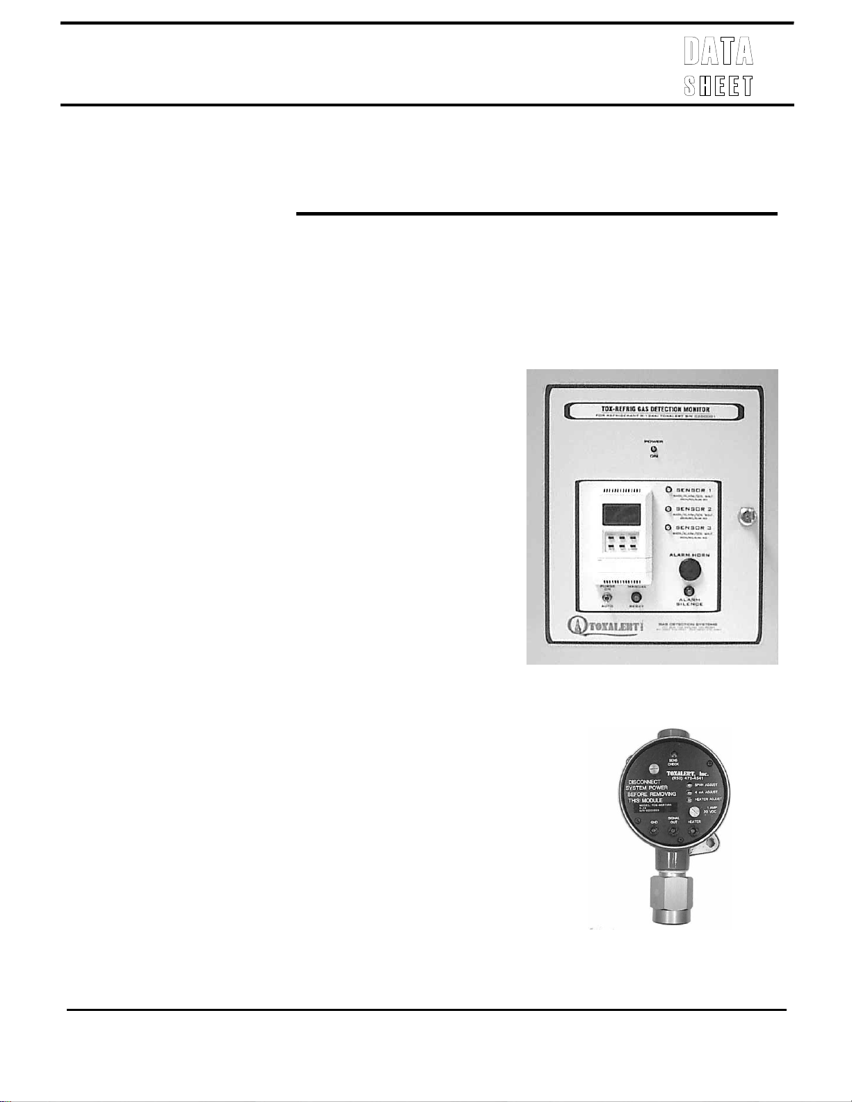
TOXALERT’S Model TOX-REFRIG Refrigerant Leak
Monitoring System consists of a remote refrigerant sensor
or sensors and a controller/annunciator panel. The TOXREFRIG system is designed to continuously monitor
mechanical refrigeration equipment rooms for refrigerant
leaks and upon detecting a leak, the unit shall start
ventilation equipment and annunciate alarm conditions.
ANSI/ASHRAE Standard 15-2010 calls for the use of
refrigerant leak detectors.
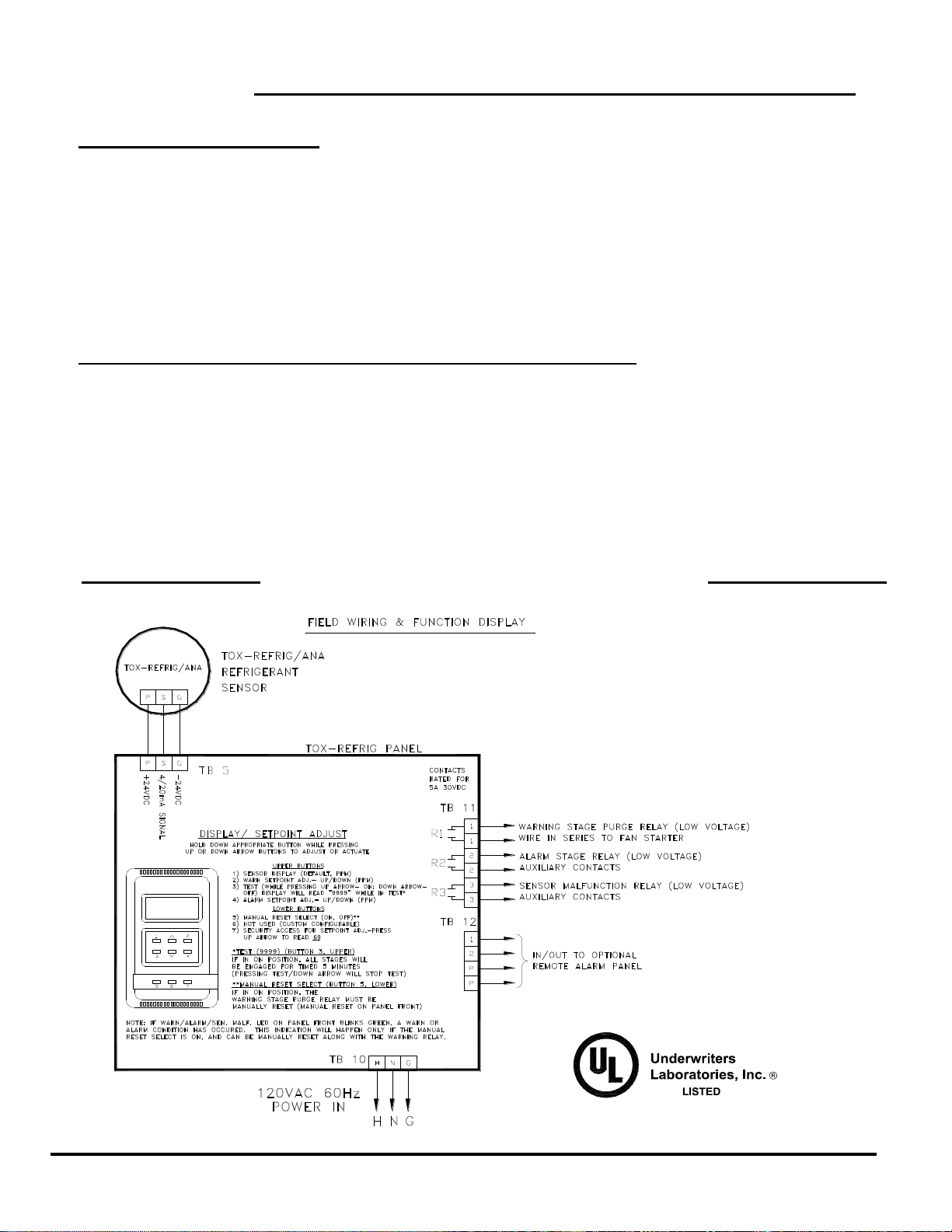
The controller’s first stage or “Warning (Purge) Stage”
activates a set of relay contacts to operate exhaust fan(s) or
other mechanical equipment, and the sensor LED on panel
front will light green. The second stage or “Alarm Stage”
activates an audible alarm with reset and silence
pushbutton switch, an auxiliary set of relay contacts, and
the sensor LED on panel front will light red. On a
decrease in refrigerant concentration, the alarm stage
automatically resets and the warning stage is field
selectable for manual or automatic reset- (manual reset
select). If the manual reset select option is turned on and
the sensor detects a warning or alarm condition, the
warning relay will remain activated and the sensor LED on
panel front will blink green, even after the concentration
has decreased. That function can be manually reset via a
reset button located on panel front.
A “Purge” switch on the controller front has two positionsON & AUTO. In the AUTO position, the warning stage
relay energizes automatically from sensor monitoring; in
the ON position, the warning contacts are manually
energized.
TOXALERT
REFRIGERANT MONITOR MODEL: TOX-REFRIG
MECHANICAL ROOM REFRIGERANT LEAK
DETECTION SYSTEM
TYPICAL APPLICATIONS:
Mechanical Rooms in:
Commercial Buildings
College/Universities
Hospitals
Sports Facilities
Refrigerant Warehouses
GENERAL DESCRIPTION:
TOXALERT INTERNATIONAL, INC., P.O. BOX 159, MOUND, MINNESOTA 55364 • 952/472 -4541 • 952/472-4960
Industrial Chemical Plants
Resorts
Supermarkets
Blood Banks
Tox-Refrig
Tox-Refrig/ANA
www.toxalert.com
Page 2

The remote refrigerant sensor(s) is continuously monitored by the controller for sensor failure. If the
sensor malfunctions, the controller shall cause the sensor LED to blink red, and activate the warning stage
relay as well as a sensor malfunction relay contact.
FEATURES
Warning (purge) stage indication
Alarm stage indication
Sensor malfunction indication
Relay outputs for control of ventilation
equipment and remote alarming (Warn,
Alarm, Sensor Malfunction)
Optional auxiliary relay contacts for
shutdown of combustion equipment
Operation meets ANSI/ASHRAE 15-2010
Digital readout (Refrigerant in PPM)
Field adjustable setpoints with security
Test function
Field selectable warning stage reset
(manual/auto)
Audible alarm (integral to control unit)
Interface to automation system (digital and/or
optional analog)
Multiple sensor inputs (optional)
Remote Alarm Capabilities
BACnet MS/TP Protocol
Optional Strobe Light
MECHANICAL ROOM REQUIREMENTS
In the Forward of ASHRAE Standard 15-2010, it states in part, “All machinery rooms are required to have detectors
that actuates an alarm and mechanical ventilation at a value not greater than the corresponding TLV-TWA (or
toxicity measure consistent therewith”. ASHRAE Standard 15-2010, section 7 & 8 requires detectors to monitor for
refrigerant leaks. The standard reads as follows:
Paragraph 8.11.2.14 reads-
“Each machinery room shall contain a detector, located in an area where refrigerant from a leak will
concentrate, that actuates an alarm and mechanical ventilation in accordance with 8.11.4 at a value not
greater than the corresponding TLV-TWA (or toxicity measure consistent therewith).”
Paragraph 8.11.6
“Combustion equipment shall not be installed in the same machinery room with refrigerant containing
equipment except under one of the following conditions:
(b) a refrigerant detector ….. is employed to automatically shut down the combustion process in the
event of refrigerant leakage.
Exception: For ammonia refer to paragraph 8.12(h).
SENSOR LOCATION:
ASHRAE Std. 15-2010- “locate in an area where refrigerant from a leak will concentrate” is very ambiguous and for
good reason. There are a wide variety of equipment room configurations and sizes.
A few keys to locating refrigerant sensors are: (1) remember that occupant safety is the primary motive for installing
the sensor; (2) determine the air flow pattern in the room; (3) the primary hazard of a refrigerant to a room occupant
is the inhalation of the toxic refrigerant.
TOXALERT INTERNATIONAL, INC., P.O. BOX 159, MOUND, MINNESOTA 55364 • 952/472-4541 • 952/472-4960
www.toxalert.com
Page 3
Refrigerant
Name
TLVTWA
(a)
PPM
Refrigerant
Name
TLVTWA
PPM
Safety Group A1
(b)
R-11
Trichoroflouremethane
1100
R-402A
R-125/290/22
1000
R-12
Dichlorodifluoromethane
18000
R-404A
R-125/143a/134a
1000
R-13
Chlorotrifluoromethane
1000
R-407C
R-32/125/134a
1000
R-13B1
Bromotrifluoromethane
1000
R-410A
R-32/125
1000
R-14
Tetrafluoromethane (Carbon
Tetrafluoride)
1000
R-500
R-12/152a
1000
R-22
Chlorodifluoromethane
1000
R-502
R-22/115
1000
R-113
Trichorotrifluoroethane
1000
R-503
R-23 & R-13
1000
R-114
Dichlorotetrafluoroethane
1000
R-507
R-125 & R-143a
1000
R-115
Chloropentafluoroethane
1000
R-740
Argon
…..
R-134a
1,1,1,2-Tetrafluoroethane
1000
R-744
Carbon Dioxide
5000
Safety Group A2
(b)
R-142b
1-Chloro-1, 1-Diflurorethane
1000
R-152a
1,1-Difluroethane
1000
Safety Group A3
(b)
R-170
Ethane
1000
R-600a
2-Methyl propane
(Isobutane
1000
R-290
Propane
1000
R-1150
Ethene (Ethylene)
200
R-600
Butane
1000
R-1270
Popene (Propylene)
500
Safety Group B1
(b)
R-123
2,2-Dichlor-1, 1,1-Triflurooethane
50
R764
Sulfur Dioxide
…..
Safety Group B2
(b)
R-40
Chloromethane (Methyul
Chloride)
…..
R-717
Ammonia
25
R-611
Methyl Formate
100
Mounting height of refrigerant sensors should be within 20 inches of the floor. The Forward of Std. 15-2010 states ,
“(all commonly used refrigerants, except ammonia (R-717)….. are heavier than air).” By placing the sensor below the
common breathing height of 5 to 6 feet, you will provide and added margin of safety.
Floor Plan Location- If ventilation equipment is running continuously, the sensor should be located between the
refrigeration system and room exhaust, as close to the refrigerant equipment as possible. One sensor will usually be
adequate for applications with two (or less) chillers, provided chillers are aligned for good air flow and both chillers use
the same refrigerant. If ventilation equipment is NOT running continuously or if the direction of airflow is not obviouslocate the sensor(s) next to the refrigeration system. As a general guideline, a refrigeration system should not be more
than 50 feet from a refrigeration sensor.
NOTE: See Toxalert Technical Bulletins- “ToxRefrig InstRec- Section 5 (of the product catalog)”.
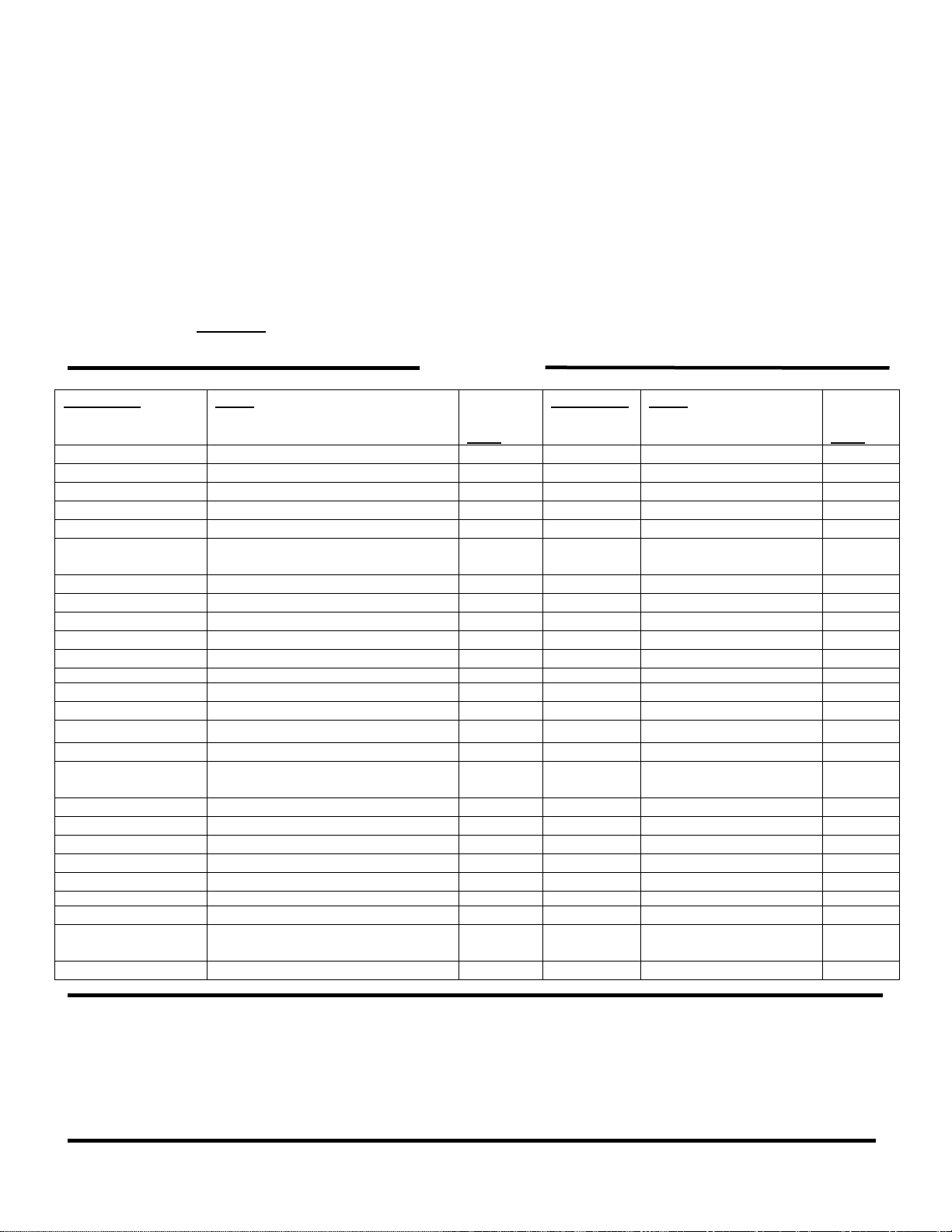
The following is a partial list of refrigerants that Toxalert monitors.
TABLE 1
(a) threshold limit value time weighted average: the time – weighted average concentration for a normal 8-hour
workday and a 40 hour work week to which nearly all works may be repeatedly exposed, day after day, without
adverse effect (as defined by ACGIH®). TLV® is a trademark of the American Conference of Governmental
Industrial Hygienists (ACGIH®).
(b) Defined by ANSI/ASHRAE Standard 34-2010
Note – See Toxalert Technical Bulletin Refrig for more information on refrigerant classifications.
TOXALERT INTERNATIONAL, INC., P.O. BOX 159, MOUND, MINNESOTA 55364 • 952/472-4541 • 952/472-4960
www.toxalert.com
Page 4
TOX-REFRIG REVISED 2/12
TOX – REFRIG MONITOR
SPECIFICATIONS
TOX-REFRIG CONTROLLERInput Power: 120VAC, 60Hz, 1 Amp(fused)
Warning Setpoint: Field adjustable, factory set
Alarm Setpoint: Field adjustable, factory set
Warning Stage: Visual indication, Form C relay contacts
Alarm Stage: Visual indication, Form C relay contacts
Sensor Malfunction: Visual indication, warning stage
activation, and separate Form C relay contacts
Digital Readout: 3 1/2 digit, red LED, in PPM
TOX-REFRIG/ANA SENSOR: (specs for most Toxalert refrigerant sensors) ─ [Order Sensor Separately]
Relay Contacts: Rated for 5 Amps @ 120VAC, resistive
load
BACnet: MS/TP communications
Operating Range: 32°F to 120°F (0°C to 49°C)
Mechanical:
Dimensions:14”H x 12”W x 4”D
Classification: NEMA 1
Weight: 12 lbs
Method: Semiconductor cell diffusion barrier
type
Range: 15 to 500 PPM
Response: 90% of concentration in less than 30
sec.
Operating Range:
Temp: 14°F to 104°F. (-10°C to 40°C)
Humidity: 5 to 95% non-condensing
Typical Life: Four years in normal service
Maintenance: Periodic calibration
Mechanical:
Dimensions: 6.75”H x 4”W x 3.5”D
Material: Cast aluminum epoxy painted
Classification: Class I Division I Groups
C, D
Weight: 2 lbs.
TOXALERT INTERNATIONAL, INC., P.O. BOX 159, MOUND, MINNESOTA 55364 • 952/472-4541 • 952/472-4960
www.toxalert.com
 Loading...