

Page 1
TM
CARBON MONOXIDE (CO) ANALOG MODEL Tox CO/ANA
SENSOR FOR EMS/DDC SYSTEMS
TYPICAL INSTALLATIONS:
• Parking Garages • Warehouses
Apartments • Tunnels
Condominiums • Factories
Office Buildings • Car Dealers
• Bus Garages • Airplane Hangers
• Maintenance Garages • Maintenance Shop
• Fire Stations • Etc.
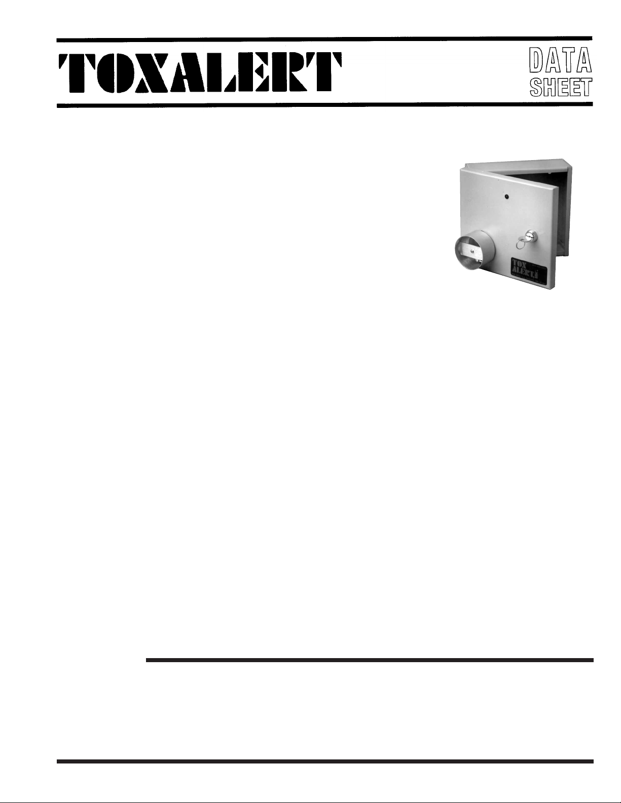
SENSOR
GENERAL DESCRIPTION:
The TOXALERT INTERNATIONAL Model Tox-CO/ANA measures carbon monoxide concentrations
over its range of operation and provides a corresponding 4 to 20 milliamp linearized output signal.
The Model Tox-CO/ANA is the first sensor system to be priced well below laboratory type devices. This low
cost breakthrough opens a new set of applications previously unattainable. This is especially significant in
light of today’s growing concern regarding indoor air quality and increased costs of heating and cooling
energy.
The Model Tox-CO/ANA may be used in many applications. By monitoring gas concentrations, you may
control ventilation equipment and/or alarm at user defined levels of CO.
Because of potential energy savings, it is very advantageous to control the ventilation equipment of confined spaces where CO is being produced (ie: enclosed parking garages, warehouses, etc.) In these types of
facilities, codes require the continuous running of ventilation equipment, unless a CO monitoring system is
employed (see background section).
The model Tox-CO/ANA supplies the carbon monoxide concentration information to any controller that
can utilize a 4 to 20 mA signal. The controller, whether automation, direct digital, or Toxalert contoller, may
be programmed to control the ventilation fans, trend log the concentrations, or alarm at user programmable
concentrations. The Tox-CO/ANA may be used with Toxalert’s Tox-4ANA’s and ToxControl analog input
controllers to digitally display the ambient CO level being sensed, operate ventilation equipment, and sound
an alarm on persistent high levels of CO. With the ToxControl controller a printer option is available to
record time and date of fan operation for each sensor, record alarm data and print out custom alarm mes-
sages.
FEATURES:
• Analog output: linear 4 to 20 mA
signal.
• Operating range meets OSHA
ventilation requirements.
• Low voltage class 2 wiring.
• Solid State sensor.
TOXALERT INTERNATIONAL, INC., P.O. BOX 159, MOUND, MINNESOTA 55364 (952) 472-4541 FAX (952) 472-4960
• Microprocessor based 12 bit analog to
digital conversion resolution.
• Optional digital display for CO
level in PPM (parts per million).
• Automatic calibration.
• Selective to Carbon Monoxide.
Visit our website at www. toxalert. com
• Performance indicators
(LED’S) for:
- Power on
- System operating normally
- Automatic calibration
• UL listed components.
• Multiple ranges available.
Page 2

BACKGROUND:
Codes require that the ventilation fans run continuously in enclosed parking areas unless a carbon
monoxide monitoring system is employed to control the fans.
Uniform Building Code Section 705 - In all parking garages, other than open parking
garages as defined in Section 709 (b), used for storing or handling of automobiles operating under their own power and on all loading platforms in bus terminals, ventilation shall
be provided capable of exhausting a minimum of 1.5 cfm per square foot of gross floor
area. The building official may approve an alternate ventilation system designed to exhaust a minimum of 14,000 cfm for each operating vehicle. Such system shall be based
upon the anticipated instantaneous movement rate of vehicles but not less than 2.5 percent
(or on vehicle) of the garage capacity.
Automatic CO sensing devices may be employed to modulate the ventilation system to maintain a maximum average concentration of CO of 35 ppm during any
eight-hour period, with a maximum concentration no greater than 200 ppm for a
period not exceeding one hour.
Therefore, especially in colder climates, it is advantageous to install a CO system.
ings
occur merely in the power needed to run the fans, but also, limiting the introduction of cold
up
air will reduce the overall heating (and in some cases cooling) requirements.
Not only would a sav-
make-
PRODUCT DESCRIPTION:
The Model Tox-CO/ANA uses the most current techology in sensors and electronics resulting in a stable
and long life unit. The heart of the electronics is a microprocessor with 12 bit analog input resolution and
8 bit analog output resolution.
The Model Tox-CO/ANA uses tin oxide semiconductor technology for carbon monoxide sensing. These
sensors are internally heated to sense gas. In the Model Tox-CO/ANA the heater is microprocessor
cycled to enhance the detection of carbon monoxide over other background gases. Readings are taken
every two and one half minutes at the end of heating cycle. Then the sensor is heated to a higher temperature for self cleaning. After the cleaning phase, the sensor is returned to the sensing temperature.
The heater current is microprocessor controlled and monitored to compensate for any long term drift in
the sensors internal parameters to ensure long term stability and repeatability of readings.
Since the tin oxide technology sensor is sensitive to the ambient gas temperature and humidity, compensation for gas temperature and humidity are included in the operating software of the microprocessor.
Factory calibration is performed in a triple point technique, at 50, 200 and 400 ppm of carbon monixide
concentrations with normal temperature and humidity. The software in the Model Tox-CO/ANA automatically compensates the output signal for changes in ambient relative humidity and temperature. Calibration can be checked at any time by using the optional field calibration check kit. This kit utilizes a
known CO gas sample.
The microprocessor system includes self diagnostic, self restarting, and remote failure reporting. The
self diagnostics allow the microprocessor to determine that the entire software code is 100% intact upon
power up and at other periodic intervals. If there were a failure in the code, the model Tox-CO/ANA will
lower the output signal below 4 milliamps to signal the controller using the signal that maintenance is
required. The same lowering of the output signal occurs should the microprocessor determine a failure in
any other components in the system including the carbon monoxide sensor itself. In the event that a
severe electrical disturbance occurs that caused the Model Tox-CO/ANA to malfunction, the microprocessor will restart without human intervention, and if all code is found to be intact, will resume normal
operation. The Model Tox-CO/ANA is also tolerant of power line transients.
The Model Tox-CO/ANA shows its operating status with several LED (light emitting diode) indicators.
Indicators used are: +5V power on, +15V power on, system operating normally, and system in calibration.
The Model Tox-CO/ANA is designed for easy installation. The electronics and sensor are removable
from the cabinet as one unit for easy shipping and installation. The Tox-CO/ANA is mounted in a metal
cabinet with a hinged, key locking door.
Page 3

SPECIFICATIONS:
• Output Signal: 4 to 20mA; into
500ohm load max.; 250 ohms nominal.
• Scale; 0 to 400ppm Carbon Monoxide
linear (other ranges 0-100, 0-200).
• Environmental:
Operating -
Temperature: -20˚ F to 122˚ F
(-29˚ C to 50˚ C)
Relative Humidity: 0 to 95% non
condensing.
• Power requirement: 24 VAC +/-20% at
10VA. Class 2 wiring.
• Electrical Connections: Screw
terminal strip.
Storage -
Temperature: -20˚ F to 158˚ F
(-29˚ C to 70˚ C)
Relative Humidity: 0 to 95% non
condensing.
• Analog Resolution: 12bit
• Enclosure: Hinged Nema 1.
• Key locking.
• Warranty: 1 year.
• Dimensions:
7 1/4”H x 7 3/4”W x 2 1/2”D
(184.15 x 196.85 x 63.5mm)
INSTALLATION INSTRUCTION:
(Reference Technical Bulletin ANA-Applications)
The Tox-CO/ANA is designed to allow mounting and wiring of the base prior to installation of sensor
electronics. The electronics are cabinet door mounted and when door is opened it may be slipped on/off
of the hinges, and the wiring harness may be unplugged from the cabinet base allowing for easy and
complete removal of the electronics assembly from the base. This unique design allows cabinet base
installation and wiring without subjecting the sensor to harsh construction dust, dirt or physical abuse.
With power wiring installed and checked out, the sensor(s) can then be mounted, connected, and installed.
1.) Open the door using the key provided. Disconnect the cable plugged into the electronics in the door
labeled J2. Next lift off the front door by sliding it up the pins of the hinges. Put it aside.
2.) Locate a mounting location away from drafts, away from direct fresh air intakes, and mount verti call on wall or support column approximately 5 to 6 feet above floor.
3.) Mount base with hinge pins along left side by using mounting holes (4 are available).
4.) A wiring access hole must be added to the base anywhere around the bottom, or right side.
place an access hole on the hinge side of the base, since, if conduit is used, this may restrict the
Do not
opening of the door. If conduit is to be used, use a chassis punch to match the required fitting size.
5.) Remove any metal chips and/or burrs from enclosure.
Page 4

6.)
Wire the 24 VAC to the terminal strip (See figure # 1).
If multiple units are to be wired to the same 24 VAC
transformer, use a certain color for L1 and a different
color for L2 (see figure #3).
BE CERTAIN THAT ALL
UNITS SHARING POWER ARE CONNECTED
SO THAT THE L1 OF ALL UNITS ARE IN COMMON, AND ALL L2’S ARE IN COMMON, AND
THAT NONE ARE CROSS WIRED. If any are
crossed, there will be damage in one or more units.
7.)
Wire the 4 to 20 mA signal output to the controller as
marked on the terminal strip label (See figures # 1 & 2).
8.)
Place the cover onto the hinges of the base. Next connector J2 must be plugged onto the pins along the top
of the electronics board. CAUTION - it is best if the
24 VAC power is turned off until the plug is positioned
on the pins. However, there may be times when it is
necessary to connect/disconnect this plug with the
power on.
DO THIS ONLY IF THE PLUG IS CAREFULLY LINED UP ON THE PINS BEFORE ANY
PINS ARE ENGAGED. Failure to do so may result
in unit damage.
9.)
Apply the 24 VAC, and the +5 and +15 VDC red indicators inside of the door will illuminate, and after about
1 second, the green light on the front of the door will
start flashing. The flashing of the green light indicates
that the unit is working normally. If the green light does
not illuminate, or if the light stays on steady (not flashing) the unit is not working correctly, or the microprocessor has determined that the gas sensor and/or temperature sensor are defective. Contact the factory for
information.
10.)
If the sensor has been exposed to the environment
(i.e. not sealed air tight) during the un-powered period, it may take time for the sensor to burn off accumulated impurities. During this phase, the gas reading
may be higher than normal. The Tox-CO/ANA produces a new reading of the gas concentration every
two and one half minutes.
Scale the controller for 4 mA signal equal to 0 PPM
11.)
and 20 mA signal equal to upper end of sensor range
(100, 200 or 400 PPM CO.)
FIGURE #3
ORDERING INFORMATION
Part Number Description
ToxCO/1/M/A 0-400ppm range
ToxCO/1/M/B 0-100ppm range
ToxCO/1/M/C 0-200ppm range
ToxCO/1/N/A 0-400ppm range with LCD display
ToxCO/1/N/B 0-100ppm range with LCD display
ToxCO/1/N/C 0-200ppm range with LCD display
TOX-CO/ANA Rev.12/04
TOXALERT INTERNATIONAL, INC., P.O. BOX 159, MOUND, MINNESOTA 55364 (952) 472-4541 FAX (952) 472-4960
Visit our website at www. toxalert. com
 Loading...