

Page 1
TM
DATA
TOXALERT
SHEET
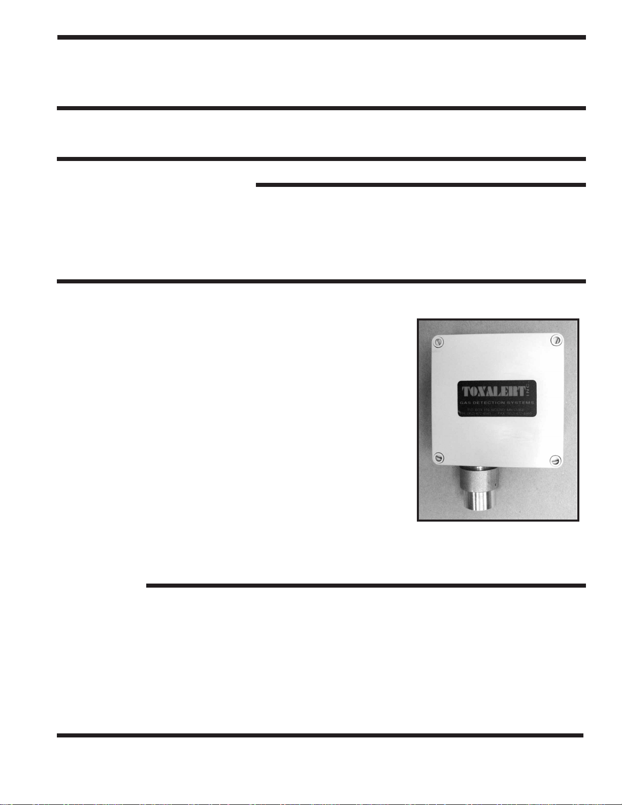
NITROGEN DIOXIDE SENSOR MODEL GVU-NO
DIESEL EXHAUST GAS DETECTOR
TYPICAL INSTALLATIONS:
• Parking Garages • Vehicle Maintenance & Storage
• Bus Garages Highway Departments
• Fire Stations Utilities
• Warehouses Public Works
• Car Dealers • Tunnels
GENERAL DESCRIPTION:
The model GVU-NO2 nitrogen dioxide sensor is designed to interface
with Toxalert International GVU series control units. The Model GVU-
utilizes an electrochemical sensing element and is designed for
NO
2
ambient monitoring applications. It is intended for use in fixed
monitoring installations, and therefore continuous operation. The
GVU-NO
requires a four-wire connection from a controller that provides a
nominal 24VDC power source, common and return signal input. The
GVU-NO
has an effective range of 0-10 ppm. The sensor module
2
has indicators for power on, fault status and high NO2.
2
2
The Toxalert Nitrogen Dioxide (NO
energy savings. A common producer of NO
Diesel exhaust is a know cancer causing agent as reported in the U.S.
Department of Health and Human Services’ Current Intelligence
bulletin 50 dated August 1988. An electrochemical cell is required to
measure such small amounts of NO
measuring NO
in increments of 0.1 ppm.
2
) Transmitter combines safety and
2
is diesel engine exhaust.
2
. The device’s sensor is capable of
2
Model GVU-NO
2
FEATURES:
• Power on indication
• High NO
• Fault Indicator
• Low voltage class two (2) wiring
• Convenient diagnostics
• Simple maintenance
• Operating range meets OSHA standard
TOXALERT INTERNATIONAL, INC., P.O. BOX 159, MOUND, MINNESOTA 55364 (952) 472-4541 FAX (952) 472-4960
Indication
2
Visit our website at www. toxalert. com
Page 2
SPECIFICATIONS
•
Type: Electro-chemical cell diffusion barrier type
•Range: 0 to 10 ppm nitrogen dioxide in air
•Response Time: 30 seconds to 90% indication
•Typical life: Two years in normal service
•Accuracy: +/–5% of full scale
•Resolution: 0.1 ppm
•Operating Temperature: 4º to 122ºF
(–20ºC to 50ºC)
•Relative Humidity: 15 to 90% RH non-condensing
ELECTRICAL DATA:
• Input voltage: 24 VDC (provided from GVU control Unit)
•Wiring: 4 wire non-isolated
UNIT CONSTRUCTION:
•Mounting: Conduit 1/2” and 3/4” NPT or flexible cable
•Housing: Polystyrene, impact-resistant, non flammable, IP66
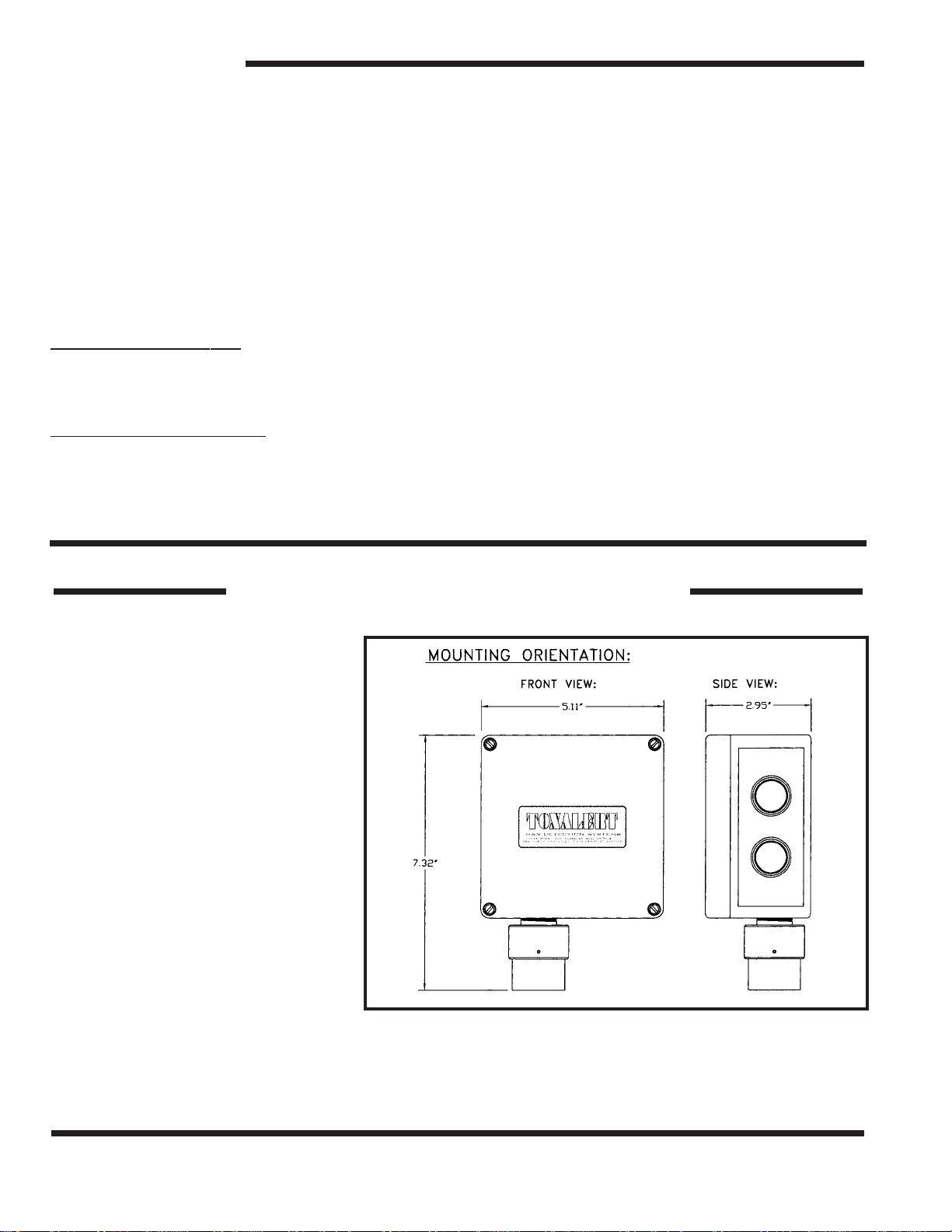
• Physical: 5.11”x 5.11” x 2.95” (13.0 x 13.0 x 7.5 cm)
•Weight: 14.2 oz.
INSTALLATION INSTRUCTIONS
1. INSTALLATION (For specific
details see sensor manual)
Locate a mounting location away
from direct fresh air intakes, and
mount vertically on wall or support
column approximately 3 to 6 feet
above floor. Refer to figures 1 and 2;
Table 1 and 2 and installation instructions in GVU series control unit data
sheet and install the GVU-NO
sensor as follows.
2. MOUNTING SENSOR
Install the module housing onto the
end of the supply conduit and bolt
into position as required.
3. SENSOR WIRING
WARNING: To prevent fire or shock hazard, turn
off power source to control unit before making
connections. Comply with all local building codes and ordinances.
2
Figure 1:
TOXALERT INTERNATIONAL, INC., P.O. BOX 159, MOUND, MINNESOTA 55364 (952) 472-4541 FAX (952) 472-4960
Visit our website at www. toxalert. com
Page 3

INSTALLATION INSTRUCTIONS
NOTE: Refer to Figure 2 and Tables 1 and 2.
Use shielded cable to interconnect sensor and
control unit if metal conduit is not used, or if
conduit also contains AC wiring.
1.) Measure distance between sensing unit
and control unit and select proper wire
or larger wire from Table 1.
2.) Run wiring between control and
sensing unit and into enclosure through
access holes. Connect wires from terminal
blocks in sensing unit to control unit per
Table 2 and GVU series control unit data
sheet.
Figure 2:
4. START-UP
Reference Installation Manual
1.) Verify all wiring connections are correct.
2.) Electronics replacement - Carefully fit the electronics over the two posts in the enclosure and
tighten the captive panel screws.
3.) Apply Power
4.) Green power indicator should light
5.) Replace Cover
6.) Allow 1 hour to warm-up
TABLE 1
AW G DO NOT EXCEED
#22 Wire 500 Ft. Sensor to Controller
#20 Wire 800 Ft. Sensor to Controller
#18 Wire 1300 Ft. Sensor to Controller
#16 Wire 2000 Ft. Sensor to Controller
TOXALERT INTERNATIONAL, INC., P.O. BOX 159, MOUND, MINNESOTA 55364 (952) 472-4541 FAX (952) 472-4960
Visit our website at www. toxalert. com
Page 4

TABLE 2 WIRING CONNECTIONS
GVU-NO
2
CONTROL UNITS
SENSOR GVU-1 GVU-3
J2-1 TB11-24 VDC (+) TB3-H (+24VDC
J2-3 TB11-24 VDC (–) TB3-N (–24VDC)
J3-1 TB2-1 TB1-A1, B1, C1
J3-3 TB2-7 TB1-A7, B7, C7
** TB2-5 TB1-A5, B5, C5
** Shield of cable (if used) should be connected at control unit only. Make sure
sensor end is taped and isolated from terminals or metal
GVU SERIES PRODUCTS:
CONTROLLERS -
GVU-1 Control unit for use with one sensor
GVU-3 Control unit for use with one to three remote sensors
GVU-6 Control unit for use with one to six remote sensors
GVU-12 Control unit for use with one to twelve remote sensors
GVU-18 Control unit for use with one to eighteen remote sensors
REMOTE SENSORS -
GVU-CO Remote carbon monoxide sensor
GVU-CO
GVU-NO
Remote carbon dioxide sensor
2
Remote nitrogen dioxide sensor
2
GVU-VOC Remote smoke/air quality sensor
GVU-NO2 5/07
TOXALERT INTERNATIONAL, INC., P.O. BOX 159, MOUND, MINNESOTA 55364 (952) 472-4541 FAX (952) 472-4960
Visit our website at www. toxalert. com
 Loading...