

Page 1
TM
DATA
TOXALERT
SHEET
CARBON DIOXIDE (CO2) MODEL GVU-CO
DIESEL EXHAUST GAS DETECTOR
TYPICAL INSTALLATIONS:
• Parking Garages • Vehicle Maintenance & Storage
• Bus Garages Highway Departments
• Fire Stations Utilities
• Warehouses Public Works
• Car Dealers • Tunnels
GENERAL DESCRIPTION:
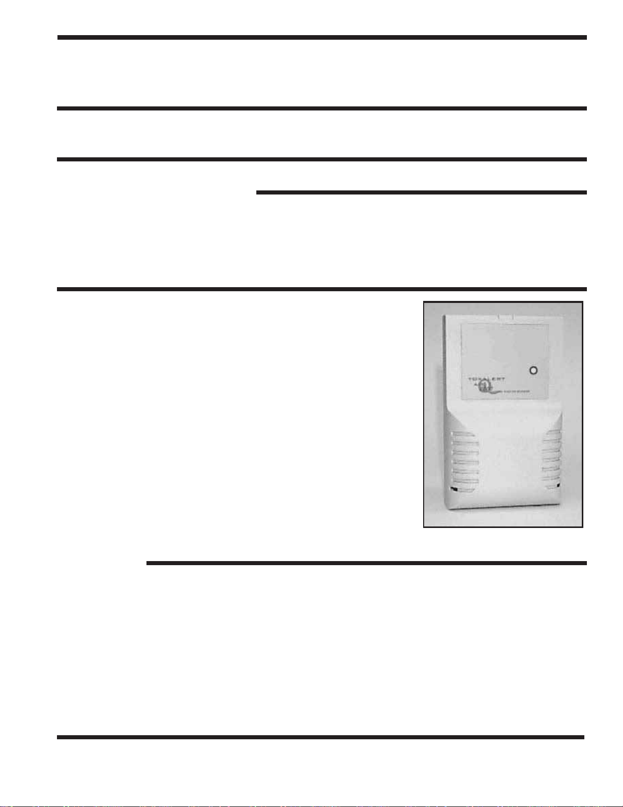
The model GVU-CO2 Carbon dioxide sensor is designed to interface
with a Toxalert Int’l model GVU series control unit. The sensor/transducer consists of a patented solid state infrared CO
an attractive plastic case. The GVU-CO
lithium tantalate detector, updated electronics and unique auto-zero
function. This results in very stable calibration and longer trouble-free
operation in the field. The new IR source is more rugged, operated at
10X derated power and has a life expectancy of 10 years. The new lithium
tantalate detector enhances stability, has less ambient temperature sensitivity and faster response time. The GVU-CO
+
_
2000 ppm with a repeatability of
allow free passage of air to the sensing cell inside.
20 ppm. The enclosure has louvers to
has a new state-of-the-art
2
monitor housed in
2
has a range of 0 to
2
2
Model GVU-CO
FEATURES:
• Microprocessor based
• Power on indication
• 10 year sensing element life
• One calibration gas instead of two
• State-of-the art Infrared Security
• High CO2 indication
• Low voltage class two (2) wiring
• Operating range meets OSHA standard
TOXALERT INTERNATIONAL, INC., P.O. BOX 159, MOUND, MINNESOTA 55364 (952) 472-4541 FAX (952) 472-4960
Visit our website at www. toxalert. com
2
Page 2

BACKGROUND:
The composition of diesel exhaust gases vary with the type of engine and with the rate of operation of
these diesel engines. The prominent noxious gases of diesel engines are NOX [which is made up of NO
(nitric oxide) and NO
(sulfates).
SO
4
Carbon monoxide (CO) sensors do a good job of detecting gasoline engine exhaust fumes, but because
diesel engines output a smaller amount of carbon monoxide, (less than 1%) CO detection is not recommended for sensing diesel exhaust. There are no stable, inexpensive, or easy to maintain sensors for
sensing nitric oxide or nitrogen dioxide which are the poisonous and the dominant diesel exhaust emissions. An investigation R18884*, done by the U.S. Department of Interior, Bureau of Mines shows that
the carbon dioxide (CO
exhaust.
(nitrogen dioxide)], followed by CO (carbon monoxide), SO2 (sulfer dioxide) and
2
) in diesel exhaust is relative to all the noxious gases contained within the diesel
2
The Bureau report states “CO
of the pollutants,” (13%). It further states “CO
is present in the diesel exhaust gases in the highest concentration of any
2
is the only stable and nonreactive pollutant in the ex-
2
haust that is unaffected, to any appreciable extent, by time, emission control devices, or engine wear.” For
these reasons CO
is chosen to be the surrogate gas to be sensed to indicate dangerous levels of the
2
noxious gases contained in diesel exhaust.
The report “established an estimate level of CO
are considered below harmful levels.” The 0.133 percent would be equivalent to 1330 ppm of CO
fore if the CO
in environments where diesel exhaust is present is kept at or below 1300 ppm, a safe
2
–0.133 pct (percent) at which the other diesel pollutants
2
. There-
2
environment will be maintained.
* Report of Investigation 8884:
Diesels in Underground Mining, A review and an Evaluation of an Air
Quality Monitoring Methodology by J. Harrison Daniel, Jr., Staff Engineer, Division of Health & Safety,
Bureau of Mines, Washington, D.C.
SPECIFICATIONS
•
Operating principle: Non Dispersive Infrared
• Gas sampling method: Diffusion
• Range: 0 to 2000 ppm
• Response time: Less than 1 minute
• Operating temperature range: 32ºF to 122ºF
(0ºC to 50ºC)
• Operating humidity: 0-90% RH (non condensing)
• Dimension: 5.2” x 3.2” x 1.4”
• Weight: .5 lbs. (.35 kg)
• Accuracy: + 5% of reading or + 75 ppm, which ever is
greater
• Repeatability: + 20 ppm
• Typical Drift (per year): + 75 ppm ( @1200 ppm)
• Storage temperature: -22ºF to 140ºF
• Input power: 20-30 VAC (provided from GVU
Control unit)
• Power Consumption: Less than 2W @24VAC
__
_
_
(-30ºC to 60ºC)
TOXALERT INTERNATIONAL, INC., P.O. BOX 159, MOUND, MINNESOTA 55364 (952) 472-4541 FAX (952) 472-4960
Visit our website at www. toxalert. com
Page 3

INSTALLATION INSTRUCTIONS
1. INSTALLATION (For specific details see sensor manual)
Locate a mounting location away from direct fresh air intakes,
and mount vertically on wall or support column approximately 3 to 6 feet above floor. Refer to figures 1 and 2; Table 1
and 2 and installation instructions in GVU series control unit
data sheet and install the GVU-CO
2. COVER REMOVAL
sensor as follows.
2
Figure 1:
Model GVU-CO2 Mounting Dimensions
To open the Model GVU-CO
, use a coin in the slot on the
2
bottom to release the snap. Lift the cover up slightly to disengage the closure and remove cover with a downward motion
to clear the catch at the top of the unit.
The locations of controls and terminals on the main circuit
board are shown in Figure 2.
3. MOUNTING
The Model GVU-CO
is designed for flush mounting with two
2
fasteners. The locations of the mounting points
(shown in Figure 1) allow direct mounting on a standard
simplex (single circuit) junction box. There is a wiring cutout in the center of the unit near the terminal
strips.
4. SENSOR WIRING
Model GVU-CO
Figure 2:
Component Locations
2
WARNING: To prevent fire or shock
hazard, turn off power source to control
unit before making connections. Comply
with all local building codes and ordinances.
NOTE: Refer to Figure 2 and Tables 1
and 2. Use shield cable to interconnect
sensor and control unit if metal conduit
is not used, or if conduit also contains
AC wiring.
1.) Measure distance between sensing
unit and control unit and select
proper wire or larger wire from
Table 1.
2.) Run wiring between control and
sensing unit and into enclosure
through access holes. Connect wires
from terminal blocks in sensing unit to control unit per Table 2 and GVU series control unit data
sheet.
TOXALERT INTERNATIONAL, INC., P.O. BOX 159, MOUND, MINNESOTA 55364 (952) 472-4541 FAX (952) 472-4960
Visit our website at www. toxalert. com
Page 4

TABLE 1
AW G DO NOT EXCEED
#22 Wire 500 Ft. Sensor to Controller
#20 Wire 800 Ft. Sensor to Controller
#18 Wire 1300 Ft. Sensor to Controller
#16 Wire 2000 Ft. Sensor to Controller
TABLE 2 WIRING CONNECTIONS
GVU-CO2 GVU-1 GVU-3 Expansion
Sensor Board
Power In (+) TB11-24 VAC TB3-H (24VAC)
Power In (–) TB11-24 VAC TB3-N (24VAC)
Relay Contact TB2-1 TB1-A1, B1, C1
Relay Contact TB2-7 TB1-A7, B7, C7
** TB2-5 TB1-A5, B5, C5
** Shield of cable (if used) should be connected at control unit only. Make sure sensor end is taped and
isolated from terminals or metal
5. START-UP
Reference Installation Manual
1.) Verify all wiring connections are correct.
2.) Cover Replacement - Engage the top center of the cover under the latch at the top of the base, then
press the bottom of the cover onto the bottom of the case until it latches.
3.) Apply Power
4.) Green power LED should light
5.) Allow 5 minutes for warm-up
GVU SERIES PRODUCTS:
CONTROLLERS -
GVU-1 Control unit for use with one sensor
GVU-3 Control unit for use with one to three remote sensors
REMOTE SENSORS -
GVU-CO Remote carbon monoxide sensor
GVU-CO
GVU-NO
GVU-VOC Remote smoke/air quality sensor
Remote carbon dioxide sensor
2
Remote nitrogen dioxide sensor
2
TOX-CO2/ANA 5/05
TOXALERT INTERNATIONAL, INC., P.O. BOX 159, MOUND, MINNESOTA 55364 (952) 472-4541 FAX (952) 472-4960
Visit our website at www. toxalert. com
 Loading...