

Page 1
TM
TOXALERT
DATA
SHEET
CO, CO2, NO2, AND/OR VOC MONITOR
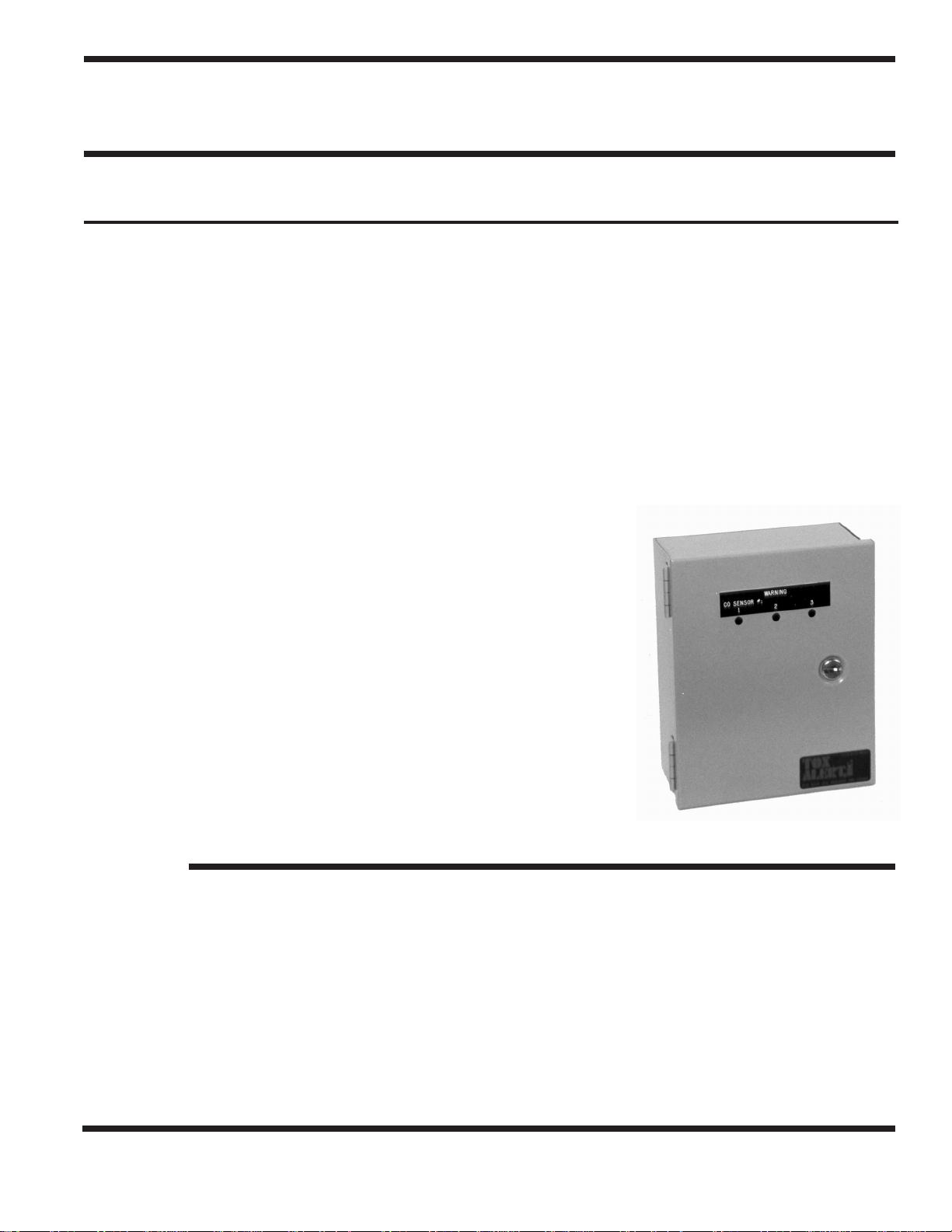
MODEL GVU-3
VEHICLE EXHAUST GAS DETECTOR
GENERAL DESCRIPTION:
The GVU-3 ventilation control system combines toxic gas-based and time-based fan control modes in an all solid-state, low
maintenance, cost effective product.
The GVU-3 series controller can monitor up to three (3) GVU-CO sensors; (3) GVU-CO2 sensors, (3) GVU-NO2 sensors, (3)
GVU-VOC sensors; or any combination of sensors. The GVU-3 Controller consists of the power supply, solid state clocks, time
delays, output relays, terminal strips, 3 sensor alarm LED’s and a green LED to indicate power to remote sensors.
The GVU-CO sensor is microprocessor based and is temperature and humidity compensated for stability. The GVU-CO sensor
range is 0 to 250 ppm. The transducer utilizes a tinoxide sensing element that is cleaned and sampled by the microprocessor. The
GVU-CO indicates its status via a two color LED (light emitting diode). When the LED is flashing green, operation is normal
and not in alarm. When the LED is flashing red, the unit is in alarm (high CO); a continuous red or green indicates sensor
failure; and LED extinguished indicates power failure.
See separate specification data sheet for information regarding GVU-CO2 carbon dioxide sensors, GVU-NO2 nitrogen dioxide
sensor and GVU-VOC smoke/air quality sensor.
TIME CONTROL:
The systems “hour” clock outputs to it’s “fan-on” relay once per hour causing it to
energize. The “on” time of the “fan-on” relay is user adjustable, in one minute
settings from 1 to 8 minutes. The “hour” clock operates in this manner irrespective
of gas concentration, and may be disabled, if desired. To disable “hour” clock
operation, place switch S3 to RST (RESET) position.
DETECTION CONTROL:
Should a high gas concentration occur (above user-adjustable alarm level), an alarm
signal from any sensor unit starts a 30 second delay. Should the concentration persist
through the delay period, the “alarm” clock is activated. The “on” time of this clock,
is user-adjustable in discrete settings from 1 to 8 minutes and its setting is independent of the “hour clock” setting. Upon activation of the “alarm” clock, the “fan-on”
relay energizes and remains energized until the “alarm clock” times out. Should the
high concentration still be above the alarm level, the “fan-on” relay will remain ON
and the “warning” relay will energize. This condition is maintained until the high
concentration drops.
In the event of a power failure, the control unit sets itself to an alarm condition upon
power restoration. Thus, fan activation is assured, to clear possible accumulated
toxic gases.
CONTROL PANEL
FEATURES
• Fully electronic for long life
• User adjustable alarm setting
• User adjustable minimum fan run time
• User adjustable 2nd stage activation
• One person field calibration
• UL listed components
• Key locking sensor
OPTIONS
• Audible alarm with silence switch
• Power ON, Fan ON LED’s on face of controller
TOXALERT INTERNATIONAL, INC., P.O. BOX 159, MOUND, MINNESOTA 55364 (952) 472-4541 FAX (952) 472-4960
Visit our website at www. toxalert. com
• Red LED to indicate high gas concentration for each sensor
• Visual indication of high gas concentration level and fan on
• Automatic fan start-up upon power restoration following power outage
• Operating range meets OSHA std. 1910.1000
• User adjustable clock-activation of fans, if desired
• NEMA 1 std., others available
• Sensor alarm LED’s on face of controller
• Controller key lock
Page 2
SPECIFICATIONS
Input Power: 120 VAC, 60 Hz, 1A (fused)
Relay Contacts: 24 VAC, 2A resistive, 1.5 inductive
Discrete Clock Settings: 1 minute intervals
Automatic Ventilation Cycle Upon
Power Restoration: User adjustable 1 to 8 minutes
Finish: Control Unit: Gray enamel
Enclosure: Nema 1 standard, others available
Dimensions: 14” H x 12” W x 4” D.
(305mm x 102 mm)
Weight: 8 lbs. (3.6 kg)
INSTALLATION INSTRUCTIONS
1. INTRODUCTION
Your TOXALERT Ventilation Control System incorporates the
latest in solid state technology to give you maximum reliability
and perfomance. The system alarm set point can be adjusted to
activate fans upon detection of an unsafe concentration of CO,
CO
, NO2,VOC air quality. In addition, a user-definable hourly
2
repeat cycle is provided, allowing time-based, as well as gasbased fan activation. In both modes of fan control, the “on”
time is user-adjustable 1 to 8 minutes in one minute increments.
For optimum performance, install, burn-in, calibrate and check
out your TOXALERT exactly as instructed. If your
TOXALERT can’t be calibrated or fails checkout, please
contact your local representative or TOXALERT
International for servicing.
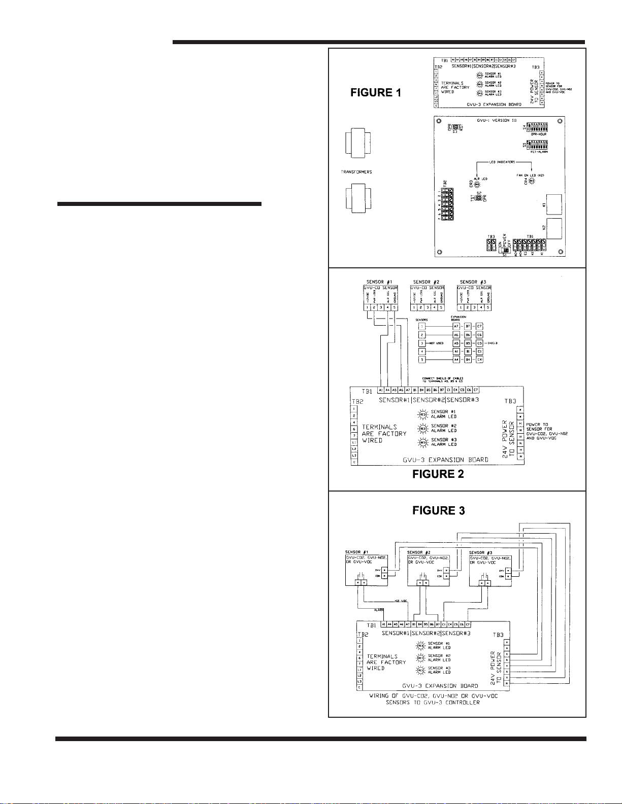
2. INSTALLATION
Refer to figures 1, 2 and 3, and install and connect the
TOXALERT sensors and control units as follows:
GVU-CO SENSING UNITS
1) Open the door using the key provided. Next lift off the front
door by sliding it up the pins of the hinges. Put it aside.
2) Locate a mounting location away from drafts, away from
direct fresh air intakes, and mount vertically on wall or
support column approximately 5 to 6 feet above floor.
3) Mount base with hinge pins along left side by using
mounting holes (4 are available).
4) A wiring access hole must be added to the base anywhere
around the bottom or right side. Do not place an access hole
on the hinge side of the base, since, if conduit is used, this
may restrict the opening of the door. If conduit is to be used,
use a chassis punch to match the required fitting size.
5) Remove any metal chips and burrs from enclosure.
6) Place the cover onto the hinges of the base.
See separate data sheet for installation instructions of
GVU-CO2, GVU-NO2 and GVU-VOC.
TOXALERT INTERNATIONAL, INC., P.O. BOX 159, MOUND, MINNESOTA 55364 (952) 472-4541 FAX (952) 472-4960
Visit our website at www. toxalert. com
Page 3

CONTROL UNIT
1) Unlock and open enclosure cover.
2) If necessary, cut access holes for wiring in enclosure
sides directly opposite terminal blocks to be wired. First
disconnect fuse leads, remove the four screws that secure
chassis plate to enclosure and then care fully remove plate
and attached transformer and circuit boards; cut holes and
remove metal chips and burrs from enclosure.
3) Mount enclosure with four screws.
4) Reinstall and secure chassis plate to enclosure with the
four screws and reconnect fuse leads removed in step (2).
5) Connect to 120 VAC, 60 Hz power source.
SENSOR WIRING
NOTE: Refer to Figures 2 and 3 and Tables 1 and 2. Use
shielded cable to interconnect sensors and control units if
metal conduit is not used, or if conduit also contains AC
wiring.
1) Measure distance between sensing unit and controller unit
and select proper size wire or larger wire from Table 1.
2) Run wiring between controller and sensing units and into
enclosure through access holes. Connect wires from
terminal blocks in sensing unit to appropriate sensor #
terminal (TB-1 of GVU-3 expansion board) in control unit
per Figure 2 and/or 3.
TABLE 1
AW G DO NOT EXCEED
#20 Wire 800 Ft. Sensor to Controller
#18 Wire 1300 Ft. Sensor to Controller
#16 Wire 2000 Ft. Sensor to Controller
POWER AND RELAY WIRING
WARNING: To prevent fire or shock hazard turn off
control unit and fan power sources before making
connections to control unit. Comply with all local building
codes and ordinances.
1) Connect power to TB1 of GVU-1, version II board as
follows:
AC hot to TB1-1 (ACM)
AC neutral to TB1-2 (ACN)
AC ground to TB1-3 (KG)
CAUTION:
load. If a higher rated alarm or pilot control is required, add a
remote relay between the control relay and load.
Relays K1 and K2 are rated for a 5.0 amps resistive
2) Connect dry contacts of alarm Kl (TB1-6 and TB1-7) to
alarm device (optional).
3) Connect dry contacts of fan relay K2 (TB1-4 and TB1 5)
to fan pilot control.
4) Set control unit power switch S1 to the off position,TST/
OPR switch S2 to OPR and OPR/RST switch S3 to RST.
5) Turn on control unit AC power source, but do not
apply power to fans at this time.
3. BURN-IN
Burn-in period allows sensor to stabilize before proceeding
with alarm setting procedure.
1) Be sure fan power is off, power is applied to control
unit and power switch S1 is set to PWR ON.
2) Allow system with CO/VOC sensors to burn-in at least 72
hours with power turned on to sensors.
Allow CO2 / NO2sensors 1 hour to burn-in.
3) When 72 hour burn-in is complete, proceed with
alarm setting and checkout.
4. SETTING OF TIMING FUNCTIONS:
There are two (2) eight position dip switches in the upper right
hand corner of the GVU-1 controller board, labeled S4 and S5.
These control the system’s timing functions.
A) Hourly Operations (S4)
S4 and Toggle switch S3, in the upper left corner of the P.C.
board control the hourly operation of K-2 relay. With number
“1” switch of S4 in the up position, the fan will run one
minute each hour; with the number “2” switch in the up
position, system will run 2 minutes every hour: and so on, up
to eight (8) minutes. The switches are not additive and if more
than one switch of S4 is in the up position, the system operates
the lowest number of minutes of the S4 switches in the up
position. With S3 in RST (reset) position the hourly function is
deactivated. If S3 is in the OPR position and all S4 switches
are down (off), K2 will operate 8 minutes each hour.
B) Minimum Fan Run Time (S5)
Dip switch S5 controls the minimum time K2 relay is activated
once an alarm condition has been acknowledged by the controller. With number “1” switch of S5 in the up position, the
minimum run time (K2 relay closed) is one minute. With
number “2” switch of S5 in the up position, the minimum run
time is 2 minutes, and so on, up to 8 minutes. The switches are
not additive, and if more than one switch is in the up position,
K2 operates the number of minutes of the “lowest” numbered
switch of S5 in the up position. If all are in the down position,
the minimum run time defaults to 8 minutes.
TABLE 2 (Refers to Figures 2 and 3)
CO SENSOR TERMINALS GVU-3 SENSOR EXPANSION BOARD TERMINALS C02 / N02 SENSOR TERMINALS
Sensor #l Sensor #2 Sensor #3 Function
1A7B7C7 (+ 12 VDC Power) Normally open relay terminal
2A6B6C6 (Sensor Power Loss) NA
4A1B1C1 (Alarm Input) Normally open relay terminal
5A4B4C4(Ground) NA
No Connection* A5 B5 C5 (Cable Shield) No Connection*
NA TB3-Hot (24 VAC Power) VAC (+)
NA TB3-Neutral (24 VAC Power) VAC (–)
TOXALERT INTERNATIONAL, INC., P.O. BOX 159, MOUND, MINNESOTA 55364 (952) 472-4541 FAX (952) 472-4960
Visit our website at www. toxalert. com
Page 4

5. ALARM SETTING PROCEDURES
All sensors are factory calibrated for their specific setpoint.
Periodic calibration is required and performed at the sensor.
Please refer to the individual sensor instruction manual (supplied with each sensor) and calibration instruction sheet
(supplied with calibration kits, available seperately).
6. CHECKOUT
1) Turn off power.
2) Disconnect alarm input wires from sensors at terminals A1,
B1 & C1 of GVU-3 board.
3) Set alarm timer (S5) to 2 minutes and hour timer (S4) to 1
minute.
4) Set power switch S1 to PWR On. Set OPR/RST switch S3
to RST and back to OPR, note time.
5) Check that the LED indicators CR3 and CR4 on GVU1
board are extinguished and that fans are off.
6) Set TST/OPR switch S2 to TST, check that the CR3 LED
indicator is ON. After 30 seconds check that CR4 and the
fans are on. Set S2 to OPR (CR3 off) and check that the
fans stop after running 2 minutes (CR4 off).
7) Set TST/OPR switch S2 to TST, check that when 2 1/2
minutes have elasped (this includes the delay), alarm
device activates and fans continue to run. If optional alarm
is not installed, connect an ohm-meter across TB1-6 and
TB 1-7 and check that contacts of relay K1 are closed
(continuity).
8) Set S2 to OPR. Check that fans stop and K1 de-energizers
(CR3 and CR4 off).
9) Check that 1 hour after step (2) was performed, fans start
(CR4 lights) run for 1 minute.
10) Check power switch S1 to off position, set alarm and hour
timers to desired setting.
11) To disable hour clock operation, position switch S3 to RST
position.
12) Reconnect sensor alarm input wires, to A1, B1 & C1.
13) Set power switch S1 to PWR ON, close and lock enclo sure cover. This completes the checkout and installation.
GVU SERIES PRODUCTS:
CONTROLLERS –
GVU-1 Control unit for use with one sensor
GVU-3 Control unit for use with one to three remote sensors
GVU-6 Control unit for use with one to six remote sensors
GVU-12 Control unit for use with one to twelve remote sensors
GVU-18 Control unit for use with one to eighteen remote sensors
REMOTE SENSORS –
GVU-CO Remote carbon monoxide sensor GVU–NO
Remote nitrogen dioxide sensor
2
GVU-CO2Remote carbon dioxide sensor GVU–VOC Remote smoke/air quality sensor
GVU-3 2/06 TMK
TOXALERT INTERNATIONAL, INC., P.O. BOX 159, MOUND, MINNESOTA 55364 (952) 472-4541 FAX (952) 472-4960
Visit our website at www. toxalert. com
 Loading...