

Page 1
TM
DATA
TOXALERT
CO / CO
/ NO2 / OR VOC MONITOR MODEL GVU-1
2
SHEET
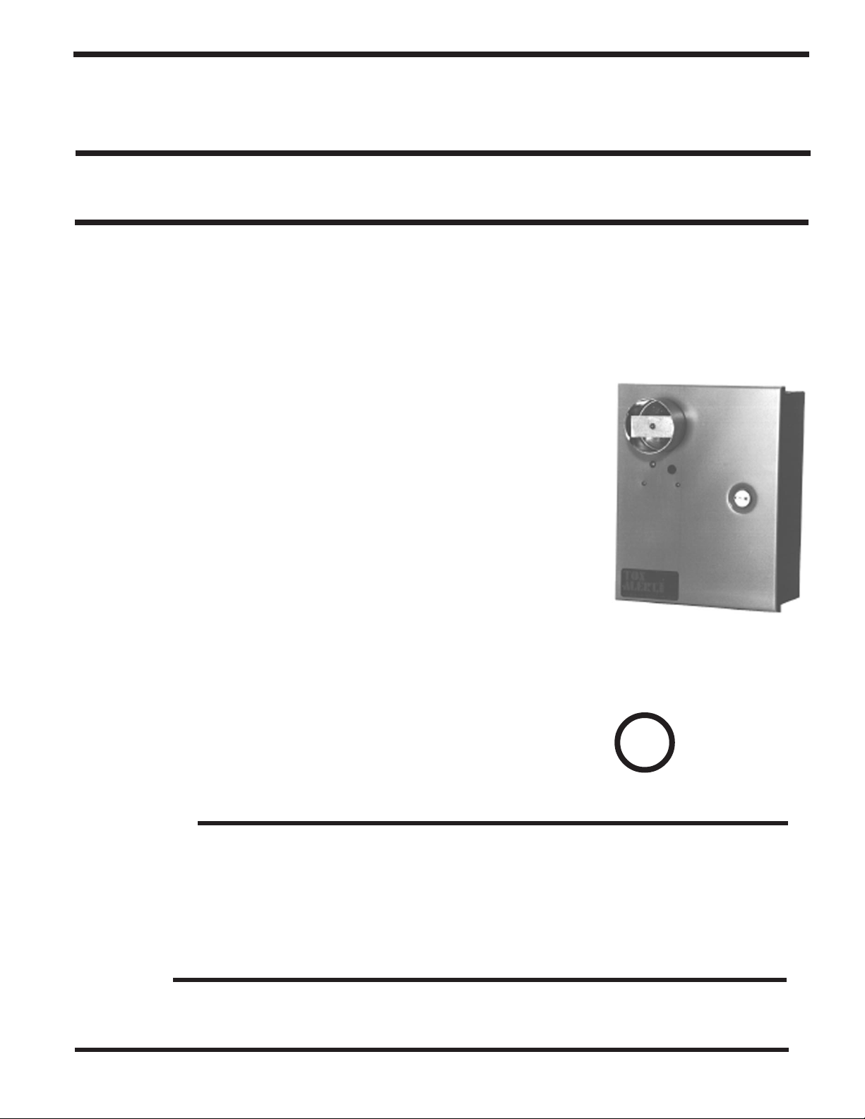
VEHICLE EXHAUST GAS DETECTOR
GENERAL DESCRIPTION:
The GVU-1 ventilation control monitor combines toxic gas sensing and time-based fan control modes in an all solidstate, low maintenance, cost effective product.
The GVU-1 controller consists of the power supplies, solid state clocks, time delays, and output relays. It can continuously monitor one of the following Toxalert sensors: GVU-CO carbon monoxide sensor, GVU-CO
GVU-VOC diesel smoke/air quality sensor. See last page for ordering information. (Please refer to applicable sensor data sheets).
TIME CONTROL:
The systems hourly timeclock outputs to the fan-on relay once per hour causing it
to energize. The on time of the fan-on relay is user adjustable, in one minute
increments from 1 to 8 minutes. The hourly timeclock operates in this manner
irrespective of sensor reading, and may be disabled, if desired. To disable the
hourly clock operation, place switch S3 to RST (RESET) position.
carbon dioxide sensor, GVU-NO2 nitrogen dioxide sensor or
2
VENTILATION CONTROL:
Should a high toxic concentration occur (above user adjustable alarm level), a 30
second delay timer will start. Should the concentration persist through the delay
period, the “alarm” clock is activated. The “on” time of this clock is user adjustable in discrete settings from 1 to 8 minutes and its setting is independent of the
hourly clock setting. Upon activation of the “alarm” clock, the “fan-on” relay
energizes and remains energized until the “alarm clock” times out. Should the
concentration still be above the alarm level, the “fan-on” relay shall remain ON
and the alarm relay shall energize. This condition is maintained until the concentration drops.
In the event of a power failure, the control unit sets itself to an alarm condition
upon power restoration. Thus, fan activation is assured, clearing out any accumulated toxic gases.
FEATURES
• User adjustable alarm setting
• User adjustable minimum fan run time
• User adjustable 2nd stage activation
• Completely solid-state for long life
• Controller LED indicators for high
concentration signal and fan on
• Operating range meets OSHA std. 1910.1000.
• UL listed upon request.
• Automatic fan start-up upon power r estoration
following power outage if desired.
• User adjustable clock activation of fans, if desired.
• NEMA 1 enclosure standard- others available.
OPTIONS
GVU-1A
(Control unit w/ integral CO sensor)
U
® L
Underwriters
Laboratories, Inc. ®
LISTED
• Audible alarm with silence switch
• Power on indicator
TOXALERT INTERNATIONAL, INC., P.O. BOX 159, MOUND, MINNESOTA 55364 (952) 472-4541 FAX (952) 472-4960
Visit our website at www. toxalert. com
• Fan on indicator
• High gas concentration indicator
Page 2
SPECIFICATIONS
• Automatic fan run upon power restoration
• Input power: 120VAC, 60 Hz, 1A (fused)
• Relay contacts: 24VAC, 2A resistive, 1.5A inductive
• Timers: 30 second delay on
Min. Fan Run Time 1-8 minutes
Hourly Fan Run: 0-8 minutes
INSTALLATION INSTRUCTIONS
1. INTRODUCTION
Your TOXALERT ventilation control system incorporates the latest in solid state technology to give you
maximum reliability and performance. The system
alarm setpoint can be adjusted to activate fans upon
detection of an unsafe gas concentration such as carbon
monoxide, carbon dioxide, diesel smoke. In addition, a
user definable hourly repeat cycle is provided, allowing
time based, as well as concentration based fan activation. In both modes of fan control, the “on “ time is
user adjustable from 1 to 8 minutes in one minute
increments. For optimum performance, install, burn-in,
and check out your TOXALERT system exactly as
instructed. If your TOXALERT can’t be calibrated or
fails checkout, please contact your local representative
or TOXALERT International for servicing.
• Enclosure:
Nema 1 standard, others available
Dimensions: 12”H x 12”W x 4”D
(305mm x 305mm x 102mm)
Finish: Gray enamel
Weight: 8 lbs. (3.6kg)
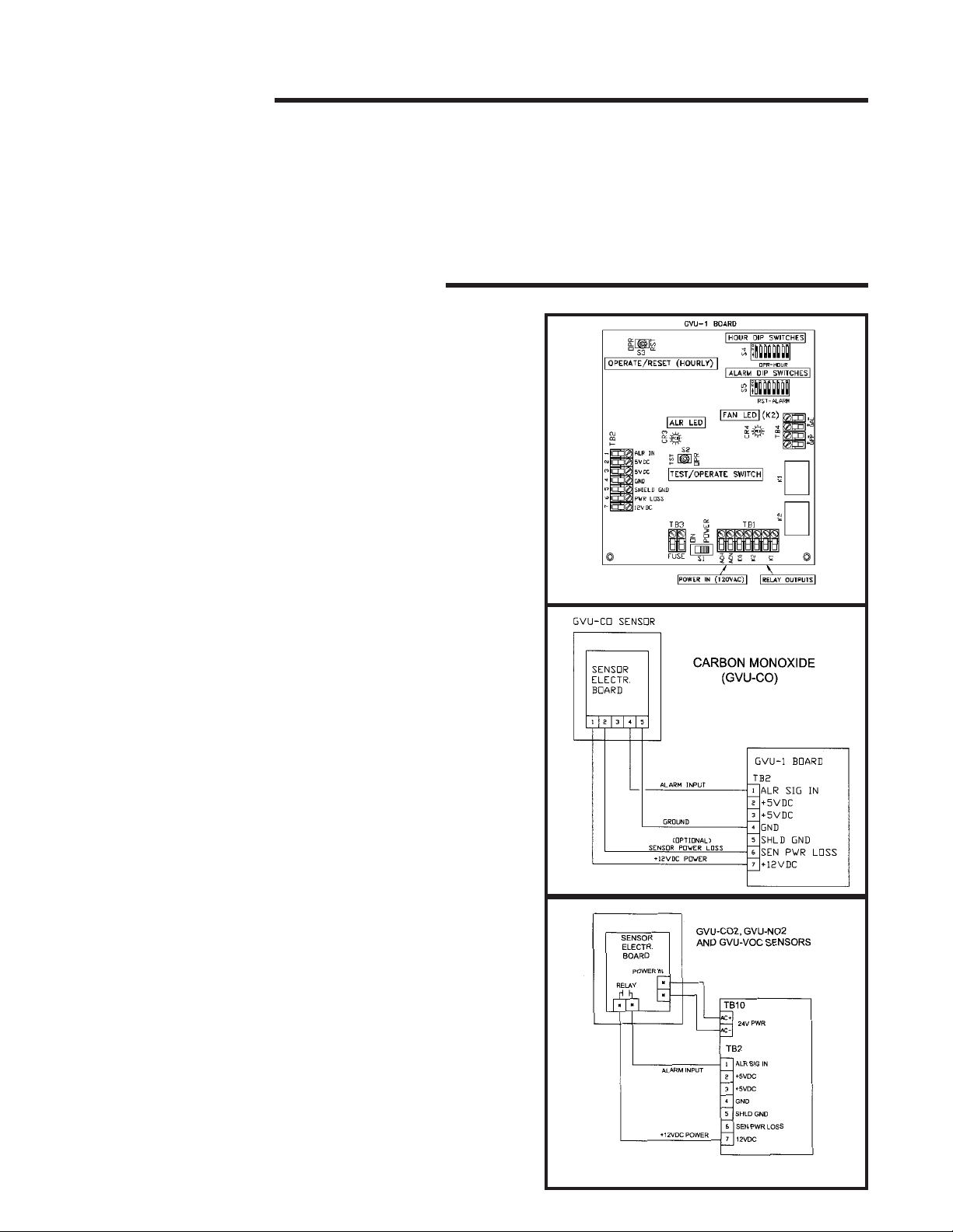
FIG. 1
2. INSTALLATION
Locate a mounting location for the sensor away from
direct fresh air intakes, exhaust and/or supply fans, and
mount vertically on wall or support column normally 5
to 6 feet above floor (NO2 and CO2 sensor height may
differ per application). Mount GVU-VOC sensor in
ceiling. Refer to figs. 1, 2 and 3, to install and connect
the TOXALERT control unit and sensors as following.
(Please refer to job specific documentation for more
detailed wiring options).
CONTROL UNIT-
1) Unlock and open enclosure cover.
2) If necessary, cut access holes for wiring in enclosure
sides directly opposite terminal block TB2 and
slightly below terminal block TB1. First, remove the
four screws that secure chassis plate to enclosure
and then carefully remove plate and attached circuit
board; cut holes and remove metal chips from enclosure.
3) Mount enclosure with four screws.
4) Reinstall and secure chassis plate to enclosure with
the four screws
FIG. 2
SENSORS- Please refer to applicable sensor data sheets
for mounting directions.
FIG. 3
Page 3

SENSOR WIRING
NOTE: Refer to figs. 2 and 3 and tables 1 and 2. Use
shielded cable to interconnect sensing and control
unit if metal conduit is not used, or if conduit also
contains AC wiring.
NOTE: Comply with all local building codes and
ordinances.
1) Measure distance between sensing unit and control
unit and select proper size wire or larger wire from
Table 1.
2) Run wiring between control and sensing unit and
into enclosure through access holes. Connect
wires from terminal blocks in sensing unit to TB2
in control unit per figs. 2 & 3.
TABLE 1
AWGDO NOT EXCEED
#22 Wire 500 Ft. Sensor to Controller
#20 Wire 800 Ft. Sensor to Controller
#18 Wire 1300 Ft. Sensor to Controller
#16 Wire 2000 Ft. Sensor to Controller
TABLE 2
CONTROL UNIT TERMINALS
TB1-ACH (AC Power in- 120 VAC HOT)
TB1-ACN (AC Power in- 120VAC NEU)
TB1-EG (Ground)
TB1-K2(2) (Fan pilot relay contacts)
TB1-K1(2) (Alarm relay contacts)
TB2-1 (Alarm input)
TB2-2 (Sensor power loss)
TB2-3 (+5VDC)
TB2-4 (+5VDC)
TB2-5 (Cable shield*)
TB2-6 (Power loss)
TB2-7 (+12VDC)
TB10 (24VAC or 24VDC+)
TB10 (24VAC or 24VDC-)
Terminal strip TB-2 (figs. 2 & 3) is the control I/O
between the GVU-1 control unit and the sensing unit.
(NOTE: This terminal strip will supply 12VDC
power to the GVU-CO SENSOR ONLY via terminal 7. Power for any other sensor type will be
supplied at terminal strip TB-10).
*Shielding of cable should be connected at only one
end when grounded metallic conduit is not used, or
shared with AC wiring. Connect shielding at terminal
5, TB-2 of control unit. Make sure shielding at sensor
end is taped and isolated from any terminal or metal.
CONTROL UNIT WIRING
WARNING: To prevent fire or shock hazard turn off
control unit and fan power sources before making
connections to control unit. Comply with all local
building codes and ordinances.
1) Connect power to TB-1 as follows:
AC hot to TB1-1 (ACH)
AC neutral to TB1-2 (ACN)
AC ground to TB1-3 (EG)
CAUTION: Relays K1 and K2 are rated for 2.0 amps
resistive load. If a higher rated alarm or pilot control
is required, add a remote relay between the control
relay and load.
2) Connect dry contacts of alarm K1 (TB1-6 and
TB1-7) to alarm device (optional).
3) Connect dry contacts of fan relay K2 (TB1-4 and
TB1-5) to fan pilot control.
4) Set unit power switch S1 to the off position, TST/
OPR switch S2 to OPR and OPR/RST switch to
RST.
5) Turn on control unit AC power source, but do not
apply power to fans at this time.
3. BURN-IN (GVU-CO & GVU-VOC SENSORS
ONLY)
Burn-in allows sensor to stabilize before proceeding
with alarm setting procedure.
1) Be sure fan power is off, power is applied to
control unit and power switch S1 is set to
PWRON.
2) Allow system to burn-in for a minimum of 72
hours with power turned on to sensor.
3) When 72 hours have elapsed, proceed with system
check-out.
4. SETTING OF TIMING FUNCTIONS
There are two (2) eight position DIP switches in the
upper right hand corner of the GVU-1 control board,
labeled S4 and S5. These control the systems timing
functions.
Hourly Operations (S4)
S4 and toggle switch S3, in the upper left corner of
the GVU-1 board control the hourly operation of the
K-2 relay. With the number “1” switch of S4 in the
up position, the fan will run one minute each hour;
with the number “2” switch in the up position, the
system will run two minutes every hour; and so on,
up to eight minutes. The switches are not additive
and if more than one switch on S4 is in the up position, the system operates the lowest number of
minutes of the S4 switches in the up position. With
S3 in RST (reset) position, the hourly function is
Page 4

deactivated. If S3 is in the OPR position and all S4
switches are down (off), K2 will operate 8 minutes
each hour.
B) Minimum Fan Run Time (S5- Alarm setting)
Dip switch S5 controls the minimum time the K2
relay is activated once an alarm condition has been
acknowledged by the controller. With number “1”
switch of S5 in the up position, the minimum fan run
time (K2 relay closed) is one minute. With number
“2” switch of S5 in the up position, the minimum run
time is 2 minutes, and so on, up to 8 minutes. The
switches are not additive, and if more than one switch
is in the up position, K2 operates the number of
minutes of the lowest numbered switch of S5 in the
up position. If all are in the down position, minimum
run time defaults to 8 minutes.
5. ALARM SETTING PROCEDURES
All sensors are factory calibrated for their specific
setpoints. Periodic calibration is required and performed at the sensor. Please refer to the individual
sensor instruction manual (supplied with each sensor)
and calibration instruction sheet (supplied with
calibration kits, available separately). Annual sensor
calibration check is recommended as a minimum.
6. CHECKOUT
Refer to figure 1 and table 2 to check out installation
as follows:
1).Turn power off
2).Disconnect alarm input wires from sensors at
TB2-1.
3).Set alarm timer (S5) to 2 minutes and hourly
timer (S4) to 1 minute, and S2 to OPR.
4).Set power switch S1 to PWR ON. Set OPR/RST
switch S3 to RST and back to OPR; note time.
5).Check that the LED indicators CR3 and CR4 and
the fans are off.
6).Set TST/OPR switch S2 to TST, checkout that the
CR3 LED indicator is ON. After 30 sec. check
that CR4 LED and the fan(s) are on. Set S2 to
OPR (CR3 off) and check that the fans stop
running after 2 minutes. (CR4 off).
7).Set TST/OPR switch to TST, check that when
2 1/2 minutes have elapsed (this includes the
delay) alarm device activates and fans continue to
run. If optional alarm is not installed, connect an
ohm meter across TB1-K1 and check that
contacts of relay K1 are closed (continuity).
8).Set S2 to OPR. Check that fans stop and K1
deenergizes (CR3 and CR4 are off).
9).Check that 1 hour after step (4) was performed,
fans start (CR4 lights) and run for 1 minute.
10).Set power switch S1 to off position, set alarm
and hour timers to desired settings.
11).T o disable hour clock operation, move switch S3
to RST position.
12).Reconnect sensor alarm input wire removed in
step (2).
13).Set power switch S1 to PWR ON, Close and
lock enclosure cover. This completes checkout
and installation.
ORDERING INFORMATION
CONTROLLERS-
GVU-1/CO Control unit for use with remote
carbon monoxide sensor (GVU-CO)
GVU-1/CO
REMOTE SENSORS (Order separately)GVU-CO Remote carbon monoxide sensor
GVU-CO
GVU-1A Control unit with integral CO sensor
GVU-1B Control unit with integral CO2 sensor
2
Control unit for use with remote
2
carbon dioxide sensor (GVU-CO2)
Remote carbon dioxide sensor
Options, such as additional relays, indicators, local or remote horns, etc. can be ordered along with control unit.)
GVU-1 Revised 5/05
TOXALERT INTERNATIONAL, INC., P.O. BOX 159, MOUND, MINNESOTA 55364 (952) 472-4541 FAX (952) 472-4960
Visit our website at www. toxalert. com
GVU-1/NO
GVU-1/VOC Control unit for use with remote
GVU-VOC Remote smoke/air quality sensor
GVU-NO
GVU-1C Control unit with integral VOC sensor
GVU-1D Control unit with integral NO2 sensor
2
Control unit for use with remote
2
nitrogen dioxide sensor (GVU-NO2)
smoke/air quality sensor (GVU-VOC)
Remote nitrogen dioxide sensor
 Loading...